


Factory Packaged Controls
MHGRV-X Controller
Field Technical Guide

TABLE OF CONTENTS |
|
|
CONTROLLER OVERVIEW............................................................................................................... |
|
3 |
Features................................................................................................................................................................... |
|
3 |
INSTALLATION & WIRING............................................................................................................... |
|
4 |
Important Wiring Considerations.............................................................................................................................. |
|
4 |
MHGRV-X Controller to AAON Unit Controller Wiring.............................................................................................. |
|
5 |
MHGRV-X Stand Alone Wiring................................................................................................................................. |
|
6 |
INPUTS AND OUTPUTS .................................................................................................................. |
|
7 |
OPERATION OVERVIEW .................................................................................................................. |
|
8 |
Initialization .............................................................................................................................................................. |
|
8 |
Modulating Hot Gas Valves...................................................................................................................................... |
|
8 |
Modes of Operation ................................................................................................................................................. |
|
8 |
Additional Features .................................................................................................................................................. |
|
8 |
LCD DISPLAY SCREENS.................................................................................................................. |
|
9 |
TROUBLESHOOTING..................................................................................................................... |
|
13 |
Using LEDs to Verify Operation ............................................................................................................................. |
|
13 |
Temperature Sensor Testing ........................................................................................................................................ |
|
14 |
APPENDIX A - Supply Air Temperature Sensor Guide |
................................................................. |
17 |
Supply Air Temperature Sensor Installation ........................................................................................................... |
|
17 |
Supply Air Temperature Sensor Wiring Chart and Jumper Settings ...................................................................... |
18 |
|
APPENDIX B .................................................................................................................................. |
|
19 |
MHGRV-X Replacement of MHGRV II................................................................................................................... |
|
19 |
APPENDIX C .................................................................................................................................. |
|
20 |
Reheat Expansion Module..................................................................................................................................... |
|
20 |
PART NUMBER CROSS REFERENCE TABLE |
|
|
PART DESCRIPTION |
|
AAON |
|
ORION |
|
|
|
TULSA |
MHGRV-X Controller |
OE377-26-00059 |
V12100 |
Reheat Expansion Module |
OE377-01-00059 |
V42450 |
MODGAS-X Controller |
OE377-26-00058 |
V12090 |
Supply Air Temperature Sensor |
OE231 |
P87140 |
EBC E-BUS Cables - Varying Lengths |
EBC-XXX-F |
N/A |
|
|
www.aaon.com |
|
|
|
|
|
|
WattMaster Controls Inc. |
WattMaster Form: AA-MHGRVX-FIELD-TGD-01H |
|
|
8500 NW River Park Drive · Parkville, MO 64152 |
Copyright April 2015 WattMaster Controls, Inc. |
|
|
Toll Free Phone: 866-918-1100 |
AAON® Manual Part No.: V16950 |
|
|
PH: (816) 505-1100 · FAX: (816) 505-1101 |
AAON® is a registered trademark of AAON, Inc., Tulsa, OK. |
|
|
E-mail: mail@wattmaster.com |
Neither WattMaster Controls, Inc. nor AAON® assumes any |
|
|
Visit our web site at www.orioncontrols.com |
responsibility for errors or omissions in this document. |
|
|
|
This document is subject to change without notice. |
|
|
|
|
|
|
|
|
|
2 |
MHGRV-X Field Technical Guide |

OVERVIEW
MHGRV-X Controller General Information
Overview |
Features |
|
|
|
|
The OE377-26-00059 MHGRV-X Controller (AAON Part No. V12100) is designed to control a Modulating Hot Gas Reheat Valve to maintain a desired Supply Air Temperature setpoint. The controller can be used as a stand-alone controller or can be used in conjunction with any AAON unit controller.
In addition, up to (7) Reheat Expansion Modules can be connected to the Controller and to each other for additional Reheat Valve Control.
The MHGRV-X controller connects to an AAON unit controller or expansion module via a modular cable. Depending on the type of unit controller, this connection will utilize an I2C connection or an E-BUS connection.
When using the MHGRV-X Controller to replace an existing MHGRV II Controller, see Appendix B, page 19 for details.
See Figure 1 for dimensions (in inches).
The MHGRV-X provides the following:
Can be operated as a stand-alone controller or communicating with AAON unit controllers.
Provides for Supply Air Temperature Setpoint reset when required
Second stage reheat capability when using 2 Hot Gas Reheat Valves
Control of reheat solenoid valve to provide coil flushing for positive refrigerant oil return
Can provide further Reheat control using up to (7) Reheat Expansion Modules
Contains a 2 x 8 LCD character display and 4 buttons that allow for status display, setpoint changes, and configuration changes
5.73 |
|
5.24 |
|
2.62 |
|
5.04 |
5.63 |
0.21 |
|
2.04 |
|
0.57 |
Note: Depth is 1.49 inches. |
|
|
4.09 |
|
Figure 1: OE377-26-00059 MHGRV-X Controller Dimensions |
|
MHGRV-X Field Technical Guide |
3 |

WIRING
Installation & Wiring
Installation & Mounting
The MHGRV-X Controller is housed in a plastic enclosure. It is designed to be mounted by using the 3 mounting holes in the enclosure base. It is important to mount the module in a location that is free from extreme high or low temperatures, moisture, dust, and dirt. Be careful not to damage the electronic components when mounting the module.
NOTE: The MHGRV-X Controller contains no user-serviceable parts. Contact qualified technical personnel if your Controller or Module is not operating correctly.
General Wiring Information
Depending on if the MHGRV-X Controller is to be connected to the HVAC controller or is to be used as a stand-alone controller determines how the MHGRV-X should be wired. For the wiring diagram to use when the MHGRV-X Controller is connected to an AAON Unit Controller, see Figure 2, page 5. For the stand-alone wiring diagram, see Figure 3, page 6.
For Reheat Expansion Module wiring, see Figure 9, page 22.
Please carefully read and apply the following information when wiring the MHGRV-X controller and its expansion board(s):
1.18 gauge minimum wire unless otherwise noted.
2.24 VAC power connection with an appropriate VA rating.
3.Supply Air Temperature Sensor and Heat Enable must have 24 gauge minimum wire.
4.All 24 VAC wiring must be connected so that all ground wires remain common. Failure to follow this procedure can result in damage to the module and connected devices.
5.All wiring is to be in accordance with local and national electrical codes and specifications.
6.Check all wiring leads at the terminal block for tightness. Be sure that wire strands do not stick out and touch adjacent terminals. Confirm that all transducers required for your system are mounted in the appropriate location and wired into the correct terminals.
4 |
MHGRV-X Field Technical Guide |
WIRING
MHGRV-X to AAON Unit Controller Wiring
Communications Wiring
For connection to a VCB-X Controller, VCB-X Expansion Module, and Reheat Expansion Module, use an E-BUS Cable to connect to the appropriate E-BUS port on those modules and/or controller.
For all other controllers, including the VAV/CAV, MUA,VCM, VCM-X, SA, and RNE Controllers, use an I2C Cable connecting to the appropriate I2C ports on those controllers.
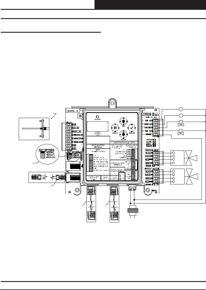
When connected to an AAON Unit Controller, the Supply Air Temperature Sensor is attached to the Main Controller. See Figure 2 below.
See the SAT Wiring Conditions Table and SAT OPTIONS jumper settings in Tables 7 & 9, page 18.
|
MHGRV-X CONTROLLER |
|
|
(OE377-26-00059) |
|
Connect Supply Air Temperature |
|
|
Sensor To AI2 & GND |
|
Fan |
On Main Controller |
|
C1 |
(This Does Not Apply To |
|
|
|
Compressor |
|
CAV/VAV Or MUA Applications) |
|
|
|
C2 |
|
|
|
|
|
|
HGR Solenoid Valve |
Supply |
|
|
Air Temperature |
|
|
Sensor |
|
|
|
|
2 Position HGR Valve (Optional) |
Mount In Supply |
|
COMM |
Air Duct |
|
|
|
|
|
See Table 9 On Page 18 |
|
Condenser Valve #1 |
|
|
|
For SAT OPTIONS |
|
BLK |
Jumper Settings. |
|
|
|
WHT |
|
Only One Supply Air |
|
|
|
RED |
|
Temperature Sensor Can Be |
|
|
Used Per Application. |
|
GRN |
|
|
BLK |
|
|
WHT |
|
|
GRN |
|
|
RED |
I2C Cable |
|
HGR Valve #1 |
Connects To |
|
|
I2C Port On |
|
24VAC |
Any Non VCB-X Controller Or |
GND |
|
Expansion Module |
||
EBC E-BUS Cable |
EBC |
|
|
E-BUS |
40 VA |
||
Connects To |
|||
Cable |
Transformer |
||
VCB-X Expansion |
|||
Connects |
Minimum |
||
Port When Used |
|||
To Reheat |
|
||
With VCB-X |
|
||
Expansion |
|
||
Controller |
Line |
||
Module |
|||
|
|
Figure 2: MHGRV-X Controller to AAON Unit Controller Wiring
MHGRV-X Field Technical Guide |
5 |

WIRING
MHGRV-X Stand-Alone Wiring
Stand-Alone Wiring
In Stand-Alone mode, the MHGRV-X connects to the E-BUS port of the Reheat Expansion Module with an EBC E-BUS cable.
See the SAT Wiring Conditions Table and SAT OPTIONS jumper settings in Tables 7 & 8, page 18.
See Figure 3 below.
|
|
MHGRV-X CONTROLLER |
|
|
|
(OE377-26-00059) |
|
0-10VDC |
|
|
Fan |
- |
|
|
|
External Reset |
|
C1 |
|
|
|
||
Signal |
+ |
|
Compressor |
|
|
|
C2 |
H1 (Dehumidification) |
|
HGR Solenoid Valve |
|
|
|
|
|
Heating Override |
|
|
|
|
|
|
2 Position HGR Valve (Optional) |
Cooling Override |
|
|
COMM |
|
|
|
|
Mount In Supply |
|
|
|
Air Duct |
|
|
|
|
|
|
Condenser Valve #1 |
Supply |
|
|
BLK |
Air Temperature |
|
|
|
Sensor |
|
|
WHT |
|
|
|
RED |
|
|
|
GRN |
|
|
|
BLK |
|
|
|
WHT |
|
|
|
GRN |
|
|
|
RED |
See Table 8 On Page 18 |
|
HGR Valve #1 |
|
For SAT OPTIONS Jumper Settings. |
|
||
|
|
||
Only One Supply Air Temperature |
GND |
24VAC |
|
Sensor Can Be Used Per Application. |
|||
|
|
||
EBC E-BUS |
|
|
Cable Connects |
40 VA |
|
To Reheat |
||
Transformer |
||
Expansion |
||
Minimum |
||
Module |
||
|
||
|
Line |
Figure 3: MHGRV-X Controller Stand-Alone Wiring
6 |
MHGRV-X Field Technical Guide |

INPUTS & OUTPUTS
Inputs and Outputs
I/O Map
The following inputs and outputs are available on the MHGRV-X Controller. See Table 1 below to reference the Input/Output Map.
Analog Inputs
1
 Supply Temperature
2
 Reset Signal
3 AUX Input - Future Application
Binary Inputs
1
 Reheat Enable
2
 Heating Override
3
 Cooling Override
Relays
1 |
Fan |
2 |
Compressor |
3 |
Reheat Valve |
4 |
Auxiliary |
Table 1: MHGRV-X Controller Inputs & Outputs
NOTE: All analog and 24 VAC contact closure inputs are used only in Stand Alone operation.
Analog Inputs
SAT: Supply Air Temperature Sensor
Used in stand-alone operation and when MODGAS is connected to a CAV/VAV or MUA Controller. The Supply Air Temperature Sensor is the main control input. This sensor has to be installed for the unit to operate. The Supply Air Temperature Sensor is located in the discharge air stream and monitors the HVAC unit’s Supply Air Temperature to maintain the Supply Air Temperature Setpoint.
RST IN: Reset Signal
Used only in stand-alone operation. The Discharge Temperature Setpoint can be reset by supplying a 0-10 VDC signal to the RESET IN low voltage terminal block. This reset signal is optional and need only be used if you require resetting of the discharge air temperature.
Binary Inputs
REHEAT EN: Reheat Enable Contact
Used only in stand-alone operation. When a call for dehumidification is initiated by another controller, this interlocked 24 VAC wet contact closure is used to enable the MHGRV-X controller.
HEAT OVR: Heating Override
Used only in stand-alone operation. When a call for heating is initiated by the HVAC unit, this interlocked 24 VAC wet contact closure is used to override the MHGRV-X controller dehumidification mode.
COOL OVR: Cooling Override
Used only in stand-alone operation. When a call for cooling is initiated by the HVAC unit, this interlocked 24 VAC wet contact closure is used to override the MHGRV-X controller dehumidification mode.
Relay Outputs
FAN: Fan Enable
When a call for Dehumidification, Cooling Override, or Heating Override is received, this relay output will be closed to energize the HVAC unit Supply Fan.
CMP: Compressor Enable
When a call for Dehumidification or Cooling Override is received, this relay output will be closed to energize the Compressor(s).
VALVE: Reheat Solenoid Valve
When a call for Dehumidification is active for 30 seconds, this relay output will be closed to energize the Hot Gas Solenoid Valve.
AUX: 2 Position HGR Valve
Used on larger capacity systems that have an optional 2 Position HGR Valve in addition to the Modulating HGR Valve. When a call for Dehumidification is received if the modulating HGR valve is at 100% and the Supply Air Temperature is at least 5 degrees below setpoint, this relay output will energize to enable the 2 Position HGR Valve. The relay will de-energize when the modulating HGR valve closes to 0% and the Supply Air Temperature is at least 5 degrees above setpoint. The modulating valve is then enabled to modulate to maintain the Supply Air Setpoint.
COM: Relay Common
Requires 24 VAC from transformer.
MHGRV-X Field Technical Guide |
7 |

OPERATION MODES
Operation Modes
Initialization
The MHGRV-X Controller uses on-board LEDs to indicate various diagnostic conditions during power-up and operation. It also uses the LCD Display to show initialization. Please review this information for a complete description of the controller initialization sequence.
Modulating Hot Gas Valves
The MHGRV-X Controller utilizes two modulating valves to control the flow of Hot Gas through the Hot Gas Reheat Coil. One of these valves is the Condenser Hot Gas Valve and the other is the Reheat Hot Gas Valve. The valves are wired to the MHGRV-X Controller Modulating Hot Gas Valve Output terminals on the controller. These valves work in concert with each other to create a “three-way valve” configuration.As one closes, the other opens, etc.All modes of operation that follow referring to the Hot Gas Reheat Valve are actually a combination of these two valves working together to achieve the specified sequence of operation.
Modes of Operation
The MHGRV-X Controller can be used in two different modes of operation. These modes behave in a similar manner; the main difference is the way they receive information to control the dehumidification process. The following is a description of these modes:
Stand-Alone Operation
As the name implies, in this mode the controller behaves as an independent unit. The controller begins the dehumidification process when the Dehumidification Input “H1” receives a 24 VAC signal from an outside source. When the signal is received, the controller will activate the “FAN” output to energize the HVAC unit fan. At the same time, the controller will initiate Cooling Mode by energizing the “CMP” output starting the HVAC unit compressor. In addition, the controller will open the Hot Gas Reheat Coil by activating the “VALVE” output. At this time, the MHGRV-X Controller will start to modulate the Modulating Hot Gas Reheat valve. The controller will modulate the MHGR valve to maintain the Supply Air Temperature Setpoint by activating the stepper motor outputs on the MHGR valve. The Supply Air Setpoint is configured with the Setpoint Screen in the LCD Display. If Supply Air Temperature Reset is used, it will initiate when a 0-10 VDC signal is supplied to the “RESET IN” input. As the voltage increases from 0 to 10 Volts at the “RESET IN” input, the Supply Air Temperature will be reset towards the Supply Air Reset Temperature Setpoint. This setpoint is configured with the Setpoint Screen in the LCD Display. When a 10 Volt input signal is received at the “RESET IN” input, it will be controlling at the Supply Air Temperature Reset Setpoint. The controller will conclude the Dehumidification process when input “H1” is deactivated, the input “Cool Override” is activated, or the input “Heat Override” is activated.
Operation in Communicating Mode
In this mode, the MHGRV-X Controller behaves as an expansion board for an AAON Unit controller. The controller begins the dehumidification process when theAAON Unit controller makes a request to the MHGRV-X Controller for dehumidification. At that time, the
controller will activate the “FAN” output to energize the HVAC unit fan. At the same time, the controller will initiate Cooling Mode by energizing the “CMP” output starting the HVAC unit compressor. In addition, the controller will open the Hot Gas Reheat Coil by activating the “VALVE” output which opens the Reheat Solenoid Valve. At this time, the MHGRV-X Controller will start to modulate the Modulating Hot Gas Reheat valve. The controller will modulate the MHGR valve to maintain the Supply Air Temperature Setpoint by activating the stepper motor outputs on the MHGR valve. The Supply Air Setpoint is set by programming the HVAC unit controller. If Supply Air Temperature Reset is used, it will initiate when the HVAC sends a request to reset the Supply Air Temperature. The Supply Air Temperature will be reset towards the Supply Air Reset Temperature Setpoint stored in the HVAC controller. It will send a request to move towards the Supply Air Temperature Reset Setpoint based on its setpoints and configuration. The controller will conclude the Dehumidification process when the HVAC control sends a request to terminate Dehumidification or a Cooling or Heating Override request is made by the HVAC unit controller. Any setpoints or signals at the inputs to the MHGRV-X Controller will be ignored.
Additional Features
Reheat Coil Flush
To assure positive oil return to the compressor, the Hot Gas Reheat Coil will be flushed of liquid refrigerant by moving the Modulating Gas Reheat Valve to its maximum position for a short interval.
Cooling Flush: If the unit is in cooling mode, a flush will occur when the unit’s flush cooling interval timer has elapsed. The time is accumulated whenever it is in cooling mode and resets after each flush cycle. The flush cooling interval timer is a setpoint that is configurable using the keypad and display (0 to 120 minutes in 10 minute increments).
Reheat Mode Flush: If the unit is in dehumidification mode and the valve is below 70% for the flush reheat interval timer value, a flush will occur. If the valve goes above 70%, the timer is reset. The flush reheat interval timer is a setpoint that is configurable using the keypad and display (0 to 120 minutes in 10 minute increments).
Optional Second Stage Reheat
On larger systems, where more hot gas reheat capacity may be required, a 2 Position Hot Gas Reheat valve can be connected to the MHGRV-X Controller to be used in conjunction with the Modulating Hot Gas Reheat valve. Any time the reheat demand moves above the Modulating Hot Gas Reheat valve capacity, this 2 position valve would be energized to supply additional hot gas to the Hot Gas Reheat coil. As the reheat demand is satisfied, the MHGRV-X Controller will de-energize the 2 position valve and control reheat with the Modulating Hot Gas Reheat valve.
Reheat Solenoid Valve Control
The Hot Gas Reheat Solenoid valve for the Reheat Coil is activated when there is a call for Dehumidification. In this mode, the Hot Gas Reheat Solenoid will be deactivated 2 minutes after the reheat demand ceases. The Hot Gas Reheat Solenoid valve will be reactivated when a request for reheat is received by the MHGRV-X Controller.
8 |
MHGRV-X Field Technical Guide |
 Loading...