


www.orioncontrols.com
PT-Link-LON®
Technical Guide
VCM-X Controller Code: SS1026 & Y200920 Version 2.0 and up; VCM-X Modular Controller Code: SS1030 & SS1034 VCM-X WSHP Controller Code: SS1032 & SS1033 SA Controller Code: Y200921
VCM Controller Code: SS1016, Y200409, Y200616, Y200822

Table of Contents |
|
General Information......................................................................................................................................... |
3 |
Data Sharing ................................................................................................................................................................................ |
3 |
Hardware Specifications .............................................................................................................................................................. |
3 |
Connection and Wiring Information ................................................................................................................ |
4 |
Configuring the PT-Link Controller.................................................................................................................. |
5 |
PT-Link Hardware Connection ..................................................................................................................................................... |
5 |
Computer IP Address Set-up for Windows 98, NT, and XP.......................................................................................................... |
5 |
Connecting to The PT-Link........................................................................................................................................................... |
7 |
Making Changes to the Configuration File (config.csv)................................................................................................................ |
7 |
Upload Config.csv from the PT-Link............................................................................................................................................. |
7 |
Explicit and Implicit Addressing.................................................................................................................................................... |
8 |
Troubleshooting the PT-Link Controller .......................................................................................................... |
9 |
Download Config.csv to the PT-Link .......................................................................................................................................... |
10 |
PT-Link Board LEDs................................................................................................................................................................... |
11 |
ProtoCessor Module LEDs......................................................................................................................................................... |
12 |
Using RUINET............................................................................................................................................................................ |
13 |
Verifying Proper Communications.............................................................................................................................................. |
13 |
Verifying Proper Values .............................................................................................................................................................. |
13 |
Data Arrays .................................................................................................................................................... |
14 |
Table 2: VCM-X Modular Data Array for Field Server................................................................................................................ |
14 |
Table 3: VCM-X WSHP (Tulsa) Data Array for Field Server...................................................................................................... |
14 |
Table 4: VCM-X WSHP (Coil) Data Array for Field Server ........................................................................................................ |
15 |
Table 5: VCM-X Data Array for Field Server.............................................................................................................................. |
15 |
Table 6: SA Controller Data Array for Field Server.................................................................................................................... |
16 |
Table 7: VCM Data Array For Field Server................................................................................................................................ |
16 |
Appendix A..................................................................................................................................................... |
17 |
Figure 23: RJ-45 8P8C Cable for WattMaster Cross Over Networking - WattMaster Part #HZ000136.................................... |
17 |
Appendix B..................................................................................................................................................... |
18 |
External Interface Files (XIF Files)............................................................................................................................................. |
18 |
Appendix C - VCM-X Modular and VCM-X WSHP LON Parameters ............................................................... |
19 |
Appendix D - VCM-X LON Parameters ........................................................................................................... |
21 |
Appendix E - SA Controller LON Parameters ................................................................................................ |
27 |
Appendix F - VCM LON Parameters............................................................................................................... |
31 |
WattMaster Controls, Inc.
8500 NW River Park Drive · Parkville , MO 64152 Toll Free Phone: 866-918-1100
PH: (816) 505-1100 · FAX: (816) 505-1101 · E-mail: mail@wattmaster.com Visit our web site at www.orioncontrols.com
Form: OR-PTLNKLON-TGD-01M Copyright 2010 WattMaster Controls, Inc. LON® and LONWorks® are registered trademarks of Eschelon Corporation. WattMaster Controls, Inc. assumes no responsibility for errors, or omissions. This document is subject to change without notice.

PT-Link-LON® Technical Guide
General Information
The OE368-23-LON, PT-Link-LON, provides bi-directional communication between ONE of the following types of Orion controllers— VCM-X, SA, VCM, MUA II, or VAV/CAV:
VCM-X Controller (SS1026, SS1030, SS1032, SS1033, SS1034, Y200920); SA Controller (Y200921)
VCM Controller (SS1016, Y200409, Y200616, Y200822) *MUA II Controller (Y200405); VAV/CAV Controller (Y200301)
*NOTE: Documentation is available for MUA II/VAV/CAV on our Orion Controls website: www.orioncontrols.com/ literature-new.html
NOTE: The PT-Link-LON device can be used to connect to only one Orion controller. If more than one Orion controller is present in a system, each one will require a PT-Link-LON device for integration with a LON protocol network.
To determine what controller you have, you must look at the label located on the controller EPROM. If the controller label does not match any of the SS or Y numbers listed above, your controller will not work with the PT-Link-LON®.
Data Sharing
The PT-Link-LON interface provides the following data sharing capabilities:
•Provides values from points on the Orion side of the gateway to LON® devices as if the values were originating from LON® objects.
•Allows LON® devices to modify point values on the Orion controller side of the PT-Link-LON® by using standard LON® write services.
Hardware Specifications
Table 1 contains the hardware specifications for the PT-Link-LON® interface.
 Technical Data
LON® Loop |
TP/FT-10 (78 Kps) |
Controller Loop |
RS-485, 9600 Baud Rate |
|
|
Network Protocol |
LONWorks® |
Protocol |
HSI Open Protocol Token Passing |
(WattMaster Loop) |
|
Power Input Voltage |
24 VAC |
Power Consumption |
10 VA Maximum |
Operating Temp |
10°F to 149°F |
Operating Humidity |
90% RH Non-Condensing |
|
|
Weight |
8 oz. |
Table 1: PT-Link-LON® Interface Technical Data
0.20 Dia.
Mounting Hole
Typ. 4 PL.
EEPROM Chip
Mounting
Backplate
WattMaster
CONTROLS, INC
MADE IN THE USA
MM1
ROTOCESSOR |
TRANSLATOR |
MODULE |
|
P |
|
|
EEPROM |
|
|
|
|
U1 |
|
|
EPROM |
C4 |
|
|
|
|
C2 |
|
|
|
|
|
|
|
|
|
U8 |
|
|
|
|
R4 |
RN1 |
C7 |
|
C8 |
|
|
|
|
U4 |
|
|
U10 |
SF000103 |
PAL |
|
|
11.0592 |
X2 |
|
|
|
|
|
|
C12 |
|
C11 |
|
|
|
|
|
LON® Protocessor |
|
U9 |
|
|
|
PROTOCESSOR |
|
|
Module |
|
|
|
|
|
TRANSLATOR BOARD |
||
|
|
C21 |
|
|
YS101982 |
|
|
|
|
|
|
C22 |
|
|
REV 2 |
|
WDOG |
|
|
C23 |
|
|
|
|
|
|
|
C20 |
R2 |
|
|
|
JP3 |
U11 |
|
|
|
|
|
|
||||
|
|
|
R1 |
RN2 |
|
|
|
|
Service Pin Button |
C9 |
|
LED2 |
LED1 |
LOOP |
PWR |
|
R12 |
|
P1 |
|
R17 |
|
||||
EPROM Chip
Pin 1 Indicator
RAM Chip
Pin 1 Indicator
RAM |
SERIAL # |
|
|
C1 |
|
|
|
|
|
|
R3 |
X1 |
|
|
|
|
|
|
C5 |
|
|
|
|
|
C6 |
|
|
|
|
LOCAL |
|
|
|
|
R |
|
|
|
|
|
SH |
|
|
U6 |
|
|
T |
|
|
C10 |
|
|
|
|
|
|
|
|
|
TB1 |
|
U5 |
|
|
U7 |
||
L1 |
|
|
|
|
485 DRIVER |
C14 |
|
|
|
|
|
R6 |
R7 |
R8 |
R9 |
|
|
|
|
|
C13 |
TB3 |
|
|
|
|
|
|
|
D1 |
|
|
GND |
|
|
|
|
|
|
|
|
C16 |
|
+24VAC |
|
|
|
C17 |
|
|
|
|
|
|
D3 |
|
|
|
|
U12 |
|
|
|
|
|
C19 |
|
R23 |
C18 |
|
|
|
Diagnostic |
Power |
|
|
LED #2 |
LED |
|
LONWorks® |
Diagnostic |
Communications |
|
Communications |
LED |
||
LED #1 |
|||
Wiring Terminal |
|
||
|
|
7.00"
7.50"
Figure 1: PT-Link-LON® Board Components and Dimensions
0.25”
Local Loop |
|
|
|
|
|
|
|
|
|
||
|
|
|
|
||
Communications |
|
|
|
|
|
Wiring Terminal |
|
|
|
|
|
Local Loop |
|
|
|
|
|
|
|
4.50" |
|||
4.00” |
|||||
Communications |
|||||
|
|
|
|
||
Driver Chip |
|
|
|
|
|
24 VAC Power |
|
|
|
|
|
|
|
|
|
||
Terminals |
|
|
|
|
|
|
|
|
|
|
|
|
|
|
|
|
|
0.25”
PT-Link Interface |
3 |

PT-Link-LON® Technical Guide
Connection and Wiring Information
LON® Connection
To LON® Network
Caution: The LON® Network
Communication Terminal Block
Must Be Disconnected Before
Connecting The Modular Service
Tool. After Programming The
Controller, Disconnect
The Service Tool and Then
Reconnect The Communication
Terminal Block.
Note: All Programming Of
Controllers Must Be Done Using
The Modular Service Tool. The
Modular System Manager Should
Not Be Used On A System That
Has A PT-Link Installed.
PT- Link-LON® Interface
|
24 VAC |
|
|
(10 VA) |
|
LON® Connection |
Line Voltage |
|
To LON® Network |
||
|
||
|
T |
|
|
SHLD |
|
|
R |
Mode |
|
UP |
|
Selection |
|
|
|
STATUS |
PREV |
|
NEXT |
SETPOINTS |
|
|
|
|
ESC |
DOWN |
CLEAR |
SCHEDULES |
|
|
|
|
|
ENTER |
|
OVERRIDES |
|
|
|
ALARMS |
1 |
2 |
3 |
CONFIGURATION |
4 |
5 |
6 |
BALANCE - TEST |
7 |
8 |
9 |
ON |
DEC |
0 |
MINUS |
|
- |
Typical Terminal Blocks. All |
|
Wiring To Be T To T, SHLD |
|
(G) To SHLD (G) & R To R |
Controller |
|
Modular Service Tool
Wiring Notes:
1.) All wiring to be in accordance with local and national electrical codes and specifications.
2.) All communication wiring to be 18 gauge minimum, 2 conductor twisted pair with shield. Use Belden #82760 or equivalent.
24 VAC (8 VA)
Line Voltage
Figure 2: PT-Link-LON® Interface Wiring
4 |
PT-Link Interface |
PT-Link-LON® Technical Guide
Configuring the PT-Link Controller
PT-Link Hardware Connection
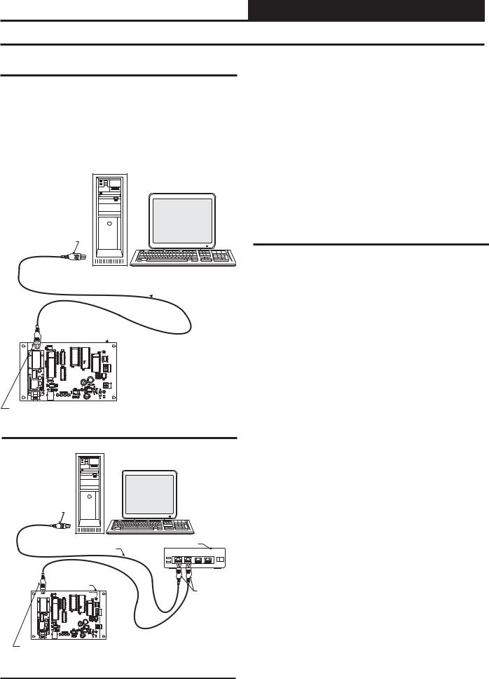
You have two options for connecting the PT-Link to your PC via Ethernet:
1.) You may connect the PT-Link directly to your PC by using a crossover cable (by others) as shown. See Figure 3 for details.
2.) You can also connect both your PC and the PT-Link to an Ethernet Hub with standard CAT5 cables. See Figure 4
for details.
Desktop Or Laptop PC
Connect Ethernet
Crossover Cable Directly
To PC Ethernet Card Port
Ethernet Crossover Cable 
Locate a CAT5 cable and plug one end into your computer’s Ethernet port (use a crossover cable if connecting directly to the PT-Link). If connecting directly, plug the other end of the Cable into the Ethernet port on the PT-Link. If connecting through an Ethernet Hub, plug the other end of the PC cable into the hub, and use a second CAT5 cable to connect the PT-Link to the hub as well.
Power up the PT-Link by plugging in the power cable. The PT-Link may take up to three minutes to power up completely. Once the PTLink is powered up, you should notice that the green “GPI05” LED light on the ProtoCessor Board remains on continuously. See Figure 19 on page 12 for a diagram showing the location of the ProtoCessor “GPI05” LED.
Computer IP Address Set-up for Windows 98, NT, and XP
In order for the PT-Link to communicate properly, it is imperative to set the IP address of both the PT-Link as well as the computer to be within the same netmask. You need to change the IP address on your computer. The following instructions will explain how to configure the IP address for Microsoft® Windows 98 and Microsoft® Windows NT and XP computers.
PT-Link Lon Board 
WattMaster |
|
EEPROM |
|
|
CONTROLS, INC |
|
EPROM |
RAM |
SERIAL # |
MADE IN THE USA |
C4 |
U1 |
|
|
|
C2 |
|
|
MM1 |
|
|
|
|
|
|
|
|
|
C1 |
|
|
|
|
ESSOR |
TRANSLATOR |
U8 |
|
|
SF000103 |
|
|
|
|
|
R3 |
X1 |
DRIVER |
C5 |
MODULE |
R4 |
RN1 |
U10 |
PAL |
|
C14 |
|
|
|
|
485 |
|||
CROTO |
|
|
|
|
|
|
|
|
|
|
R |
LOCAL |
C6 |
|
P |
|
|
|
|
C7 |
|
U4 |
|
|
|
SH |
|
|
|
|
|
|
|
|
|
C8 |
|
|
|
|
|
|
|
|
|
|
|
|
|
|
|
|
U6 |
|
|
T |
|
|
|
|
|
|
|
|
|
|
|
C10 |
|
|
|
|
|
|
|
|
|
|
|
|
|
|
U5 |
|
|
U7 |
TB1 |
||
|
|
|
|
|
|
|
|
L1 |
|
|
|
|
|
|
|
|
11.0592 |
X2 |
|
|
|
|
R6 |
R7 |
R8 |
R9 |
|
|
|
|
|
C12 |
C11 |
|
|
|
|
|
|
|
C13 |
TB3 |
|
|
|
|
U9 |
|
|
|
PROTOCESSOR |
|
D1 |
|
|
|
|
|
|
|
|
|
|
|
TRANSLATOR BOARD |
|
|
GND |
|
|
|
|||
|
|
|
|
C21 |
|
YS101982 |
|
|
|
|
|
|
|
|
|
|
|
|
C22 |
|
REV 2 |
WDOG |
C16 |
|
+24VAC |
|
|
|
|
|
|
C23 |
|
|
|
|
C17 |
|
|
|
|
|
|
|
|
|
C20 |
R2 |
|
JP3 |
U11 |
|
|
|
|
|
|
|
|
|
|
|
R1 |
RN2 |
|
|
|
D3 |
|
|
|
|
||
|
|
|
|
|
|
|
|
U12 |
|
|
|
|
|
|
|
C9 |
|
|
|
|
R17 |
R12 |
|
|
R23 |
C18 |
|
|
|
|
|
|
|
|
|
|
|
C19 |
|
|
|
|
|
|
|
|
P1 |
|
|
|
|
|
|
|
|
|
|
|
|
Connect Ethernet Crossover
Cable To PT-Link Ethernet Port
Figure 3: Connecting With Crossover Cable
Desktop Or Laptop PC
Connect Ethernet Cable
To Ethernet Hub Port
Ethernet Hub
Ethernet Cable
1 |
2 |
3 |
4 |
 Ethernet Cable
|
PT-Link Lon Board |
|
|
|
|
Connect Ethernet |
|
ESSOR |
|
Cables To |
Ethernet |
|
Hub Ports |
|
|
TRANSLATOR MODULE |
SF000103 |
|
|
CROTO |
|
R |
|
P |
|
SH |
|
|
|
T |
|
Computer IP Address Set-up for Windows 98
1.) From the Windows START button select Start-> Setting->Control panel.
2.) Double click on the Network icon.
3.) In the Configuration window, select the TCP/IP entry.
4.) Select Properties and go to the IP Address tab.
5.) Select Specify an IP address and then enter the following information:
a.) |
IP Address 192.168.1.5 |
b.) |
Netmask 255.255.255.0 |
6.) Select OK until the network configuration program exits.
7.) You might have to reboot the computer before the IP address is valid.
Connect Ethernet Cable To
PT-Link Ethernet Port
Figure 4: Connecting With Ethernet Cable & Hub
PT-Link Interface |
5 |

PT-Link-LON® Technical Guide
Configuring the PT-Link Controller
Computer IP Address Set-up for Windows NT or XP
1.) Click <start>; then click <Control Panel>.
2.) Double-click on the Network Connections icon. The Network Connections Window will appear.
Figure 5: Network Connections Window
NOTE: If any wireless connections are listed, disable them
by right-clicking the connection and selecting
<Disable>.
3.) In the Network Connections window, select the Local Area Connections entry. The Local Area Connection Status Window will appear.
4.) Click <Properties> in the lower left of the window. The Local Area Connection Properties window will appear.
Figure 7: Local Area Connection Properties Window
5). In the Connection Items list box, be sure the Internet Protocol (TCP/IP) is checked. Select the Internet Protocol (TCP/IP) item to highlight it and then click <Properties>. The Internet Protocol Properties window will appear.
|
|
|
|
|
|
|
|
|
|
|
|
|
|
|
|
|
|
|
|
Figure 8: Internet Protocol Properties Window |
|||
|
|
|
|
6). Type in the following information: |
|||
|
|
|
|
|
a.) |
IP address 192.168.1.5 |
|
|
|
|
|
||||
Figure 6: Local Area Connection Status Window |
|
|
b.) |
Subnet mask 255.255.255.0 |
|||
|
|
c.) |
Default Gateway is blank |
||||
7.) Select <OK> until all of the above network configuration windows are closed. You may have to reboot the computer before the new values are valid.
6 |
PT-Link Interface |

PT-Link-LON® Technical Guide
Configuring the PT-Link Controller
Connecting To The PT-Link
In order to communicate and program the PT-Link you will need to install RUINET software on your computer. If you do not have the software, it is available for downloading at www.orioncontrols.com in the software area of the web site. After installing the software, proceed with the following instructions.
WARNING: Make sure to load RUINET onto your hard drive and run the program from your hard drive. DO NOT under any circumstances run RUINET from your cd drive.
If RUINET is in the desktop directory (if it isn’t, locate its directory), double-click on RUINET, and the RUINET program should run. If you have only one PT-Link connected to the network, then RUINET will automatically connect to that particular PT-Link; otherwise, a menu will appear to allow the selection of the desired PT-Link.
This menu will look similar to the one shown in Figure 9.
Figure 9: RUINET PT-Link Selection Menu
Select the required PT-Link by typing the Number or Letter in the left hand column. You should now have a menu that looks like Figure 10. You are now ready to send and receive files to and from the PT-Link.
Note: If RUINET is unable to establish a connection, there are a few simple procedures you can perform to try to determine the problem. To verify your network cables, observe the “Yellow” LED displayed below “Ethernet Connection” on the PT-Link’s ProtoCessor Module. This LED should be on if the 10 BaseT cable is good. Secondly, observe the “Green” LED below “Ethernet Connection”. This LED should be solid while RUINET is running. If the LEDs are lit as expected, and RUINET still does not receive replies, then the netmask is probably incorrect. If this does not help, then your Ethernet setup on your PC is possibly not compatible. Ensure that you have an Ethernet adapter installed in your software configuration and that it is configured to run the TCP/IP protocol. If you are still unable to connect, please contact WattMaster Controls, Inc.
Making Changes to the Configuration File (config.csv)
To make changes to the configuration file on the PT-Link, use the procedures outlined that follow — Upload, Address, Poll, and Download the Configuration File.
Upload Config.csv from the PT-Link
The PT-Link contains a configuration file (config.csv) that includes information such as addressing. This file can be uploaded from the PT-Link for modification if needed. The PT-Link also contains an external interface file otherwise called an XIF file (fserver.xif). The XIF file includes information such as SNVT names and LON network information. This file can be uploaded for use with LON programming software. When uploaded, these files can be located in the same directory that the RUINET executable file is stored and run from. Be sure when uploading that the correct file is specified in the upload window. Refer to Figures 11 & 12 for screen details. Refer to Appendix B for details on uploading XIF files.
Figure 10: RUINET PT-Link Main Menu |
|
Figure 11: RUINET PT-Link Main Menu - Upload |
PT-Link Interface |
7 |

PT-Link-LON® Technical Guide
Configuring the PT-Link Controller
From the Main Menu, type “U”.The menu shown in Figure 12 will appear.
Figure 12: RUINET PT-Link Uploading Files
1.) Begin the upload by pressing “U.”
2.) When the upload is completed, open the uploaded file with Microsoft® Notepad. This program is supplied with Microsoft® Windows. Type “N” to open using Notepad.
WARNING: Only edit the config.sys file using Notepad. Do not use Excel. Using Excel to edit the config.sys file will corrupt its contents!
Explicit and Implicit Addressing
Clients can address the PT-Link using explicit or implicit addressing. Clients using explicit addressing obtain their data transfer parameters directly from the PT-Link-LON configuration file (config.csv). Implicit addressing is used when a Network ManagementTool such as LonMaker® is used to connect a PT-Link-LON to other LonWorks nodes—the PT-Link-LON is assigned its data transfer (binding) parameters by the Network Management Tool.
NOTE: The PT-Link-LON is configured from the factory to use implicit addressing.
Implicit Addressing — Network Manager assigns addresses for communication and ensures (via address tables in the devices) that communication connections are known.
Explicit Addressing — Device knows the address of the point in the remote device and communicates directly without the assistance of the Network Manager.
Implicit Addressing Commissioning Using
LonMaker
1.) Ensure that the correct firmware and latest configuration is loaded on the PT-Link-LON.
NOTE: Each change in the PT-Link-LON requires re-commis- sioning of the PT-Link-LON in LonMaker.
2.) Ensure that the PT-Link-LON and the LonMaker machine are on the same network.
3.) Open the existing Network in LonMaker or create a new Network.
4.) Click on “Create New Network” and follow the network wizard, making the following selections:
Network Interface: Choose Network Attached Management Mode: Choose Onnet unless you are working offline
Registered Plug-ins required: None
5.) Once Visio is open with the Network showing, drag a new device onto the drawing from the toolbox.
6.) Follow the Device Network, making the following selections:
Enter Device Name: Choose commission device Specify Device Template: Choose upload from device
Specify Device Channel: Choose Auto Detect
Specify Device Properties: Leave as is (Ping is optional) Identify Device: Choose service pin
Device Application Image: Leave unchecked Initial State: Leave as is
7.) Press the service pin on the PT-Link-LON when asked to do so, and the PT-Link-LON will be commissioned.
8.) Drag a new function block onto the drawing from the toolbox. Give the function block a name and ensure that it is allocated to the PT-Link-LON device.
9.) Once the function block is on the drawing, you can drag input and output variables onto the function block. When you do this, LonMaker will show you the variables available for binding. Click on the variables you require (or use the select “all” option), and they will be commissioned onto the function block.
10.) You are now ready to connect these variables to other devices by dragging connections from the toolbox and connecting the variables.
8 |
PT-Link Interface |
PT-Link-LON® Technical Guide
Troubleshooting the PT-Link Controller
Explicit Addressing & Domain Table Setup
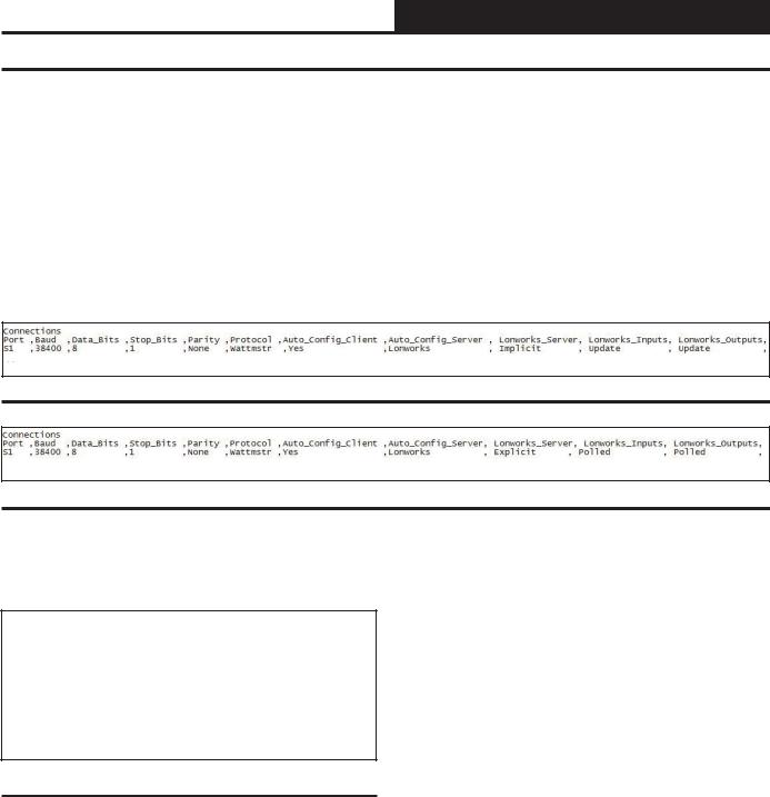
To use explicit addressing, the client needs to change the factory settings contained in the PT-Link-LON’s configuration file (config.csv). The following are the steps to change the configuration file from implicit to explicit addressing:
1.) Upload and open the config.csv file. 2.) Locate the “Connections” section.
3.) Locate the “Lonworks_Server” column and change the value from “Implicit” shown in Figure 13 to “Explicit” shown in Figure 14. You should also change the “Lon works _Input” and “Lonworks_Outputs” from Update to Polled.
Figure 13: PT-Link-LON Implicit Configuration
Figure 14: PT-Link-LON Explicit Configuration
In addition, the PT-Link-LON must have its domain, subnet, and node IDs set. This feature is enabled in the configuration file by filling out the Title and System_Address fields of the PT-Link-LON parameters as follows:
//==================================================
//
// Common Information
//
Bridge System_Address ,Title
23 |
,”:D48:S01:Wattmaster Explicit Lon v1.00d” |
Figure 15: PT-Link-LON Domain and Subnet Setting
The Title field must start with “:D”, followed by the domain_id in hexadecimal notation, followed by “:S”, followed by the subnet_id in hexadecimal notation, and enclosed by “:”. The domain length is automatically determined by the number of digits in the [domain_id] field. With 2 hexadecimal digits constituting 1 byte, “:D123456:”, for example, would have a length of 3.
Once the domain table has been set, the “:Dxx:Sxx:” part of the Title field will be removed.
Now the Title field will be left with [Title continued…] which may be the Node self documentation string or any title.
After the changes are done, do not forget to save the file, download the new configuration file, and restart the PT-Link-LON. Refer to the Download Section that follows.
PT-Link Interface |
9 |
PT-Link-LON® Technical Guide
Troubleshooting the PT-Link Controller
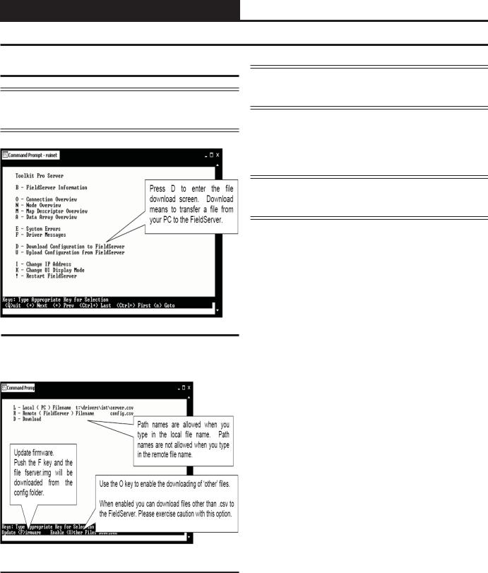
Download Config.csv to the PT-Link
NOTE: Before attempting to send files to the PT-Link, make sure that these files are in the same directory as the RUINET utility being used for sending.
NOTE: The utility will indicate when downloading is complete. DO NOT reset the PT-Link until this message is displayed, as this will corrupt the PT-Link.
2.) Once the download is complete, push <Esc> to get back to the main menu and use the “!” option (or simply cycle power to the PT-Link) to put the new file into operation. It is possible to do multiple downloads to the PT-Link before resetting it.
NOTE: The Remote Filename option must always be named “config.csv” for configurations; otherwise, they will be ignored by the PT-Link.
Figure 16: RUINET PT-Link Main Menu - Download
From the Main Menu, type “D”.The menu shown in Figure 17 will appear.
Figure 17: RUINET PT-Link Downloading Files
1.) Begin the download by selecting “D.”
10 |
PT-Link Interface |
PT-Link-LON® Technical Guide
Troubleshooting the PT-Link Controller
PT-Link Board LEDs
The PT-Link-LON® is equipped with LEDs that can be used for troubleshooting. There are four LEDs on the PT-Link board. See Figure 18 for the locations of the LEDs on the PT-Link board. The LED descriptions and functions are listed in the following paragraphs.
PWR LED
When the PT-Link-LON® is powered up, the “PWR” LED should light up and stay on continuously. If it does not light up, check to be sure that you have 24 VAC connected to the board, that the wiring connections are tight, and that they are wired for correct polarity. The 24 VAC power must be connected so that all ground wires remain common. If after making all these checks the “PWR” LED still does not light up, please contact WattMaster Controls Technical Support at our Toll Free number—866-918-1100—for assistance.
LOOP LED
When power is applied to the PT-Link-LON®, the “LOOP” LED will also light up. The LED should flicker rapidly, indicating that the PT-Link is trying to communicate with the controllers on the loop. A “flicker” is defined as a brief moment when the LED turns off and back on. If the “LOOP” LED does not operate as indicated above, first power down the unit and then reapply power. If this does not work, please contact WattMaster Controls Technical Support at our Toll Free number—866- 918-1100—for assistance.
LED 1
When power is first applied, “LED 1” will be off temporarily and then will blink once if it is communicating with the controller. If the LED is not blinking, there is a communication problem between the HVAC controller and the PT-Link board. The “COMM” LED on the HVAC controller also should be solid and will flicker occasionally indicating communication with the PT-Link-LON®. If the “COMM” LED does not flicker, then there is no communication between the PT Link and the controller.
LED 2
When power is first applied, “LED 2” will be off temporarily and then will blink slowly indicating that the PT-Link baseboard is communicating with the Protocessor Module. If “LED 2” does not blink, check that the Protocessor Module is installed correctly in the PT-Link baseboard.
PT-Link Base
Board
LED2 |
PWR |
LED1 |
LOOP |
Figure 18: PT-Link-LON® LED Locations
PT-Link Interface |
11 |

PT-Link-LON® Technical Guide
Troubleshooting the PT-Link Controller
ProtoCessor Module LEDs
PWR LED
When the PT-Link is first powered up, the “PWR” LED should light up and stay on continuously. See Figure 19. If the LED doesn’t light up, check that the ProtoCessor is installed correctly and firmly connected to the Base Board.
GPI05 LED
The “GPI05” LED will light up when the Base Board and the ProtoCessor Module have established communications. This can take up to 3 minutes depending on the number of units connected to the PT-Link. If it fails to light up after 3 minutes, check that the ProtoCessor is installed correctly and firmly to the Base Board.
LON LED
When the unit is first powered up, before commissioning has occurred, this LED will be blinking to indicate the unit has not been commissioned yet. Once the unit is commissioned, the LED will stay off during normal operations.
LA LED
When the unit is first powered up, this LED should be blinking constantly. If this LED is constantly on or constantly off, the Module is not working properly and needs to be replaced.
TX & RX LEDs
These LEDs work together to indicate that communication is being established with the desired protocol network. If both LEDs are blinking, then communication is working properly. If both are not blinking, check the protocol network wiring.
If all of these tests are made and the controller still doesn’t operate, please contact WattMaster Controls Technical Support at our Toll Free number—866-918-1100—for assistance.
Protocessor
LON
GPI05
PWR 
 LA
LA

 TX
TX  RX
RX
 LON
LON
Figure 19: PT-Link-LON® LED Locations
12 |
PT-Link Interface |
 Loading...