


instruction Manual
Orion StarBlast™ 6/6i
IntelliScope Reflector
#10016 / #27191
OrionTelescopes.com
Customer Support (800) 676-1343
E-mail: support@telescope.com
|
Corporate Offices (831) 763-7000 |
Providing Exceptional Consumer Optical Products Since 1975 |
89 Hangar Way, Watsonville, CA 95076 |
IN 377 Rev. D 08/13

Navigation knob
EZ Finder II reflex sight
Focuser
|
|
|
|
|
|
|
Sirius Plössl |
||||||||||||
|
|
|
|
|
|
|
eyepiece |
||||||||||||
|
|
|
|
|
|
|
|
|
|
|
|
Tube rings |
|||||||
|
|
|
|
|
|
|
|
|
|
|
|
||||||||
|
|
|
|
|
|
|
|
|
|
|
|
|
Altitude |
||||||
|
|
|
|
|
|
|
|
|
|
|
|
|
|||||||
|
|
|
|
|
|
|
|
|
|
|
|
|
|||||||
|
|
|
|
|
|
|
|
|
|
|
|
|
tensioning knob |
||||||
Focus wheels |
|
|
|
|
|
|
|
|
|
|
|
|
|
|
Bottom end ring |
||||
|
|
|
|
|
|
|
|
|
|
|
|
|
|
|
|
|
and primary |
||
|
|
|
|
|
|
|
|
|
|
|
|
|
|
|
|
|
mirror cell |
||
Optical tube |
|
|
|
|
|
|
|
|
|
|
|
|
|
|
|
|
|
||
assembly |
|
|
|
|
|
|
|
|
|
|
|
|
|
|
|
|
|
||
|
|
|
IntelliScope |
||||||||||||||||
|
|
|
Computerized |
|
|
|
|
|
|
|
|
|
|
|
|||||
|
|
|
|
|
|
||||||||||||||
|
|
|
Object Locator |
||||||||||||||||
|
|
|
|
|
|
|
|
|
|
|
|
|
|
|
|
|
Eyepiece |
||
|
|
|
|
|
|
|
|
|
|
|
|
|
|
|
|
|
rack |
||
Vertical stop |
|
|
|
|
|
|
|
|
|
|
|
|
|
|
|
|
|
Carrying |
|
|
|
|
|
|
|
|
|
|
|
|
|
|
|
|
|
|
handle |
||
|
|
|
|
|
|
|
|
|
|
|
|
|
|
|
|
|
|
|
|
Carrying handle |
|
|
|
|
|
|
|
|
|
|
|
|
|
|
|
|
|
Altazimuth |
|
|
|
|
|
|
|
|
|
|
|
|
|
|
|
|
|
|
|||
|
|
|
|
|
|
|
|
|
|
|
|
|
|
|
|
|
|
|
|
Top baseplate |
|
|
|
|
|
|
|
|
|
|
|
|
|
|
|
|
base |
||
|
|
|
|
|
|
|
|
|
|
|
|
|
|
|
|
|
|||
|
Bottom baseplate |
|
|
|
|
|
|
|
|
|
|
|
|||||||
|
|
|
|
|
|
|
|
|
|
|
|
||||||||
|
|
|
|
||||||||||||||||
Figure 1. The StarBlast 6/6i, shown with IntelliScope system installed (#27191)
2

Congratulations on your purchase of an Orion StarBlast 6/6i IntelliScope Reflector telescope! It is a versatile and compact astronomical instrument designed to provide wondrous views of celestial objects while offering unprecedented ease of use.
These instructions apply to both the StarBlast 6 (#10016, without IntelliScope Computerized Object Locator) and the StarBlast 6i (#27191), which includes the IntelliScope system. If you purchased the StarBlast 6 (#10016), you may always add the IntelliScope system (#27926) later to enjoy full digital object location capability.
NOTE: The original model of the StarBlast 6 (#9964) is not compatible with the IntelliScope Computerized Object Locator.
If you purchased the #10016 StarBlast 6, you will enjoy breathtaking views of the Moon, planets, and even deep-sky objects like the Orion Nebula. The telescope’s precision Newtonian optics; portable, user-friendly design; and complement of outstanding features and accessories will make stargazing easy and fun for the whole family.
If you purchased the #27191 StarBlast 6i IntelliScope, viewing the night sky will be even easier, as you will have the ability to pinpoint and view thousands of celestial objects with the push of a button. Searching for objects will not be necessary because the IntelliScope’s high-resolution digital encoders will find them for you, in seconds!
Either way, we hope you enjoy your journey through the universe!
These instructions will help you set up and use your StarBlast 6/6i telescope, please read them thoroughly.
Warning: Never look at the sun with your telescope (or even with just your eyes) without a professionally made solar filter. Permanent eye damage or blindness could result. Young children should use this telescope only with adult supervision.
Avoid using the type of solar filter that screws into an eyepiece. They are susceptible to cracking under the intense heat that builds up near the focus point, and could cause severe retinal damage. Use only the type of solar filter that covers the front of the telescope. Also, be sure to leave the cover caps on the finder scope when solar observing. Better yet, remove the finder scope altogether when viewing the sun.
Table of Contents
1. |
Unpacking . . . . . . . . . . . . . . 4 |
|||
2. |
Parts List . . . . . . . . . . . . . . 4 |
|||
3. |
Assembly of #10016 StarBlast 6 |
|
|
|
|
(without IntelliScope system) . . . . . . |
. |
. |
. 6 |
4. |
Assembly of #27191 |
|
|
|
|
StarBlast 6i IntelliScope . . . . . . |
. |
. |
. 6 |
5. |
Final Assembly of Your Telescope |
|
|
|
|
(StarBlast 6/6i) . . . . . . . . . . . . 11 |
|||
6. |
Preparing to Use Your Telescope . . |
. |
. |
. 12 |
7. |
Observing With Your Telescope . . . |
. |
. |
13 |
8. |
Using the IntelliScope Computerized |
|
|
|
|
Object Locator . . . . . . . . . |
. |
. |
. 16 |
A.Alignment . . . . . . . . . . . . 16
B.Overview of the IntelliScope Computerized Object Locator . . . . 18
C. |
Locating the Planets . . . |
. |
. |
. |
. |
. 19 |
D. Locating Deep-Sky Objects |
|
|
|
|
|
|
|
by Catalog . . . . . . . |
. |
. |
. |
. |
. 20 |
E. Locating Deep Sky Objects |
|
|
|
|
|
|
|
by Object Type . . . . . . |
|
. . . . 21 |
|||
F. |
Locating Stars . . . . . . |
|
. . . . 22 |
|||
G. |
Tours of the Best Objects . . |
|
. . . . 23 |
|||
H. |
The Identify Function . . . |
. |
. |
. |
. |
. 23 |
I.Adding User-Defined Objects . . . . 24
J.The Function (FCN) Button . . . . . 24
K. The “Hidden” Functions . . . . . . . 25
9.Care and Maintenance . . . . . . . . 26
10.Specifications of the StarBlast 6/6i . . . . 27
11.Specifications of the IntelliScope System . 27 Appendix A: Collimating the Optics . . . . . 28 Appendix B: Cleaning the Optics . . . . . . 31
Appendix C: Troubleshooting the
IntelliScope System . . . . . . . . . . 31 Appendix D: Alignment Star Finder Charts . . 34 Appendix E: Constellation Abbreviations . . . 38 Appendix F: ST Catalog . . . . . . . . . . . . . . . . . . . 39
3

Top of base side panel
Rotate
Telescope mounting bracket
Figure 2. To remove the cardboard insert from atop the altazimuth base, rotate the telescope mounting bracket so its long axis is vertically oriented, then lift the insert off.
1. Unpacking
Carefully unpack the StarBlast 6/6i from its shipping box. We recommend keeping the original shipping box and any smaller accessory boxes contained within it. In the event that the telescope needs to be shipped to another location, or returned to Orion for warranty repair, having the proper shipping containers will help ensure that your telescope will survive the journey intact.
To remove the foam insert from the top of the altazimuth base, rotate the telescope mounting bracket so that its long axis is oriented vertically, then lift the foam insert out of the box (Figure 2).
Make sure all the parts in the Parts List below are present. Be sure to check the boxes carefully, as some parts are small. If anything appears to be missing or broken, immediately call Orion Customer Support (800-676-1343) for assistance.
1 EZ Finder II reflex sight
1 Collimation cap
1 3-Hole eyepiece rack
1 Hex key, or Allen wrench (size 3/16")
The following parts are packed in small plastic bags inside the main telescope box. They are needed only for the StarBlast 6i IntelliScope model (#27191), not for the StarBlast 6 (#10016) without IntelliScope. If you purchased the latter, please do not discard these parts! Should you decide at a later date to add the IntelliScope Computerized Object Locator (#27926), you will need these parts. Keep them in a safe place.
1 Azimuth encoder board
1 Azimuth encoder disk
1 Vertical stop L-bracket
1 Vertical stop bolt (with knob)
2. Parts List
1 Jam nut for vertical stop bolt
Qty. Description
1 Brass azimuth bushing
1 Optical tube assembly
1 Aluminum spacer ring
1 Altazimuth base
3 Machine screws, 5mm (<1/4") long
1 Tube rings, pair
6 Wood screws, 12mm (~½") long
1 Optical tube dust cover
2 Machine screws, 25mm (~1") long
1 25mm Sirius Plössl eyepiece,
2 Small hex nuts (for 25mm machine screws)
1 10mm Sirius Plössl eyepiece
2 Small flat washers (for 25mm machine screws)
2 Small lock washers (for 25mm machine screws)
4

Hex lock nut
Fender washer
Top baseplate 
Washer
Wood screw 

Modular jack
Azimuth
bearing pads  (x3)
(x3)
Short azimuth bushing 

Fender washer 

Azimuth axis bolt 

 Vertical side panel
25mm (~1") machine screws
Vertical stop
L-bracket
Pre-drilled holes


 Lock washers
 Hex nuts
Wave spring
Azimuth encorder board
Brass azimuth bushing
Azimuth encoder disk
 Bottom baseplate
Figure 3. Illustration showing correct placement of the azimuth components of the IntelliScope system on the altazimuth base.
5

|
Azimuth axis bolt |
|
|
|
|
PTFE/ |
|
|
|
|
UHMW |
|
|
|
|
bearing |
|
|
|
|
ring |
|
Altazimuth |
|
|
|
|
|
|
Fender |
|
|
encoder jack |
Vertical |
Long |
|
|
stop knob |
|
washers |
|
|
||
azimuth |
|
|
|
|
|
|
|
|
|
|
bushing |
|
|
Vertical stop |
|
|
|
|
|
|
|
|
|
L-bracket |
|
Short |
|
Azimuth bolt |
Jam |
|
|
nut |
||
|
azimuth |
|
||
Lock nut |
|
lock nut |
|
|
bushing |
|
|
||
|
|
|
|
|
|
|
|
|
|
Figure 4. When you disassemble the top and bottom baseplates, you should see all of these parts.
Figure 5. The vertical stop L-bracket and bolt (with knob), shown installed in their correct orientations. The jam (hex) nut on the opposite side of the L-bracket from the knob locks the vertical stop bolt in the desired position.
The following parts are included in the small box containing the IntelliScope Computerized Object Locator that comes with the StarBlast 6i IntelliScope model (#27191) only. They are not included or needed with the standard StarBlast 6 (#10016).
1Computerized Object Locator
1Altitude encoder board
1Encoder connector board
1Altitude encoder disk
1Coil cable
1Altitude encoder cable (shorter)
1Azimuth encoder cable (longer)
1Wood screw, ½" long
8Washers, 5/16" diameter
1Wave spring
1Compression spring
4Cable retaining clips
2Hook-and-loop strips (1 “hook” strip, 1 “loop” strip) 9-volt battery
3.Assembly of #10016
StarBlast 6 (without IntelliScope system)
The StarBlast 6/6i is partially assembled at the factory, for your convenience. The altazimuth base is fully pre-assembled in the #10016 configuration; that is, it is ready for use without the IntelliScope system. If you purchased the #10016 StarBlast 6, please skip to section 5: “Final Assembly of Your Telescope (StarBlast 6/6i).”
4.Assembly of #27191 StarBlast 6i IntelliScope
If you purchased the #27191 StarBlast 6i IntelliScope, some assembly is required to install the components of the IntelliScope system on the altazimuth base. In fact, you will first have to disassemble a portion of the base to remove a couple of parts and install others that are necessary for the IntelliScope system of function properly.
Installation of the IntelliScope System on the Altazimuth Base
The assembly requires a small and a medium-sized Phillips screwdriver and two adjustable crescent wrenches. You can substitute a pair of pliers for one of the adjustable crescent wrenches. You will also need a small (4" or so) piece of duct tape, masking tape, or packing tape.
When tightening screws, tighten them until firm, but be careful not to strip the threads by over-tightening.
Begin by placing the pre-assembled altazimuth base on the floor or a table. For steps 1-11, refer to the schematic illustration in Figure 3 for correct placement of components.
1.To prepare the base for the installation of the IntelliScope system components, you must first disassemble the top baseplate from the bottom baseplate. To do this, use one adjustable crescent wrench or a pair of pliers to hold the hex head of the azimuth axis bolt steady on the underside of the bottom baseplate while using another adjustable crescent wrench to turn the hex lock nut
on the other end of the bolt. Remove the lock nut and metal fender washer and set them aside. Now carefully separate the two baseplates. In addition to the azimuth axis bolt and a fender washer on the underside of the
6

Under side of top baseplate |
|
|
|
Pre-drilled |
|
|
|
starter hole |
Center hole |
|
Wave |
|
|
|
|
|
|
Altazimuth encoder board |
spring |
|
|
|
|
Wood screw |
|
|
|
Washer |
Modular jack |
|
|
|
|
|
|
Under side of top baseplate
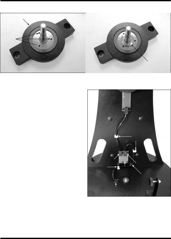
Figure 6. Install the azimuth encoder board on the under side of the top baseplate. Be sure to place one washer on the screw after inserting the screw through its hole in the azimuth board, then thread the screw into the predrilled starter hole.
bottom baseplate, you should also see three white plastic parts: a short azimuth bushing, a long azimuth bushing, and a flat PTFE/UHMW bearing ring (Figure 4). The bushings may have remained lodged in the center hole of the baseplate(s) when you removed it. If that’s the case, use a finger to push the bushing out of the hole. Set the bottom baseplate and associated parts aside for now while you install the vertical stop L-bracket on the top baseplate.
2.Install the vertical stop L-bracket. It will be permanently installed on the top baseplate (Figure 5). The vertical stop L-bracket will be used before each observing session to set the precise vertical orientation of the optical tube, the procedure for which will be described later. Once installed, the L-bracket will never have to be removed because it does not interfere with the range of motion of the optical tube between vertical and horizontal positions.
To install the vertical stop L-bracket, insert the two 25mm (~1") machine screws through the two holes in the L-bracket’s foot. Then insert the screws into the holes in the top baseplate, with the L-bracket oriented as shown in Figure 5. On the underside of the top baseplate, place a small lock washer on the end of each screw, then thread on a small hex nut. While holding the hex nut stationary with two fingers, tighten the screw with a small Phillips screwdriver. Repeat for the other screw. Now the L-bracket is secured in place.
Note: You may discard the two small flat washers for the 25mm machine screws that were included in the hardware kit; they are not needed.
Figure 7. Wedge the wave spring between the azimuth encoder board and the baseplate and align the “hole” in the wave spring with the central hole in the baseplate.
3.Thread the vertical stop bolt and knob into the corresponding hole in the vertical stop bracket, in the orientation show in Figure 5. Thread it though so that 1/2" or so of the bolt emerges on the other side of the L-bracket, then thread on the jam nut. You will adjust the position of the vertical stop bolt and tighten the jam nut later, when initializing the IntelliScope system prior to using it for the first time.
4.Attach the azimuth encoder board to the underside of the top baseplate (Figure 6). Insert a wood screw through the slot in the azimuth encoder board, then place a washer over the tip of the screw. Now hold the encoder board so that the modular jack and large hole in the encoder board line up with their corresponding holes
in the baseplate. Insert the screw tip into the pre-drilled starter hole and screw it in with a Phillips screwdriver until just tight. The screw should not be fully tightened; it should be tight, but not tight enough to prevent the encoder board from moving in its slot.
5.Place the wave spring between the azimuth encoder board and the bottom of the top baseplate as shown in Figure 7. Position the wave spring so that it aligns precisely with the central hole in the baseplate.
Now that the azimuth encoder is installed on the underside of the top baseplate, be sure not to set the baseplate down on a flat surface, as doing so could damage the encoder. Rather, set the baseplate with attached vertical side panel assembly on its side for now.
6.Place one fender washer on the azimuth axis bolt, followed by the short nylon bushing. Then insert the bolt through the central hole from the underside of the bottom
7

Under side of bottom
baseplate Head of azimuth axis bolt (and fender washer)
Tape
Figure 8. Placing a piece of duct, masking, or packing tape over the hex head of the azimuth axis bolt will keep it from dropping downward when you replace the top baseplate onto the bottom baseplate.
baseplate. Make sure the short nylon bushing seats up into the hole.
7.Now temporarily place a piece of duct tape, masking tape, or packing tape over the head of the azimuth axis bolt (Figure 8). This will keep the bolt from sliding down as you install the top baseplate, which you will do in step 10.
8.Place the azimuth encoder disk, flat side down, over the azimuth axis bolt and rest it on the bottom baseplate. Make sure you’ve got the correct encoder disk! The azimuth encoder disk has a smaller center hole than the altitude encoder disk.
9.Place the brass bushing onto the azimuth axis bolt so that the wide end of the bushing is closest to the encoder disk. Seat the bushing onto the encoder disk so that the registration feature on the bushing goes into the hole in the encoder disk. You may need to move the encoder disk around on the azimuth axis bolt a bit for the bushing to seat properly.
Note that for the IntelliScope version (#27191) of this telescope, you will not need the long nylon azimuth bushing and PTFE/UHMW bearing disk that you removed during the baseplate disassembly (Figure 4). Those parts are only utilized for the non-IntelliScope version of the StarBlast 6 (#10016).
10.Carefully position the top baseplate over the bottom baseplate and lower it so the brass bushing goes up into
Figure 9. To reassemble the baseplates, tilt them only slightly, as shown. Do not place them on their side. Use one wrench to hold the azimuth axis bolt head steady while turning the hex lock nut with the other wrench.
the center hole of the top baseplate. Place the remaining fender washer onto the shaft of the azimuth axis bolt, then thread the hex lock nut onto the end of the bolt and tighten it only finger tight, for now. Note that the brass bushing protrudes slightly above the surface of the top baseplate. This is by design.
11.Tilt the assembled base at a slight angle (as little as possible) and remove the tape from underneath the bottom baseplate. Now, with one wrench (or pliers) hold the head of the azimuth axis screw still while turning the hex lock nut with the other wrench (Figure 9). Tighten the hex lock nut just until the top fender washer is no longer loose, then tighten the hex nut 3/16 to 1/4 turn beyond that. This ensures proper spacing between the encoder disk and the azimuth encoder board.
12.Attach the encoder connector board to the side panel. Place a wood screw into each of the four holes of the connector board and then a washer onto each screw. Sliding the washers all the way down on the screw shaft should help keep the screws from falling out while installing the board. Still, the installation may take a bit of dexterity, so don’t get frustrated if it takes a couple tries. Align the screw tips with the four pre-drilled holes in the side panel so that the modular jack fits into the
rectangular cutout. Then thread the screws into the holes with a screwdriver. See Figure 10.
8

Figure 10. Installing the encoder connector board. There is a washer on each screw, between the encoder board and the side panel.
13.To attach the altitude encoder board and altitude encoder disk, you must first remove the telescope mounting bracket. Rotate the altitude axis tensioning knob counterclockwise and remove it completely. You’ll see two flat washers and a ball bearing ring remaining on the mounting bracket’s shaft. To remove them you have to rotate the outer washer counterclockwise to “unthread”
it from the bolt shaft, then slide the ball bearing ring and inside washer off of the shaft. Now remove the telescope mounting bracket from the side panel.
14.Insert the compression spring into the hole just below the hole for the altitude axis bolt on the inside surface of the side panel. When inserted as far as it will go, the spring will still protrude from the hole by several millimeters (Figure 11).
15.Now you will install the altitude encoder board. Place two wood screws through the mounting holes in the board, and then place two washers over the screw tips as shown in Figure 12a. Thread the screws into the predrilled mounting holes with a Phillips screwdriver until the board is secured, making sure that the large hole in the encoder board is aligned with the hole in the side panel and the board is pressing squarely against the
compression spring that you installed in the previous step (Figure 12b). The screws should not be fully tightened; they should be tight, but not tight enough to prevent the altitude encoder from moving up and down within the slots in the encoder board.
Compression spring
Figure 11. Insert the compression spring into the small hole just below the larger hole for the altitude axis bolt.
Altitude encoder board
Washers
 Wood screws
a
b
Figure 12. (a) Installing the altitude encoder board. Place a washer on each screw, as shown. (b) The altitude encoder board installed.
9
Telescope mounting bracket
5mm
machine
screws  Altitude
  encoder disk
Aluminum spacer ring
a |
b |
Figure 13. (a) The altitude encoder disk is attached to the telescope mounting bracket with three 5mm machine screws. The disk fits just inside the Ebony Star bearing ring. (b) The aluminum spacer ring should be installed on the telescope mounting bracket’s shaft (altitude axis bolt) such that the flat side of the ring faces outward.
16.Attach the altitude encoder disk to the telescope mounting bracket with the three 5mm (~1/4") machine screws (Figure 13a). Place the aluminum spacer ring on the telescope mounting bracket shaft with the flat side of the ring facing outward (the opposite side has an indentation around the hole). See Figure 13b. Then carefully insert the shaft through the hole in the altitude encoder board and then the hole in the side panel. You may have to carefully rotate the shaft back and forth a little to get it through the hole, as it is a tight fit. Slide the inside washer and ball bearing ring (which you removed in step 13) onto the shaft, then “thread on” the outer washer followed by the altitude tensioning knob.
17.Lastly, connect the encoder cables and install the cable retaining clips. Refer to Figure 14 for proper placement. Connect one end of the azimuth encoder cable (the longer of the two cables) to the encoder jack in the
top baseplate. Connect the other end to the encoder connector board on the side panel. The cable should plug into the jack on the right side of the encoder connector board.
Plug one end of the altitude encoder cable into the modular jack on the altitude encoder board. Connect the other end of the cable to the jack on the left side of the encoder connector board.
Use the provided cable retaining clips to secure the altitude and azimuth cables neatly to the base. We recommend using one clip for the (shorter) altitude cable, and two clips for the (longer) azimuth cable (Figure 14). The clips have adhesive backing; simply peel the paper off the back of the clip and press the adhesive back to the base where you want the clip to be located.
Altitude  encoder
board
Altitude encoder 
cable Cable clips
Altitude |
|
|
|
cable jack |
|
Azimuth |
|
Cable |
Encoder |
cable jack |
|
|
|||
clip |
|
||
connector |
Azimuth |
||
|
|||
|
board |
encoder cable |
Azimuth encoder board jack
Figure 14. Connect the two encoder cables as shown.
10
|
|
Telescope |
|
|
mounting |
Tube ring |
bracket |
|
|
|
Flat |
|
|
|
|
|
washer |
Lock |
Socket head |
washer |
cap screw |
Hex key
Figure 15. Attaching a tube ring to the telescope mounting bracket.
5.Final Assembly of Your Telescope (StarBlast 6/6i)
Now you will complete the assembly of your telescope by installing the tube rings and optical tube assembly on the altazimuth base and attaching the included accessories.
Before getting started, locate the following items:
Qty. Description
1Optical tube assembly
2Tube rings
1Telescope mounting bracket
1EZ Finder II reflex sight
125mm Sirius Plössl eyepiece
110mm Sirius Plössl eyepiece
1Eyepiece rack
2Socket-head cap screws w/washers (on tube rings)
Attach the Optical Tube to the Base
To attach the optical tube assembly to the altazimuth base you will first need to equip the telescope mounting bracket with the two tube rings. Rotate the bracket so one of the two through holes in the bracket is accessible (Figure 15). Place a lock washer and then a flat washer onto each of the socket-head cap screws. Then insert the screw into the through hole as shown in Figure 15 and thread it into one of the two tube rings using the included hex key. Do not tighten it all the way; you’ll do that after the telescope tube has been secured in the tube rings. Now rotate the bracket 180° so the other through hole is accessible. Fasten the second tube ring to the bracket with the remaining washer-equipped screw using the hex key. Again, don’t tighten the screw completely yet. Be sure to orient the
Front (open) end of optical tube
 Dovetail
base
 Thumbscrew
Figure 16. Attach the EZ Finder II in its dovetail base in the orientation shown.
tube rings so that the knurled ring clamps are on the same side.
Open the tube rings by loosening the knurled ring clamps. Place the optical tube assembly in the open rings so the front (open) end of the tube points upward. While grasping the optical tube firmly, close the rings around the tube and loosely tighten the knurled ring clamps. Adjust the position of the optical tube in the tube rings so the bottom end of the tube just clears the hardware in the center of the top baseplate.
To view through the StarBlast 6/6i comfortably, you can adjust the orientation of the focuser by rotating the optical tube within the tube rings. Loosen the knurled ring clamps on the tube rings by a few turns. Now, gently rotate the optical tube within the tube rings until the focuser is oriented to your liking. Then tighten the knurled ring clamps to secure the optical tube in that position.
Now that the optical tube is secured tightly in the tube rings, tighten up each of the two socket-head cap screws that fasten the tube rings to the telescope mounting bracket using the hex key.
Install the EZ Finder II Reflex Sight
Slide the foot of the EZ Finder II bracket into the dovetail base that is pre-installed on the optical tube (Figure 16). The EZ Finder II should be oriented as in the figure. Tighten the thumbscrew on the dovetail base to secure the EZ Finder II in place. If it is present, remove the thin plastic battery shield tab (not shown) from the battery casing prior to use and discard it.
Install the Eyepiece Rack
The eyepiece rack can be installed so that it can be removed, or so it is permanently attached. Place the large portion of the eyepiece rack’s “keyhole” mounting slots over the two preinstalled Phillips head screws on the side of the altazimuth base, then slide the rack downward. If you want to be able to remove the rack for transport or storage of the telescope, be sure the screws are loose enough so you can lift the rack and remove it from the base through the large opening of the “keyhole.” If you wish to permanently attach the rack to the
11

base, tighten the two screws with a screwdriver until the rack is secured in place.
Insert an Eyepiece
Remove the small cap covering the focuser drawtube and loosen the two eyepiece locking thumbscrews on the drawtube collar. Insert the chrome barrel of the 25mm Sirius Plössl eyepiece into the focuser and secure it with the thumbscrews. You can place the 10mm Sirius Plössl eyepiece in the eyepiece rack for use later.
Congratulations! Your telescope is now fully assembled. Remove the dust cap from the front of the telescope when it is in use. Replace it when you are finished observing.
6.Preparing to Use Your Telescope
This section applies to both the StarBlast 6 (#10016) and StarBlast 6i IntelliScope (#27191).
It’s best to get a feel for the basic functions of the StarBlast 6/6i during the day, before observing astronomical objects at night. This way you won’t have to orient yourself in the dark! Find a spot outdoors where you’ll have plenty of room to move the telescope, and where you’ll have a clear view of some object or vista that is at least 1/4 mile away. It is not critical that the altazimuth base be exactly level (except when initially setting the vertical stop knob position on the StarBlast 6i IntelliScope), but it should be somewhat level to ensure smooth movement.
The StarBlast 6/6i was designed specifically for visual observation of astronomical objects in the night sky. Like all Newtonian reflector telescopes, it is not well suited for daytime terrestrial usage because the image in the eyepiece will be rotated somewhat from the normal, naked-eye view.
Placing the StarBlast 6/6i for Comfortable Viewing
One of the great assets of the StarBlast 6/6i is its extremely portable size. Due to its overall short length, you will find that viewing while sitting next to the telescope is the most comfortable. If you wish to raise the telescope off the ground so that it can be used while standing or sitting in a chair, then a platform, such as a milk crate, sturdy table, or the hood of a car can be used.
Altitude and Azimuth (Aiming the Telescope)
The StarBlast 6/6i’s altazimuth base permits motion along two axes: altitude (up/down) and azimuth (left/right). See Figure 17. Moving the telescope up/down and left/right is the “natural” way people aim objects, which makes pointing the telescope intuitive and easy.
Simply take hold of the navigation knob and push or pull it to move the telescope and base in the desired direction. Both the altitude and azimuth motions can be made simultaneously and in a continuous manner for easy aiming. This way you can point to any position in the night sky, from horizon to horizon.
Altitude
Azimuth
Figure 17. The StarBlast 6/6i has two axes of motion: altitude (up/down) and azimuth (left/right).
You may find it convenient to hold one hand on one of the carrying handles to help in leveraging the base while moving and aiming the telescope.
When aiming the telescope in altitude, you may find the optical tube assembly is either too hard to move or does not stay in place. Use the altitude tension knob to adjust the friction on the altitude axis until you achieve the desired amount. Ideally, you should adjust the tension on the altitude axis so that the amount of friction roughly matches that of the azimuth axis (which is not adjustable).
Focusing the Telescope
With the 25mm Sirius Plössl eyepiece in the focuser, aim the optical tube so the front (open) end is pointing in the general direction of an object at least 1/4-mile away. With your fingers, slowly rotate one of the focus wheels until the object comes into sharp focus. Go a little bit beyond sharp focus until the image starts to blur again, then reverse the rotation of the knob, just to make sure you’ve hit the exact focus point.
Operating the EZ Finder II Reflex Sight
The EZ Finder II reflex sight (Figure 18) works by projecting a tiny red dot onto a lens mounted in the front of the unit. When you look through the EZ Finder II, the red dot will appear to float in space, helping you locate even the faintest of deep space objects. The red dot is produced by a light-emitting diode (LED), not a laser beam, near the rear of the sight. A replaceable 3-volt lithium battery provides the power for the diode.
To use the EZ Finder II, turn the power knob clockwise until you hear a “click” indicating power has been turned on. With your eye positioned at a comfortable distance, look through the back of the reflex sight with both eyes open to see the red dot. The intensity of the dot can be adjusted by turning the power knob. For best results when stargazing, use the dimmest possible setting that allows you to see the dot without difficulty. Typically, a dim setting is used under dark skies and a bright setting is used under light-polluted skies or in daylight.
12

|
Azimuth |
||
|
adjustment |
||
|
knob |
|
|
|
Slot for |
|
|
|
battery |
|
|
Power knob |
removal |
|
|
|
|||
|
|
|
|
Battery casing
 Mounting bracket
Altitude adjustment knob
Figure 18. The EZ Finder II reflex sight. If it is present, remove the thin plastic battery shield (not shown) from the battery casing prior to use and discard it.
At the end of your observing session, be sure to turn the power knob counterclockwise until it clicks off. When the two white dots on the EZ Finder II’s rail and power knob are lined up, the EZ Finder II is turned off.
Aligning the EZ Finder II
When the EZ Finder II is properly aligned with the telescope, an object that is centered on the EZ Finder II’s red dot should also appear in the center of the field of view of the telescope’s eyepiece. Alignment of the EZ Finder II is easiest to do during daylight, before observing at night. Aim the telescope at a distant object at least 1/4 mile away, such as a telephone pole or chimney and center it in the telescope’s eyepiece. Now, turn the EZ Finder II on and look through it. The object will appear in the field of view near the red dot.
Note: The image in the eyepiece of the StarBlast 6/6i will not be oriented right-side-up, but rather will be upside-down or rotated somewhat from a correctly oriented, naked-eye view. This is normal for Newtonian reflector telescopes.
Without moving the telescope, use the EZ Finder II’s azimuth (left/right) and altitude (up/down) adjustment knobs (Figure 18) to position the red dot on the object in the eyepiece.
When the red dot is centered on the distant object, check to make sure the object is still centered in the telescope’s field of view. If not, recenter it and adjust the EZ Finder II’s alignment again. When the object is centered in the eyepiece and on the red dot, the EZ Finder II is properly aligned with the telescope. Figure 19 simulates the view through the EZ Finder II.
Once aligned, the EZ Finder II will usually hold its alignment even after being removed and remounted. Otherwise, only minimal realignment will be needed.
Replacing the EZ Finder II Battery
Replacement 3-volt lithium batteries for the EZ Finder II are available from many retail outlets. Remove the old battery by inserting a small flat-head screwdriver into the slot on the battery casing (Figure 18) and gently prying open the case. Then
Figure 19. The EZ Finder II superimposes a tiny red dot on the sky, showing right where the telescope is aimed.
carefully pull back on the retaining clip and remove the old battery. Do not over-bend the retaining clip. Slide the new battery under the battery lead with the positive (+) side facing down and replace the battery casing.
7.Observing With Your Telescope
This section applies to both the StarBlast 6 (#10016) and StarBlast 6i IntelliScope (#27191). Specific instructions on how to use the IntelliScope Computerized Object Locator with the StarBlast 6i IntelliScope are provided in the section entitled “Using the IntelliScope Computerized Object Locator.”
Choosing an Observing Site
When selecting a location for observing, get as far away as possible from direct artificial light such as street lights, porch lights, and automobile headlights. The glare from these lights will greatly impair your dark-adapted night vision. Avoid viewing over rooftops and chimneys, as they often have warm air currents rising from them. Similarly, avoid observing from indoors through an open (or closed) window, because the temperature difference between the indoor and outdoor air will cause image blurring and distortion.
If at all possible, escape the light-polluted city sky and head for darker country skies. You’ll be amazed at how many more stars and deep-sky objects are visible in a dark sky!
“Seeing” and Transparency
Atmospheric conditions vary significantly from night to night. “Seeing” refers to the steadiness of the Earth’s atmosphere at a given time. In conditions of poor seeing, atmospheric turbulence causes objects viewed through the telescope to “boil.” If, when you look up at the sky with your naked eyes, the stars are twinkling noticeably, the seeing is bad and you will be limited to viewing with low powers. This is because bad
13

Figure 20. Megrez connects the Big Dipper’s “handle” to its “pan.” If you cannot see Megrez, a magnitude 3.4 star, then the viewing conditions are poor.
seeing affects images at high powers more severely. Planetary observing may also be poor.
In conditions of good seeing, star twinkling is minimal and images appear steady in the eyepiece. Seeing is best overhead, worst at the horizon. Also, seeing generally gets better after midnight, when much of the heat absorbed by the Earth during the day has radiated off into space.
Especially important for observing faint objects is good “transparency” – air free of moisture, smoke, and dust. All tend to scatter light, which reduces an object’s brightness. Transparency is judged by the magnitude of the faintest stars you can see with the unaided eye (6th magnitude or fainter is desirable).
If you cannot see stars of magnitude 3.5 or dimmer, then conditions are poor. Magnitude is a measure of how bright a star is: the brighter the star, the lower its magnitude. A good star to remember for this is Megrez (mag. 3.4), which is the star in the “Big Dipper” that connects the “handle” to the “pan” of the dipper (Figure 20). If you cannot see Megrez, then you have fog, haze, clouds, smog, or other conditions (such as light pollution) that are hindering your viewing.
Tracking Celestial Objects
The Earth is constantly rotating about its polar axis, completing one full rotation every 24 hours; this is what defines a “day.” We do not feel the Earth rotating, but we see it at night from the apparent movement of stars from east to west.
When you observe any astronomical object, you are in essence watching a moving target. This means the telescope’s position must be continuously adjusted over time to keep the object in the field of view. This is easy to do with the StarBlast 6/6i because of its smooth motions on both axes. As the object moves off towards the edge of the field of view, just lightly nudge the telescope to re-center it.
Objects appear to move across the field of view faster at higher magnifications. This is because the field of view becomes narrower.
Eyepiece Selection
By using eyepieces of different focal lengths, it is possible to attain many magnifications, or powers, with the StarBlast 6/6i. Your telescope comes with two Sirius Plössl eyepieces of different focal lengths: a 25mm, which provides a magnification of 30x, and a 10mm, which yields 75x. Other eyepieces can be used to achieve higher or lower powers. It is quite common for an observer to own many eyepieces to access a wide range of magnifications.
To calculate the magnification of a telescope-eyepiece combination, simply divide the focal length of the telescope by the focal length of the eyepiece.
Telescope Focal Length (mm) |
= Magnification |
|
|
||
Eyepiece Focal Length (mm) |
||
|
For example, the StarBlast 6, which has a focal length of 750mm, used in combination with the 25mm eyepiece, yields a magnification of
750mm |
= 30x |
|
|
||
25mm |
||
|
Whatever you choose to view, always start by inserting your lowest-power (longest focal length) eyepiece to locate and center the object. Low magnification yields a wide field of view, which shows a larger area of sky in the eyepiece. This makes finding and centering an object much easier. Trying to find and center objects with a high-power (narrow field of view) eyepiece is like trying to find a needle in a haystack!
Once you’ve centered the object in the eyepiece, you can switch to a higher magnification (shorter focal length) eyepiece, if you wish. This is recommended for small and bright objects, like planets and double stars. The Moon also takes higher magnifications well.
The best rule of thumb with eyepiece selection is to start with a low-power, wide-field eyepiece, and then work your way up in magnification. If the object looks better, try an even higher magnification eyepiece. If the object looks worse, then back off the magnification a little by using a lower-power eyepiece.
What to Expect
So what will you see with your telescope? You should be able to see bands on Jupiter, the rings of Saturn, craters on the Moon, phases of Venus, and many bright deep-sky objects. Do not expect to see color as you do in NASA photos, since those are taken with long-exposure cameras and have “false color” added. Our eyes are not sensitive enough to see color in faint deep-sky objects, except in a few of the brightest ones.
Remember that you are seeing these objects with your own eyes in real time, using your own telescope! That beats looking at a picture in a book or on a computer screen, in our opinion. Each session with your telescope will be a learning experience. Each time you work with your telescope it will get easier to use, and celestial objects will become easier to find. There is a big difference between looking at a well-made, full-color NASA image of a deep-sky object in a lit room during the daytime, and seeing that same object in your telescope at night.
14

Magnification Limits
Every telescope has a useful magnification limit of about 2X per millimeter of aperture. This comes to 300X for the StarBlast 6. Some telescope manufacturers will use misleading claims of excess magnification, such as “See distant galaxies at 640X!”. While such magnifications are technically possible, the actual image at that magnification would be an indistinct blur.
Moderate magnifications are what give the best views. It is better to view a small, but bright and detailed image than a dim, unclear, oversized image.
One can merely be a pretty image someone gave to you. The other is an experience you will never forget!
Objects to Observe
Now that you are all set up and ready to go, one critical decision must be made: what to look at?
A. The Moon
With its rocky surface, the Moon is one of the easiest and most interesting targets to view with your telescope. Lunar craters, marias, and even mountain ranges can all be clearly seen from a distance of 238,000 miles away! With its ever-changing phases, you’ll get a new view of the Moon every night. The best time to observe our one and only natural satellite is during a partial phase, that is, when the Moon is NOT full. During partial phases, shadows are cast on the surface, which reveal more detail, especially right along the border between the dark and light portions of the disk (called the “terminator”). A full Moon is too bright and devoid of surface shadows to yield a pleasing view. Make sure to observe the Moon when it is well above the horizon to get the sharpest images.
Use an optional Moon filter to dim the Moon when it is very bright. It simply threads onto the bottom of the eyepiece barrels (you must first remove the eyepiece from the focuser to attach a filter). You’ll find that the Moon filter improves viewing comfort, and also helps to bring out subtle features on the lunar surface.
B. The Sun
You can change your nighttime telescope into a daytime Sun viewer by installing an optional full-aperture solar filter over the front opening of the StarBlast 6/6i. The primary attraction is sunspots, which change shape, appearance, and location daily. Sunspots are directly related to magnetic activity in the Sun. Many observers like to make drawings of sunspots to monitor how the Sun is changing from day to day.
Important Note: Do not look at the Sun with any optical instrument without a professionally made solar filter, or permanent eye damage could result.
C. The Planets
The planets don’t stay put like the stars, so to find them you should refer to “This Month’s Sky Summary” in the Learning Center section of our website (telescope.com). Venus, Jupiter, and Saturn are the brightest objects in the sky after the Sun and the Moon. Your StarBlast 6/6i is capable of showing you these planets in some detail. Other planets may be visible but will likely appear star-like. Because planets are quite small in apparent size, optional higher-power eyepieces are recommended and often needed for detailed observations. Not all the planets are generally visible at any one time.
JUPITER: The largest planet, Jupiter, is a great subject for observation. You can see cloud bands on the disk of the giant planet and watch the ever-changing positions of its four largest moons: Io, Callisto, Europa, and Ganymede.
SATURN: The ringed planet is a breathtaking sight when it is well positioned. The tilt angle of the rings varies over a period of many years; sometimes they are seen edge-on, while at other times they are broadside and look like giant “ears” on each side of Saturn’s disk. A steady atmosphere (good seeing) is necessary for a good view. You will probably see a bright “star” close by, which is Saturn’s brightest moon, Titan.
VENUS: At its brightest, Venus is the most luminous object in the sky, excluding the Sun and the Moon. It is so bright that sometimes it is visible to the naked eye during full daylight! Ironically, Venus appears as a thin crescent, not a full disk, when at its peak brightness. Because it is so close to the Sun, it never wanders too far from the morning or evening horizon. No surface markings can be seen on Venus, which is always shrouded in dense clouds.
D. The Stars
Stars will appear like twinkling points of light. Even powerful telescopes cannot magnify stars to appear as more than a point of light. You can, however, enjoy the different colors of the stars and locate many pretty double and multiple stars. The gorgeous two-color double star Albireo in Cygnus is a favorite. Defocusing a star slightly can help bring out its color.
E. Deep-Sky Objects
Under dark skies, you can observe a wealth of fascinating deep-sky objects, including gaseous nebulas, open and globular star clusters, and a variety of different types of galaxies. Most deep-sky objects are very faint, so it is important to find an observing site well away from light pollution. Take plenty of time to let your eyes adjust to the darkness. Do not expect these subjects to appear like the photographs you see in books and magazines; most will look like dim gray smudges. Our eyes are not sensitive enough to see color in deep-sky objects except in a few of the brightest ones. But as you become more experienced and your observing skills get sharper, you will be able to discern more and more subtle details and structure.
To find deep-sky objects in the sky, it is best to consult astronomy software, or a star chart or planisphere. These guides
15
will help you locate the brightest and best deep-sky objects for viewing with your StarBlast 6/6i. Of course, if you purchased the StarBlast 6i IntelliScope, you will be able to easily locate dozens of deep-sky objects in a given evening with the IntelliScope Computerized Locator!
You can also try low-power scanning of the Milky Way. Use the 25mm eyepiece and just cruise through the “star clouds” of our galaxy. You’ll be amazed at the rich fields of stars and objects you’ll see! The Milky Way is best observed on summer and winter evenings.
8.Using the IntelliScope Computerized Object Locator
This section applies only to the StarBlast 6i IntelliScope (#27191), which comes with the Computerized Object Locator.
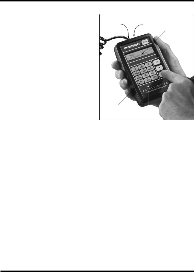
The IntelliScope Computerized Object Locator (controller) (Figure 21) will provide quick, easy access to thousands of celestial objects for viewing with your telescope.
The controller’s user-friendly keypad combined with its database of more than 14,000 celestial objects put the night sky literally at your fingertips.You just select an object to view, press Enter, then move the telescope manually following the guide arrows on the liquid crystal display (LCD) screen. In seconds, the IntelliScope’s high-resolution, 9,216-step digital encoders pinpoint the object, placing it smack-dab in the telescope’s field of view!
A. Alignment
This section will familiarize you with the alignment procedure for the IntelliScope system.
Powering the Controller
Install the included 9-volt alkaline battery in the battery compartment on the back of the controller. Make sure the positive and negative terminals are oriented as indicated by the labels next to the terminals in the battery compartment. To turn the controller on, firmly press the Power button. The LED lights will activate and the LCD screen will display its introduction message. The intensity of the illumination can be adjusted by repeatedly pressing the Power button. There are five levels of LED brightness. Choose a brightness level that suits your conditions and needs. (Dimmer settings will prolong battery life.)
To turn the controller off, press and hold the Power button for a few seconds, then release it.
To conserve battery life, the controller is programmed to shut itself off after being idle for 50 minutes. So, make sure to press a button at least once every 50 minutes if you do not want the controller to turn off. If the controller does turn off, you will need to perform the initial alignment procedure again.
If the LCD screen and the buttons’ backlighting automatically begin to dim, it’s time to change batteries.
Coil cable |
RS-232 |
Backlit |
|
jack |
jack |
||
liquid crystal |
|||
|
|
||
|
|
display |
Illuminated
pushbuttons User-friendly keypad
Figure 21. The IntelliScope Computerized Object Locator
Initial Vertical Alignment
After powering up the controller, the top line of the LCD display will read: “POINT VERTICAL.” If the top line reads “ALIGN DEC MARK,” simply press the up arrow button. The top line will now read “POINT VERTICAL”, and you are set to use the object locator with your IntelliScope Dobsonian.
If the vertical stop you installed on the top baseplate during assembly of the telescope is properly adjusted (see below), rotate the optical tube upward until the rear end ring comes in contact with the vertical stop knob, as shown in Figure 22. You may have to raise or lower the tube in the tube rings to achieve contact between the flat portion of the rear end ring and the vertical stop knob. Once the optical tube is in the vertical position, press the Enter button to start the two-star alignment procedure.
Setting the Vertical Stop
For the IntelliScope system to work accurately, the vertical stop must be precisely set so that the optical tube is truly perpendicular to the azimuth axis of the base when the controller says “POINT VERTICAL.” For this you will need a carpenter’s level, which you can find at just about any hardware store.
First, make sure the base itself is level. Place the carpenter’s level on the top baseplate and rotate the base 180˚ in azimuth (Figure 23). The level should indicate that the base is level through the entire rotation. If not, then reposition the base on the ground, or place shims underneath the feet until the base stays level though a 180˚ rotation.
Next, rotate the optical tube upward until the rear end ring comes in contact with the vertical stop knob. Place the carpenter’s level across the top of the optical tube (Figure 24). Is
16
Vertical stop
Rear end knob ring 
Jam nut
Vertical stop
L-bracket
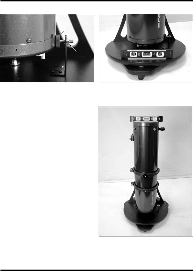
Figure 22. Once the vertical stop is adjusted and set initially, pointing the optical tube vertically is as easy as rotating the tube until the bottom end ring contacts the vertical stop knob, as shown. Make sure the middle of the end ring – not the rounded bottom edge – contacts the vertical stop knob.
it level? If so, thread the jam nut tight against the back of the L-bracket to secure the vertical stop knob in that exact position. If the top of the optical tube is not level, thread the vertical stop bolt in or out as needed until the top of the tube is level when the end ring comes in contact with the vertical stop knob. Then secure the vertical stop bolt in place with the jam nut.
Once the vertical stop bolt is accurately adjusted, it should not need adjustment again. The base does not need to be level for the IntelliScope system to function properly; the base only needs leveling when initially setting the vertical stop.
Simple Two-Star Alignment
After setting the vertical position of the optical tube, a simple two-star alignment process is all that is needed to ready the IntelliScope system for operation. This is a great simplification from many other computerized systems, which require you to enter data such as your longitude, latitude, and time zone. For the IntelliScope controller to accurately find objects, you only need to center two bright stars in your telescope and indicate to the controller which two stars you have centered. This is quite easy to do. For your convenience, we have provided finder charts for the alignment stars in Appendix D. Use the finder chart to locate and identify two bright stars in your current night sky. For best results, choose two stars that are at least 60˚ apart from each other. (The width of your fist at arm’s length is about 10˚, so you want the stars to be at least six fistwidths apart.)
So, the optical tube is now in the vertical position and you’ve chosen two bright stars in the sky to use for alignment. The telescope should have a high-power eyepiece, such as the 10mm Sirius Plössl, in the eyepiece holder and the finder scope should be properly aligned with the telescope (these procedures are described elsewhere in this manual). The LCD screen will state on its top line “ALIGN STAR 1,” with the name of a star flashing on the second line.
Figure 23. Place a carpenter’s level on the altazimuth base as shown. Add shims under the three feet as needed so that the base stays level through a 180-degree rotation in azimuth. Once the vertical stop is set, the base does not need to be level to function properly.
Figure 24. Once the base is leveled, point the optical tube up until the mirror cell (bottom end ring) contacts the vertical stop knob. Then place the carpenter’s level across the top of the tube as shown and adjust the vertical stop knob until the tube is level. After each adjustment of the vertical stop knob, make sure to re-establish contact between the telescope end ring and the knob before checking the carpenter’s level.
17

Use the arrow buttons to scroll through the names of the alignment stars. The up arrow button scrolls through the stars alphabetically from A to Z. The down arrow button scrolls alphabetically backwards, from Z to A. When you arrive at the name of the star you wish to align on, you can begin to move the telescope so that it is pointing at that star (but don’t press the Enter button yet).
Note: The controller will not accept Polaris as the first alignment star. This helps prevent the pointing accuracy from decreasing over time. It is OK to use Polaris as the second alignment star, however.
Take hold of the “navigation knob” on the optical tube and move the telescope so that it is pointing in the general area of the alignment star. Aim the telescope so the alignment star appears in finder scope. Be careful not to confuse the alignment star with other stars in the area when doing this. (It will likely be the brightest star in the field of view.) Now, move the telescope until you have centered the star on the crosshairs of the finder scope. Look into the eyepiece of the telescope, and you should see the alignment star in the field of view of the eyepiece. If it isn’t, then your finder scope is out of alignment with your telescope and will need to be adjusted. Once the alignment star is in the eyepiece’s field of view, center it in the eyepiece as best you can by making small movements to the telescope. (If you have one, an illuminated reticle eyepiece is great for centering alignment stars). Once this is done, press the Enter button on the controller. You have now completed one-half of the two-star alignment.
The LCD screen will now read “ALIGN STAR 2” on the first line with an alignment star’s name flashing on the second line. As before, scroll through the names of the stars with the arrow buttons until you reach your second chosen alignment star. Repeat the procedure described above for your second alignment star. When you have aligned on the second star, press the Enter button. The LCD will then display a number. It is the alignment error factor, or “warp” (W) factor.
The Alignment Error (Warp) Factor
The “warp” alignment error factor essentially lets you know if your alignment was accurate or not. Ideally, this number should be as low as possible, but any “W” of 0.5 or smaller is acceptable (regardless of + or - sign). Warp factors of ±0.3 and ±0.4 are the most common. Warp factors under ±0.2 are typically not achievable (but kudos to you if you get one!). If you complete an alignment and the warp factor is larger than ±0.5 (e.g., +0.6, -0.6, +0.7, -0.7, etc.), then you must turn the controller off (by holding down the Power button) and begin the alignment procedure again. Otherwise, there is no guarantee that the controller will consistently place objects within the field of view of a medium-low power eyepiece.
An unacceptable warp factor may indicate that you aligned on the wrong star or did not have the telescope initially in a precisely vertical position. If you are having problems getting the warp factor at or below ±0.5, see the troubleshooting section in Appendix C.
Your IntelliScope Computerized Object Locator is now ready to find objects. Replace the high-powered eyepiece you used
Figure 25. If you’re positioned to the left of the telescope and face the direction the optical tube is pointed, the guide arrows on the Computerized Object Locator will correspond exactly with the direction you should move the telescope to pinpoint the selected object.
for centering the alignment stars with a low-power, wide-field eyepiece, such as the 25mm Sirius Plössl.
B. Overview of the IntelliScope Computerized Object Locator
The IntelliScope Computerized Object Locator (controller) has been specifically designed for ease of use. This section will help familiarize you with the basic layout and operation of the controller.
Pushbuttons
Besides the Power, Enter, ID, FCN, and up/down arrows, all pushbuttons have letters on them with numbers above them (Figure 21). The letters designate the function of the pushbutton. The numbers above them are used for entering numerical data only; the numbers are never active until a function is first chosen. The numbers are arranged like a telephone keypad for ease of number entry. None of the function buttons will work properly until an initial alignment, as outlined previously, is completed. If you press a function button be-fore the twostar alignment is completed, the controller will display “MUST STAR ALIGN.” Turn the unit off, then on again (by using the Power button), to begin the alignment routine again.
18

a.
b.
c.
The Guide Arrows
Figure 26. This sequence of pictures illustrate how the
Computerized Object Locator’s guide arrows look as you are finding a celestial object. (a) When the optical tube is aimed far away from the object’s location, there will be a number (from 10 to 179) to the left of the guide arrows. (b) When the scope is aimed close to the object, each guide arrow will display a number on its immediate left (from 0 to 9) and immediate right (from 0
to 9); the number on the left is whole number increments, while the number on the right is in increments of tenths. This helps in making small movements to the telescope to pinpoint the object’s location. (c) When the guide arrows display “0.0 0.0”, the object will be within the field of view of the telescope (with a 25mm or longer focal length eyepiece).
The controller leads you to astronomical targets with guide arrows displayed on the LCD screen. After an object is selected to view, you will see two guide arrows, one that points left or right, and one that points up or down. Move the telescope tube in the corresponding direction of the guide arrows. If you are standing to the left of the telescope and facing the same direction the telescope is pointed, the guide arrows will exactly correspond with the direction you should move the telescope (Figure 25). Otherwise, if an up arrow is displayed, move the telescope tube upward, if a down arrow is displayed, move the telescope tube downward, if a left arrow is displayed, rotate the telescope counterclockwise, and if a right arrow is displayed, rotate the telescope clockwise. There is a number next to each guide arrow that indicates how far the telescope needs to be moved to reach the selected object. As you move the telescope toward the object, this number will decrease. When the number goes below ten, the figure will be displayed in tenths; this helps to make small, precise movements to the telescope tube in order to bring the object into your field of view. When both numbers reach zero, stop moving the telescope. The object will be within the field of view of a mediumto low-power eyepiece (25mm focal length or longer).
For example, look at Figure 26a, which shows the LCD screen for someone trying to locate M51, otherwise known as the Whirlpool Galaxy. The first arrow is pointing right and gives a number of 34. The second arrow is pointing up and displays the number 12. This means that the telescope tube should be moved to the right (clockwise) and up. When you are close to
M51, the numbers will be displayed in tenths, as is shown in Figure 26b. When the numbers reach zero (Figure 26c), the telescope will be pointed right at the Whirlpool Galaxy.
It is easiest to move the telescope in one direction at a time (say altitude) until the corresponding number reached “0.0”. Then move the scope in the other direction (azimuth) until that number also reads “0.0”.
If the object selected to view is currently located below the horizon, the word “HORIZON” will flash before the guide arrows are displayed. Choose another object to view.
C. Locating the Planets
By far the most popular objects for viewing, after the Moon, are the planets. Since the other eight planets in our solar system are also orbiting the Sun, they do not appear in fixed positions in the night sky like deep-sky objects and stars do. Because of this, the controller requires you to input the date before it can find the planets.
To find planets with your IntelliScope Computerized Object Locator, use the following procedure:
1.Press the Planet button on the controller.
2.The LCD screen will display a date similar to the following:
3.The number after the word “DATE” will be flashing and represents the day of the month. Input the two-digit day using the number buttons.
4.The three-letter month will now be flashing. Use the arrow buttons to scroll to the present month and then press the Enter button.
5.Now the year will flash. Input the year using the number buttons.
If you make a mistake while inputting the date, press the Enter button at any time while still within the Planet button function. The LCD screen will then display the last date input, with the two-digit day after the word “DATE” flashing. Input the correct date as outlined above.
Now, to choose a planet to view, press the arrow buttons and scroll through the planets. The planet’s name will be displayed in the upper left section of the LCD screen, with the guide arrows on the upper right of the LCD screen. Move the telescope in the corresponding direction shown by the guide arrows.
The lower left screen shows the constellation that the planet appears in, with its present co-ordinates given in right ascension and declination. When you are finished viewing the planet, you may scroll to another planet by using the arrow buttons.
The features and details you can see will vary from planet to planet. The following descriptions give a brief overview of what to expect when viewing them:
MERCURY Mercury is often so close to the Sun that it cannot be seen. Sometimes it is visible for a brief period after the Sun sets, and sometimes it’s visible in the morning just before the Sun rises. Mercury does not really show any detail, but is quite bright. With your telescope, you will be able to investigate this
19
 Loading...