


instruction Manual
Orion® Atlas™ EQ-G
Equatorial Mount
#9996
|
|
|
|
|
Customer Support (800) 676-1343 |
|
|
|
|
|
|
|
|
|
|
|
E-mail: support@telescope.com |
|
|
|
|
|
|
|
|
|
|
|
|
|
|
|
|
|
Corporate Offices (831) 763-7000 |
|
|
|
|
|
|
Providing Exceptional Consumer Optical Products Since 1975 |
89 Hangar Way, Watsonville, CA 95076 |
||||
IN 279 Rev. C 01/09

Tube ring mounting plate
Mounting plate lock knobs
Declination lock lever
Declination setting circle 
Front opening 
Counterweight shaft lock lever
Counterweight shaft
Counterweights 
Counterweight lock knobs 
“Toe-saver”
GoTo hand controller cable
Tripod leg
Leg lock levers
Figure 1. The Atlas EQ-G mount.
Power switch
Power indicator light 12V DC power jack Auto guider jack
Right Ascension
setting circle
Right Ascension
lock lever
Hand controller jack
Latitude scale
Latitude adjustment L-bolts
Center support shaft
Tripod center support tray
GoTo hand controller
2

Congratulations on your purchase of a quality Orion mount. Your new Atlas EQ-G mount works with many different optical tubes. Designed for astronomical use, the Atlas EQ-G provides a solid, stable foundation for precise navigation of the night sky. The internally housed, dual-axis stepper motors provide smooth slewing and tracking of any celestial object. With a little practice, you’ll find that the Atlas EQ-G mount is an invaluable tool for getting the most out of your astronomical observing sessions.
These instructions will help you set up and properly use your equatorial mount. Please read them over thoroughly before getting started.
Table of Contents
1. |
Unpacking . . . . . . . . . . . . . |
. 3 |
2. |
Parts List . . . . . . . . . . . . . . |
3 |
3. |
Assembly . . . . . . . . . . . . . . |
3 |
4. |
Attaching a Telescope . . . . . . . . . |
4 |
5. |
Balancing a Telescope . . . . . . . . . |
4 |
6.Setting Up and Using the Equatorial Mount . . 5
7.The Atlas EQ-G Dual Axis Hand Controller . 8
8.The Atlas EQ-G GoTo Hand Controller . . 10
9.Specifications . . . . . . . . . . . . 19
10.Appendices . . . . . . . . . . . . 21
1. Unpacking
The entire mount will arrive in three boxes, one containing the tripod, one containing the equatorial mount, and one containing the hand controller. Be careful unpacking the boxes. We recommend keeping the boxes and original packaging. In the event that the mount needs to be shipped to another location, or returned to Orion for warranty repair, having the proper packaging will ensure that your mount will survive the journey intact.
Make sure all the parts in the Parts List are present. Be sure to check the box carefully, as some parts are small. If anything appears to be missing or broken, immediately call Orion Customer Support (800-676-1343) or email support@telescope.com for assistance.
Box 3: Dual-Axis Hand Controller
1Dual-Axis hand controller
2Nylon hook-and-loop strips (1 hook strip, 1 loop strip)
1 Wire clip
If you’ve purchased the #7947 GoTo hand controller:
Box 3: GoTo Hand Controller
1 GoTo hand controller
1 GoTo hand controller cable for Sirius EQ-G 1 GoTo hand controller cable for Atlas EQ-G 1 GoTo hand controller bracket
1 Computer interface cable (RS-232)
1Wire clip
3.Assembly
Refer to Figure 1 as needed during the assembly process.
1.Stand the tripod legs upright and spread the legs out as far as they will go. Make certain that the leg lock levers are tightened. Keep the tripod legs at their shortest (fully retracted) length, for now; you can extend them to a more desirable length later, after the mount is fully assembled.
2.Place the base of the equatorial mount onto the tripod head. Orient the equatorial mount so that the post on the tripod head lines up with the azimuth adjustment knobs on the equatorial mount (Figure 2). You may need to loosen the azimuth adjustment knobs on the equatorial mount in order to fit the mount onto the tripod head.
2. Parts List
Box 1: Tripod
Qty. Item
1Tripod
2Counterweights (11lbs. each)
1Tripod center support tray
Box 2: Equatorial Mount
1 Equatorial mount
1 Tube ring mounting plate
1 12V DC Power cable
If you’ve purchased the #7945 Dual-Axis hand controller:
Azimuth adjustment knobs
Post
Figure 2. Orient the equatorial head so that the post on the tripod lines up with the azimuth adjustment knobs on the equatorial mount.
3
3.Thread the center support shaft up through the tripod head and into the bottom of the equatorial mount until tight. Use the upper knob on the center support shaft to do this. The equatorial mount should now be firmly connected to the tripod.
4.Remove the knob and washer from the bottom of the center support shaft. Slide the tripod support tray up the bottom of the central support shaft until the three tray arms are touching the legs of the tripod. The flat side of the support tray should be facing up. Make sure the “V” of each tray arm is against a tripod leg. Place the washer on the center support shaft against the tray, and follow it by threading the knob all the way up the center support shaft until it is tight against the tray. The tripod support tray provides additional stability for the tripod, and holds up to five 1.25" eyepieces and two 2" eyepieces.
5.Loosen the counterweight shaft lock lever and fully extend the counterweight shaft. Retighten the lock lever.
6.Remove the knurled “toe saver” retaining screw on the bottom of the counterweight shaft and slide both counterweights onto the shaft. Make sure the counterweight lock knobs are adequately loosened to allow the counterweight shaft to pass through the hole. Position the counterweights about halfway up the shaft and tighten the lock knobs. Replace the toe saver at the end of the bar. The toe saver prevents the counterweights from falling on your foot if the lock knobs happen to come loose.
Your Atlas EQ-G mount is now fully assembled and should resemble Figure 1 except for the hand controller, which will be installed and explained in Section 7 (Dual-Axis) or Section 8 (GoTo) of this manual.
4. Attaching a Telescope
The Atlas EQ-G equatorial mount is designed to hold telescope tubes weighing up to approximately 40 lbs. For heavier telescopes, the mount may not provide sufficient stability for steady imaging. Any type of telescope can be mounted on the Atlas EQ-G, including refractors, Newtonian reflectors, and catadiotropics, provided a set of tube rings is available to couple the tube to the mount. Orion sells a variety of telescope tube rings. Please visit our website at OrionTelescopes.com for details.
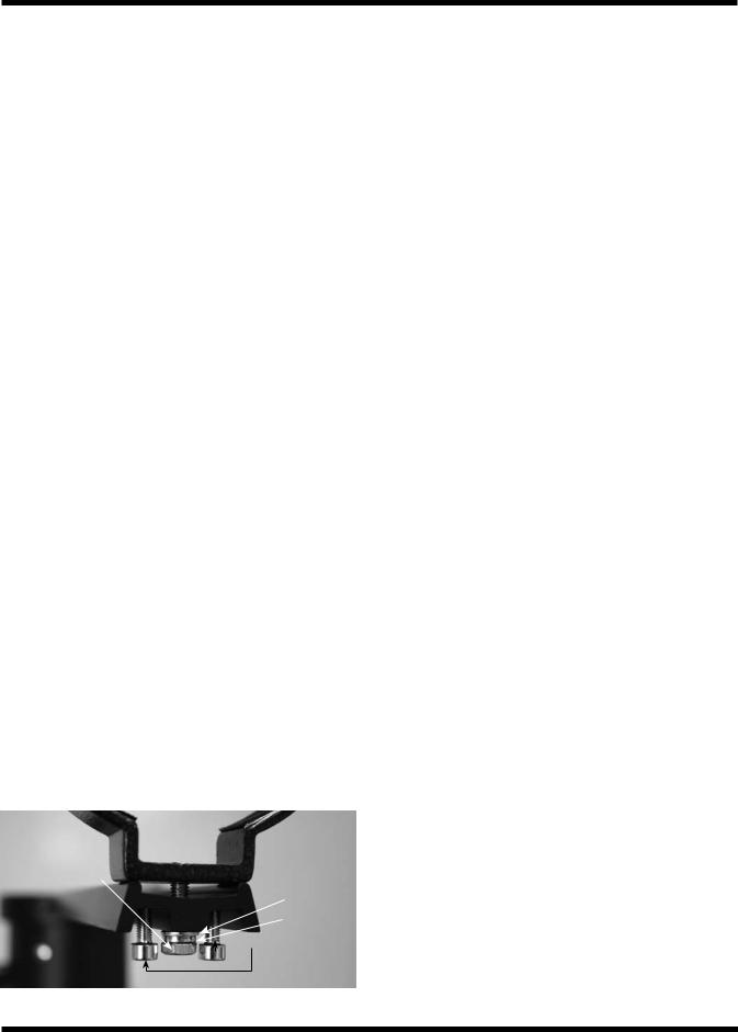
1.Attach the tube mounting rings to the tube ring mounting plate using the screws that come with the tube rings. The screws should go through the center holes in the ends of the mounting plate and rethread into the tube rings. Note that the side of the mounting plate with the central “groove” will be facing up (Figure 3). Use a small wrench to secure the tube rings to the mounting plate.
Note: The tube ring mounting plate included with the Atlas EQ G includes four optical axis offset adjustment screws; these are the socket head cap screws located at each corner of the mounting plate. These adjustment screws will be explained further in Appendix A. For now, confirm that all four adjustment screws are sufficiently unthreaded so that the ends of their threaded shafts are flush with the top surface of the tube ring mounting plate.
Note: The optical axis offset adjustment screws should be oriented so that the threaded shaft extends upward through the top surface of the tube ring mounting plate. If the tube ring mounting plate arrives with the optical axis offset screws installed backwards, reverse their orientation before proceeding (Figure 3).
2.Loosen the black mounting plate lock knobs on the top of the equatorial mount. Place the mounting plate, with the tube rings attached, in the slot on top of the equatorial mount. Position the mounting plate so that it is centered in the slot. Re-tighten the mounting plate lock knobs until the plate is secure.
3.Open the tube rings and lay the telescope optical tube in the rings at about the midpoint of the tube’s length. Rotate the tube so that the focuser is at a convenient height for viewing. Close the tube rings and tighten them.
Note: The Atlas EQ-G mount is very heavy. Alone it weighs 54 lbs. With a large optical tube and counterweights it can easily weigh over 100 lbs. Keep this in mind when moving the telescope even small distances, and use assistance when needed. It is best to remove the optical tube and counterweights when moving the mount.
Note: Some telescope optical tubes (specifically SchmidtCassegrains and Maksutov-Cassegrains) have a mounting plate connected directly to the tube. For these telescopes, optional tube rings are not required. Simply follow step 2 (above) to connect the telescope to the mount.
Tube ring attachment screw
Flat washer
Lock washer
Optical axis offset adjustment screws
Figure 3. The tube ring mounting plate.
5. Balancing a Telescope
To ensure smooth movement of a telescope on both axes of the equatorial mount, it is imperative that the optical tube is properly balanced. We will first balance the telescope with respect to the right ascension (R.A.) axis, then the declination (Dec.) axis.
1.Keeping one hand on the telescope optical tube, loosen the R.A. lock lever. Make sure the Dec. lock lever is locked, for now. The telescope should now be able to rotate freely about the right ascension axis. Rotate it until the counterweight shaft is parallel to the ground (i.e., horizontal).
4
2.Now loosen both counterweight lock knobs and slide the weights along the shaft until they exactly counterbalance the telescope (Figure 4a). That’s the point at which the shaft remains horizontal even when you let go with both hands (Figure 4b). If the telescope refuses to balance than you have either too much or too little counterweight. Remove a counterweight, or add optional counterweights if needed.
3.Retighten the counterweight lock knobs. The telescope is now balanced on the right ascension axis.
4.To balance the telescope on the declination axis, first tighten the R.A. lock lever, with the counterweight shaft still in the horizontal position.
5.With one hand on the telescope optical tube, loosen the Dec. lock lever. The telescope should now be able to rotate freely about the declination axis.
6.Loosen the knurled ring clamps on the tube rings a few turns, until you can slide the telescope tube forward and back inside the rings (this can be aided by using a slight twisting motion on the optical tube while you push or pull on it) (Figure 4c).
7.Position the telescope in the tube rings so it remains horizontal when you carefully let go with both hands. This is the balance point for the optical tube with respect to the Dec. axis (Figure 4d).
8.Retighten the knurled ring clamps.
a. b.
c. d.
Figure 4a-d. Proper operation of the equatorial mount requires that the telescope tube be balanced on the R.A. and Dec. axes. (a) With the R.A. lock lever released, slide the counterweights down the counterweight shaft until they just counterbalance the telescope tube. (b) When you let go with both hands, the tube should not drift up or down. (c) With the Dec. lock lever released, loosen the tube ring lock clamps a few turns and slide the telescope forward or back in the tube rings. (d) When the tube is balanced about the Dec. axis, it will not move when you let go.
The telescope is now balanced on both axes. When you loosen the lock lever on one or both axes and manually point the telescope, it should move without resistance and should not drift from where you point it.
6. Setting Up and Using the
Equatorial Mount
Dec. lock lever  (not shown)
Front opening |
|
(RRight |
|
|
|
|
|
Ascension |
|
|
|
|
. |
|
|
|
|
A |
|
|
|
|
. |
|
|
|
|
) |
|
|
|
|
axis |
|
|
(Dec) |
axis |
|
|
Declination |
|
|
||
|
adjustment |
|
||
|
|
|
Azimuth |
|
|
|
|
knobs (2) |
|
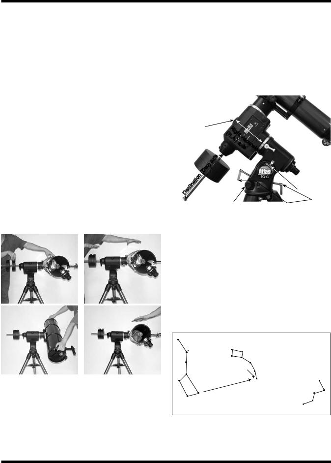
Figure 5. The Atlas EQ-G mount.

 R.A. lock lever
 Polar axis finder scope
Latitude scale
Latitude adjustment L-bolts
When you look at the night sky, you no doubt have noticed that the stars appear to move slowly from east to west over time. That apparent motion is caused by the Earth’s rotation (from west to east). An equatorial mount (Figure 5) is designed to compensate for that motion, allowing you to easily “track” the movement of astronomical objects, thereby keeping them from drifting out of your telescope’s field of view while you’re observing.
This is accomplished by slowly rotating the telescope on its right ascension (R.A.) axis, using the built in motor drive. But first the R.A. axis of the mount must be aligned with the Earth’s rotational (polar) axis—a process called polar alignment.
Little Dipper
(in Ursa Minor)
Big Dipper |
N.C.P. |
|
|
(in Ursa Major) |
|
Polaris
Pointer |
Cassiopeia |
|
Stars |
||
|
Figure 6. To find Polaris in the night sky, look north and find the Big Dipper. Extend an imaginary line from the two “Pointer Stars” in the bowl of the Big Dipper. Go about five times the distance between those stars and you'll reach Polaris, which lies within 1° of the north celestial pole (NCP).
5
Polar Alignment
For Northern Hemisphere observers, approximate polar alignment is achieved by pointing the mount’s right ascension axis at the North Star, or Polaris. It lies within 1° of the north celestial pole (NCP), which is an extension of the Earth’s rotational axis out into space. Stars in the Northern Hemisphere appear to revolve around the NCP.
To find Polaris in the sky, look north and locate the pattern of the Big Dipper (Figure 6). The two stars at the end of the “bowl” of the Big Dipper point right to Polaris.
Observers in the Southern Hemisphere aren’t so fortunate to have a bright star so near the south celestial pole (SCP). The star Sigma Octantis lies about 1° from the SCP, but it is barely visible with the naked eye (magnitude 5.5).
For general visual observation, an approximate polar alignment is sufficient.
1.Level the equatorial mount by adjusting the length of the three tripod legs.
2.There are two latitude adjustment L-bolts (see Figure 5); loosen one while tightening the other. By doing this you will adjust the latitude of the mount. Continue adjusting the mount until the pointer on the latitude scale is set at the latitude of your observing site. If you don’t know your latitude, consult a geographical atlas to find it. For example, if your latitude is 35° North, set the pointer to 35. The latitude setting should not have to be adjusted again unless you move to a different viewing location some distance away.
3.Loosen the Dec. lock lever and rotate the telescope’s optical tube until it is parallel with the right ascension axis, as it is in Figure 5.
4.Move the tripod so the telescope tube and right ascension axis point roughly at Polaris. If you cannot see Polaris directly from your observing site, consult a compass and rotate the tripod so the telescope points north.
The equatorial mount is now polar aligned for casual observing. More precise polar alignment is recommended for astrophotography. For this we recommend using the polar axis finder scope.
From this point on in your observing session, you should not make any further adjustments to the latitude of the mount, nor should you move the tripod. Doing so will undo the polar alignment. The telescope should be moved only about its R.A. and Dec. axes.
The Polar Axis Finder Scope
The Atlas EQ-G mount comes with a polar axis finder scope (Figure 7) housed inside the right ascension axis of the mount. When properly aligned and used, it makes accurate polar alignment quick and easy to do. Unthread the cover at the rear of the mount’s right ascension axis and remove the cap on the front opening of the equatorial mount (Figure 5) to view through the polar axis finder scope.
Alignment of the Polar Axis Finder Scope
1.Loosen the Dec. lock lever and rotate the optical tube about the declination axis until you have a clear view through the polar axis finder scope (Figure 8). Tighten the Dec. lock lever.
2.Look through the polar finder at a distant object (during the day) and center it in the crosshairs. You may need to adjust the latitude adjustment L-bolts and the tripod position to do this. Focus the polar finder by rotating the eyepiece.
3.Rotate the mount 180° about the R.A. axis. It may be convenient to remove the counterweights and optical tube before doing this.
4.Look through the polar finder again. Is the object being viewed still centered on the crosshairs? If it is, then no further adjustment is necessary. If not, then look through the polar finder while rotating the mount about the R.A. axis. You will notice that the object you have previously centered moves in a circular path. Use the three alignment set-screws on the polar axis finder (Figure 7) to redirect the crosshairs of the polar finder to the apparent center of this circular path.
5.Repeat this procedure until the position that the crosshairs point to does not rotate off-center when the mount is rotated in R.A.
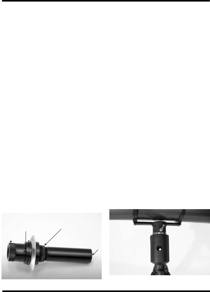
Eyepiece |
Alignment |
Focus |
Objective |
|||
focus ring |
setscrew (3) |
lock ring |
lens |
|
|
|
|
||||||
|
|
|
|
|
|
|
|
|
|
|
|
|
|
Figure 7. The polar axis finder scope. |
Figure 8. The optical tube must be rotated about the declination |
axis in order to view through the polar axis finder. |
6
The polar axis finder scope is now ready to be used. When not in use, replace the plastic protective cover to prevent the polar finder from getting bumped.
Using the Polar Axis Finder Scope
The reticle of the polar axis finder scope for the Atlas EQ G has a tiny star map printed on it that makes precise polar alignment quick and easy. To polar align the mount using the polar axis finder scope, follow these instructions:
1.Approximately polar-align the mount as outlined in the procedure above.
2.Loosen the Dec. lock lever and rotate the optical tube on the declination axis so the tube is at a 90° angle to the right ascension axis (Figure 8). Tighten the Dec. lock lever.
3.Focus the polar finder by rotating the eyepiece. Now, sight Polaris in the polar axis finder scope. If you have followed the approximate polar alignment procedure accurately, Polaris will probably be within the field of view. If not, move the tripod left-to-right, and adjust the latitude up-and down until Polaris is somewhere within the field of view of the polar axis finder scope.
4.The mount has a built-in illuminator that allows you to see the reticle pattern in the polar axis finder scope at night. Simply turn on the power switch on the Atlas EQ-G mount (see “Powering the Atlas EQ-G Mount”) and the polar axis finder scope reticle will be illuminated. Note the constellation Cassiopeia and the Big Dipper in the reticle. They do not appear in scale, but they indicate the general positions of Cassiopeia and the Big Dipper relative to the north celestial pole (which is indicated by the cross at the center of the reticle). Rotate the reticle so the constellations depicted match their current orientation in the sky when viewed with the naked eye. To do this, release the R.A. lock lever and rotate the main telescope around the R.A. axis until the reticle is oriented with sky. For larger optical tubes, you may need to remove the tube from the mount to prevent it from bumping into the mount. Once the reticle is correctly oriented, use the right ascension lock lever to secure the mount’s position.
5.Now use the azimuth adjustment knobs (Figure 2) and the latitude adjustment L-bolts (Figure 5) on the mount to position the star Polaris inside the tiny circle marked “Polaris” on the finder’s reticle.You must first loosen the knob underneath the equatorial mount on the center support shaft to use the azimuth adjustment knobs. Once Polaris is properly
positioned within the reticle, you are precisely polar aligned. Retighten the knob underneath the equatorial mount.
If you do not have a clear view of Polaris from your observing site, you will not be able to use the polar-axis finder to precisely polar align the telescope.
Note: From this point on in your observing session, you should not make any further adjustments in the azimuth or the latitude of the mount, nor should you move the tripod. Doing so will undo the polar alignment. The telescope should be moved only about its right ascension and declination axes.
Additional Note Regarding Focusing the Polar Axis Finder Scope
The polar axis finder scope is normally focused by simple rotation of the eyepiece focus ring. However, if after adjusting the focus ring you find that the image of the reticle is sharp, but the stars are out of focus, then you must adjust the focus of the polar axis finder’s objective lens. To do this, first remove the polar axis finder from the mount by unthreading it. Look through the polar axis finder at a star (at night) or distant object at least 1/4 mile away (during daylight). Use the eyepiece focus ring to bring the reticle into sharp focus. Now, loosen the focus lock ring (Figure 7) and thread the entire objective end of the finder inward or outward until images appear sharp. Re-tighten the focus lock ring. Once the polar axis finder’s objective lens is focused, it should not need to be adjusted again.
Confused About Pointing the Telescope?
Beginners occasionally experience some confusion about how to point the telescope overhead or in other directions. In Figure 1 the telescope is pointed north as it would be during polar alignment. The counterweight shaft is oriented downward. But it will not look like that when the telescope is pointed in other directions. Let’s say you want to view an object that is directly overhead, at the zenith. How do you do it?
DO NOT make any adjustment to the latitude adjustment L- bolts. That will spoil the mount’s polar alignment. Remember, once the mount is polar aligned, the telescope should be moved only on the R.A. and Dec. axes. To point the scope overhead, first loosen the R.A. lock lever and rotate the telescope on the right ascension axis until the counterweight shaft is horizontal (parallel to the ground). Then loosen the Dec. lock lever and rotate the telescope until it is pointing straight overhead. The counterweight shaft is still horizontal. Then retighten both lock levers.
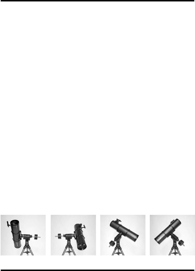
a. |
b. |
c. |
d. |
Figure 9a-d. These illustrations show the telescope pointed in the four cardinal directions. (a) north, (b) south, (c) east, (d) west. Note that the tripod and mount have not been moved; only the telescope has been moved on the its R.A. and Dec. axes.
7

What if you need to aim the telescope directly north, but at an object that is nearer to the horizon than Polaris? You can’t do it with the counterweights down as pictured in Figure 1. Again, you have to rotate the scope in right ascension so that the counterweight shaft is positioned horizontally. Then rotate the scope in declination so it points to where you want it near the horizon.
To point the telescope directly south, the counterweight shaft should again be horizontal. Then you simply rotate the scope on the declination axis until it points in the south direction.
To point the telescope to the east or west, or in other directions, you rotate the telescope on its right ascension and declination axes. Depending on the altitude of the object you want to observe, the counterweight shaft will be oriented somewhere between vertical and horizontal.
Figure 9 illustrates how the telescope will look when pointed at the four cardinal directions: north (Figure 9a), south (Figure 9b), east (Figure 9c) and west (Figure 9d).
The key things to remember when pointing the telescope are that a) you only move it in right ascension and declination, not in azimuth or latitude (altitude), and b) the counterweight and shaft will not always appear as it does in Figure 1. In fact it almost never will!
7. The Atlas EQ-G Dual-Axis
Controller
The Atlas EQ-G with dual-axis hand controller will track any celestial object as the Earth rotates. You can also use the controller’s directional buttons to center objects within your telescope’s finderscope or eyepiece. For imaging purposes, the controller provides several guide speed rates so a camera can be accurately guided during a long exposure.
Attaching the Dual-Axis Controller
The dual-axis controller has a cable with a large, serial connector (DB-9) on one end. Plug the serial connector into the jack on the faceplate of the mount (Figure 9.1). Use the captive screws to secure the serial connector in place.
The nylon hook-and-loop strips have been provided so the dual-axis hand controller can be placed in a convenient position on the mount when not in use. Place the “hooks” strip on the back of the dual-axis hand controller, and the “loops” strip on the mount in a convenient location. Make certain the location of the strip on the mount will not cause the dual-axis hand controller to interfere with the motions of the mount or telescope being used.
You can reduce the chances of getting your hand controller, power supply, or other cables tangled during use of the Atlas EQ-G by using the included wire clip. The clip also prevents mechanical strain on the cord when being used. The wireclip is adhesive backed for easy attachment to any convenient location on the mount.
Powering the Atlas EQ-G Mount
The Atlas EQ-G should be powered by a 12V DC power supply (tip-positive) capable of producing continuous current with a minimum of 2 amps. We recommend using a portable rechargeable battery, like the Dynamo or Dynamo Pro available from Orion.
If you are using a portable battery like the Orion Dynamo, use the supplied 12V DC power cable (male cigarette lighter plug on one end, standard 12V DC power plug on the other end) to connect the battery to the 12V DC power jack on the faceplate of the mount (Figure 9.1). Make sure the Dynamo’s power switch is in the “on” position after connecting.
Functions of the Dual-Axis Hand Controller
There are three main categories of control buttons on the dualaxis controller (Figure 9.2).
1.Speed buttons
2.Directional buttons
3.Set button
The dual-axis hand controller is equipped with a red LED light in each button to indicate operation. An individual button’s LED will illuminate when the button is pressed. If a button combination is entered, all LEDs will illuminate to indicate a successful operation.
Speed Buttons
The three buttons located near the top of the dual-axis hand controller (Guide, Slow, and Fast) are used to set the slewing and guiding speed of the mount.
Directional Buttons
The directional buttons allow complete control of the mounted telescope’s position during slewing or tracking. The Left and Right directional buttons control movements about the right ascension (R.A.). axis. The Up and Down directional buttons control movements about the declination (Dec.) axis.
Set Button
The Set button is used to set the dual-axis hand controller to operate in either Northern or Southern hemisphere locations.
Note: The Go button is not used in normal operation of the dual-axis controller.
Tracking Objects with the Dual-Axis Hand Controller
In order for your Atlas EQ-G mount to accurately track celestial objects as they appear to migrate across the night sky, your mount must be properly polar aligned. For more details on polar alignment, please consult section 6 of this manual.
Once the power switch is turned on, the dual-axis controller begins to track by rotating the R.A. axis motor at the default (sidereal) rate. The Dec. axis motor will not rotate. As long as the mount has been properly polar aligned, it should not be necessary to adjust the Dec. axis for accurate tracking. If you notice a lack of tracking precision at the default (sidereal) rate,
8
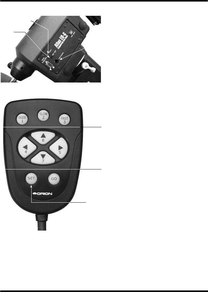
Power indicator light
12V DC
power jack 
 Power switch
Autoguider modular jack
 Hand controller serial jack
Figure 9-1. Atlas EQ-G mount faceplate.
Speed

 buttons
Directional

 buttons
Set button
Figure 9-2. The Atlas EQ-G Dual-Axis hand controller
consult section 6 of this manual and attempt to polar align the mount more accurately.
Tracking can be deactivated or activated at any time the Atlas EQ-G mount is receiving power. In order to deactivate tracking, simply press and hold the Guide button then press the Slow button on the controller. Pressing the same button combination will reactivate tracking at the default (sidereal) rate.
There are three tracking rates used by the dual-axis controller:
Sidereal rate tracking is the default tracking rate for the Atlas EQ-G mount. Celestial objects are tracked using this rate which is equivalent to the rate of the Earth’s rotation.
Solar rate tracking is used to track the Sun over a long period of time. Solar rate tracking is activated by pressing and holding the Slow speed button, then the Right directional button.
Warning: Never look directly at the Sun through your telescope or its finder scope, even for an instant, without a professionally made solar filter that completely covers the front aperture of the instrument, or permanent eye damage could result.Young children should use this telescope only with adult supervision.
Lunar rate tracking is used to track the Moon at its rate of apparent motion across the sky. Lunar rate tracking is activated by pressing and holding the Slow button, then the Down directional button.
Note: Solar and Lunar tracking rates can only be used when the Atlas EQ-G has tracking activated. If tracking is deacti vated, you must first activate tracking by holding the Guide button then pressing the Slow button.
Setting the Slewing Speed
In order to conveniently center an object in your telescope’s finderscope or eyepiece, you can set the speed rate at which the motors slew (move) the telescope when the directional buttons are pressed. The three speed buttons located near the top of the hand controller are used to set the slewing rates of the mount.
The slewing speed buttons each have two different speeds assigned to them. The slewing speed employed is dependent on whether or not the dual-axis controller has tracking activated or deactivated (by holding the Guide button then pressing the Slow button).
With tracking activated, the Guide button will slew the Atlas EQ-G mount at a very slow speed equal to 1.5x sidereal rate. This speed rate will generally be used to guide a telescope while imaging with a camera. You can also change the Guide button speed rate to be slightly faster or slower (see “Setting the Guiding Speed”). If tracking is deactivated, pressing the Guide button will set the Atlas EQ-G to slew at 32x sidereal rate; this speed is too fast for guiding during imaging.
By pressing the Slow button with tracking activated, the Atlas EQ-G will slew at 4x sidereal rate. With tracking deactivated, pressing the Slow button will set the Atlas EQ-G mount to slew at 64x sidereal rate.
With tracking activated, the Fast button will set the Atlas EQ-G mount to slew at 8x sidereal rate. If tracking is not activated, pressing the Fast button will set the Atlas EQ-G to slew at 800x sidereal rate; this is a very fast speed that can be used to slew the mount from object to object across the sky.
9
 Loading...