


www.orioncontrols.com |
PT-Link II BACnet2® |
Technical Guide |
RNE Controller Code: SS1045 |
VCB-X Controller Code: SS1051 Version 2.0 |
VCM-X Controller Code: SS1026 & Y200920 Version 2.0 and up; |
VCM-X Modular Controller Code: SS1030 & SS1034 |
VCM-X WSHP Controller Code: SS1032 & SS1033 |
SA Controller Code: Y200921 |
VCM Controller Code: SS1016, Y200409, Y200616, Y200822 |
www.orioncontrols.com
OE368-23B-BACNET2
PT-LINK II PROTOCOL
TRANSLATOR
FOR BACNET
LED BLINK CODES (NORMAL)
LOOP |
= |
RAPID BLINK |
PROTO |
= |
RAPID BLINK |
LED 1 |
= |
BLINKS QTY |
|
|
CONTROLLERS |
LED 2 |
= |
STEADY BLINK |
TIMER |
= |
STEADY BLINK |
WATCH DOG = |
ON SOLID |
|
H-BEAT |
= |
STEADY BLINK |
WattMaster Label
#LB102082
Rev. 01A
|
GND |
VAC |
||
|
|
|
|
+24 |
|
|
|
|
|

Table of Contents |
|
General Information......................................................................................................................................... |
3 |
Data Sharing ................................................................................................................................................................................ |
3 |
Scheduling.................................................................................................................................................................................... |
3 |
Hardware Specifications .............................................................................................................................................................. |
3 |
System Requirements.................................................................................................................................................................. |
3 |
Dimensions and Components ...................................................................................................................................................... |
4 |
Quick Guide...................................................................................................................................................... |
4 |
Connection and Wiring Information ................................................................................................................ |
5 |
Configuring the PT-Link II Controller............................................................................................................... |
6 |
PT-Link II Hardware Connection .................................................................................................................................................. |
6 |
Computer IP Address Set-up for Windows NT & XP.................................................................................................................... |
7 |
Computer IP Address Set-up for Windows Vista & 7 ................................................................................................................... |
8 |
Configuring the PT-Link DIP Switches ......................................................................................................................................... |
9 |
Connecting to the PT-Link II....................................................................................................................................................... |
10 |
Making Changes to the Configuration File (config.csv).............................................................................................................. |
12 |
Downloading Config.csv to the PT-Link II................................................................................................................................... |
13 |
Troubleshooting the PT-Link II Controller..................................................................................................... |
14 |
Addressing WattMaster Devices in a BACnet® Network. ........................................................................................................... |
14 |
PT-Link II Board LEDs................................................................................................................................................................ |
15 |
OE368-23B-BACnet - ProtoCessor Module LEDs ..................................................................................................................... |
16 |
OE368-23-BACnet - ProtoCessor Module LEDs........................................................................................................................ |
17 |
Troubleshooting Using RUINET ................................................................................................................................................. |
18 |
Verifying Proper Communications.............................................................................................................................................. |
18 |
Verifying Proper Values .............................................................................................................................................................. |
18 |
Updating the PT-Link II Controller................................................................................................................. |
19 |
Data Arrays .................................................................................................................................................... |
23 |
Table 3: VCB-X Modular Data Array for Field Server ................................................................................................................ |
23 |
Table 4: VCM-X Modular Data Array for Field Server................................................................................................................ |
23 |
Table 5: VCM-X WSHP (Tulsa) & RNE Data Array for Field Server.......................................................................................... |
24 |
Table 6: VCM-X WSHP (Coil) Data Array for Field Server ........................................................................................................ |
25 |
Table 7: VCM-X Data Array for Field Server.............................................................................................................................. |
25 |
Table 8: SA Controller Data Array for Field Server.................................................................................................................... |
26 |
Table 9: VCM Data Array For Field Server................................................................................................................................ |
26 |
Appendix A - RJ-45 8P8C Cable for WattMaster Cross Over Networking - WattMaster Part #HZ000136............................ |
27 |
Appendix B - ProtoCessor Driver - (PICS) BACnet Protocol Implementation Conformance Statement............................... |
28 |
Appendix C - Bank A - Node ID/Device Instance DIP Switch Settings ......................................................................... |
30 |
Appendix D - VCB-X BACnet Parameters ...................................................................................................... |
33 |
Appendix E - VCM-X Modular, VCM-X WSHP & RNE BACnet Parameters..................................................... |
40 |
Appendix F - VCM-X BACnet Parameters ...................................................................................................... |
42 |
Appendix G - SA Controller BACnet Parameters .......................................................................................... |
48 |
Appendix H - VCM BACnet Parameters......................................................................................................... |
52 |
WattMaster Controls, Inc. |
|
8500 NW River Park Drive · Parkville, MO 64152 |
|
Toll Free Phone: 866-918-1100 |
|
PH: (816) 505-1100 · FAX: (816) 505-1101 · E-mail: mail@wattmaster.com |
|
Visit our web site at www.orioncontrols.com |
|
Form: OR-PTLNK2BTL-TGD-01G Copyright April 2013 WattMaster Controls, Inc. |
|
BACnet® is a registered trademark of ASHRAE Inc., Atlanta, GA. |
|
WattMaster Controls, Inc. assumes no responsibility for errors or omissions. |
|
This document is subject to change without notice. |
|

PT-Link II BACnet® Technical Guide
General Information
The OE368-23B-BACNET2, PT-Link II BACnet® provides bi-direction- al communication between your BACnet® MS/TP protocol network and up to four* of any of the following types of Orion controllers—RNE, VCB-X, VCM-X, SA, VCM, MUA II, or VAV/CAV:
RNE Controller (SS1045)
VCB-X Controller (SS1051)
VCM-X Controller (SS1026, SS1030, SS1032, SS1033,
SS1034, Y200920)
SA Controller (Y200921)
VCM Controller (SS1016, Y200409, Y200616, Y200822)
**MUA II Controller (Y200405); VAV/CAV Controller (Y200301)
To determine what controller you have, you must look at the label located on the controller EPROM. If the controller label does not match any of the SS or Y numbers listed above, your controller will not work with the PT-Link II BACnet®.
*NOTE: The PT-Link II BACnet® device can be used to connect to four Orion controllers. If more than four Orion controllers are present in a system, you will need one or more additional PT-Link II BACnet® devices for integration with a BACnet® protocol network.
**NOTE: Documentation is available for MUA II/VAV/CAV on our Orion Controls website: www.orioncontrols.com/ literature-new.html
Data Sharing
Scheduling
•Ability to allow BACnet® devices to send Schedule events to the Orion controller side of the gateway by using standard BACnet® services.
Hardware Specifications
Table 1 contains the hardware specifications for the PT-Link II BACnet® interface.

 Technical Data
BACnet®-MS/TP Loop |
9600, 19200, 38400, 76800 Mbps |
Controller Loop |
RS-485, 9600 Baud Rate |
Network Protocol |
BACnet® |
|
|
Protocol |
HSI Open Protocol Token Passing |
(WattMaster Loop) |
|
Power Input Voltage |
24 VAC |
Power Consumption |
10 VA Maximum |
Operating Temp |
-30°F to 150°F |
|
|
Operating Humidity |
90% RH Non-Condensing |
|
|
Weight |
4.5 oz. |
Table 1: PT-Link II BACnet® Interface
Technical Data
System Requirements
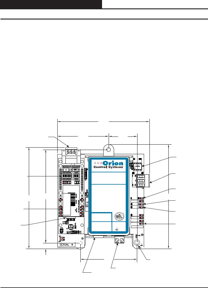
•The PT-Link II BACnet® interface is packaged and assembled as surface mount. Surface mount components are included for your convenience.
The PT-Link II BACnet® interface provides the following data sharing capabilities:
•Provides values from points on the Orion side of the gateway to BACnet® devices as if the values were originating from BACnet® objects.
•Allows BACnet® devices to modify point values on the Orion controller side of the PT-Link II BACnet® by using standard BACnet® write services.
•Computer running Microsoft WindowsTM operating system.
•Ethernet Crossover Cable (supplied).
•PT-Link II BACnet software—located on included CDROM and downloadable from www.orioncontrols.com/ software-new.html.
•* RUINET software— located on included CD-ROM and downloadable from www.orioncontrols.com/software-new. html.
*NOTE: RUINET is only needed for initial configuration if you need to set the address above 255 or if your BACnet lacks DIP switches. The config.csv file’s Server_DIP parameter is initially set to Enabled which allows the System_Node_ID (BACnet MAC Address) and Node_ID (Device Instance) to be set using the DIP Switches on the module.
PT-Link II Interface |
Revised 10/11/12 3 |
PT-Link II BACnet® Technical Guide
Setting Up Your PT-Link II
Quick Guide |
5. Connect your PT-Link II to your computer using an Ethernet |
|
connection (Figures 3 & 4). |
|
The following steps will get you up and running in no time:
1. |
Familiarize yourself with the PT-Link II components (Figure 1). |
6. |
Change your PCs IP Address. Follow the directions that match |
|
your current operating system - Windows NT, XP, Vista, or 7. |
||
2. |
Connect your PT-Link II to the Controller(s) on your system (up |
|
See directions on pages 7 & 8. |
|
|
||
|
to four) and connect your PT-Link II to the BACnet Network |
7. |
Obtain the following from your Building Automation System |
|
(Figure 2). |
|
Integrator: the BACnet MAC address (System Node ID), your |
3. |
If the BACnet address doesn’t need to be any higher than 255, |
|
server’s baud rate, and the Client Node ID. |
|
|
||
|
then you can use the DIP switch settings to configure your PT- |
8. |
Using RUINET, edit the Config.csv file and verify PT Link II |
|
Link II. Skip to page 9. Set the DIP Switches, wait 4 minutes, |
|
communications. Follow the directions on pages 10-13. |
|
and you’ll be up and running. If the address needs to be higher |
|
|
|
than 255, or your BACnet module does not have DIP switches, |
9. |
If you run into any problems, follow the instructions in the |
|
continue with Step 4. |
|
Troubleshooting section starting on page 14 of this guide. |
4.Copy the contents of the PT Link II CD to your PC’s Desktop. You can also download the files from http://orioncontrols.com/ software-new.html under PT-Link II Setup Files. These files include RUINET.
|
|
|
|
|
4.25 |
|
|
|
|
|
BACnet® |
|
|
|
|
|
|
|
|
|
|
Communications |
|
|
|
|
|
|
|
|
|
|
Wiring Terminal |
|
|
|
2.37 |
|
|
1.31 |
|
|
|
|
|
|
|
|
|
|
|
|
485 |
Local Loop |
|
|
|
|
|
|
|
|
|
Communications |
|
|
|
|
|
|
|
|
|
|
DRIVER |
|
|
|
|
RSGND |
|
|
|
|
|
|
Driver Chip |
|
|
|
ON |
|
www.orioncontrols.com |
|
|
|||
Configuration |
|
O N |
|
O N |
OE368-23B-BACNET |
COMM |
Local Loop |
|||
|
|
|
|
R |
||||||
|
1 2 3 4 5 6 7 8 |
1 2 3 4 |
PT-LINK II PROTOCOL |
Communications |
||||||
DIP Switches |
|
|
||||||||
|
|
|
|
TRANSLATOR |
SH |
Wiring Terminal |
||||
|
|
|
|
|
FOR BACNET |
|
|
|||
|
|
RX |
TX |
|
|
|
|
|
T |
|
|
|
|
|
|
|
|
|
|
|
|
|
|
|
|
|
LED BLINK CODES (NORMAL) |
|
Communications |
|||
|
|
|
|
|
LOOP |
=RAPID BLINK |
|
|||
|
|
|
|
|
|
LED |
||||
|
|
com.protocessor.www |
ESSORCROTOP CoprocessorProtocol |
|
PROTO |
=RAPID BLINK |
|
|||
|
4.31 |
|
LED 1 |
=BLINKS QTY |
|
Diagnostic |
||||
4.70 |
|
|
|
|
|
|
CONTROLLERS |
LOOP |
Diagnostic |
|
|
|
|
|
|
LED 2 |
= |
STEADY BLINK |
PROTO |
||
|
|
|
|
|
TIMER |
= |
STEADY BLINK |
LED1 |
LED #1 |
|
|
|
|
|
|
|
|
||||
BACnet® |
|
|
|
|
WATCH DOG = ON SOLID |
LED2 |
|
|||
|
|
|
|
|
|
|
|
|
||
|
|
|
|
H-BEAT |
= |
STEADY BLINK |
|
|
||
Protocessor |
|
|
|
|
|
|
|
|
TIMER |
LED #2 |
Module |
|
|
|
|
|
|
|
|
||
|
|
|
|
|
|
|
|
W_DOG |
|
|
|
|
|
|
|
|
|
|
|
|
|
|
|
|
|
|
|
|
|
|
H-BEAT |
|
Ethernet |
|
|
|
|
#LB102082 |
|
GND VAC |
POWER |
Power |
|
|
|
|
|
|
MADE IN USA |
|||||
|
|
|
|
|
WattMaster Label |
|
|
|||
Port |
|
|
|
|
Rev. 01A |
|
|
+24 |
|
LED |
|
|
|
|
|
|
|
|
|
|
|
|
0.27 |
|
|
|
|
|
|
|
|
|
|
|
|
|
|
2.61 |
|
|
0.20 Dia. |
||
|
|
|
|
|
|
|
|
|
|
Mounting Hole |
|
|
|
|
|
|
|
|
24 VAC Power |
Typ. 3 PL. |
|
|
|
|
|
|
|
|
|
|
||
|
|
|
|
|
USB |
|
|
Terminal |
|
|
|
|
|
|
|
Port |
|
|
|
|
|
Figure 1: PT-Link II BACnet® Dimensions and Components
4 |
Revised 5/11/11 |
PT-Link II Interface |
|
|
PT-Link II BACnet® Technical Guide
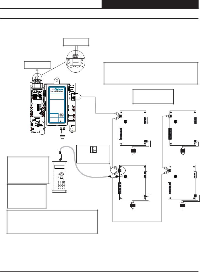
Connection and Wiring Information
MS/TP Connection
To BACnet® Network
MS/TP Connection
To BACnet® Network
PT-Link Interface
IMPORTANT WIRING NOTE:
Use the Daisy-Chain Topology As Shown in This Diagram. DO NOT Use a Star Topology with Multiple Units Tied Directly to the PT-Link II.
|
|
|
|
|
|
|
485 |
|
|
|
|
|
|
|
|
|
DRIVER |
|
|
|
RSGND |
|
|
|
|
|
|
|
|
|
|
ON |
|
|
|
|
|
Up To 4 Controllers |
|
O N |
|
O N |
www.orioncontrols.com |
COMM |
|
||||
|
|
|
PT-LINK II PROTOCOL |
R |
Can Be Interconnected. |
|
|||
1 2 3 4 5 6 7 8 |
1 2 3 4 |
OE368-23B-BACNET |
|
|
|
||||
|
|
|
TRANSLATOR |
SH |
Controller’s Address |
|
|||
RX |
TX |
|
FOR BACNET |
T |
|
||||
|
|
|
LED BLINK CODES (NORMAL) |
|
Cannot Be Higher Than 16. |
|
|||
|
|
|
LOOP |
=RAPID BLINK |
|
|
|
||
com.protocessor.www |
ESSORCROTOP CoprocessorProtocol |
|
PROTO |
=RAPID BLINK |
|
|
|
||
|
LED 1 |
=BLINKS QTY |
TIMER |
|
|
||||
|
|
|
|
|
CONTROLLERS |
LOOP |
|
|
|
|
|
|
LED 2 |
= STEADY BLINK |
PROTO |
Controller |
Controller |
||
|
|
|
TIMER |
= STEADY BLINK |
LED1 |
||||
|
|
|
WATCH DOG = ON SOLID |
LED2 |
|
|
|||
|
|
|
H-BEAT |
= STEADY BLINK |
|
|
|
||
|
|
|
|
|
|
|
W_DOG |
|
|
|
|
|
#LB102082 |
|
GND VAC |
H-BEAT |
|
|
|
|
|
|
WattMaster Label |
|
POWER |
|
|
||
|
|
|
Rev. 01A |
|
|
+24 |
MADE IN USA |
|
|
 24 VAC
 (10 VA)
Line Voltage
T |
|
|
SHLD |
24 VAC |
24 VAC |
R |
(8 VA) |
(8 VA) |
|
|
|
|
|
Typical Terminal Blocks. All |
Line Voltage |
Line Voltage |
Caution: The BACnet |
® |
|
|
|
Wiring To Be T To T, SHLD |
|
|
|
|
|
|
(G) To SHLD (G) & R To R |
|
|
|
Communication Terminal Block |
|
|
|
Controller |
Controller |
||
|
|
|
|
||||
Must Be Disconnected Before |
|
|
|
|
|
|
|
Connecting The Modular Service |
|
|
|
|
|
|
|
Tool. After Programming The |
Selection |
|
UP |
|
|
|
|
|
|
Mode |
|
|
|
|
|
Controller(s), Disconnect The |
STATUS |
PREV |
|
NEXT |
|
|
|
Service Tool and Then Reconnect |
SCHEDULES |
|
|
|
|
|
|
|
|
SETPOINTS |
|
|
|
|
|
The Communication Terminal |
|
ESC |
DOWN CLEAR |
|
|
||
|
|
ENTER |
|
|
|
||
|
|
OVERRIDES |
|
|
|
|
|
|
|
ALARMS |
1 |
2 |
3 |
|
|
|
|
CONFIGURATION |
4 |
5 |
6 |
|
|
Note: All Programming Of |
BALANCE - TEST |
7 |
8 |
9 |
|
|
|
ON |
DEC |
0 |
- |
|
|
||
|
|
|
|
MINUS |
|
|
|
Controllers Must Be Done |
|
|
|
|
|
|
|
Using The Modular Service |
Modular Service Tool |
|
|
||||
Tool. The Modular System |
|
|
|||||
|
|
|
|
|
|
||
Manager Should Not Be Used |
|
|
|
|
|
|
|
On A System That Has A PT- |
|
|
|
|
24 VAC |
24 VAC |
|
Link Installed. |
|
|
|
|
|
||
|
|
|
|
|
(8 VA) |
(8 VA) |
|
|
|
|
|
|
|
||
|
|
|
|
|
|
Line Voltage |
Line Voltage |
Wiring Notes: |
|
|
|
|
|
|
|
1.) All wiring to be in accordance with local and national electrical codes |
|
|
|||||
and specifications. |
|
|
|
|
|
|
|
2.) All communication wiring to be 18 gauge minimum, 2 conductor twisted pair with shield. Use Belden #82760 or equivalent.
Figure 2: PT-Link II BACnet® Interface Wiring
PT-Link II Interface |
Revised 8/31/11 |
5 |
PT-Link II BACnet® Technical Guide
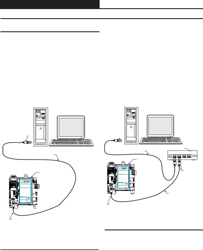
PT-Link II Ethernet Connection
PT-Link II Hardware Connection
You have two options for connecting the PT-Link II to your PC via Ethernet:
1.) You may connect the PT-Link II directly to your PC by using a crossover cable (by others) as shown. See Figure 3 for details.
2.) You can also connect both your PC and the PT-Link II to an Ethernet Hub with standard CAT5 cables. See Figure 4 for details.
Locate a CAT5 cable and plug one end into your computer’s Ethernet port (use a crossover cable if connecting directly to the PT-Link II). If connecting directly, plug the other end of the Cable into the Ethernet port on the PT-Link II. If connecting through an Ethernet Hub, plug the other end of the PC cable into the hub, and use a second CAT5 cable to connect the PT-Link II to the hub as well.
Power up the PT-Link II by plugging in the power cable. The PT-Link II may take up to three minutes to power up completely. Once the PT-Link II is powered up, depending on which type of BACnet module you have, you should notice that the green GP105 LED remains on or the RUN LED is blinking continuously on the ProtoCessor Board. See Figure 25 and 27 on pages 16 & 17 for a diagram showing the location of the ProtoCessor RUN or GP105 LED.
Desktop Or Laptop PC
Connect Ethernet
Crossover Cable Directly
To PC Ethernet Card Port
Ethernet Crossover Cable
PT-Link BACnet
|
|
|
|
|
|
|
|
485 |
|
|
|
|
|
|
|
|
DRIVER |
|
|
|
www.orioncontrols.com |
|
|
|||
|
|
|
|
|
|
|
|
COMM |
|
|
|
OE368-23B-BACNET |
R |
||||
|
|
|
PT-LINK II PROTOCOL |
|
||||
|
|
|
TRANSLATOR |
|
SH |
|||
|
|
|
FOR BACNET |
|
T |
|||
|
|
|
|
|
|
|
|
|
|
|
|
LED BLINK CODES (NORMAL) |
|
||||
|
|
|
LOOP |
=RAPID BLINK |
|
|
||
com.protocessor.www |
CoprocessorProtocol |
ESSORCROTOP |
PROTO |
=RAPID BLINK |
|
|
||
LED 1 |
=BLINKS QTY |
|
TIMER |
|||||
|
|
|
|
|
CONTROLLERS |
LOOP |
||
|
|
|
LED 2 |
= |
STEADY BLINK |
PROTO |
||
|
|
|
TIMER |
= |
STEADY BLINK |
LED1 |
||
|
|
|
WATCH DOG = ON SOLID |
|
LED2 |
|||
|
|
|
H-BEAT |
= |
STEADY BLINK |
|
||
|
|
|
|
|
|
|
|
W_DOG |
|
|
|
|
|
|
|
|
H-BEAT |
|
|
|
WattMaster Label |
GND |
VAC |
POWER |
||
|
|
|
#LB102082 |
|
MADE IN USA |
|||
|
|
|
Rev. 01A |
|
|
|
+24 |
|
Desktop Or Laptop PC
Connect Ethernet
Cable To Ethernet
Hub Port 
Ethernet Hub
Ethernet Cable
1 |
2 |
3 |
4 |
|
|
|
|
|
|
PT-Link BACnet |
|
|
|
|
|
|
485 |
|
|
|
|
|
|
|
DRIVER |
|
|
|
|
|
www.orioncontrols.com |
R |
Connect Ethernet |
||
|
|
|
OE368-23B-BACNET |
||||
|
|
|
|
|
COMM |
|
|
|
|
|
PT-LINK II PROTOCOL |
T |
Cables To |
Ethernet |
|
|
|
|
TRANSLATOR |
SH |
|
|
|
|
|
|
FOR BACNET |
|
|
|
|
|
|
|
LED BLINK CODES (NORMAL) |
|
Hub Ports |
|
|
|
|
|
LOOP |
=RAPID BLINK |
|
|
|
com.protocessor.www |
CoprocessorProtocol |
ESSORROTOCP |
PROTO |
=RAPID BLINK |
|
|
|
LED 1 |
=BLINKS QTY |
|
|
|
|||
|
|
|
|
CONTROLLERS |
LOOP |
|
|
|
|
|
LED 2 |
= STEADY BLINK |
PROTO |
|
|
|
|
|
TIMER |
= STEADY BLINK |
LED1 |
|
|
|
|
|
WATCH DOG = ON SOLID |
LED2 |
|
|
|
|
|
|
H-BEAT |
= STEADY BLINK |
|
|
|
|
|
|
|
|
TIMER |
|
|
|
|
|
|
|
W_DOG |
|
|
|
|
|
|
GND VAC |
H-BEAT |
|
|
|
|
|
|
POWER |
|
|
|
|
|
|
|
+24 |
MADE IN USA |
|
|
|
|
|
|
|
|
Ethernet Cable |
|
Connect Ethernet
Crossover Cable
To PT-Link Ethernet
Port
Connect Ethernet
Crossover Cable
To PT-Link Ethernet
Port
Figure 4: Connecting With Ethernet Cable & Hub
Figure 3: Connecting With Crossover Cable
6 Revised 4/25/11 |
PT-Link II Interface |
PT-Link II BACnet® Technical Guide
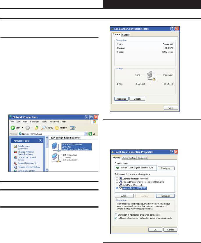
IP Address Configuration
Computer IP Address Set-up for Windows XP, Vista, and 7
In order for the PT-Link II to communicate properly, it is imperative to set the IP address of both the PT-Link II as well as the computer to be within the same netmask. You need to change the IP address on your computer. The following instructions will explain how to configure the IP address for Microsoft® Windows XP, Vista, and 7 operating systems.
Computer IP Address Set-up for Windows NT & XP
1.) Click <start>; then click <Control Panel>.
2.) Double-click on the Network Connections icon. The Network Connections Window will appear (Figure 5).
Figure 5: Network Connections Window
Figure 6: Local Area Connection Status Window
4.) As shown in Figure 6, click <Properties> in the lower left of the window. The Local Area Connection Properties Window will appear.
NOTE: If any wireless connections are listed, disable them by right-clicking the connection and selecting
<Disable>.
3.) In the Network Connections Window, double-click the
Local Area Connections entry. The Local Area Connection Status Window will appear (Figure 6).
Figure 7: Local Area Connection Properties Window
5). As shown in Figure 7, in the Connection Items list box, be sure the Internet Protocol (TCP/IP) is checked. Select the Internet Protocol (TCP/IP) item to highlight it and then click
<Properties>. The Internet Protocol Properties Window will appear.
PT-Link II Interface |
7 |
PT-Link II BACnet® Technical Guide
IP Address Configuration
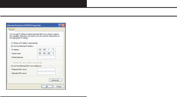
Figure 8: Internet Protocol Properties Window
6). Select the radio button in front of Use the following
IP address (Figure 8) and write down the current defaults so that you can re-enter them when you finish configuring the PT-Link and then type in the following
information:
a.) |
IP address 192.168.1.5 |
b.) |
Subnet mask 255.255.255.0 |
c.) |
Default Gateway is blank |
7.) Click <OK> until all of the above network configuration windows are closed. You may have to reboot the computer before the new values are valid.
Computer IP Address Set-up for Windows Vista & 7
1.) Click <start>; then click <Control Panel>.
2.) Click on the Network and Internet icon.
3.) Click Network and Sharing Center.
4.) From the shaded box in the left side of the window, select
Manage Network Connections (Vista) or Change adapter settings (Windows 7).
5.) Right-click on the Local Area Connection icon and select
<Properties> for the drop down window.
6.) Choose Internet Protocol Version 4 (TCP/IPv4) by highlighting it and then click <Properties>. The Internet Protocol Properties Window will appear (Figure 8).
7.) Select the radio button in front of Use the following
IP address (Figure 8) and write down the current defaults so that you can re-enter them when you finish configuring the PT-Link and then type in the following
information:
a.) |
IP address 192.168.1.5 |
b.) |
Subnet mask 255.255.255.0 |
c.) |
Default Gateway is blank |
9.) Click <OK> until all of the above network configuration windows are closed. You may have to reboot the computer before the new values are valid.
8 |
PT-Link II Interface |
PT-Link II BACnet® Technical Guide
Configuring the PT-Link DIP Switches
PT-Link DIP Switch Configuration
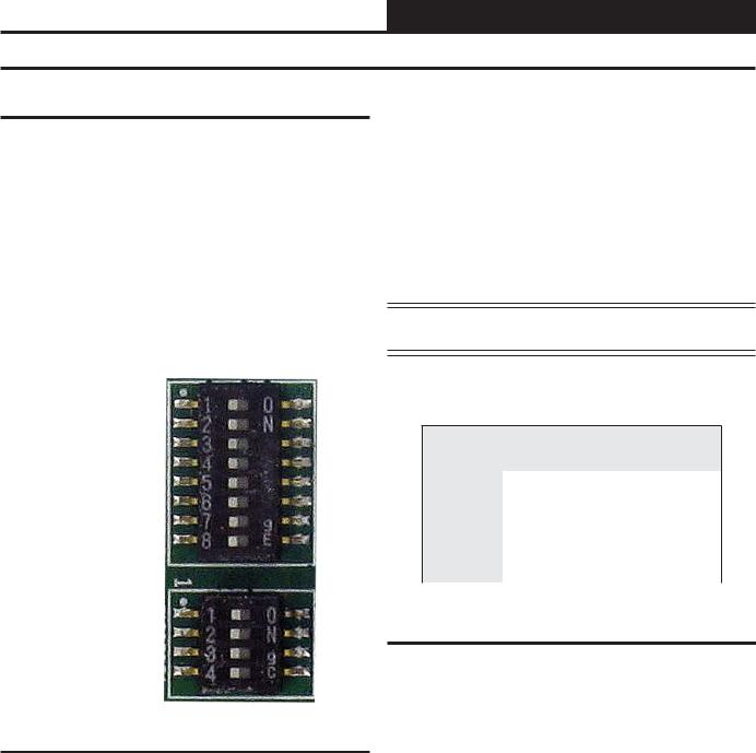
If the BACnet address doesn’t need to be any higher than 255, then follow these directions to use the DIP Switch settings to configure your PT-Link II. The DIP Switches are shown in Figure 9.
The config.csv file’s ‘Server_DIP’ parameter will default to ‘Enabled’ which will allow the System_Node_ID (BACnet MAC Address) and Node_ID (Device Instance) to be set using the DIP Switches on the module. See Figure 17 on page 12. With this capability, RUINET is not needed for the initial configuration. Set the DIP Switches, power up the PT-Link II, wait 4 minutes, and your PT-Link II BACnet is ready.
The DIP Switches allow you to set the Baud Rate, Node-ID (Device Instance), and MAC address on the Field RS-485 protocol as well as to automatically download configuration files for certain protocols.
The DIP Switches are designated by Bank A & B. Bank A is used to select both the MAC Address and Device Instance – if using the DIP switches these will always be the same. The maximum legal value is 255. See Appendix C for each possible combination for the addresses.
Bank B is used to set the Server Baud rate. For setting serial field protocol baud rate, the DIP Switches B1 – B4 can be set for the following speeds. See Table 2 for Server Baud rate settings.
DIP
Switch
Bank A 
DIP
Switch
Bank B 
NOTE: You must cycle power after making changes to the DIP
Switch Settings for the settings to take effect.
FFP-485
Using B1 – B4 to Set Baud Rate
Baud |
B4 |
B3 |
B2 |
B1 |
9600 |
ON |
ON |
ON |
ON |
19200 |
ON |
OFF |
OFF |
OFF |
38400 |
ON |
OFF |
ON |
ON |
57600 |
ON |
ON |
OFF |
OFF |
76800 |
ON |
ON |
OFF |
ON |
Table 2: Baud Rate Settings
Figure 9: DIP Switches
PT-Link II Interface |
Revised 4/25/11 |
9 |
PT-Link II BACnet® Technical Guide
Running RUINET
Connecting To The PT-Link II
NOTE: The preferred method of configuration is to use the DIP Switches on the Protocessor board unless your address setting needs to be greater than 255.
1.) In order to communicate and program the PT-Link II you will need to install RUINET software on your computer. If you do not have the software, it is available for downloading at www.orioncon- trols.com/software-new.html under PT-Link II Software
WARNING: Make sure to load RUINET onto your hard drive and run the program from your hard drive. DO NOT under any circumstances run RUINET from your cd drive.
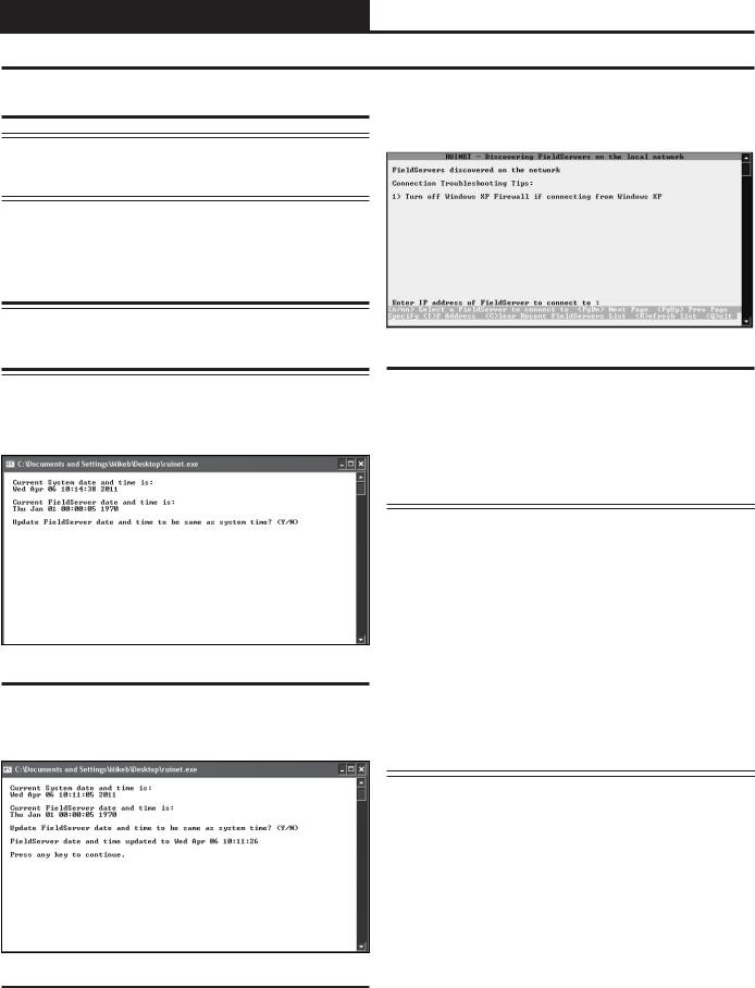
2.) If RUINET is in the desktop directory (if it isn’t, locate its directory), double-click on RUINET, and the RUINET program should run. Initially, you might see the screen below (Figure 10).
4.) The following screen may appear (Figure 12). Type <I> for Specify IP Address and the message “Enter IP Address of the Field Server to Connect to” will appear on the screen.
Figure 12: RUINET PT-Link Specify IP Address
5.) Type the IP Address of <192.168.1.24> and press <Enter>.
6.) If you have only one PT-Link connected to the network, then RUINET will automatically connect to that particular PT-Link; otherwise, a menu will appear to allow the selection of the desired PT-Link.
Figure 10: Update FieldServer Date and Time
3.) Type <Y> to sync the Date/Time on your PC. The following screen will appear (Figure 11). Press any key to continue.
NOTE: If RUINET is unable to establish a connection, there are a few simple procedures you can perform to try to determine the problem. To verify your network cables, observe the green LED displayed directly above and to the right of the Ethernet port. This LED should be on if the 10 BaseT cable is good. Secondly, observe the red LED displayed directly above and to the left of the Ethernet port. This LED should be solid while RUINET is running. If the LEDs are lit as expected, and RUINET still does not receive replies, then the netmask is probably incorrect. If this does not help, then your Ethernet setup on your PC is possibly not compatible. Ensure that you have an Ethernet adapter installed in your software configuration and that it is configured to run the TCP/IP protocol. If you are still unable to connect, please contact WattMaster Controls.
Figure 11: FieldServer Date and Time Updated
10 Revised 4/25/11 |
PT-Link II Interface |
PT-Link II BACnet® Technical Guide
Changing the Config.csv File
7.) On subsequent connections, a list of PT-Links that have been recently connected may appear under the message “Recently connected to FieldServers. Select the required PT-Link by typing the Number or Letter in the left hand column. (Figure 13).
9.) Type the letter <U> to upload the Config file (Figure 15), then type <U> again (Figure 16) for Upload.
Figure 15: RUINET PT-Link Main Menu - Upload
Figure 13: RUINET PT-Link Selection Menu
8.) Once connected, you will see the RUINET Main Menu (Figure 14). Unless you need to make changes to the config.csv file (steps 7 through 15), you are now ready to send and receive files to and from the PT-Link.
|
|
Figure 16: RUINET PT-Link Upload |
Figure 14: RUINET PT-Link II Main Menu |
|
10.) You will get confirmation that the upload is complete. Type <N> |
|
to open the file in Notepad. |
|
|
|
|
|
|
|
|
|
WARNING: Only edit the config.csv file using Notepad. DO |
|
|
NOT use Excel. Using Excel to edit the config.csv file will cor- |
|
|
rupt its contents! |
|
|
|
|
|
|
PT-Link II Interface |
11 |
PT-Link II BACnet® Technical Guide
Changing the Config.csv File
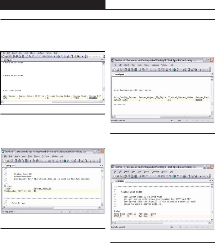
11.) Inside the text file under ‘Connections’, you must change the ‘Server_DIP’ parameter from ‘Enabled’ to ‘Disabled’ and then you can use RUINET to configure the addresses and baud rate. (See
Figure 17).
Figure 17: Changing the ‘Server_DIP’ parameter
12.) Inside the text file you can change the System_Node_ID (the BACnet MAC address) which defaults to 11 (Figure 18). You can obtain this information from your Building Automation System (BAS) Integrator.
13.) If the server baud rate needs to be changed, go to the ‘Connections’ section and only change the SERVER_BAUD (Figure 19). Possible Baud Rate values are (9600, 19200, 38400, 76800). The default Baud Rate is 38400. You can obtain this information from your BAS Integrator.
Figure 19: Changing the Baud Rate in Notepad
14.) The last change you may need to make is the Node_ID under ‘Client Side Nodes’ which is the BACnet Device Instance Number (Figure 20). The default is 1.You can obtain this information from your BAS Integrator.
Figure 18: Changing the BACnet MAC address
Figure 20: Changing the Node ID in Notepad
12 |
Revised 4/25/11 |
PT-Link II Interface |
PT-Link II BACnet® Technical Guide
Verifying PT-Link Communications
15.) Once the changes are made to the text file, click <File> in the upper left and then click <Save>. Now close the file and return to the RUINET Main Menu.
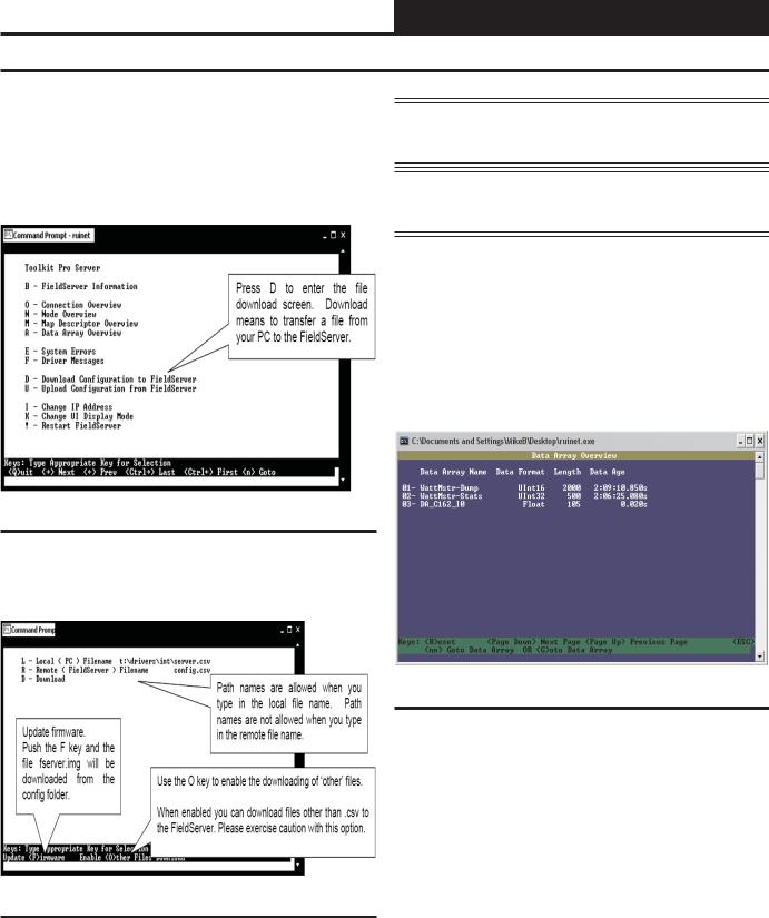
16.) From the RUINET Main Menu, type <D> to Download the new config.csv file to the FieldServer (Figure 21).
NOTE: The utility will indicate when downloading is complete. DO NOT reset the PT-Link until this message is displayed, as this will corrupt the PT-Link.
NOTE: The Remote Filename option must always be named “config.csv” for configurations; otherwise, it will be ignored by the PT-Link.
18.) Once the download is complete, restart the PT-Link II by cycling power or press <Esc> to get back to the RUINET Main Menu and then type <!> option to save the new configuration file and restart RUINET. It is possible to do multiple downloads to the PT-Link II before resetting it. There will be a start-up period where you will be unable to connect to the PT Link.
19.) From the RUINET Main Menu, type <A> for the Data Array Overview. The Data Array Overview Screen will display (Figure 23).
Figure 21: Download new Config.csv file
17.) At the next screen, (Figure 22), type <D> again.
Figure 23: Data Array Overview Screen
20.) This screen (Figure 23) will verify communication to the HVAC units. Lines 1 & 2 should always be present. After a start-up period of approximately 4 minutes, you will see 1 additional line for each HVAC unit. This screen represents the PT Link II communicating with 1 HVAC unit.
21.) Once these steps have been completed and you have verified that the reconfigured PT Link II has established communication to the HVAC unit(s), it can now be added to the BAS network.
Figure 22: Download new Config.csv file
PT-Link II Interface |
13 |

PT-Link II BACnet® Technical Guide
Troubleshooting the PT-Link Controller
Addressing WattMaster Devices in a
BACnet® Network.
Each PT-Link II BACnet® generates only one BACnet® device regardless of the number of WattMaster controls connected to it. This device will have all the properties of all the WattMaster controls connected. The instance of the device is equal to the unit address. The properties of each control can be differentiated by an offset of 500.
Examples:
1.) Properties of the controller address as 1 will range from 0 to 499.
2.) Properties of the controller address as 2 will range from 500 to 999.
3.) Properties of the controller address as 3 will range from 1000 to 1499.
To search for the instance of a specific property, follow the next formula:
Property Instance = ((Controller Address – 1) * 500) + Instance Number from table.
Example:
1.) The PT-Link II BACnet® has a Node ID equal to five.
2.) Two VCM controllers connected and addressed to one and four.
3.) Searching for the Outdoor Temperature of each controller.
4.) Instance of the Outdoor Temperature in the VCM table equal to AI: 54.
5.) Client will only see Device 5.
6.) Under Device 5 it will see AI: 54 for the Outdoor Temperature of the unit addressed as 1 and AI: 1554 for the Outdoor Temperature of the unit addressed as 4.
NOTE: To simplify the calculation, we recommend that the WattMaster controllers be addressed in sequential order from one to the last controller without any unused address(es) in between.
14 |
PT-Link II Interface |
PT-Link II BACnet® Technical Guide
Troubleshooting the PT-Link II Controller
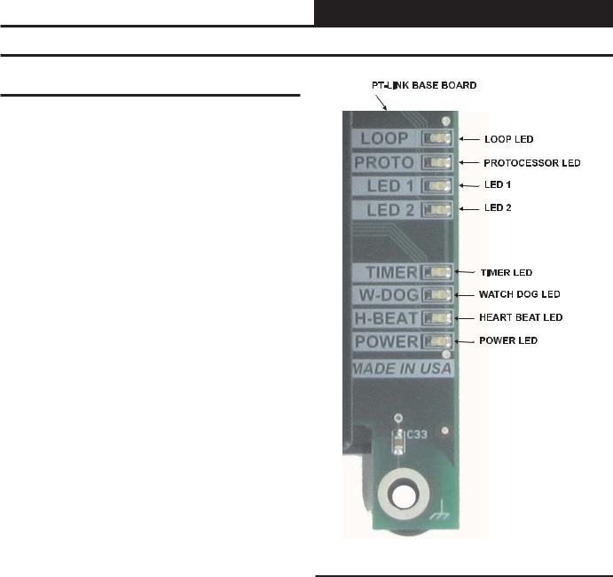
PT-Link II Board LEDs
The PT-Link II BACnet® is equipped with LEDs that can be used for troubleshooting. There are eight LEDs on the PT-Link board. See Figure 24 for the locations of the LEDs on the PT-Link board. The LED descriptions and functions are listed in the following paragraphs.
POWER LED
When the PT-Link II BACnet® is powered up, the “POWER” LED should light up and stay on continuously. If it does not light up, check to be sure that you have 24 VAC connected to the board, that the wiring connections are tight, and that they are wired for correct polarity. The 24 VAC power must be connected so that all ground wires remain common. If after making all these checks the “POWER” LED still does not light up, please contact WattMaster Controls Technical Support at our Toll Free number—866-918-1100—for assistance.
LOOP LED
When power is applied to the PT-Link II BACnet®, the “LOOP” LED will also light up. The LED should flicker rapidly, indicating that the PT-Link is trying to communicate with the controllers on the loop. A “flicker” is defined as a brief moment when the LED turns off and back on. If the “LOOP” LED does not operate as indicated above, first power down the unit and then reapply power. If this does not work, please contact WattMaster Controls Technical Support at our Toll Free number—866-918-1100—for assistance.
LED 1
When power is first applied, “LED 1” will be off temporarily and then will blink one time for each controller it is communicating with. For example, if you have 4 controllers on the loop connected to the PT-Link, “LED 1” will blink 4 times. If the amount of blinks does not match the number of controllers connected to the loop, it indicates there is a communications problem. The best way to find out which board is not communicating is to go to each controller and look at its “COMM” LED. The “COMM” LED should be solid and will flicker occasionally indicating communication with the PT-Link II BACnet®. If the “COMM” LED does not flicker, there is no communication with that controller.
LED 2
When power is first applied, “LED 2” will be off temporarily and then will blink slowly indicating that the PT-Link baseboard is communicating with the ProtoCessor Module. If “LED 2” does not blink, check that the ProtoCessor Module is installed correctly on the PT-Link baseboard and that the “PWR” LED is lit up on the ProtoCessor Module.
PROTO LED
When the PT-Link II is first powered up, the “PROTO” LED should blink rapidly and may appear to be on solid. This LED verifies communication with the board and the ProtoCessor. If the LED doesn’t light up, check that the ProtoCessor is installed correctly and firmly connected to the Base Board. The “PWR” LED should also be lit on the ProtoCessor Module.
TIMER LED
The “TIMER” LED is used for troubleshooting by WattMaster Controls Technical Support. The “TIMER” LED should always be blinking steadily.
Figure 24: PT-Link II BACNET® LED Locations
WATCH DOG LED
The “W-DOG” LED is used for troubleshooting by WattMaster Controls Technical Support. The “W-DOG” LED should always be on solid.
HEARTBEAT LED
The “H-BEAT” LED blinks to show the PT-Link II board software is running. If the LED doesn’t light up, and all other checks have been made, please contact WattMaster Controls Technical Support at our Toll Free number—866-918-1100—for assistance.
PT-Link II Interface |
Revised 8/13/12 15 |

PT-Link II BACnet® Technical Guide
Troubleshooting the PT-Link II Controller - OE368-23B-BACnet
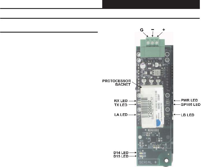
ProtoCessor Module LEDs
Refer to Figure 25 for LED locations. NOTE: If your BACnet module does not have DIP switches, refer to Figure 27 on page 17.
PWR LED
When the PT-Link II is first powered up, the “PWR” green LED should light up and stay on continuously. If the LED doesn’t light up, check that the ProtoCessor is installed correctly and firmly connected to the Base Board.
UNUSED LEDs
15 seconds after powering up, the 4 unused LEDs will turn on solid for 5 seconds, then turn off.
RX & TX LEDs
During normal operation, the “RX” LED will flash when a message is received on the field port of the ProtoCessor and the “TX” LED will flash when a message is sent on the field port of the ProtoCessor The “TX” and “RX” LEDs work together to indicate that communication is being established with the desired protocol network. If both LEDs are blinking, then communication is working properly. If not, check the protocol network wiring and the baud rate in the configuration file.
RUN LED
The “RUN” LED will flash 20 seconds after power up, signifying normal operation. The Protocessor will be able to access RUINET once this LED starts flashing. During the first 20 seconds, the LED should be off.
SYS ERR LED
The “SYS ERR” LED will go on solid 15 seconds after power up. It will turn off after 5 seconds. A steady red light will indicate there is a system error on the ProtoCessor. If this occurs, immediately report the related “system error” shown in the error screen of the Remote User Interface to FieldServer Technologies for evaluation.
COMM ERR
The “COMM ERR” LED will go on solid 15 seconds after power up. It will turn off after 5 seconds. A steady red light will indicate a communications problem if there is a configured node connected to the ProtoCessor that is offline. To establish the cause of the error, go to the error screen of the Remote User Interface interface.
CONFIG ERR LED
The “CONFIG ERR” LED will go on solid 15 seconds after power up. It will turn off after 5 seconds. A steady amber light will indicate a configuration error exists in the active configuration. See the Error Screen in the Remote User Interface for a description of the configuration error.
NODE OFFLINE LED
The “NODE OFFLINE” LED will go on solid 15 seconds after power up. It will turn off after 5 seconds. If the Node Offline LED stays on solid, a node offline condition has occurred.
NOTE: If all of these tests are made and the controller still doesn’t operate, please contact WattMaster Controls Technical Support at our Toll Free number—866-918-1100—for assistance.
G – +
RX & TX LEDs
PROTOCESSOR
BACNET
RUN LED |
PWR LED |
|
SYS ERR LED |
|
|
COMM ERR LED |
UNUSED |
|
CONFIG ERR LED |
||
|
||
NODE OFFLINE LED |
|
Figure 25: PT-Link II BACNET® LED Locations
Figure 26: PT-Link II BACNET® Protocessor Components
16 |
Revised 11/2/11 |
PT-Link II Interface |
PT-Link II BACnet® Technical Guide
Troubleshooting the PT-Link II Controller - OE368-23-BACnet
ProtoCessor Module LEDs
Refer to Figure 27 for LED locations. NOTE: If your BACnet module has DIP switches, refer to Figure 25 on page 16.
PWR LED
When the PT-Link II is first powered up, the “PWR” LED should light up and stay on continuously. If the LED doesn’t light up, check that the ProtoCessor is installed correctly and firmly connected to the Base Board.
GPI05 LED
The “GPI05” LED will light up when the Base Board and the ProtoCessor Module have established communications. This can take up to 3 minutes depending on the number of units connected to the PT-Link II. If it fails to light up after 3 minutes, check that the ProtoCessor is installed correctly and firmly to the Base Board.
LB LED
Once the unit is powered up, the “LB” LED must be blinking constantly. If this LED is constantly on or off, the Module is not working properly and needs to be replaced.
LA LED
Once the unit is powered up, the “LA” LED must be blinking constantly. If this LED is constantly on or off, the Module is not working properly and needs to be replaced.
TX & RX LEDs
The “TX” and “RX” LEDs work together to indicate that communication is being established with the desired protocol network. If both LEDs are blinking, then communication is working properly. If not, check the protocol network wiring and the baud rate in the configuration file.
D14 & D15 LEDs
The “D14” and “D15” LEDs work together to indicate that commu- |
Figure 27: PT-Link II BACNET® LED Locations |
||
nication is being transmitted and received from the USB Port when |
|
||
|
|||
performing an update to the PT-Link software. |
|
||
|
|
|
|
|
|
|
|
NOTE: |
If all of these tests are made and the controller |
|
|
|
still doesn’t operate, please contact WattMaster |
|
|
|
Controls Technical Support at our Toll Free num- |
|
|
|
ber—866-918-1100—for assistance. |
|
|
|
|
|
|
|
|
|
|
PT-Link II Interface |
17 |

PT-Link II BACnet® Technical Guide
Troubleshooting the PT-Link II Controller
Using RUINET
Before continuing with the troubleshooting, make sure the PT-Link is connected correctly and the RUINET software is installed, running, and functioning correctly.
Verifying Proper Communications
From the RUINET Main Screen, press <O> to go the Connection Overview Screen. This screen supplies information on communication between the PT-Link and remote devices. A number of aspect screens are available, and some of the aspect screens have more than one page. Use the space bar to toggle between aspects and use the <PgUp> and <PgDn> keys to toggle between pages of the same aspect. The Connection Overview and Settings Aspect Screen is shown in Figure 28.
The main purpose in this screen is to verify that messages and characters are being transmitted and received. In addition, it shows the number of communication errors. If the PT-Link connection “03” is the protocol connection, verify that is communicating appropriately. If it is not, check that the PT-Link LEDs are working properly, the unit is wired correctly, and the PT-Link is configured correctly (Baud Rate, Unit Address & MAC Address). If the number of errors is constantly increasing, move to the Error Screen by pressing the <Space Bar> 3 times to find out the cause of the errors. Use the <PgUp> and <PgDn> keys to toggle between pages of the Error Screen.
Verifying Proper Values
To verify that the correct values for each unit are being communicated to the PT-Link, move to the Data Array Overview Screen. To get to the screen, press <A> from the RUINET Main Menu. See Figure 29 for screen details.
In the Data Array Overview Screen (Figure 29) you will be able to see the data arrays of all the units connected to the PT-Link denoted by an array name “DA_XXX_IY”—Y being the address of the unit minus one. The Address of the unit is determined by a set of DIP switches. To view the values being communicated from a specific unit, move to the Data Array Detail Screen (Figure 30) of the unit by entering the number under which it is listed. For example, for the unit listed in the third position, enter <03>.
To understand what each value means, look at the Data Array Tables for the desired unit type, VCM-X, SA, or VCM. You can change the writable values from this screen by using the modify command. To use the modify command, press <M> from the Data Array Detail Screen and then enter the Offset you want to change followed by a space and the new value.
Example: To change the Cooling Supply Setpoint to 60 in the VCM, press <M>, enter <58 60>, and then press <Enter>. This could be useful to prove that the unit can take and keep the setpoints properly.
Figure 28: Connection Overview Screen
Figure 29: Data Array Overview Screen
Figure 30: Data Array Detail Screen
18 |
PT-Link II Interface |
 Loading...