


 Loading...
Audio Video Control Receiver
TX-SV373
Audio Video Karaoke Control
Receiver
TX-SE350
Instruction Manual
MASTER VOLUME
STANDBY/ON |
PRESET |
STANDBY
TUNING
POWER
SCAN GROUP
ALL CHANNEL HIGH CURRENT DISCRETE OUTPUT STAGE
 ON OFF
A SPEAKERS B |
SURROUND MODE |
CENTER MODE |
DELAY TIME |
MEMORY FM MUTE/MODE |
CLEAR |
TREBLE |
BASS |
PHONES |
MULTI CH INPUT |
DVD |
VIDEO 1 |
VIDEO 2 |
TAPE(MONITOR) |
FM |
AM |
PHONO |
C D |
AUDIO VIDEO CONTROL RECEIVER TX-SV373
|
|
|
|
|
|
|
|
|
|
|
|
|
|
|
MASTER VOLUME |
STANDBY/ON |
|
|
|
|
|
|
|
|
|
|
|
PRESET |
|
|
|
|
|
|
|
|
|
STANDBY |
|
|
|
|
|
|
|
|
|
POWER |
KEY CONTOL |
VACAL |
|
|
|
|
|
|
|
TUNING |
|
|
|||
|
|
|
|
CANCEL |
|
|
ALL CHANNEL HIGH CURRENT DISCRETE OUTPUT STAGE |
SCAN |
GROUP |
|
|||||
|
|
|
|
|
|
|
|
|
|
|
|||||
ON |
OFF |
|
|
|
|
|
|
|
|
|
|
|
|
|
|
|
1 |
MIC LEVEL |
2 |
ECHO LEVEL |
A SPEAKERS |
B |
SURROUND MODE |
CENTER MODE |
|
DELAY TIME |
MEMORY FM MUTE/MODE |
|
|||
KARAOKE |
|
|
|
|
|
|
|
|
|
|
|
|
CLEAR |
|
|
|
|
|
|
|
|
|
|
|
|
|
|
|
BASS |
TREBLE |
|
|
MIN |
MAX MIN |
MAX |
MIN |
MAX |
|
|
|
|
TAPE(MONITOR) |
|
|
|
C D |
|
PHONES |
1 |
MIC |
2 |
|
|
MULTI CH INPUT |
DVD |
VIDEO 1 |
VIDEO 2 |
FM |
AM |
PHONO |
|
||
|
|
|
|
|
|
|
|
|
|
|
|
||||
A/V KARAOKE CONTROL RECEIVER TX-SE350
Thank you for purchasing the Onkyo Audio Video Control Receiver.
Please read this manual thoroughly before making connections and turning on the power.
Following the instructions in this manual will enable you to obtain optimum performance and listening enjoyment from your new Audio Video Control Receiver.
Please retain this manual for future reference.
Contents |
|
Before using |
|
Important Safeguards........................ |
2 |
Precautions ....................................... |
3 |
Features............................................. |
4 |
Supplied accessories......................... |
4 |
Before operating this unit ................. |
5 |
Preparation |
|
Audio equipment connections |
.......... 6 |
Video equipment connections .......... |
7 |
Connecting Other Devices................ |
8 |
Connecting speakers....................... |
10 |
Positioning speakers ....................... |
11 |
Connecting the power..................... |
11 |
Connecting antennas....................... |
12 |
Operation |
|
Listening to your favorite source.... |
14 |
To enjoy Surround mode or |
|
Stereo mode ................................. |
16 |
Tuning in a radio station................. |
18 |
Using preset radio stations.............. |
19 |
Karaoke function (TX-SE350 only)... |
20 |
Recording a source ......................... |
22 |
Using TAPE (MONITOR) Button..... |
23 |
Using the Remote Controller.......... |
24 |
A few important notes |
|
Control positions and names .......... |
26 |
Troubleshooting guide.................... |
27 |
Specifications ................................. |
28 |
WARNING:
TO REDUCE THE RISK OF FIRE OR ELECTRIC SHOCK, DO NOT EXPOSE THIS APPLIANCE TO RAIN OR MOISTURE.
CAUTION:
TO REDUCE THE RISK OF ELECTRIC SHOCK, DO NOT REMOVE COVER (OR BACK). NO USER-SERVICEABLE PARTS INSIDE. REFER SERVICING TO QUALIFIED SERVICE PERSONNEL.
WARNING |
|
AVIS |
RISK OF ELECTRIC SHOCK |
|
RISQUE DE CHOC ELECTRIQUE |
DO NOT OPEN |
|
NE PAS OUVRIR |
|
|
|
The lightning flash with arrowhead symbol, within an equilateral triangle, is intended to alert the user to the presence of uninsulated “dangerous voltage” within the product’s enclosure that may be of sufficient magnitude to constitute a risk of electric shock to persons.
The exclamation point within an equilateral triangle is intended to alert the user to the presence of important operating and maintenance (servicing) instructions in the literature accompanying the appliance.
Important Safeguards
1.Read Instructions – All the safety and operating instructions should be read before the appliance is operated.
2.Retain Instructions – The safety and operating instructions should be retained for future reference.
3.Heed Warnings – All warnings on the appliance and in the operating instructions should be adhered to.
4.Follow Instructions – All operating and use instructions should be followed.
5.Water and Moisture – The appliance should not be used near water – for example, near a bathtub, washbowl, kitchen sink, laundry tub, in a wet basement, or near a swimming pool, and the like.
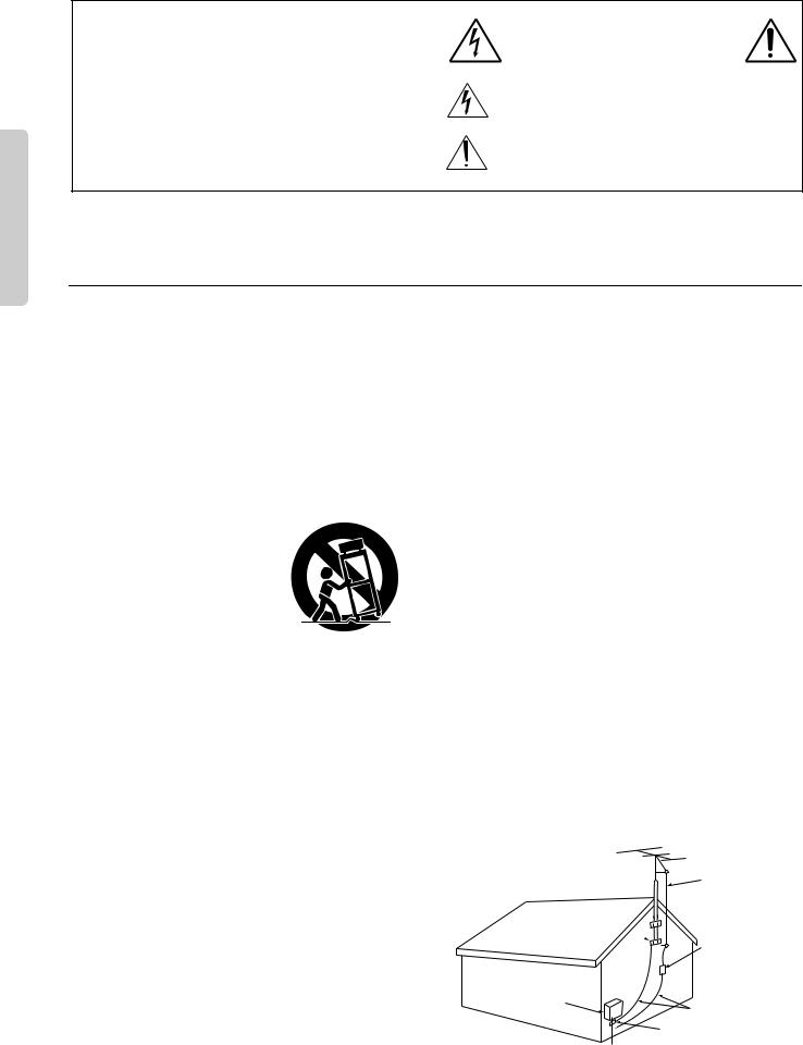
6.Carts and Stands – The appliance should be used only with a
cart or stand that is recommended by the manufacturer.
6A. An appliance and cart combination should be moved with care. Quick stops, excessive force, and uneven surfaces may cause the appliance and cart combination to overturn.
|
S3125A |
7. |
Wall or Ceiling Mounting – The appliance should be mounted |
|
to a wall or ceiling only as recommended by the manufacturer. |
8. |
Ventilation – The appliance should be situated so that its loca- |
|
tion or position does not interfere with its proper ventilation. |
|
For example, the appliance should not be situated on a bed, |
|
sofa, rug, or similar surface that may block the ventilation |
|
openings; or if placed in a built-in installation, such as a book- |
|
case or cabinet that may impede the flow of air through the |
|
ventilation openings, there should be free space of at least 20 |
|
cm (8 in.) and an opening behind the appliance. |
9. |
Heat – The appliance should be situated away from heat |
|
sources such as radiators, heat registers, stoves, or other appli- |
|
ances (including amplifiers) that produce heat. |
10. |
Power Sources –The appliance should be connected to a |
|
power supply only of the type described in the operating |
|
instructions or as marked on the appliance. |
11. |
Polarization – If the appliance is provided with a polarized |
|
plug having one blade wider than the other, please read the fol- |
|
lowing information: |
|
The polarization of the plug is a safety feature. The polarized |
|
plug will only fit the outlet one way. If the plug does not fit |
|
fully into the outlet, try reversing it. If there is still trouble, the |
|
user should seek the services of a qualified electrician. Under |
|
no circumstances should the user attempt to defeat the polar- |
|
ization of the plug. |
12. |
Power-Cord Protection – Power-supply cords should be |
|
routed so that they are not likely to be walked on or pinched by |
|
items placed upon or against them, especially near plugs, con- |
|
venience receptacles, and the point where they exit from the |
|
appliance. |
13. |
Cleaning – The appliance should be cleaned only as recom- |
2 |
mended by the manufacturer. |
|
14.Power Lines – An outdoor antenna should be located away from power lines.
15.Nonuse Periods – The power cord of the appliance should be unplugged from the outlet when left unused for a long period of time.
16.Object and Liquid Entry – Care should be taken so that objects do not fall and liquids are not spilled into the enclosure through openings.
17.Damage Requiring Service – The appliance should be serviced by qualified service personnel when:
A.The power-supply cord or the plug has been damaged; or
B.Objects have fallen, or liquid has been spilled into the appliance; or
C.The appliance has been exposed to rain; or
D.The appliance does not appear to operate normally or exhibits a marked change in performance; or
E.The appliance has been dropped, or the enclosure damaged.
18.Servicing – The user should not attempt to service the appliance beyond that described in the operating instructions. All other servicing should be referred to qualified service personnel.
19.Outdoor Antenna Grounding – If an outside antenna is connected to the receiver, be sure the antenna system is grounded so as to provide some protection against voltage surges and built up static charges. Article 810 of the National Electrical Code, ANSI/NFPA 70, provides information with regard to proper grounding of the mast and supporting structure, grounding of the lead-in wire to an antenna-discharge unit, size of grounding conductors, location of antenna-discharge unit, connection to grounding electrodes, and requirements for the grounding electrode. See Figure 1.
FIGURE 1:
EXAMPLE OF ANTENNA GROUNDING AS PER NATIONAL ELECTRICAL CODE
ANTENNA
LEAD IN
WIRE
GROUND  CLAMP
CLAMP 
ANTENNA DISCHARGE UNIT (NEC SECTION 810-20)
ELECTRIC
SERVICE
EQUIPMENT
GROUNDING CONDUCTORS (NEC SECTION 810-21)

 GROUND CLAMPS

 POWER SERVICE GROUNDING
ELECTRODE SYSTEM
(NEC ART 250, PART H)
NEC – NATIONAL ELECTRICAL CODE
S2898A

Precautions
1. Warranty Claim
You can find the serial number on the rear panel of this unit. In case of warranty claim, please report this number.
2. Recording Copyright
Recording of copyrighted material for other than personal use is illegal without permission of the copyright holder.
3. AC Fuse
The fuse is located inside the chassis and is not user-serviceable. If power does not come on, contact your Onkyo authorized service station.
4. Care
From time to time you should wipe the front and rear panels and the cabinet with a soft cloth. For heavier dirt, dampen a soft cloth in a weak solution of mild detergent and water, wring it out dry, and wipe off the dirt. Following this, dry immediately with a clean cloth. Do not use rough material, thinners, alcohol or other chemical solvents or cloths since these could damage the finish or remove the panel lettering.
5. Power WARNING
BEFORE PLUGGING IN THE UNIT FOR THE FIRST TIME, READ THE FOLLOWING SECTION CAREFULLY.
The voltage of the available power supply differs according to country or region. Be sure that the power supply voltage of the area where this unit will be used meets the required voltage (e.g., AC 230 V, 50 Hz or AC 120 V, 60 Hz) written on the rear panel.
Worldwide models are equipped with a voltage selector to conform to local power supplies. Be sure to set this switch to match the voltage of the power supply in your area before plugging in the unit.
The power cord should be removed from the AC outlet when the unit is not used for a prolonged time.
For British model
Replacement and mounting of an AC plug on the power supply cord of this unit should be performed only by qualified service personnel.
IMPORTANT
The wires in the mains lead are coloured in accordance with the following code:
Blue : Neutral Brown : Live
As the colours of the wires in the mains lead of this apparatus may not correspond with the coloured markings identifying the terminals in your plug, proceed as follows:
The wire which is coloured blue must be connected to the terminal which is marked with the letter N or coloured black.
The wire which is coloured brown must be connected to the terminal which is marked with the letter L or coloured red.
IMPORTANT
A 5 amp fuse is fitted in this plug. Should the fuse need to be replaced, please ensure that the replacement fuse has a rating of 5 amps and that it is approved by ASTA or BSI to BS1362. Check for the ASTA mark or the BSI mark on the body of the fuse.
IF THE FITTED MOULDED PLUG IS UNSUITABLE FOR THE SOCKET OUTLET IN YOUR HOME THEN THE FUSE SHOULD BE REMOVED AND THE PLUG CUT OFF AND DISPOSED OF SAFELY. THERE IS A DANGER OF SEVERE ELECTRICAL SHOCK IF THE CUT OFF PLUG IS INSERTED INTO ANY 13 AMP SOCKET.
If in any doubt, please consult a qualified electrician.
For U.S. model
Note to CATV system installer:
This reminder is provided to call the CATV system installer’s attention to Article 820-40 of the NEC, ANSI/NFPA 70, which provides guidelines for proper grounding and, in particular, specifies that the cable ground shall be connected to the grounding system of the building, as close to the point of cable entry as practical.
FCC Information for User
CAUTION:
The user changes or modifications not expressly approved by the party responsible for compliance could void the user's authority to operate the equipment.
NOTE:
This equipment has been tested and found to comply with the limits for a Class B digital device, pursuant to Part 15 of the FCC Rules. These limits are designed to provide reasonable protection against harmful interference in a residential installation. This equipment generates, uses, and can radiate radio frequency energy and, if not installed and used in accordance with the instructions, may cause harmful interference to radio communications. However, there is no guarantee that interference will not occur in a particular installation. If this equipment does cause harmful interference to radio or television reception, which can be determined by turning the equipment off and on, the user is encouraged to try to correct the interference by one or more of the following measures:
•Reorient or relocate the receiving antenna.
•Increase the separation between other equipment and the receiver.
•Connect the equipment into an outlet on a circuit different from that to which the receiver is connected.
•Consult the dealer or an experienced radio/TV technician for help.
For Canadian model
For models having a power cord with a polarized plug:
CAUTION: TO PREVENT ELECTRIC SHOCK, MATCH WIDE BLADE OF PLUG TO WIDE SLOT, FULLY INSERT.
Modele pour les Canadien
Sur les modèles dont la fiche est polarisée:
ATTENTION: POUR ÉVITER LES CHOCS ÉLECTRIQUES, INTRODUIRE LA LAME LA PLUS LARGE DE LA FICHE DANS LA BORNE CORRESPONDANTE DE LA PRISE ET POUSSER JUSQU’AU FOND.
Declaration of Conformity
We, ONKYO EUROPE ELECTRONICS GmbH INDUSTRIESTRASSE 20 82110 GERMERING, GERMANY
declare in own responsibility, that the ONKYO product described in this instruction manual is in compliance with the corresponding technical standards such as EN55013, EN55020, EN60555-2, -3 and EN60065
GERMERING, GERMANY
K.OTSU
ONKYO EUROPE ELECTRONICS GmbH
3
Features
TX-SV373/TX-SE350
■5.1 CHANNEL DIRECT INPUTS and 5-channel drive give you the ability to simply hook up an external decoder (Dolby Digital, DTS, MPEG) and raise your home theater experience to the highest level and enjoy DVDs, advanced laserdiscs and upcoming digital TV to the fullest.
■DOLBY* PRO LOGIC for multichannel surround sound from a HiFi VCR, satellite broadcast, DVD or laserdisc player, or stereo TV broadcast.
■HIGH-CURRENT LOW-IMPEDANCE 6-OHM DRIVE for all channels — a feature found more often on costly, higher end equipment — handles the widest variety of speakers without distortion or cutting off.
■COSTLY DISCRETE OUTPUT STAGE CIRCUITRY for the front and surround channels, unlike many receivers in this class that use inexpensive ICs for the surround channels — assures that no channel information is compromised, and handles the wide dynamics of multi-channel movie soundtracks cleanly and effortlessly, plus keeps sound from distorting, even at high volume.
■90 WATTS MAXIMUM POWER to the front L/R/C channels into 6Ω at 1000 Hz, plus 40 watts per surround speaker into 6 ohms (EIAJ rating) — enough solid, clean power to drive your home theater speakers with authority and produce dynamically rich music, even at low volume levels, and more than enough for a thrilling home theater experience in most entertainment rooms.
■HALL SURROUND MODE for more spacious, concert-hall sound, with the added ambience of a live performance—great for classical music.
■3 AV INPUTS to hook up your DVD player, a HiFi VCR and Digital Satellite System (DSS), for example.
■30 FM/AM RANDOM PRESETS — especially convenient if there are a lot of radio stations in your area — you can assign a number, in any order, to each of your favorite FM and AM stations then access them simply at the touch of a button.
■
 (REMOTE INTERACTIVE) FULL-FUNCTION REMOTE CONTROL to operate the major functions of virtually any Onkyo component — logical button layout puts all the basic functions right at your fingertips — easy to use.
(TX-SE350 only)
■KARAOKE CAPABILITY with 2 microphone inputs, each with its own volume control, plus Digital Echo, Digital Key (pitch) control and Voice Canceler for more professional sounding karaoke.
*Manufactured under license from Dolby Laboratories.
“Dolby”, “Pro Logic” and the double-D symbol  are trademarks of Dolby Laboratories. Confidential Unpublished Works. ©1992-1997 Dolby Laboratories, Inc. All rights reserved.
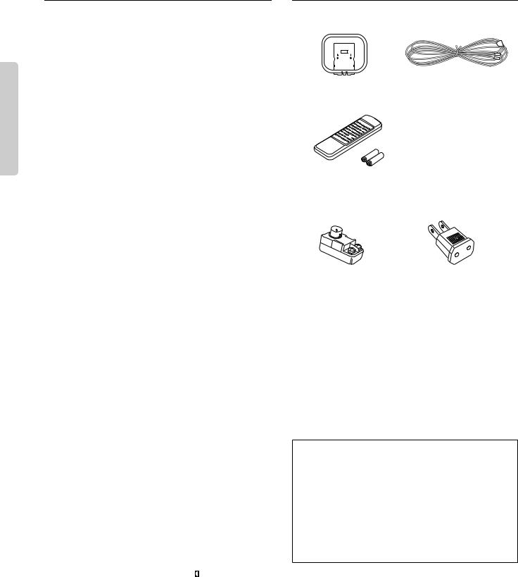
Supplied accessories
Check that the following accessories are supplied with this unit.
|
|
|
|
|
|
|
|
|
|
|
|
|
|
|
|
|
|
|
|
|
|
|
|
|
|
|
|
|
|
|
|
|
|
|
|
|
|
|
|
AM loop antenna × 1 |
T-shaped FM antenna × 1 |
||||||
Remote controller × 1
Batteries (size AA, R6, or UM-3) × 2
The following accessories are only available for worldwide models.
75/300 ohm antenna |
Conversion plug (Shape may |
adaptor × 1 |
vary depending on the area in |
|
which it was purchased.) × 1 |
Memory Preservation
This unit does not require memory preservation batteries. A built-in memory power back-up system preserves the contents of the memory during power failures and even when the unit is unplugged. The unit must be plugged in order to charge the back-up system.
The memory preservation period after the unit has been unplugged varies depending on climate and placement of the unit. On the average, memory contents are protected over a period of a few weeks after the last time the unit has been unplugged. This period is shorter when the unit is exposed to a highly humid climate.
4

Before operating this unit
|
|
|
|
|
|
|
|
|
9kHz |
10kHz |
|
|
|
|
|
|
|
|
|
|
|
|
AM |
|
|
|
|
|
|
|
|
|
|
|
FREQUENCY |
|
||
|
|
|
|
|
|
|
|
|
|
STEP |
|
|
ANTENNA |
|
|
|
|
|
|
|
|
|
|
|
|
|
|
|
|
FRONT SURROUND CENTER |
|
SURROUND |
CENTER |
|
|
|
||
|
|
|
|
|
|
|
SPEAKERS |
SPEAKER |
|
|
|
|
AM |
|
|
L |
|
|
|
R |
L |
|
|
|
|
|
|
|
|
|
|
|
|
|
|
9kHz |
10kHz |
|
|
|
|
R |
|
|
|
|
|
|
|
AM |
REMOTE |
|
|
|
|
|
|
|
|
|
|
FREQUENCY |
||
FM |
|
|
|
|
SUB |
SUB |
|
|
|
|
STEP |
CONTROL AC OUTLET |
75 |
|
|
|
|
|
|
|
|
||||
|
|
|
|
|
WOOFER |
WOOFER |
|
|
|
|
|
SWITCHED |
|
|
|
|
MULTICHANNEL INPUT |
PRE OUT |
R |
L |
|
|
|
100W MAX. |
|
|
V |
|
|
|
V |
|
|
|
MODEL NO. TX-SV262 |
|
|
|
|
|
|
|
|
|
|
|
|
|
|
|
|
GND |
|
MONITOR INPUT |
INPUT OUTPUT INPUT |
|
FRONT SPEAKERS |
|
|
|
||||
|
|
OUTPUT |
DVD |
VIDEO-1 |
VIDEO-2 |
|
R |
L |
|
|
|
|
|
OUTPUT INPUT |
|
|
|
|
|
|
|
|
|
|
|
|
(REC) |
(PLAY) |
|
|
|
A |
|
|
A |
|
|
|
L |
|
|
|
|
L |
|
|
|
|
VOLTAGE SELECTOR |
|
|
|
|
|
|
|
|
B |
|
|
B |
|
|
|
R |
|
|
|
|
R |
|
|
|
|
220-230V |
120V |
|
|
|
|
|
|
|
|
|
|
|
|
||
PHONO CD |
TAPE |
INPUT |
INPUT |
OUTPUT INPUT |
|
|
|
|
|
|
|
|
|
|
|
|
|
|
|
|
|
|
VOLTAGE SELECTOR |
||
|
|
|
|
|
|
|
|
|
220-230V |
|
120V |
|
|
|
|
|
1 |
|
|
|
|
|
|
|
|
|
|
|
|
2 |
|
|
|
– |
|
|
|
|
|
|
|
|
|
|
|
+ |
+ |
|
|
||
|
|
|
|
|
|
|
|
|
|
|
|
|
|
|
|
|
|
|
|
|
|
– |
|
|
|
|
|
|
|
3 |
|
|
|
|
|
|
|
|
|
|
|
|
|
|
|
|
|
– |
|
|
|
Remote control sensor |
TX-SV373/SE350 |
STANDBY indicator 
30˚ 30˚
approx. 5 m
(16 feet)
Setting the AM tuning step frequency (Worldwide models only)
Worldwide models are equipped with a switch that controls the AM band tuning steps. Please set this switch to match the AM band tuning step frequency in your area.
U.S.A. and Canada : 10 kHz
Other areas : 9 kHz
Setting the Voltage selector (Worldwide models only)
Worldwide models are equipped with a voltage selector to conform with local power supplies. Be sure to set this switch to match the voltage of the power supply in your area before plugging in the unit.
1. Determine the proper voltage for your area: 220-230 V or
120 V.
2.If the preset voltage is not correct for your area, insert a screwdriver into the groove in the switch. Slide the switch all the way to the right (120 V) or to the left (220-230 V), whichever is appropriate.
Installing the remote controller batteries
1.Remove the battery compartment cover by pressing the tab and lifting up the cover.
2.Insert two AA (R6or UM-3)-size batteries into the battery compartment. Carefully follow the polarity diagram (positive (+) and negative (–) symbols) inside the battery compartment.
3.After batteries are installed and seated correctly, replace the compartment cover.
Notes
•Do not mix new batteries with old batteries or different kinds of batteries.
•To avoid corrosion, remove the batteries if the remote controller is not to be used for a long time.
•Remove dead batteries immediately to avoid damage from corrosion. If the remote controller doesn’t operate smoothly, replace both the batteries at the same time.
•The life of the batteries supplied is about six months but this will vary depending on usage.
Using the remote controller
Point the remote controller toward the remote control sensor.
The STANDBY indicator lights up when the unit receives a signal from the remote controller.
Notes
•Place the unit away from strong light such as direct sunlight or inverted fluorescent light which can prevent proper operation of the remote controller.
•Using another remote controller of the same type in the same room or using the unit near equipment which uses infrared rays may cause operational interference.
•Do not put any object such as a book on the remote controller. The buttons of the remote controller may be pressed by mistake and drain the batteries.
•Make sure the audio rack doors do not have colored glass. Placing the unit behind such doors may prevent proper remote controller operation.
•If there is any obstacle between the remote controller and the remote control sensor, the remote controller will not operate.
5
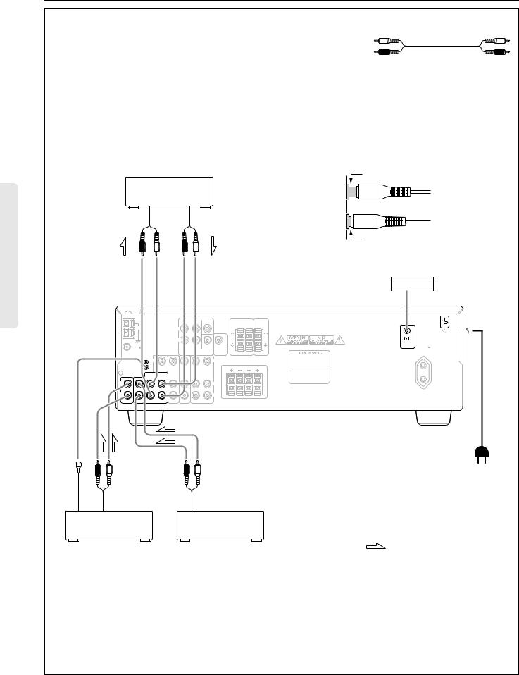
Audio equipment connections
•On each pair of connectors, a red connector (marked R) corresponds to the right channel, and a white connector (marked L) to the left channel.
•Please refer to the instruction manual for each component when you make any connections.
•This receiver is designed for use with turntables using moving magnet cartridges.
•Insert the plugs and connectors securely. Remember that improper connection could result in noise, poor performance, or damage to the equipment.
Audio connection cable |
|
L (Left) |
L |
R (Right) |
R |
|
|
|
|
|
|
|
|
|
Improper connection |
|
|
Tape Deck |
|
|
|
|
|
|
|||
INPUT |
|
|
|
|
OUTPUT |
|
|
|
|
|
(REC) |
|
|
|
|
(PLAY) |
|
|
|
|
|
R |
|
L |
R |
L |
|
|
|
Insert completely |
||
|
|
|
|
|
|
|||||
|
|
|
|
|
|
|
|
|
See page 9 |
|
ANTENNA |
|
|
|
|
|
|
|
|
|
|
|
|
|
|
FRONT SURROUND CENTER |
|
SURROUND |
CENTER |
|
||
|
|
|
|
|
|
|
SPEAKERS |
SPEAKER |
|
|
AM |
|
|
|
L |
|
|
R |
L |
|
|
|
|
|
|
|
|
|
|
|
||
|
|
|
|
R |
|
|
|
|
REMOTE |
|
|
|
|
|
|
|
|
|
|
AC OUTLET |
|
FM |
|
|
|
|
SUB |
SUB |
|
|
CONTROL |
|
|
|
|
|
|
|
AC 230V 50Hz |
||||
75 |
|
|
|
|
WOOFER |
WOOFER |
|
|
|
SWITCHED |
|
|
|
|
MULTICHANNEL INPUT |
PRE OUT |
R |
L |
|
100W MAX. |
|
|
V |
|
|
|
V |
|
|
|
MODEL NO. TX-SV262 |
|
|
|
|
|
|
|
|
|
|
|
|
GND |
MONITOR INPUT |
INPUT |
OUTPUT INPUT |
|
FRONT SPEAKERS |
|
||||
|
|
OUTPUT |
DVD |
VIDEO-1 |
VIDEO-2 |
|
R |
|
L |
|
|
OUTPUT |
INPUT |
|
|
|
|
|
|||
|
|
|
|
|
|
|
|
|
||
|
(REC) |
(PLAY) |
|
|
|
A |
|
|
A |
|
|
|
|
|
|
|
|
|
|
||
L |
|
|
|
|
L |
|
|
|
|
|
|
|
|
|
|
|
B |
|
|
B |
|
R |
|
|
|
|
R |
|
|
|
|
|
PHONO CD |
TAPE |
INPUT |
INPUT |
OUTPUT INPUT |
|
|
|
|
|
|
|
|
|
To wall |
|
|
|
outlet |
Ground |
OUTPUT |
OUTPUT (ANALOG) |
Do not plug in the power |
cord until all connections |
|||
|
|
|
have been made. |
|
Turntable |
CD Player |
|
|
|
|
: signal flow |
6
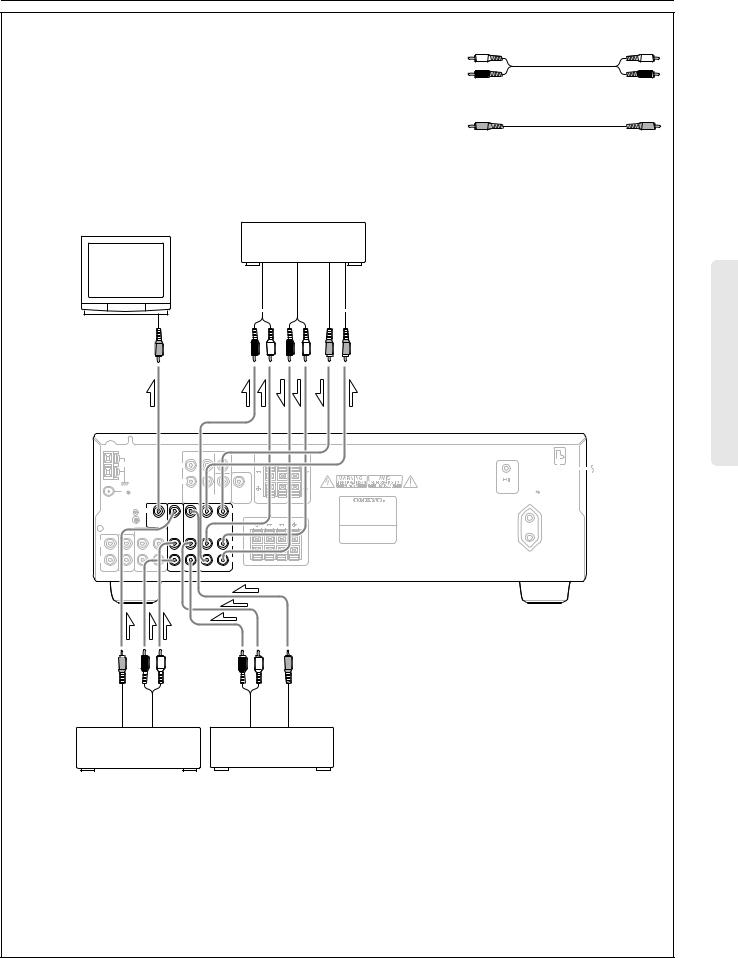
Video equipment connections
•On each pair of connectors, a red connector (marked R) corresponds to the right channel, and a white connector (marked L) to the left channel.
•A yellow connector (marked V) is used for video connection.
•Please refer to the instruction manual for each component when you make any connections.
Monitor TV
Video Cassette Recorder
(VIDEO-2)
AUDIO IN |
|
|
|
|
|
VIDEO IN |
|
|
|||||
AUDIO OUT |
|
|
|
|
|
VIDEO OUT |
|
|
|
|
|
VIDEO IN
Audio connection cable |
L |
L (Left) |
|
R (Right) |
R |
Video connection cable |
|
V (Video) |
V |
ANTENNA |
|
|
|
|
|
|
|
|
|
|
|
|
|
|
|
FRONT SURROUND |
CENTER |
|
SURROUND |
CENTER |
|
||
|
|
|
|
|
|
|
|
SPEAKERS |
SPEAKER |
|
|
AM |
|
|
|
L |
|
|
|
R |
L |
|
|
|
|
|
|
|
|
|
|
|
|
||
|
|
|
|
R |
|
|
|
|
|
REMOTE |
|
|
|
|
|
|
|
|
|
|
|
AC OUTLET |
|
FM |
|
|
|
|
|
SUB |
SUB |
|
|
CONTROL |
|
|
|
|
|
|
|
|
AC 230V 50Hz |
||||
75 |
|
|
|
|
|
WOOFER |
WOOFER |
|
|
|
SWITCHED |
|
|
|
|
MULTICHANNEL INPUT |
PRE OUT |
R |
L |
|
100W MAX. |
||
|
|
|
|
|
|
|
|
|
|
||
|
V |
|
|
|
|
|
V |
|
|
MODEL NO. TX-SV262 |
|
|
|
|
|
|
|
|
|
|
|
|
|
GND |
MONITOR |
INPUT |
INPUT |
OUTPUT |
INPUT |
|
FRONT SPEAKERS |
|
|||
|
|
OUTPUT |
DVD |
VIDEO-1 |
VIDEO-2 |
|
R |
|
L |
|
|
|
OUTPUT |
INPUT |
|
|
|
|
|
||||
|
|
|
|
|
|
|
|
|
|
||
|
(REC) |
(PLAY) |
|
|
|
|
A |
|
|
A |
|
|
|
|
|
|
|
|
|
|
|
||
L |
|
|
|
|
|
|
L |
|
|
|
|
|
|
|
|
|
|
|
B |
|
|
B |
|
R |
|
|
|
|
|
|
R |
|
|
|
|
PHONO CD |
TAPE |
INPUT |
INPUT |
OUTPUT |
INPUT |
|
|
|
|
|
|
VIDEO |
AUDIO |
AUDIO |
VIDEO |
OUT |
OUT |
OUT |
OUT |
 : signal flow
DVD Player
Video Disc Player
(VIDEO-1)
•This unit can be used only with a monitor TV equipped with a video input.
•If the receiver interferes with the TV reception, place the unit as far from the TV as possible. We do not recommend the use of a common TV/FM antenna (see the antenna section).
•When using a playback-only VCR, connect its output to the receiver’s video input connector.
7
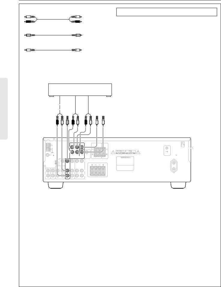
Connecting other devices
Audio connection cable |
L |
L (Left) |
|
R (Right) |
R |
Video connection cable |
|
V (Video) |
V |
Monaural audio cable (mono)
DVD player or a decoder with Multi channel outputs
A decoder with 5.1 channel output
•You may connect the 5.1 channel outputs of a DVD player or an external decoder (such as DOLBY Digital decoder or DTS decoder) to the MULTI CHANNEL INPUTs of the TX-SV373/ SE350.
•When using a DVD player or a decoder connected to the MULTICHANNEL INPUT connector, set the SPEAKERS A button on the front panel to ON.
AUDIO OUT |
|
|
|
|
|
|
|
SUBWOOFER OUT |
|
|
|
|
|
|
|||
VIDEO OUT |
|
|
|
|
|
|
CENTER OUT |
|
|
|
|
|
|
|
|||
MULTI CHANNEL |
|
|
|
|
|
|
SURROUND OUT |
|
|
|
|
|
|
|
|||
FRONT OUT |
|
|
|
|
|
|
||
|
|
|
|
|
|
|
|
|
ANTENNA
|
|
|
|
FRONT SURROUND |
CENTER |
|
SURROUND |
CENTER |
|
||
|
|
|
|
|
|
|
|
SPEAKERS |
SPEAKER |
|
|
AM |
|
|
|
L |
|
|
|
R |
L |
|
|
|
|
|
|
|
|
|
|
|
|
||
|
|
|
|
R |
|
|
|
|
|
REMOTE |
|
|
|
|
|
|
|
|
|
|
|
AC OUTLET |
|
FM |
|
|
|
|
|
SUB |
SUB |
|
|
CONTROL |
|
|
|
|
|
|
|
|
AC 230V 50Hz |
||||
75 |
|
|
|
|
|
WOOFER |
WOOFER |
|
|
|
SWITCHED |
|
|
|
|
MULTICHANNEL INPUT |
PRE OUT |
R |
L |
|
100W MAX. |
||
|
V |
|
|
|
|
|
V |
|
|
MODEL NO. TX-SV262 |
|
|
|
|
|
|
|
|
|
|
|
|
|
GND |
MONITOR |
INPUT |
INPUT |
OUTPUT |
INPUT |
|
FRONT SPEAKERS |
|
|||
|
|
OUTPUT |
DVD |
VIDEO-1 |
VIDEO-2 |
|
R |
|
L |
|
|
|
OUTPUT |
INPUT |
|
|
|
|
|
||||
|
|
|
|
|
|
|
|
|
|
||
|
(REC) |
(PLAY) |
|
|
|
|
A |
|
|
A |
|
|
|
|
|
|
|
|
|
|
|
||
L |
|
|
|
|
|
|
L |
|
|
|
|
|
|
|
|
|
|
|
B |
|
|
B |
|
R |
|
|
|
|
|
|
R |
|
|
|
|
PHONO CD |
TAPE |
INPUT |
INPUT |
OUTPUT |
INPUT |
|
|
|
|
|
|
8

Connecting other devices
AC outlet connection
ANTENNA
|
|
|
|
FRONT SURROUND |
CENTER |
|
SURROUND |
CENTER |
||
|
|
|
|
|
|
|
|
SPEAKERS |
SPEAKER |
|
AM |
|
|
|
L |
|
|
|
R |
L |
|
|
|
|
|
R |
|
|
|
|
|
|
FM |
|
|
|
|
|
SUB |
SUB |
|
|
|
75 |
|
|
|
|
|
WOOFER |
WOOFER |
|
|
|
|
|
|
|
MULTICHANNEL INPUT |
PRE OUT |
R |
L |
|
||
|
V |
|
|
|
|
|
V |
|
|
MODEL NO. TX-SV262 |
|
|
|
|
|
|
|
|
|
|
|
GND |
MONITOR |
INPUT |
INPUT |
OUTPUT |
INPUT |
|
FRONT SPEAKERS |
|||
|
|
OUTPUT |
DVD |
VIDEO-1 |
VIDEO-2 |
|
R |
|
L |
|
|
OUTPUT |
INPUT |
|
|
|
|
||||
|
(REC) |
(PLAY) |
|
|
|
|
A |
|
|
A |
|
|
|
|
|
|
|
|
|
||
L |
|
|
|
|
|
|
L |
|
|
|
|
|
|
|
|
|
|
B |
|
|
B |
R |
|
|
|
|
|
|
R |
|
|
|
PHONO CD |
TAPE |
INPUT |
INPUT |
OUTPUT |
INPUT |
|
|
|
|
|
You can connect the power cord from another audio device to the rear of the TX-SV373/SE350.
Since the AC outlet on the unit is a SWITCHED type outlet, you can use the STANDBY/ON button, or the POWER button on the remote controller to turn on/off the power to both the TX-SV373/SE350 and the connected audio device.
First turn the POWER switch ON (  ON ).
ON ).
The shape and capacity of the AC outlet may differ depending on the area of purchase. Make sure that the capacity of other components connected to this unit does not exceed the capacity that is printed on the rear panel.
REMOTE |
AC OUTLET |
CONTROL |
AC 230V 50Hz |
|
SWITCHED |
|
100W MAX. |
Worldwide and |
U.S.A. and |
European models |
Canadian models |
Capacity is total |
Capacity is total |
100 watts. |
120 watts. |
TX-SV373/SE350
ANTENNA
|
|
|
|
FRONT SURROUND |
CENTER |
|
SURROUND |
CENTER |
|
||
|
|
|
|
|
|
|
|
SPEAKERS |
SPEAKER |
|
|
AM |
|
|
|
L |
|
|
|
R |
L |
|
|
|
|
|
|
R |
|
|
|
|
|
REMOTE |
|
|
|
|
|
|
|
|
|
|
|
AC OUTLET |
|
FM |
|
|
|
|
|
SUB |
SUB |
|
|
CONTROL |
230V 50Hz |
75 |
|
|
|
|
|
WOOFER |
WOOFER |
|
|
|
ACSWITCHED |
|
|
|
|
MULTICHANNEL INPUT |
PRE OUT |
R |
L |
|
100W MAX. |
||
|
V |
|
|
|
|
|
V |
|
|
MODEL NO. TX-SV262 |
|
|
|
|
|
|
|
|
|
|
|
|
|
GND |
MONITOR |
INPUT |
INPUT OUTPUT INPUT |
|
FRONT SPEAKERS |
|
|||||
|
|
OUTPUT |
DVD |
VIDEO-1 |
VIDEO-2 |
|
R |
|
L |
|
|
|
OUTPUT |
INPUT |
|
|
|
|
|
|
|
|
|
|
(REC) |
(PLAY) |
|
|
|
|
A |
|
|
A |
|
|
|
|
|
|
|
|
|
|
|
||
L |
|
|
|
|
|
|
L |
|
|
|
|
|
|
|
|
|
|
|
B |
|
|
B |
|
R |
|
|
|
|
|
|
R |
|
|
|
|
PHONO CD |
TAPE |
INPUT |
INPUT |
OUTPUT |
INPUT |
|
|
|
|
|
|
CD Player
Cassette Tape Deck
Connections for remote control ( )
)
You can use the remote controller of this receiver to operate cassette tape decks, compact disc players, and DVD players that have Onkyo 
 connectors.
Connect a remote control cable to the black connector with the 
 mark on the rear panel.
•An 
 remote control cable equipped with a 3.5mm (1/8 in.)- diameter miniature two-conductor phone plug comes with every compact disc player or cassette tape deck that has an
 connector.
•Remote control operation is not possible when only the remote control cable is connected – the audio connection cables must also be connected.
•You cannot use the receiver’s remote controller to control Onkyo turntables.
DVD Player
9
Loading...