


TXNR-747
Table of contents
 Loading...
Ref.No. : 4537
AV RECEIVER
TX-NR747
✔ Pre Issue (2015-May)
✔ Final Issue (2015-Jun)
Service Manual
CONTENTS
✔ Front Cover (This page)
✔ Note for Parts List
✔ Panel
✔ Reset
✔ Amp Diag Mode after Abnormal Condi tion s
✔ Model and Destination
✔ Firmware
✔ Adjustment ( Unnecessary )
✔ Hookup and Setting
✔ Trouble Shoot
✔ Disassembly
✔ Schematic Diagram
✔ Exploded View
✔ Appendix
SAFETY-RELATED COMPONENT WARNING!! : COMPONENTS IDENTIFIED BY MARK ON
THE SCHEMATIC DIAGRAM AND IN THE PARTS LIST ARE CRITICAL FOR RISK OF FIRE AND
ELECTRIC SHOCK. REPLACE THESE COMPONENTS WITH ONKYO PARTS WHOSE PART
NUMBERS APPEAR AS SHOWN IN THIS MANUAL. MAKE LEAKAGE-CURRENT OR
RESISTANCE MESUREMENTS T O DETERMINE T HAT EXPOSED PARTS ARE ACCEPT ABLY
INSULATED FROM THE SUPPLY CIRCUIT BEFORE RETURNING THE APPLIANCE TO THE
CUSTOMER.
Published by Onkyo & Pioneer Corporation Grobal CS Department
1
2
5 4 3
6
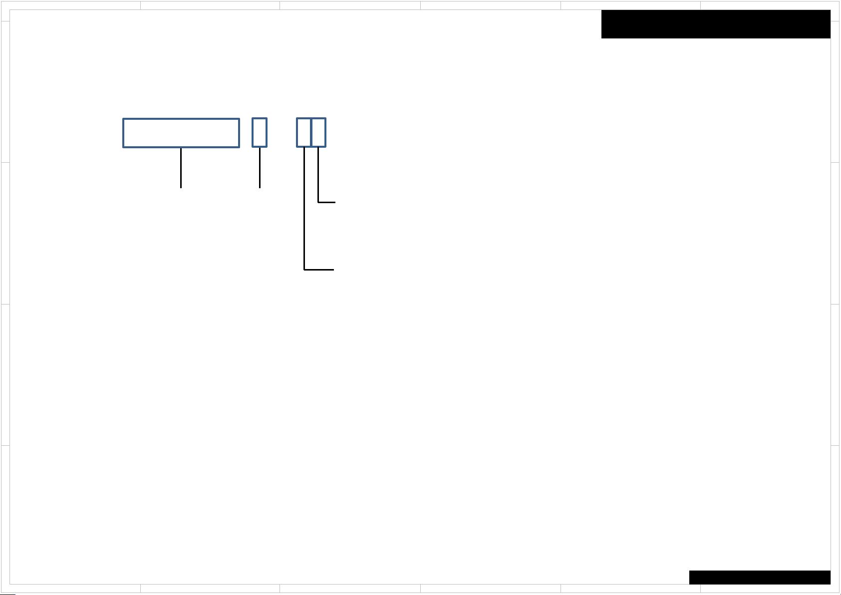
File Name of Parts List File (EXCEL File)
When parts list is EXCEL file, please refer to the following explanation about file name.
D
PL_TX-SR343(B)MJJ.xlsx
Destination
Model No. Color
C
Look at the rear panel serial number 6 digit.
○ ○ ○ ○ ○ J ○ ○ ○ ○ ○ ○ ○ ○ ○ ○
Voltage
Look at the rear panel serial number 5 digit.
○ ○ ○ ○ J ○ ○ ○ ○ ○ ○ ○ ○ ○ ○ ○
Note for Parts List
D
C
Color
(B) Black
(BR) Brown
B
A
(C) Cherry
(G) Gold
(GR) Green
(H) Gray
(K) Black
(L) Blue
(LB) Light Blue
(M) Wood
(O) Orange
(P) Pink
(R) Red
(S) Silver
(V) Violet
(W) White
(Y) Yellow
Voltage
J 100V AC
D 120V AC
M 220-240V AC
P 230V AC
U 100-240V AC
Speaker System (without AM P .) :
0 Passive Subw oofer
F Front Speaker
C Center Speaker
R Rear Speaker
B Back Speaker
Destination
J Japan
C North American
D USA
F Taiwan
S Brazil
Q Hong Kong
R China
A Australia
B United Kingdom
K Korea
L Russia
P Europe
U Worldwide
Speaker System (without AM P .) :
L Left channel
R Right channel
0 Center channel
B
A
COMMON
1
2
5 4 3
6

1
2
5 4 3
6
Front Panel / Rear Panel / Remote Control Unit
Front Panel
D
C
Panel
Remote Control Unit
RC-898M
D
C
Rear Panel
B
A
Weight : 435 mm × 175 mm × 379 mm, 17-1/8" × 6-7/8" × 14-15/16"
Dimensions (W × H × D) : 11.0 kg (24.3 lbs.) (North American and Taiwanese), 11.5 kg (25.4 lbs.) (Others)
1
2
Accessory
Indoor FM antenna --- (1)
AM loop antenna --- (1)
Remote controller (RC-898M) --- (1)
Batteries (AA/R6) --- (2)
Power cord (European and Taiwanese models) --- (1)
Speaker setup microphone --- (1)
The number in parenthesis indicates the quantity. On
packaging, the letter at the end of the product name
indicates the color.
TX-NR747
5 4 3
6
B
A

1
2
5 4 3
6
How to Reset the Unit
● How to reset:
D
Step1
While holding down CBL/SAT on the main unit (note that step 2 must be performed with
this button pressed down)
Step2
Press ON/STANDBY on the main unit. ("Clear" appears on the display and the unit returns
to standby.)
● Do not unplug the power cord until "Clear" disappears from the display.
C
● How to reset the remote controller:
Step1
While holding down RECEIVER on the remote controller, press Q until the remote
indicator stays lit (about 3 seconds).
Step2
Within 30 seconds, press RECEIVER again.
B
A
Reset
●リセット方法 :
1.
本体のCBL/SATボタンを押しながら(必ず押した状態で2.の操作を行ってください)
2.
本体のON/STANDBYボタンを押す(表示部に「Clear」が表示されてスタンバイ状態に
戻ります)
● 表示部から「Clear」が消えるまで、絶対に電源コードを抜かないでください。
●リモコンのリセット方法 :
1.
リモコンのRECEIVERボタンを押しながら、リモートインジケーターが点灯するまでQボ
タンを3秒以上押す
2.
30秒以内にRECEIVERボタンをもう一度押すとリセットされる
D
C
B
A
COMMON
1
2
5 4 3
6
1
2
5 4 3
6
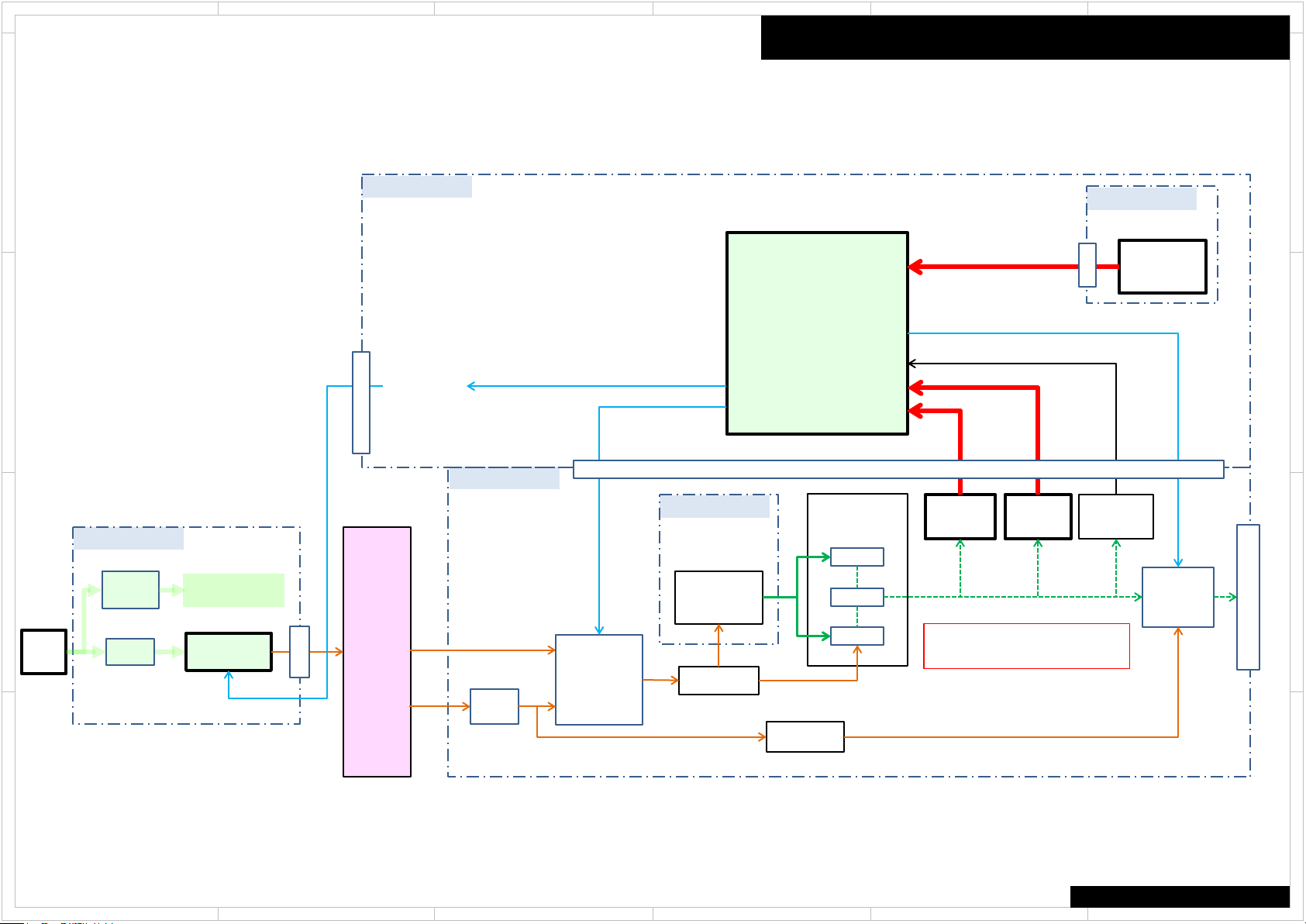
Protect Mode
Amp Diag Mode after Abnormal Conditions
The unit goes into standby automatically when detect the abnormal condition of thermal detection, dc voltage detection or current detection. (e.g. TX-SR343 block diagram below)
D
BAPRC-1758
THERMAL
C
B
AC IN
BAPS-1737
SUB
TRANS.
FUSE
F9001
Power Supply
for STANDBY
Relay
RL9001
MPU
Q7009
M POWER M POWER
P9011
SEC1H
BAAF-1712
BACLA-1734
Power amp.
POWER
TRANS.
T901
VOLTAGE
DRIVE
SEC-1
P9002
(HIGH)
SEC-1
(LOW)
FUSE
F6401
F6402
(H)
RELAY
RL6430
RL6440
(L)
(H)
or
(L)
Power
Supply
Power
Supply
SPRLF
VOLH
VPROTECT
IPROTECT
P8002
(Front L)
Q6050
P6080
Q6060
CURRENT
DETECT
IPRO
DC
DETECT
VPRO
VPRO : DC voltage detection
IPRO : Current detection
BAETC-1713
THERMAL
DETECT
P501
VOLTAGE
DETECT
VOLH
Q6300
RELAY
RL6600
(FL/FR)
D
C
B
SPEAKER - OUT
A
A
COMMON
1
2
5 4 3
6
1
2
5 4 3
6
Self-diagnostics
This function is for avoiding the rupture of electrolytic capacitors with amplifier circuit
failure during power-ON.
Operation of Self-diagnostic
D
Self-diagnostic will start at the timing of next power on, after goes to the protect mode
by Current detection or DC voltage detection.
Only On/Standby key could work in this mode. Also remote control does not work.
However, the CLEAR operation is enabled.
During Self-diagnostic, the power supply for amplifier circuit become low voltage
state(SEC1-LOW), and the speaker relay will be turned off. Then, MPU will check each
amplifier circuits Internally by entering the test signal (20 kHz,-20 dBFS sine wave) to
each channel from DSP.
C
MPU will judge the amplifier circuit is good or not from VOLH value.
The normal range of VOLH value is 0.04 V < VOLH < 0.20 V.
If VOLH value is in the out of this range, it will be judged as NG (No good).
No problem found
When protected by current detection, and no problem found, "CHECK SP WIRE“ will be displayed.
In this State, Only the On/Standby key is effective. And if do not an
into standby automatically.
When protected by a DC voltage detection, and no problem found, unit goes into normal
B
operation.
Problem found
When judged as there is a problem on any channel, the information of channel that has a problem
will be displayed as in the right figure.
In this State, Only the On/Standby key is effective. Also remote control does not work. If do not
anything for 3 minutes, unit goes into standby automatically. This state will keep also after unit
turn on/off, or AC unplugged.
the power supply for amplifier circuit become low voltage state(SEC1-LOW), and the speaker
A
relay will be turned off.
ything for 3 minutes, unit goes
Amp Diag Mode after Abnormal Conditions
Display of during Self-diagnostics
2 Line FL tube type
A M P D i a g M o d e
1 Line FL tube type
A M P D i a g M o d e
“Mode” This part display the channel which is currently checked. (E.g. "[FL]", etc.)
Display of when problem found
2 Line FL tube type
N G C H :
L C R S L S R B L B
1 Line FL tube type
N G : L C R S L S R B L B R
Front L channel
L
Center channel
C
Front R channel
R
S L
S R
B L
B R
Surround L channel
Surround R channel
Surround back L channel
Surround back R channel
R
D
C
B
A
COMMON
1
2
5 4 3
6

1
2
5 4 3
6
Repair Process and How to Confirm
Confirmation of the protect cause
While NG channel is displayed, You can confirm the protect cause by following the step below.
1. Press the Enter button
D
2. The protect cause are displayed for 5 seconds.
Please check the around of those amplifier circuit and repair it.
C
Clear of NG CH information
After repair, you can clear NG CH information by following the steps below.
1. Press the On/Standby key while pressing the Enter key.
2. Display as in the right figure appears.
3. Unit goes into Standby automatically after 5 seconds.
Self-diagnostic will start again at the timing of next power on.
By this, You can verify whether repair was properly or not.
If problem found after repair, please re-check the around of its circuit.
B
Cancel of Self-diagnostic
You can cancel this mode by clear operation (press Standby key while pressing CBL/SAT key).
After cancel this mode, receiver will be started as normal operation.
Amp Diag Mode after Abnormal Conditions
Protected by current detection
D E T . P R O T E C T : I
Protected by DC Voltage detection
D E T . P R O T E C T : V
Clear of NG CH information
N G C H C L E A R
D
C
B
A
A
COMMON
1
2
5 4 3
6

1
R 5 4 5 D C 2 0 0 0
D F 0 0 0 0
x x 8 0 0 0
D D 2 0 4 0
x x 8 0 4 0
D C 2 2 0 0
D F 0 2 0 0
J J 4 2 0 0
x x 8 2 0 0
D D 2 2 4 0
J J 4 2 4 0
x x 8 2 4 0
D C 2 4 0 0
D F 0 4 0 0
x x 8 4 0 0
D D 2 4 4 0
x x 8 4 4 0
2
5 4 3
6
How to check model and destination
D
C
B
[TV] + [ON/STANDBY] → [DIMMER] or [RT/PTY/TP] → [TONE +] x 4
Model Name Distination
TX-NR545
TX-NR545
TX-NR545
DTR-20.7
DTR-20.7
TX-NR646
TX-NR646
TX-NR646
TX-NR646
DTR-30.7
DTR-30.7
DTR-30.7
TX-NR747
TX-NR747
TX-NR747
DTR-40.7
DTR-40.7
DC
DF
xx
DD
xx
DC
DF
JJ
xx
DD
JJ
xx
DC
DF
xx
DD
xx
N
N R 5 4 5
N R 5 4 5
D T R 2 0 7
D T R 2 0 7
N R 6 4 6
N R 6 4 6
N R 6 4 6
N R 6 4 6
D T R 3 0 7
D T R 3 0 7
D T R 3 0 7
N R 7 4 7
N R 7 4 7
N R 7 4 7
D T R 4 0 7
D T R 4 0 7
FL Display
Model and Destination
D
C
B
A
TX-NR545/646/747
DTR-20.7/30.7/40.7
1
2
5 4 3
6
A

1
2
5 4 3
6
How to check Firmware Version & Preparation of Update
Step1 : [DISPLAY] + [ON/STANDBY] x 2
D
Main Firmware Version will appear on the main unit’s display.
Step2 : [TONE +]
NET Firmware Version will appear on the main unit’s display.
Step3 : [TONE +]
DSP Firmware Version will appear on the main unit’s display.
C
Step4 : [TONE +]
VIDEO Firmware Version will appear on the main unit’s display.
Step5 : [TONE +]
OSD Firmware Version will appear on the main unit’s display.
Step6 : [TONE +]
VS100 Firmware Version will appear on the main unit’s display.
( DTR-40.7 only )
B
A
Firmware
[Preparation of Update]
1. Connect the USB storage device to your PC. If there is any data in the USB storage device,
remove it.
2. Download the firmware file (package file) from the Onkyo FTP-server.
However European service partners should download the firmware file (package file) from
the ExtraNet.
Onkyo FTP-server: ftp://manex.onkyo.co.jp/_servicefwa/TX-NR545
ID and Password are those we informed when changed.
Filename is as follows: ONKAVR001D_****************.zip
Unzip the downloaded file. A following file is created.
ONKAVR001D_************.of1
ONKAVR001D_************.of2
ONKAVR001D_************.of3
ONKAVR001D_************.of4
ONKAVR001D_************.of5
3. Copy it to the USB storage device. Be careful not to copy the zip file.
4. Remove the USB storage device from your PC.
D
C
B
A
TX-NR545/646/747
DTR-20.7/30.7/40.7
1
2
5 4 3
6

1
2
5 4 3
6
How to Update (service mode)
Overwriting is also possible.
D
1. Turn on the unit. It takes some time to start after you switch on the unit.
2. Select the USB input source.
3. Connect the USB storage device to USB port on the unit. Wait until Initializing of USB/NET
finishes.
C
4. Hold down [DISPLAY] button and then press [ON/STANDBY] button twice.
Main version will be displayed, and HYBRID STANDBY indicator will start to flash.
5. Press [RETURN] button. “NET -> ALL_D” will be displayed.
6. Select “USB -> ALL_D” by [PRESET(left/right)] cursors and [TUNING(up/down)] cursors,
then press [ENTER] button, updating will begin.
7. Wait until update is completed. When the update ends, “Completed!” is displayed.
B
(If you leave it, it automatically turns standby mode. )
8. Press [ON/STANDBY] button, and the unit turns on.
9. Check the new FW version number.
<Note>
If the procedure might not be successful, please select “USB -> ALL_M”.
Firmware
D
C
B
A
A
TX-NR545/646/747
DTR-20.7/30.7/40.7
1
2
5 4 3
6

1
2
5 4 3
6
No Sound
■ No sound from connected player
D
C
B
□ Chose input selector which is assigned to connected input terminal ?
□ Isn’t muting on ?
■ No sound from connected TV
□ Chose wrong input selector ?
□ Connect to this model’s HDMI OUT terminal from TV by HDMI cable ?
□ When TV supports ARC function, connect to his model’s HDMI OUT terminal from
TV’s HDMI input terminal for ARC function ?
□ When TV doesn’t support ARC function, connect TV to this model with optical cable
etc. ?
□ Isn’t muting on ?
■ No sound from some connected loudspeaker(s)
□ No sound loudspeaker(s) config is enabled ?
■ No sound from all connected TV or Blu-ray player etc.
□ After chose loudspeaker volume level setting, test tone is OK ?
■ No problem about above items
□ Unplug power cord
After 10 seconds, connect power cord again
□ Reset this model
Hookup and Setting
D
C
B
A
A
COMMON
1
2
5 4 3
6

1
2
5 4 3
6
No Picture
■ In general
D
C
□ Connection cable is bent , twisted or damaged ?
□ Input is switched on TV ?
■ No picture from connected player by HDMI input terminal
□ Chose input selector which is connected to player ?
□ Listening mode is not Pure Audio ?
□ Don’t use HDMI-DVI adaptor. From personal computer ?
■ No picture from connected player by component video terminal
□ Output to TV connected to component video out terminal from player's picture
connected to the composite video input terminals ?
■ No problem about above items
□ Unplug power cord
After 10 seconds, connect power cord again
□ Reset this model
Hookup and Setting
D
C
B
A
B
A
COMMON
1
2
5 4 3
6

1
2
5 4 3
6
No Power
■ In general
D
C
□ Doesn't be connection cable bent, be it twisted and be it damaged?
■ There is time when indication on the front panel doesn't just light up.
□ Please check the connecting cord of a DISPLAY PCB.
■ No problem about above items
□ Unplug power cord
After 10 seconds, connect power cord again
□ Reset this model
Hookup and Setting
D
C
B
A
B
A
COMMON
1
2
5 4 3
6
1
2
5 4 3
6
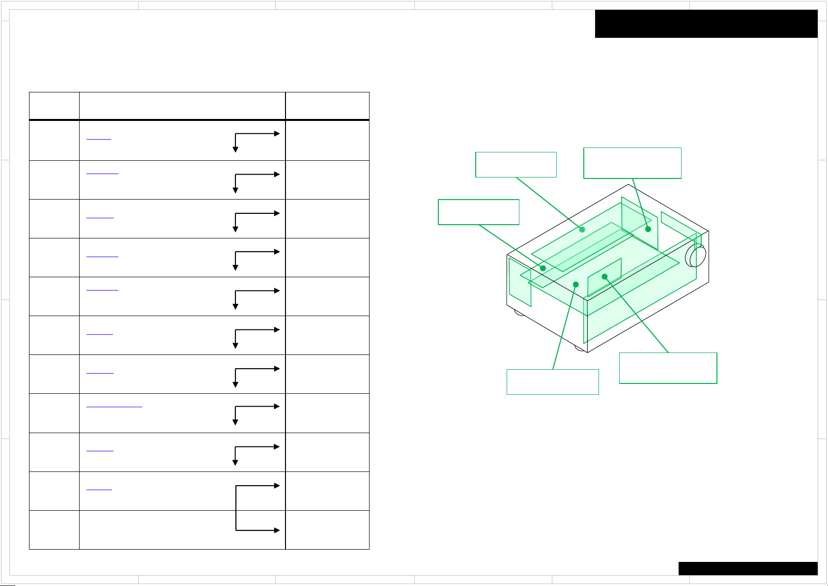
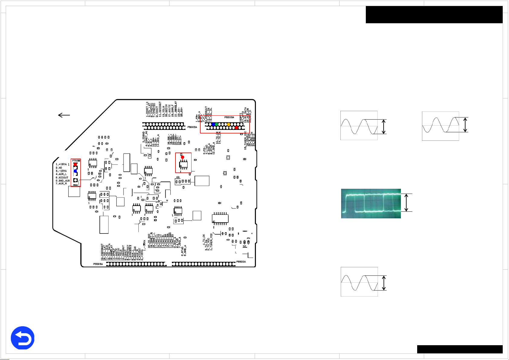
No Sound (HDMI in)
Here the trouble shoot which focuses on the hardware troubles
regarding PCB assembly is explained.
Of course, with actual repair there are also troubles due to damaged
Power Transformer, Wiring, soldering etc. in addition to PCB assembly.
D
Process Check Point Damaged PCB
1
J6718 (BAAF-1720)
● : +23V
P7003B (BADG-1742)
2
● No.1 pin : +15V
● No.3 pin : -15V
3
C
4
P801B (BAPRC-1760)
● No.5 pin : +15V
P8003A (BADG-1742)
● No.20 pin : +3.3V
P8003A (BADG-1742)
5
● No.5 pin : Check signal
● No.7 pin : Check signal
No Good
OK
No Good
OK
No Good
OK
No Good
OK
No Good
OK
このトラブルシュートは故障している基板を特定するためのものです。
ここで見つかった故障基板だけが原因ではなく、電源トランス・接続
線の結線・はんだ付けなどの不具合も考えられます
BAAF-1720
BAPRC-1760
BAAF-1720
BATRM-1754
BATRM-1754
BAPRC-1760
BAPRC-1760
Trouble Shoot
D
BADG-1742
C
6
B
7
Q1501 (BADG-1742)
● No.7 pin : Check signal
J6615 (BAAF-1720)
● : Check signal
Q6050,Q6060 (BAAF-1720)
8
● Base : Check signal
No Good
OK
No Good
OK
No Good
OK
BADG-1742
BAAF-1720
BACLA-1746
BAAF-1720
BACLA-1746
B
● Base : Check signal
9
10
A
P801B (BAPRC-1760)
● No.3 pin : +3V
P6080 (BAAF-1720)
● : Check signal
No Good
OK
No Good
OK
BAAF-1720
BAAF-1720
A
11 BATRM-1754
1
2
●Each voltage is shown as the reference value.
●各電圧は実測した標準値です
5 4 3
TX-NR545/646/747
6

1
2
5 4 3
6
No Sound (Opt in)
Here the trouble shoot which focuses on the hardware troubles
regarding PCB assembly is explained.
Of course, with actual repair there are also troubles due to damaged
Power Transformer, Wiring, soldering etc. in addition to PCB assembly.
D
Process Check Point Damaged PCB
1
J6718 (BAAF-1720)
● : +23V
P7003B (BADG-1742)
2
● No.1 pin : +15V
● No.3 pin : -15V
3
C
4
P801B (BAPRC-1760)
● No.5 pin : +15V
P8003A (BADG-1742)
● No.20 pin : +3.3V
P8003A (BADG-1742)
5
● No.15 pin : Check signal
P8003A (BADG-1742)
6
● No.5 pin : Check signal
● No.7 pin : Check signal
B
7
Q1501 (BADG-1742)
● No.7 pin : Check signal
No Good
OK
No Good
OK
No Good
OK
No Good
OK
No Good
OK
No Good
OK
No Good
OK
このトラブルシュートは故障している基板を特定するためのものです。
ここで見つかった故障基板だけが原因ではなく、電源トランス・接続
線の結線・はんだ付けなどの不具合も考えられます
BAAF-1720
BAPRC-1760
BAAF-1720
BATRM-1754
BATRM-1754
BAPRC-1760
BADG-1742
BAPRC-1760
BADG-1742
BAAF-1720
BADG-1742
BACLA-1746
Trouble Shoot
D
C
B
8
J6615 (BAAF-1720)
● : Check signal
Q6050,Q6060 (BAAF-1720)
9
● Base : Check signal
No Good
OK
No Good
OK
BAAF-1720
BACLA-1746
● Base : Check signal
10
A
11
12 BATRM-1754
P801B (BAPRC-1760)
● No.3 pin : +3V
P6080 (BAAF-1720)
● : Check signal
1
2
No Good
OK
No Good
OK
BAAF-1720
BAAF-1720
●Each voltage is shown as the reference value.
●各電圧は実測した標準値です
5 4 3
TX-NR545/646/747
A
6
1
2
5 4 3
6
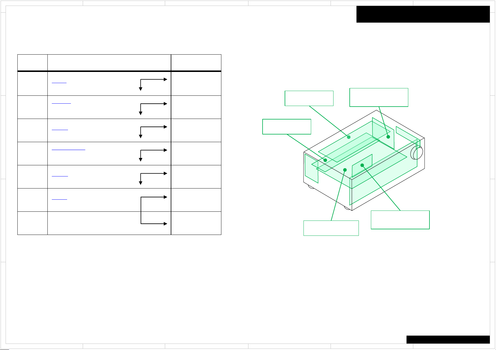
No Sound (Analog in)
Here the trouble shoot which focuses on the hardware troubles
regarding PCB assembly is explained.
Of course, with actual repair there are also troubles due to damaged
Power Transformer, Wiring, soldering etc. in addition to PCB assembly.
D
Process Check Point Damaged PCB
1
J6718 (BAAF-1720)
● : +23V
P7003B (BADG-1742)
2
● No.1 pin : +15V
● No.3 pin : -15V
3
C
J6615 (BAAF-1720)
● : Check signal
Q6050,Q6060 (BAAF-1720)
4
● Base : Check signal
● Base : Check signal
5
P801B (BAPRC-1760)
● No.3 pin : +3V
No Good
OK
No Good
OK
No Good
OK
No Good
OK
No Good
OK
このトラブルシュートは故障している基板を特定するためのものです。
ここで見つかった故障基板だけが原因ではなく、電源トランス・接続
線の結線・はんだ付けなどの不具合も考えられます
BAAF-1720
BAPRC-1760
BAAF-1720
BAAF-1720
BACLA-1746
BATRM-1754
BAAF-1720
Trouble Shoot
D
BADG-1742
C
6
B
7 BATRM-1754
P6080 (BAAF-1720)
● : Check signal
No Good
OK
BAAF-1720
BACLA-1746
B
BAAF-1720
A
1
2
●Each voltage is shown as the reference value.
●各電圧は実測した標準値です
5 4 3
TX-NR545/646/747
6
A

1
2
5 4 3
6
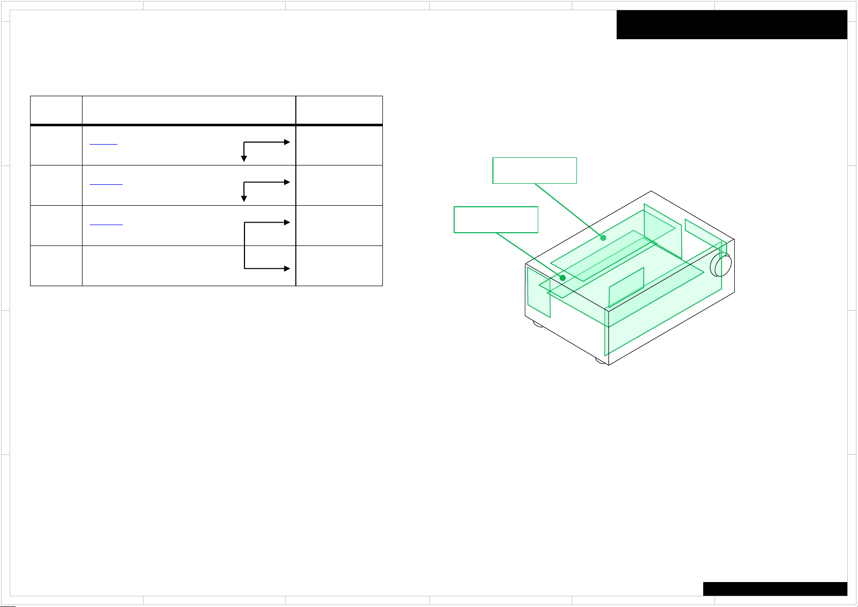
No Picture (HDMI in/ out)
Here the trouble shoot which focuses on the hardware troubles
regarding PCB assembly is explained.
Of course, with actual repair there are also troubles due to damaged
Power Transformer, Wiring, soldering etc. in addition to PCB assembly.
D
Process Check Point Damaged PCB
1
P801B (BAPRC-1760)
● No.5 pin : +15V
2 BAPRC-1760
C
No Good
OK
Trouble Shoot
このトラブルシュートは故障している基板を特定するためのものです。
ここで見つかった故障基板だけが原因ではなく、電源トランス・接続
線の結線・はんだ付けなどの不具合も考えられます
D
BATRM-1754
BAPRC-1760
BATRM-1754
C
B
A
1
2
●Each voltage is shown as the reference value.
●各電圧は実測した標準値です
5 4 3
TX-NR545/646/747
6
B
A

1
2
5 4 3
6
No Picture (Component in/ HDMI out)
Here the trouble shoot which focuses on the hardware troubles
regarding PCB assembly is explained.
Of course, with actual repair there are also troubles due to damaged
Power Transformer, Wiring, soldering etc. in addition to PCB assembly.
D
Process Check Point Damaged PCB
1
2
P801B (BAPRC-1760)
● No.5 pin : +15V
P2800B (BAPRC-1760)
● No.9 pin : +5V
P2800B (BAPRC-1760)
C
3
● No.3 pin : Check signal
● No.5 pin : Check signal
● No.7 pin : Check signal
4 BAPRC-1760
No Good
OK
No Good
OK
No Good
OK
このトラブルシュートは故障している基板を特定するためのものです。
ここで見つかった故障基板だけが原因ではなく、電源トランス・接続
線の結線・はんだ付けなどの不具合も考えられます
BATRM-1754
BAPRC-1760
BAPRC-1760
BATRM-1754
BATRM-1754
Trouble Shoot
D
C
B
A
1
2
●Each voltage is shown as the reference value.
●各電圧は実測した標準値です
5 4 3
TX-NR545/646/747
6
B
A
1
2
5 4 3
6
No Picture (Composite in/ HDMI out)
Here the trouble shoot which focuses on the hardware troubles
regarding PCB assembly is explained.
Of course, with actual repair there are also troubles due to damaged
Power Transformer, Wiring, soldering etc. in addition to PCB assembly.
D
Process Check Point Damaged PCB
1
2
3
C
P801B (BAPRC-1760)
● No.5 pin : +15V
P2800B (BAPRC-1760)
● No.9 pin : +5V
P2800B (BAPRC-1760)
● No.7 pin : Check signal
4 BAPRC-1760
No Good
OK
No Good
OK
No Good
OK
このトラブルシュートは故障している基板を特定するためのものです。
ここで見つかった故障基板だけが原因ではなく、電源トランス・接続
線の結線・はんだ付けなどの不具合も考えられます
BATRM-1754
BAPRC-1760
BAPRC-1760
BATRM-1754
BATRM-1754
Trouble Shoot
D
C
B
A
1
2
●Each voltage is shown as the reference value.
●各電圧は実測した標準値です
5 4 3
TX-NR545/646/747
6
B
A

1
2
5 4 3
6
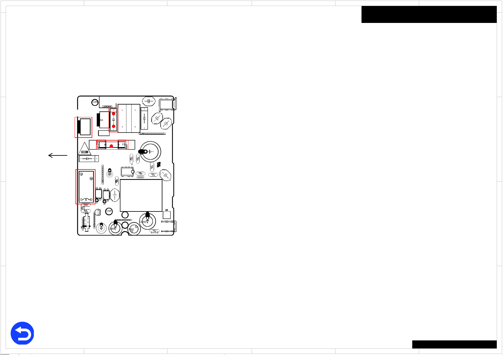
No Power
Here the trouble shoot which focuses on the hardware troubles
regarding PCB assembly is explained.
Of course, with actual repair there are also troubles due to damaged
Power Transformer, Wiring, soldering etc. in addition to PCB assembly.
D
Process Check Point Damaged PCB
1
C9001 (BAPS-1743)
● : AC100~240V
2 F9002 (BAPS-1743)
3 F6401, F6402 (BAAF-1720)
C
4 ANY PARTS (BAAF-1720)
5 P7001(FFC) (BAPRC-1760) P7001(FFC)
P9011B (BAPRC-1760)
6
● No.4 pin : +12V (StandBy)
+15V (PowerOn)
7
B
8
P9011B (BAPRC-1760)
● No.1 pin : +3V
P701A (BAPRC-1760)
● No.1 pin : +5V
No Good
OK
No Good
OK
No Good
OK
No Good
OK
No Good
OK
No Good
OK
No Good
OK
No Good
OK
このトラブルシュートは故障している基板を特定するためのものです。
ここで見つかった故障基板だけが原因ではなく、電源トランス・接続
線の結線・はんだ付けなどの不具合も考えられます
BAPS-1743
BAAF-1720
and
BACLA-1746
BAAF-1720
and
BACLA-1746
BAAF-1720
and
BACLA-1746
BAPS-1743
BATRM-1754
BAPRC-1760
BAPS-1743
BAPRC-1760
BAPRC-1760
BAAF-1720
Trouble Shoot
P7001
BADIS-1740
BACLA-1746
D
C
B
No Good
9 RL9001 (BAPS-1743)
10
P9002 (BAPS-1743)
● : AC100~240V
11 P7001(FFC) (BADIS-1740) P7001(FFC)
A
OK
No Good
OK
No Good
OK
12
1. When being not turned on with remote control unit only, BADIS-1740(TX)/ BADIS-1747(DTR) is abnormal.
2. When being not turned on with button on the main unit only, BADIS-1740(TX)/ BADIS-1747(DTR) is abnormal.
1
2
BAPS-1743
BATRM-1754
BADIS-1740
ANY PARTS on BAAF-1720 / BACLA-1740
Check damage parts
Normal(OK) or Damage (No good)
Check the damage in the red framework part as shown with visual
inspection.
e.g. Broken, Burnout, Discoloration, etc.
●Each voltage is shown as the reference value.
●各電圧は実測した標準値です
5 4 3
TX-NR545/646/747
A
6
1
R5164
R6104
R5165
R6105
R5166
R6106
J6611
J6612
C4000
J6614
C4001
J6615
J6616
R6113
R5173
R6114
R5174
R6115
R5175
R6116
R5176
L6000
L6001
C4012
L6002
C4013
L6003L6004
L6005
C4209
L6006
R6123
R5183
R6124
R5184
R6125
R5185
R6126
R5186
C4210
C4212
J4500
J4501
J4502
J4503
J4504
J4505
J4506
J4507
R5193
J4508
R5194
J4509
R5195
R5196
C4222
C4223
C4224
J4510
J4511
J4512
J4513
J4514
J4515
J4516
J4517
J4518
J4519
J4520
J4521
J4522
J4523
J4524
RL4200
J4525
J4526
J4527
RL4203
J4528
J4529
J4530
J4531
C4051
J4532
C4052
J4533
C4053
J4534
C4054
J4535
C4055
J4536
C4056
J4537
C4057
J4538
C4058
J4539
C4059
J4540
C4060
J4541
C4061
J4542
J4543
C5003
J6677
J4544
C5004
J6678
J4545
C5005
J4546
C5006
J4547
J4548
J4549
J4550
C4070
J4551
C4071
J4552
C4072
J4553
C5013
C4073
J4554
C5014
C4074
J4555
C5015
J6689
C4075
J4556
C5016
C4076
J4557
C4077
J4558
C4078
J4559
C4079
J6690
J6692
J6693
J4560
C4080
J4561
C4081
P6400A
J4562
P6400B
J4563
C5023
J4564
C5024C5025
J4566
C5026
J4567
J4568
J4569
Q4170A
J4570
J4571
P6401A
J4572
P6401B
J4573
J4574
J4575
J4576
J4577
J4578
J4579
J4580
J4581
P6402A
J4582
P6402B
J4583
C5043
J4584
C5044
J4585
C5045
J4586
C5046
J4587
J4588
J4589
P6201
J4590
J4591
J4592
J4593
C5053
J4594
C5054
J4595
C5055
J4596
C5056
J4597
J4598
J4599
R5033
R5034
R5035
R5036
Z5508
P101B
C6401
C6402
C6403
C6404
D6401A
P5502B
C5083
C5084
C5085
C5086
J6700
J6701
P5503B
J6702
J6703
J6704
J6510
J6705
J6511
J6706
J6512
C5093
J6707
J6513
C5094
J6514
J6708
C5095
J6515
C5096
J6516
P6000B
Q6033
J6517
Q6034
J6518
J6519
Q6035
Q6036
D6401
J4003
J4004
J6520
C4100
J4005
J6521
R6401
C4101
J4006
J6522
C4102
C6043
J6523
C4103
J6718
J6524
C6044
C4104
J6719
C6045
J6525
C4105
C6046
R6406
P6001B
J6526
C4106
Q6043
J6527
C4107
Q6044
J6528
C4108
J6529
Q6045
C4109
Q6046
R6023
R6024
C4300
R6025
C4301
R6026
C4302
J6530
C6050
C6051
J6531
J6532
C6052
J6533
C6053
C4307
J6534
Q6050
C6054
C4308
Q6051
J6535
C6055
P6002B
Q6052
J6536
C6056
J6537
Q6053
J6538
Q6054
J6539
Q6055Q6056
R5093
R5094
C6250
R5095
C6251
C4311
R5096
C6252
C6253
J4600
P6080
J6540
C6254
C4314
J4601
C4315
P6081
J6541
C6255
J4602
J6542
P6082
C6256
J4603
J6543
P6083
J4604
Q6060
J6544
P6084
C4318
P6003A
J4605
C4319
Q6061
P6085
J4606
Q6062
J6546
P6086
J4607
J6547
Q6063
J4608
J6548
Q6064
J4609
J6549
Q6065
C6451
Q6066
R6043
C6453
R6044R6045
C6455
R6046
C6456
J4610
J6550
C4130
D4300
J4611
J6551
D4301
J4612
J6552
D4302
J4613
J6553
D4303
J4614
J6554
D4304
J4615
D4305
J4616
J4617
J4618
J6558
J4619
J6559
RL6430
J4620
J6560
P6600A
J4621
J6561
J4622
J6562
J4623
J6563
J4624
J6564
J4625
J6565
J4626
J6566
J4627
J6567
J4628
C4530
J4629
C4531
R6640
C4534
R6641
C4535
R6642
C4536
R6643
C4537
RL6440
J4630
J6570
R6644
J4631
J6571
R6645
J4632
R6646
J6572
J4633
J6573
J4634
J6574
J4635
J4636
J4637
J4638
J4639
R6073
R6074
C4544
R6075
C4545
R6076
C4546
C4547
J4640
P5508
J4641
J4642
J4643
C5103
J4644
C5104
J4645
C5105
J6586
C5106
C4166
J4647
C4167
J4648
R6080
C4550
J4649
R6081
C4551
R6082
R6083R6084
Z10
R6085
R6086
J4650
C4170
J4651
C4171
J4652
C4172
J4653
C5113
C4173
J4654
C5114
Q4170
C4174
J4655
C5115
Q4171
C4175
J4656
C4176
C5116
J4657
C4177
J4658
R6090
J4659
R6091R6092R6093R6094R6095
R6096
J4661
F6401A
J4662
F6401B
J4663
J4664
C4184
J4665
C4185
J4666
C4186
C4187
R4160
R4161
R4162
R4163
Z33
F6402A
F6402B
Z38
Z39
J4484
R4170
J4485
R4171 R4172R4173
R4174
R4175
R4176
R4177
P6103
P6104
Z49
P6107
R5123
R5124
R5125
R5126
R5133
R5134R5135
R5136
R4197
R4198
J6006
Z66
RU11
P4002P4003
P4004
P4007
P4008
P4009
J6021
Z1
J6602
Z4
P4011
Z6
R6100
Z8
R6101
R6102
R5163
R6103
J4565
J4646
P4001
F6403A
F6403B
F6404A
F6404B
J4667
P5506B
P5509A
P6009B
Z11
Z13Z14Z15
Z23
Z24
2
5 4 3
6
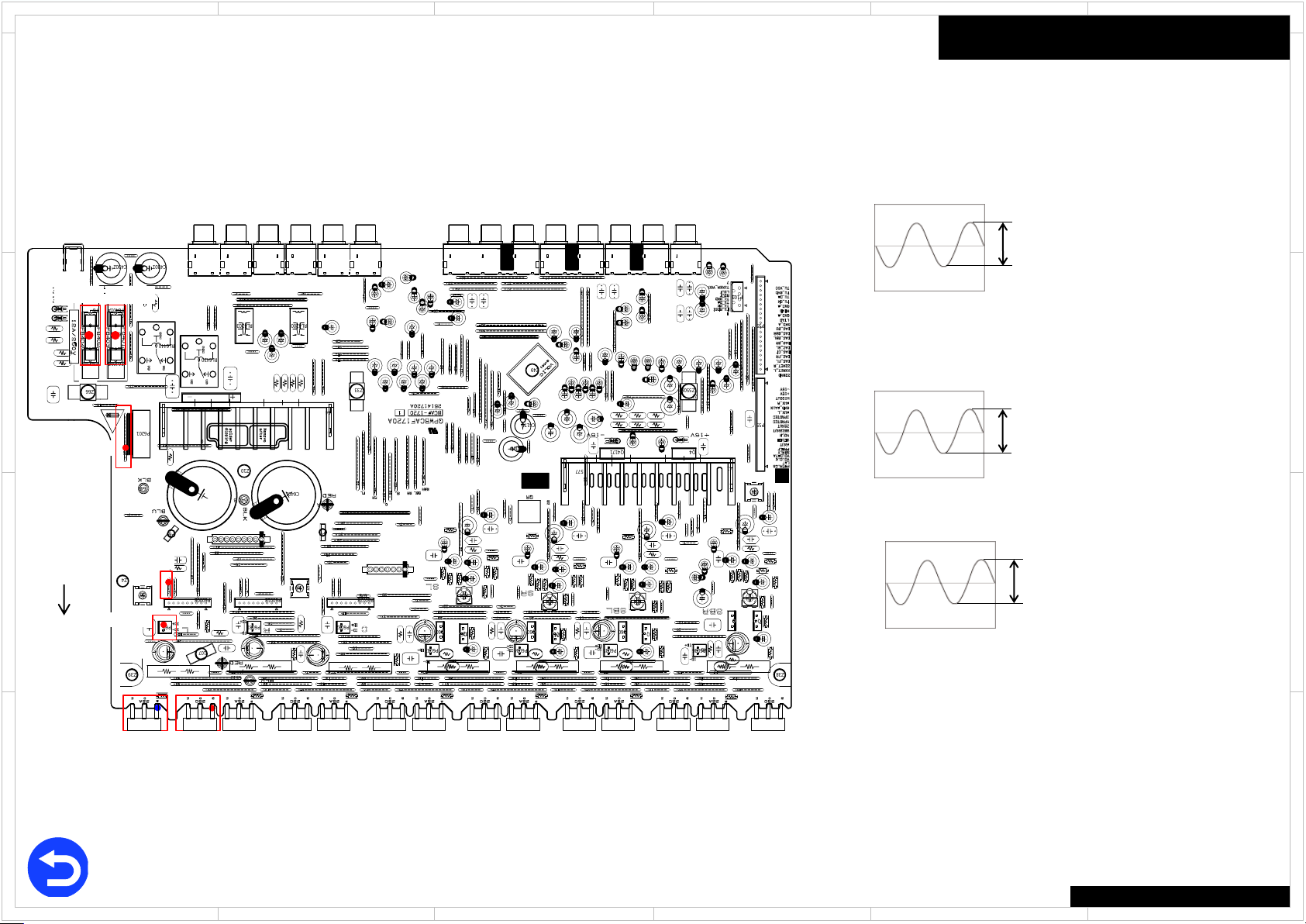
Check Point (BAAF-1720)
D
F6402
C
B
Front
A
J6718
F6401
P6080
Q6050
Back
1
J6615
Q6060
J6615, Q6050, Q6060, P6080
Input terminal : HDMI IN or OPT IN or ANALOG IN
Input signal(HDMI/OPT IN) : Test disc 1kHz 0dB
Audio format : LPCM, Dolby Digital(Otherwise, CD)
Input signal(ANALOG IN) : 1kHz 2Vrms
Master volume : 46
2
Trouble Shoot
J6718
Check voltage
● : ca. +23V
J6615
Check signal
ca. 100mV
Q6050, Q6060
Check signal
● Q6050(base) :
● Q6060(base) :
P6080
Check signal
F6401
Check damage
● Normal (OK) or blown (No good)
F6402
Check damage
● Normal (OK) or blown (No good)
●Each voltage is shown as the reference value.
●各電圧は実測した標準値です
ca. 3.3V
ca. 1.5V
TX-NR545/646/747
5 4 3
6
D
C
B
A
1
Q1501
Q1502
Q1503
Q1504
C1513
C1514
C1515
C1516
C1523
C1524
C1525
C1526
R1500
R1501
R1502
R1503
R1504
L1000
R1505
R1506
R1507
L1003
L1005
R1510
R1511
R1512
R1513
R1514
R1515
R1516
R1517
R1520
R1521
R1522
R1523
R1524
R1525
R1526
R1527
R1530
R1531
R1532
R1533
R1534
R1535
R1536
R1537
R1540
R1541
R1542
R1543
R1544
R1545
R1546
R1547
R1550
R1551
R1552
R1553
R1554
R1555
R1556
R1557
C1582
C1583
R1560
R1561
R1562
R1563
R1564
R1565
R1566
R1567
R1570
R1571
R1572
R1573
R1574
R1575
R1576
R1577
R1580
R1581
R1590
R1591
R1598
R1599
C1000
C1001
C1002
C1003
Q1000
C1005
C1009
C1010
C1011
C1012
C1014
C1015
Q1401
D1000D1001
R1000
R1001
R1002R1003
R1004
Q1411
R1005
R1011
R1012
Q1421
R1400
R1401
R1402
R1403
C1620
C1621
R1021
R1410
R1411
R1420
R1421
R1624
R1430
R1431
R1440
R1441
R1450
R1451
R1460
R1461
R1470
R1471
R1480
R1481
2
5 4 3
6
Check Point (BADG-1742)
D
Front
C
P7003B
B
A
Back
1
2
Q1501
Trouble Shoot
P7003B
Check voltage
● No.1 pin : +15V
● No.3 pin : -15V
P8003A
Check voltage
● No.20 pin : +3.3V
P8003A
Check voltage
● No.5 pin : Check signal ● No.7 pin : Check signal
P8003A
3V
3V
Input terminal : HDMI IN or OPT IN
Input signal(HDMI/ OPT IN) : Test disc 1kHz 0dB
Audio format : LPCM, Dolby Digital(Otherwise, CD)
P8003A
Check voltage
● No.15 pin : Check signal
3.3V
Input terminal : HDMI IN or OPT IN
Input signal(HDMI/ OPT IN) : Test disc 1kHz 0dB
Audio format : LPCM, Dolby Digital(Otherwise, CD)
Q1501
Check voltage
● No.7 pin : Check signal
5.6V
Input terminal : HDMI IN or OPT IN
Input signal(HDMI/ OPT IN) : Test disc 1kHz 0dB
Audio format : LPCM, Dolby Digital(Otherwise, CD)
●Each voltage is shown as the reference value.
●各電圧は実測した標準値です
TX-NR545/646/747
5 4 3
6
D
C
B
A

1
R8238
R3418
R8044
L8310
R3419
R8045
R3226
R8046
R3033
R3034
C3445
C3446
C3447
R8240
R3420
L8700
P8671
R3421
R3039
C8651
L3112
R8243
L8703
R3424
R3230
R8244
D8248
L8704
R3425
P8701A
L8705
R3234
R3428
R3429
R3043
R3239
R3046
R3430
L8710
R3048
C3070
R3049
C3071
C8661
R3432
R3240
Q3070
R8060
R3435
R3241
R8061
Q3071
R3436
R8062
R3437
R8063
R3438
R3244
R3050
R8064
R3051
R8065
C3462
R8066
R3054
C8091
R3056
R1117
R3441
C8095
R3442
C8096
R3443
C8097
C8098
R3445
L1001
R8072
R3447
R3448
L1004
L1005
1
L1006
L1007
R3257
R8077
R3064
R8078
X7001
L1009
R3065
R8079
R3450
R3068
R3069
R3452
R3453
L8157
R3454
L1010
R3260
R8080
R3455
L1011
R8081
R3456
L1012
R8082
R3457
L1013
R8083
R3458
R8084
R3459
R3266
L8931
P7050A
L8932
L8933
R3460
L8934
R3463
R3270
P751A
R3272
R3467
R3274
R3276
R8097
R8098
L8941
R8099
L8942
L8943L8944
R7101
P752A
R7103
R3283
R7105
R3285R3286
L8951
L8952
L8953L8954
R3481
P501B
R3484R3485
R7114
R7116
R3297
L8961
L8962
L8963
P8104
L8964
R3494R3495
R3496
R7122
R3497
R7123
R7124
R7125
R7126
P9011B
P3104
R7132
R7133
R7134
R7135
R7136R7137
P8702
P8703
C8108
R7141
X8201
Q8302
C8113
P8710
X3001
C3101
C3102
C3103
Q8114
R7150
R7151
Q8115
Q3105
Q3106
Q3108
C8700
C3113
C3114
R8100
Q8701
C8705
C3115
R8101
Q3306
C3116
Q8702
C3117
Q3113
Q8703
Q3308
X3401
R8105
C3119
C8321
Q3115
R8106R8107
C8325
R8109
X8031
C8903
R8300
C8904
C8710
C3120
R8301
Q8901
C8905
C8711
R8302
C8906
C8712
C8907
C8713
C8908
Q8710
Q3120
R8110
C8714
R8111
Q8711
D3101
C8715
D3102
R8112
C8716
D3103
C8717
R8114
C8718
Q8714
R3101
C8719
C8911
L8000
C3324
C8914
L8001
C3325
Q8911
L8002L8003
R8313
C8917
C1000
L8004
CAM28
C1001
R8315
L8006
R8316
C1003
R8317
R8318
C1005
R8701
Q1001
R8319
R8702
C1007
R7187
R8703
R7188
C1008
R8704
R8705
Q1005
C1009
C8346
R3500
R8320
R8708
R3501
R8321
R8709
R3502
D8902
R8322
R3503
D8903
R8323
C3143
R3504
D8904
R8324
R3505
R8901
L3001
R8325
R8902
L3002
D8906
C1012
R8326
L3003
D8907
R8327
R8903
R3508
C1014
R8328
D8908
R8710
R3509
R8329
D8909
R8711
R8906
R8712
R8907
R8713
C1017
R8908
C1018
R8714
R8909
C1019
C8931
R8715
R8139
C8932
C8933
R8718
R3128
R8330
C8934
R8719
R8331
Q8931
C8935
L8021
R8332
C8936
Q8932
L8022L8023
R8333
C8937
L8024
R8910
C1020
C8938
R8140
C8168
R8911
C1021
R8141
C8169
R8335
L8025
R8912
C1022
R8142
R8336
L8026
R8913
C1023
R8143
R8720
C1024
C1025
R8145
R8721
C1026
R3132
R8146
R8723
C1027
R3133
C1028
R3134
R8148
R8919
C1029
C8941
R8149
R3136
C8942
R8726
L3403
C8943
R8727
L3404
R8728
C8944
C8369
L3405
R3139
Q8941
C8945
R8729
L3406
R1006
R8342
C8946
Q8942
R1007
R8343
C8947
L3408
R8920
R1008
C8948
R8150
C1031
L3409
R8921
CAM59
R8151
R8346
R8152
R8153
R8730
P3102A
R8155
R8732
R3143
R8734
R3144
R3145
C8951
R8735
C8952
R8737
C8953
C8954
Q8951
C8955
C8956
Q8952
C3172
R1017
C8957
C3173
C8958
R1019
R8931R8932
R8933
R8934
R3150
R8935
R8359
P3103A
R8936
R8937
R1020
R3154
R8744
R1021
C8961
C8385
R1022
C8962
R8746
R8747
R3157
C8963
R1024
C8964
P701A
R1025
Q8961
C8965
C7002
R1026
C8966
C8967
R8363
C8968
R8364
C7005
R8941
R8365
C7006
R8366
R8943
R8367
R8944
R8368
R8945
R8946
R3162
R8947
R8753
R3163
R8754
C1058
Q7009
R1031
R8755
C1059
R1032
R8756
R8757
R1034
R3168
R8370
R1035
R3169
R1036
R1037
R1038
R8374
C7015
R1039
R8952
C7017
R8953
R8954
R8955
R8956
Q7017
R8957
R3173
R1040
R3174
C8980
R1041
R1042
C8982
R3176
R3177
R1043
C7020
R1044
C8984
R3178
R1046
R1047R1048
D8964
11
P801
R8961
R1049
D8965
12
D7002
R8962
D8966
C1073
D7003
R8963
D7004
R8964
C1075
D7005
R8965
R3181
15
R8966
R3182
D7007
R8967
R3183
R3184
R7005
D7009
19
R8776
R7006
R7008
C7030
R3188
R7009
D7010
D7011
R7010
R3190
R7013
R1060
R1061
P8002B
R1062
R7017
R1063
R1064
R7018R7019
P8001
R8982R8983
R8790
R7020
R8791
R7021
R7025
R8795
R7026
P8003B
R7027
R7028
110
R8798
R7029
P2800B
P3002
R7030
R7031
R7032
R7033
R7034
121
P8021
P801B
P8601
Q8003
R7042
P3401
R7048
Q8202
C8206C8207
C8208
C3001
P8611
C3002
C3003
C8018
C3004
X8301
Q3001
C3005
R7051
C3006
R7052
Q3003
C3007
R7053
Q3004
C3008
C8210
C3009
C8211
R7056
C8020
C8021
C8219
P8621
C3012C3013
P3610
R8000
R7060
D8004
R8001
C3015
R7061
R8002
C3016
R7062
C3017
R7063
C3018
C8220
R7064
C3401
C8221
R7065
R7066
C8223
C8224
X3110
X8701
C8225
R7069
Q3404
C3020
P8631
C8612
C3023
R8204
R7070
C8038
Q3408
C3025
R7071
Q3409
Q8035
C3027
R8208
C3028
R8209
R8015
C3029
C8231
R7075
C3412
C8232
C3413
R8017
C3414
Q3410
R3004
C3415
R7079
R3006
C8236
C8237
R3008
C3419
R3009
C3031
C8239
P8641
C3032
C8622
C3033
C3034
R3200
R8215
C3035
R7081
R8021
C3036
R8022
C3037
R8023
R8218
C3038
C8240
R7084
R8024
R3011
C8241
C3422
C3423
R8603
R8027
R3207
R3208
R8604
C3424
R8028
C3425
R8605
D3401
D3402
R3016
R3017
R3400
R8220R8221
X1001
C8631
P8651
X1002
R8223
C3043
R8030
R3210
R8225
R7091
R8031
R8226
R3212
R7092
R8032
R7093
R3213
R3408
R8228
R7094
R3409
R3215
R7095
R3022
R7097
R7098
C3435
R7099
C8061
R8039
C3436
R3028
R3410
L8309
P8661
R3411
R3412
L3102
C8642
L3105
R3221
R3415
R8041
R3416
R8237
R3417
R8043
Q3072
120
122
Q8000
P3100
D8700
D8931D8941D8951D8961
D8963
R8800
D8708
D8709
C3183
2
5 4 3
6
Check Point (BAPRC-1760)
D
C
B
A
Back
1
P9011B
Trouble Shoot
P801B
Check voltage
● No.5 pin : ca. +12V (Stand By), ca. +15V (Power On)
P801B
Check voltage
● No.3 pin : ca. +3V
P2800B
Check voltage
● No.9 pin : ca. +5V
P2800B
Check signal
● No.3 pin : signal ● No.5 pin : signal
64μS
ca. 1.4V
64μS
Input signal : Color bar(NTSC) ● No.7 pin : signal
64μS
ca. 2.2V
P7001(FFC)
P801B
P2800B
P701A
● Check damage and connection
How to check
1.Disconnect the FFC from the socket.
2.Check the contacts of the FFC.
Front
FFC
P7001
2
P9011B
Check voltage
● No.4 pin : ca. +12V (Stand By), ca. +15V (Power On)
P9011B
Check voltage
● No.1 pin : ca. +3V
P701A
Check voltage
● No.1 pin : ca. +5.2V
●Each voltage is shown as the reference value.
●各電圧は実測した標準値です
5 4 3
TX-NR545/646/747
6
ca. 1.4V
D
C
B
A
1
C9010
C9012
C9013
C9018
C9019
C9020
C9025
R9001
R9010
R9011
R9014
R9015
R9016
R9019
R9021
R9027
R9030
R9031
F9001
T9001
F9002A
P9011A
F9002B F9002CF9002D
J9001
J9002
J9003
J9004
J9005
J9011
J9030
CAM82
CAM83
CAM84
L9001
CAM85
CAM86
L9002
P9001A
P9002
P9003
P9004
C9001
C9002
C9003
C9004
Q9001
Q9002
C9006
Q9003
C9007
Q9004
2
5 4 3
6
Check Point (BAPS-1743)
D
P9002
C
Front
RL9001
C9001
F9002
Trouble Shoot
C9001
Check voltage
● : AC100 ~ 240V (Power supply voltage)
F9002
Check damage
● Normal (OK) or blown (No good)
RL9001
Check operation of a relay by sound.
No sound at all ---> No good
P9002
Check voltage
● : AC100 ~ 240V (Power supply voltage)
D
C
B
A
Back
1
B
A
●Each voltage is shown as the reference value.
●各電圧は実測した標準値です
2
5 4 3
TX-NR545/646/747
6
1
CAM64
P7702
Q7502
C7508
J7600
C7513
C7515
C7518
C7533
C7541
Q7541
S7502
C7552
C7561
C7562
C7950
C7960
C7961
CAM11
C7962
CAM12
C7963
CAM15
CAM16
CAM17
CAM19
CAM21
CAM22
R7951R7952 R7953
D7960
D7961
R7960
R7961
P7001B
P7802
J7501
J7502
J7503
J7504
J7505
J7506
J7507
J7508
P7003A
J7509
J7510J7511
J7512J7513
C7803
J7514J7515
C7805
J7516J7517
J7518
CAM1
J7519
CAM4
CAM5
P9501B
J7520
CAM8
J7521
C7811
CAM9
J7522
C7812
J7523J7524J7525J7526J7527
J7528
J7529
J7530
J7531
J7532
J7533
J7534
J7535
J7536
J7537
J7538J7539
J7540
J7541
C7831
J7542
J7543
J7544
J7545
J7546
J7547
J7548
J7549
J7550
S7600
S7601
J7551
J7552
J7553
J7554
S7605
J7555
S7606
J7556
J7557
S7607
J7558
S7608S7609
J7559
S7610
J7560
J7561
S7611
J7562
S7612S7613
J7563
J7564
S7614
J7565
S7615
J7566
S7616
J7567
S7617
J7568
S7618
J7569
S7619
S7620
J7570
J7571
S7621
J7572
S7622
J7573
S7623
J7574
S7624
J7575
S7625 S7626
J7576
J7577
S7627 S7628
J7578
S7629
J7579
D7652
D7653
D7654
D7656
J7580
S7630S7631
J7581
J7582
S7632
J7583J7584
J7585
J7586
S7636
J7587
S7637
J7588
S7638
J7589
J7590
J7591
J7592
J7593
J7594
J7595
J7596
J7597
J7598
J7599
2
5 4 3
6
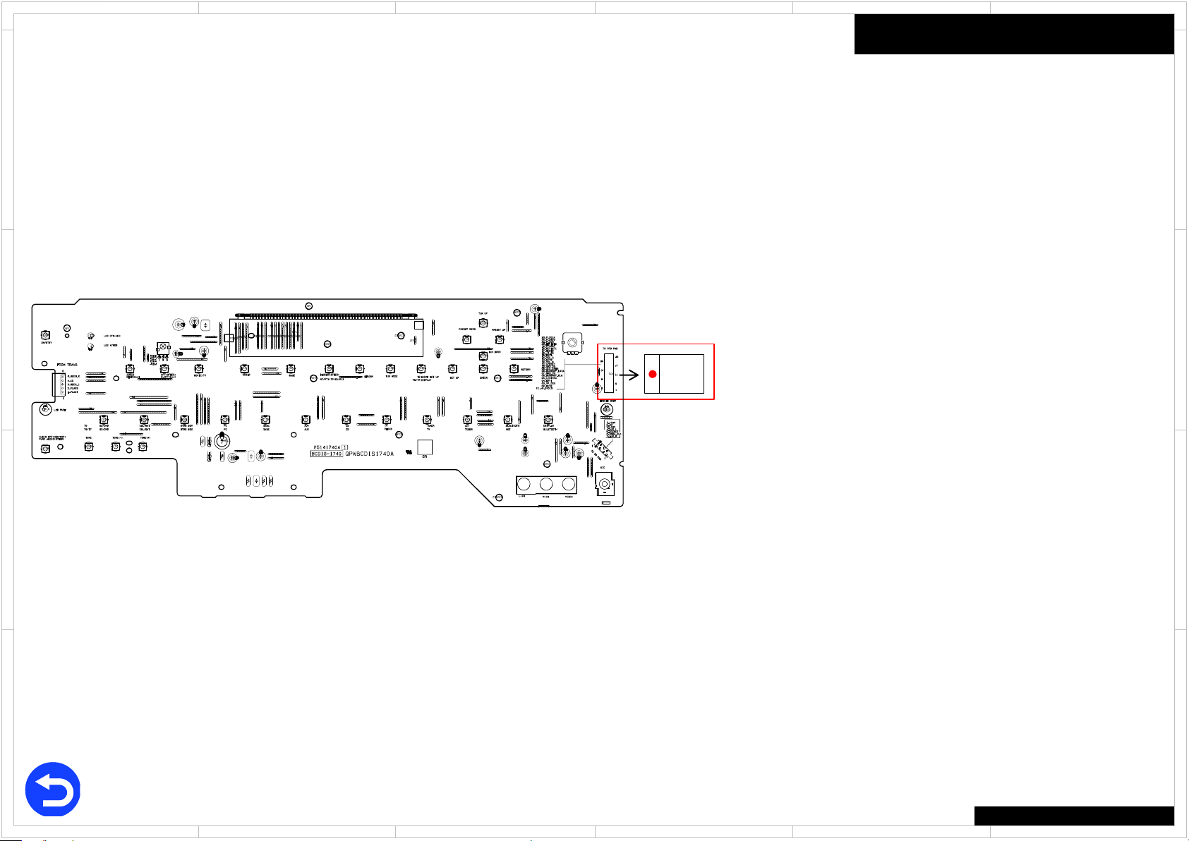
Check Point (BADIS-1740)
D
C
FFC
P7001
Trouble Shoot
P7001
● Check damage and connection
How to check
1.Disconnect the FFC from the socket.
2.Check the contacts of the FFC.
D
C
B
A
Back
1
2
●Each voltage is shown as the reference value.
●各電圧は実測した標準値です
5 4 3
TX-NR545/646/747
6
B
A
1
2
5 4 3
6
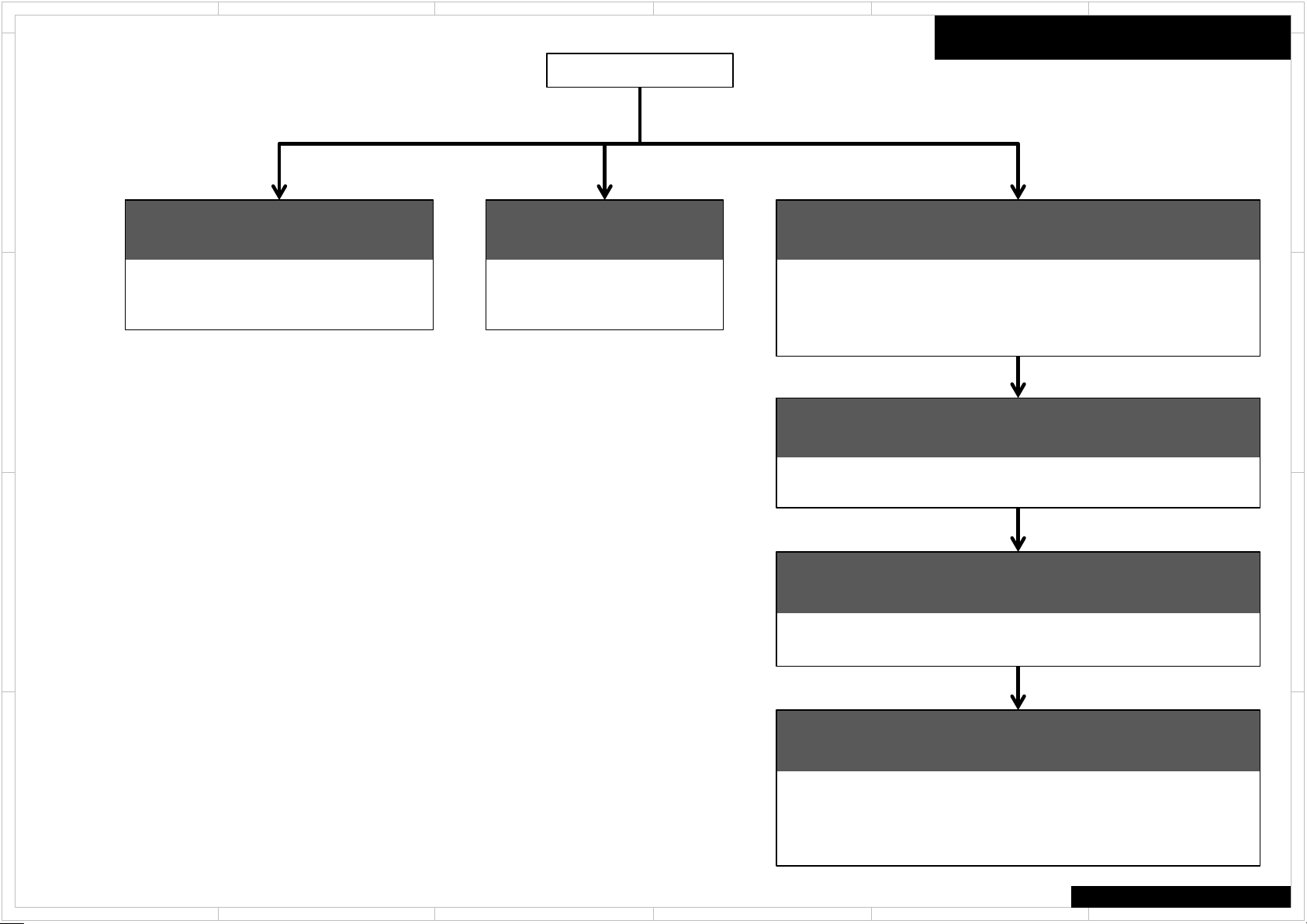
Overview
This model can be disassembled in the order shown below.
D
FRONT PANEL
Refer to 「Front Panel Section」
PCB BADIS-1740
PCB BAETC-1745
PCB BAHDM-1770
C
TOP COVER
FAN
Refer to 「FAN Section」
FAN (Except TX-NR545)
Disassembly
D
PROCESSOR & WIFI PCB
Refer to 「Processor & WiFi Section」
PCB BAPRC-1760
PCB BARF-1771 : TX-NR646/747
PCB BARF-1567 : TX-NR545
PCB WiFi & Bluetooth Comb Module
C
VIDEO & TUNER PCB
Refer to 「Video & Tuner Section」
PCB BATRM-1754
PCB BARF-1731
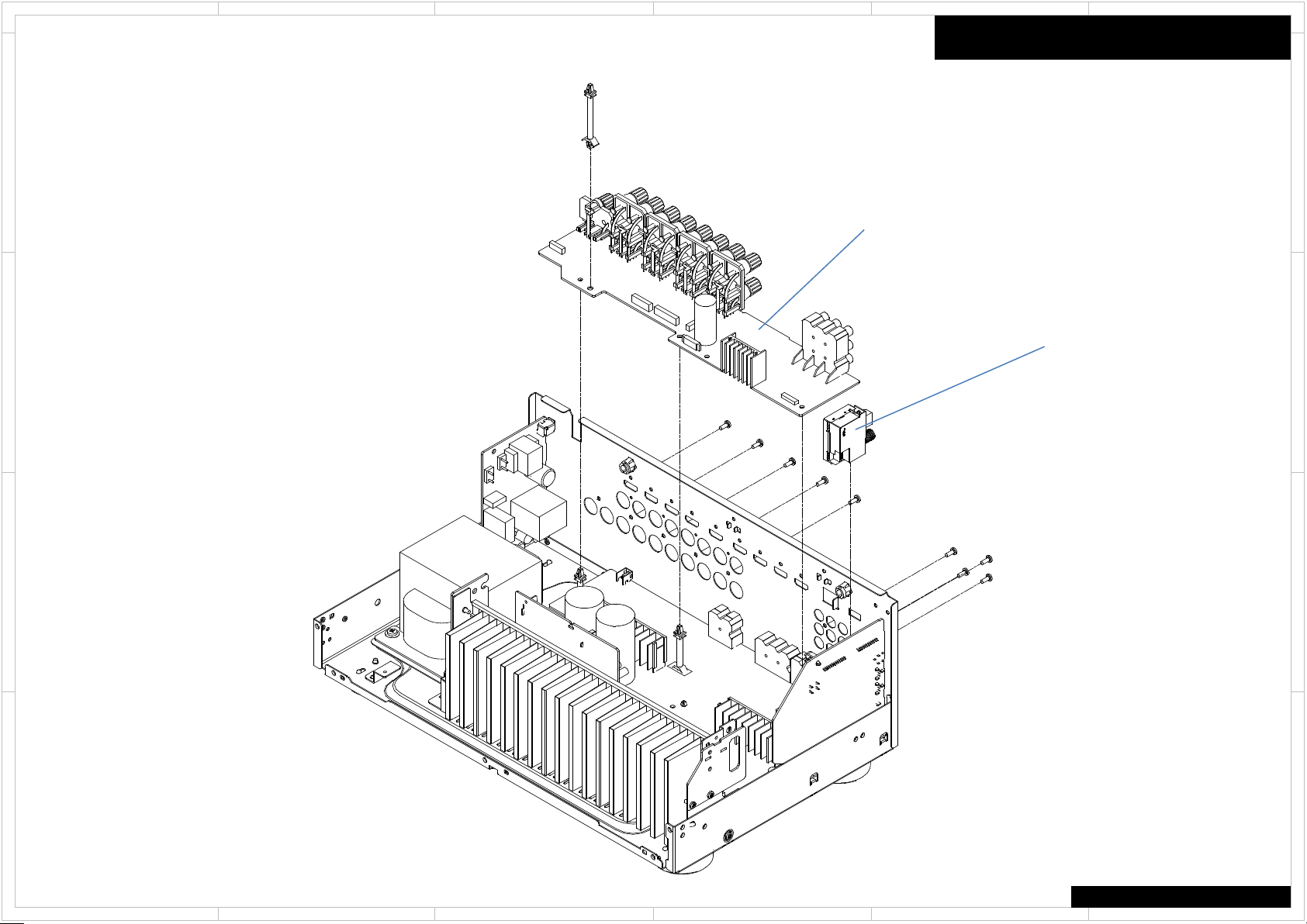
POWER SUPPLY & DIGITAL PCB
B
Refer to 「PowerSupply & Digital Section 」
B
PCB BAPS-1743
PCB BADG-1742
AMPLIFIER PCB
Refer to 「Amplifier Section 」
PCB BAAF-1720
A
PCB BACLA-1746
A
Q6050~6056 / Q6060~Q6066
TX-NR545/646/747
1
2
5 4 3
6

1
2
5 4 3
6
Front Panel Section
This is TX-NR646. TX-NR545/747 is same mostly structurally. Please refer to PANEL pages for detailed place by the terminal.
D
Except TX-NR545
BADIS-1740
BAETC-1745
BAHDM-1770(Except TX-NR545)
C
Disassembly
D
C
B
A
B
A
TX-NR545/646/747
1
2
5 4 3
6
1
2
5 4 3
6
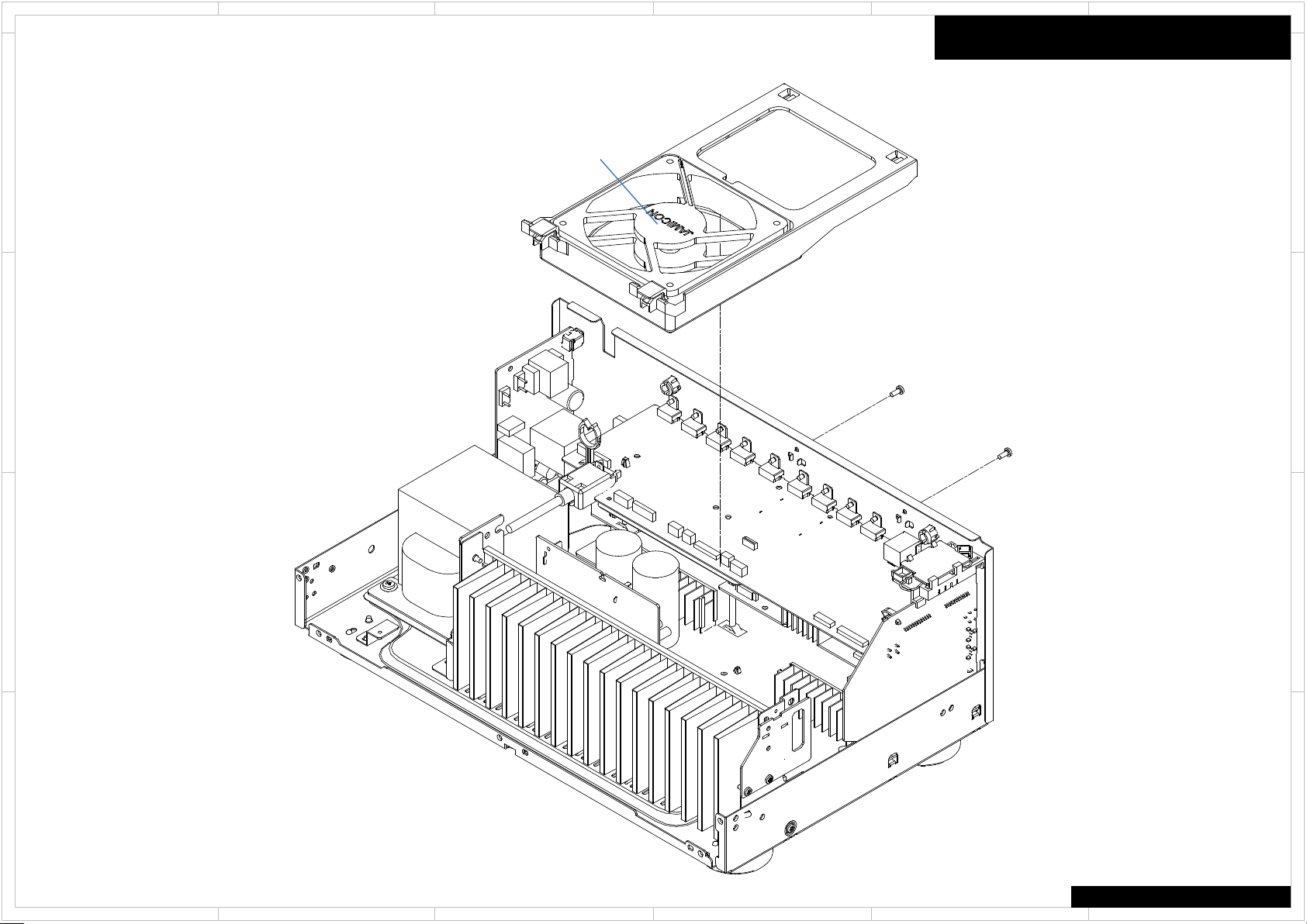
FAN Section
This is TX-NR646. TX-NR545/747 is same mostly structurally. Please refer to PANEL pages for detailed place by the terminal.
FAN
D
C
(Except TX-NR545)
Disassembly
D
C
B
A
B
A
TX-NR545/646/747
1
2
5 4 3
6
1
2
5 4 3
6
Processor & WiFi Section
This is TX-NR646. TX-NR545/747 is same mostly structurally. Please refer to PANEL pages for detailed place by the terminal.
D
Except TX-NR545
C
Disassembly
D
BAPRC-1760
C
BARF-1771 : TX-NR646/747
BARF-1567 : TX-NR545
B
B
WIFI BT COMB MODULE
A
A
TX-NR545/646/747
1
2
5 4 3
6
1
2
5 4 3
6
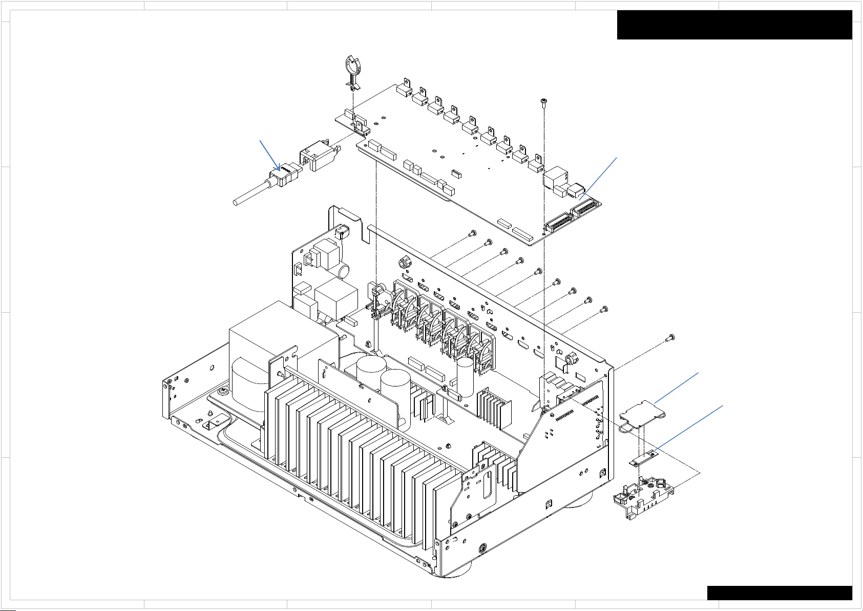
Video & Tuner Section
This is TX-NR646. TX-NR545/747 is same mostly structurally. Please refer to PANEL pages for detailed place by the terminal.
D
C
Disassembly
D
BATRM-1754
BARF-1731
+ SHLD CASE (TUNER-TOP & BOTTOM)
C
B
A
B
A
TX-NR545/646/747
1
2
5 4 3
6
Loading...