


AV Receiver
TX-L5
Instruction Manual
Thank you for purchasing the Onkyo AV Receiver. Please read this manual thoroughly before making connections and turning on the power.
Following the instructions in this manual will enable you to obtain optimum performance and listening enjoyment from your new AV Receiver.
Please retain this manual for future reference.
Contents
Before Using Your AV Receiver 2
Getting started
Turning on the AV Receiver/ Speaker Setup
Enjoying music or videos
Enjoying Surround mode/ Recording
Other
WARNING:
TO REDUCE THE RISK OF FIRE OR ELECTRIC SHOCK, DO NOT EXPOSE THIS APPLIANCE TO RAIN OR MOISTURE.
CAUTION:
TO REDUCE THE RISK OF ELECTRIC SHOCK, DO NOT REMOVE COVER (OR BACK).
NO USER-SERVICEABLE PARTS INSIDE. REFER SERVICING TO QUALIFIED SERVICE PERSONNEL.
WARNING
RISK OF ELECTRIC SHOCK
DO NOT OPEN
AVIS
RISQUE DE CHOC ELECTRIQUE
NE PAS OUVRIR
The lightning flash with arrowhead symbol, within an equilateral triangle, is intended to alert the user to the presence of uninsulated “dangerous voltage” within the product’s enclosure that may be of sufficient magnitude to constitute a risk of electric shock to persons.
The exclamation point within an equilateral triangle is intended to alert the user to the presence of important operating and maintenance (servicing) instructions in the literature accompanying the appliance.
Important Safeguards
1.Read Instructions – All the safety and operating instructions should be read before the appliance is operated.
2.Retain Instructions – The safety and operating instructions should be retained for future reference.
3.Heed Warnings – All warnings on the appliance and in the operating instructions should be adhered to.
4.Follow Instructions – All operating and use instructions should be followed.
5.Cleaning – Unplug the appliance from the wall outlet before cleaning. The appliance should be cleaned only as recommended by the manufacturer.
6.Attachments – Do not use attachments not recommended by the appliance manufacturer as they may cause hazards.
7.Water and Moisture – Do not use the appliance near water –for example, near a bath tub, wash bowl, kitchen sink, or laundry tub; in a wet basement; or near a swimming pool; and the like.
8.Accessories – Do not place the appliance on an unstable cart, stand, tripod, bracket, or table. The appliance may fall, causing serious injury to a child or adult, and serious damage to the appliance. Use only with a cart, stand, tripod, bracket, or table recommended by the manufacturer, or sold with the appliance.
Any mounting of the appliance should follow the manufacturer’s instructions, and should use a mounting accessory recommended by the manufacturer.
9. An appliance and cart combination |
PORTABLE CART WARNING |
|
should be moved with care. Quick |
||
|
||
stops, excessive force, and uneven |
|
|
surfaces may cause the appliance |
|
|
and cart combination to overturn. |
|
|
10.Ventilation – Slots and openings in |
|
|
the cabinet are provided for |
S3125A |
ventilation and to ensure reliable  operation of the appliance and to protect it from overheating, and these openings must not be blocked or covered. The openings should never be blocked by placing the appliance on a bed, sofa, rug, or other similar surface. The appliance should not be placed in a built-in installation such as a bookcase or rack unless proper ventilation is provided. There should be free space of at least 20 cm (8 in.) and an opening behind the appliance.
11.Power Sources – The appliance should be operated only from the type of power source indicated on the marking label. If you are not sure of the type of power supply to your home, consult your appliance dealer or local power company.
12.Grounding or Polarization – The appliance may be equipped with a polarized alternating current line plug (a plug having one blade wider than the other). This plug will fit into the power outlet only one way. This is a safety feature. If you are unable to insert the plug fully into the outlet, try reversing the plug. If the plug should still fail to fit, contact your electrician to replace your obsolete outlet. Do not defeat the safety purpose of the polarized plug.
13.Power-Cord Protection – Power-supply cords should be routed so that they are not likely to be walked on or pinched by items placed upon or against them, paying particular attention to cords at plugs, convenience receptacles, and the point where they exit from the appliance.
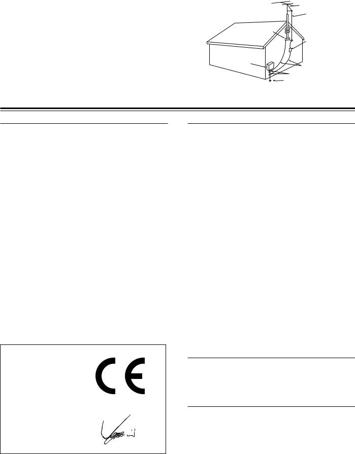
14.Outdoor Antenna Grounding – If an outside antenna or cable system is connected to the appliance, be sure the antenna or cable system is grounded so as to provide some protection against voltage surges and built-up static charges. Article 810 of the National Electrical Code, ANSI/NFPA 70, provides information with regard to proper grounding of the mast and supporting structure, grounding of the lead-in wire to an antenna-discharge unit, size of grounding conductors, location of antenna-discharge unit, connection to grounding electrodes, and requirements for the grounding electrode. See Figure 1.
15.Lightning – For added protection for the appliance during a lightning storm, or when it is left unattended and unused for long periods of time, unplug it from the wall outlet and disconnect the antenna or cable system. This will prevent damage to the appliance due to lightning and power-line surges.
16.Power Lines – An outside antenna system should not be located in the vicinity of overhead power lines or other electric light or power circuits, or where it can fall into such power lines or circuits. When installing an outside antenna system, extreme care should be taken to keep from touching such power lines or circuits as contact with them might be fatal.
17.Overloading – Do not overload wall outlets, extension cords, or integral convenience receptacles as this can result in a risk of fire or electric shock.
18.Object and Liquid Entry – Never push objects of any kind into the appliance through openings as they may touch dangerous voltage points or short-out parts that could result in a fire or electric shock. Never spill liquid of any kind on the appliance. 19.Servicing – Do not attempt to service the appliance yourself as opening or removing covers may expose you to dangerous
voltage or other hazards. Refer all servicing to qualified service personnel.
20.Damage Requiring Service – Unplug the appliance form the wall outlet and refer servicing to qualified service personnel under the following conditions:
A.When the power-supply cord or plug is damaged,
B.If liquid has been spilled, or objects have fallen into the appliance,
C.If the appliance has been exposed to rain or water,
D.If the appliance does not operate normally by following the operating instructions. Adjust only those controls that are covered by the operating instructions as an improper adjustment of other controls may result in damage and will often require extensive work by a qualified technician to restore the appliance to its normal operation,
E.If the appliance has been dropped or damaged in any way, and
F.When the appliance exhibits a distinct change in performance
– this indicates a need for service.
2
21.Replacement Parts – When replacement parts are required, be sure the service technician has used replacement parts specified by the manufacturer or have the same characteristics as the original part. Unauthorized substitutions may result in fire, electric shock, or other hazards.
22.Safety Check – Upon completion of any service or repairs to the appliance, ask the service technician to perform safety checks to determine that the appliance is in proper operation condition.
23.Wall or Ceiling Mounting – The appliance should be mounted to a wall or ceiling only as recommended by the manufacturer.
24.Heat – The appliance should be situated away from heat sources such as radiators, heat registers, stoves, or other appliances (including amplifiers) that produce heat.
FIGURE 1:
EXAMPLE OF ANTENNA GROUNDING AS PER NATIONAL ELECTRICAL CODE, ANSI/NFPA 70
|
ANTENNA |
|
|
LEAD IN |
|
|
WIRE |
|
|
GROUND |
|
|
CLAMP |
|
|
ANTENNA |
|
|
DISCHARGE UNIT |
|
|
(NEC SECTION 810-20) |
|
ELECTRIC |
|
|
SERVICE |
|
|
EQUIPMENT |
GROUNDING CONDUCTORS |
|
|
||
|
(NEC SECTION 810-21) |
|
|
GROUND CLAMPS |
|
NEC – NATIONAL ELECTRICAL CODE |
POWER SERVICE GROUNDING |
|
ELECTRODE SYSTEM |
||
|
||
S2898A |
(NEC ART 250, PART H) |
|
|
Precautions
■ For British models
Replacement and mounting of an AC plug on the power supply cord of this unit should be performed only by qualified service personnel.
IMPORTANT
The wires in the mains lead are coloured in accordance with the following code:
Blue : Neutral
Brown : Live
As the colours of the wires in the mains lead of this apparatus may not correspond with the coloured markings identifying the terminals in your plug, proceed as follows:
The wire which is coloured blue must be connected to the terminal which is marked with the letter N or coloured black.
The wire which is coloured brown must be connected to the terminal which is marked with the letter L or coloured red.
IMPORTANT
A 5 ampere fuse is fitted in this plug. Should the fuse need to be replaced, please ensure that the replacement fuse has a rating of 5 amperes and that it is approved by ASTA or BSI to BS1362. Check for the ASTA mark or the BSI mark on the body of the fuse.
IF THE FITTED MOULDED PLUG IS UNSUITABLE FOR THE
SOCKET OUTLET IN YOUR HOME THEN THE FUSE SHOULD BE REMOVED AND THE PLUG CUT OFF AND DISPOSED OF
SAFELY. THERE IS A DANGER OF SEVERE ELECTRICAL SHOCK
IF THE CUT OFF PLUG IS INSERTED INTO ANY 13 AMPERE SOCKET.
If in any doubt, consult a qualified electrician.
■ For U.S. models
Note to CATV system installer:
This reminder is provided to call the CATV system installer's attention to Section 820-40 of the NEC which provides guidelines for proper grounding and, in particular, specifies that the cable ground shall be connected to the grounding system of the building, as close to the point of cable entry as practical.
FCC Information for User
CAUTION:
The user changes or modifications not expressly approved by the party responsible for compliance could void the user’s authority to operate the equipment.
NOTE:
This equipment has been tested and found to comply with the limits for a Class B digital device, pursuant to Part 15 of the FCC Rules.
These limits are designed to provide reasonable protection against harmful interference in a residential installation. This equipment generates, uses and can radiate radio frequency energy and, if not installed and used in accordance with the instructions, may cause harmful interference to radio communications. However, there is no guarantee that interference will not occur in a particular installation.
If this equipment does cause harmful interference to radio or television reception, which can be determined by turning the equipment off and on, the user is encouraged to try to correct the interference by one or more of the following measures:
•Reorient or relocate the receiving antenna.
•Increase the separation between the equipment and receiver.
•Connect the equipment into an outlet on a circuit different from that to which the receiver is connected.
•Consult the dealer or an experienced radio/TV technician for help.
Declaration of Conformity
We, ONKYO EUROPE ELECTRONICS GmbH INDUSTRIESTRASSE 20 82110 GERMERING, GERMANY
declare in own responsibility, that the ONKYO product described in this instruction manual is in compliance with the corresponding technical standards such as EN60065, EN55013, EN55020 and EN61000-3-2, -3-3.
GERMERING, GERMANY
I. MORI
ONKYO EUROPE ELECTRONICS GmbH
■ For Canadian models
NOTE: THIS CLASS B DIGITAL APPARATUS COMPLIES WITH
CANADIAN ICES-003.
For models having a power cord with a polarized plug:
CAUTION: TO PREVENT ELECTRIC SHOCK, MATCH WIDE
BLADE OF PLUG TO WIDE SLOT, FULLY INSERT.
■ Modele pour les Canadien
REMARQUE: CET APPAREIL NUMÉRIQUE DE LA CLASSE B
EST CON-FORME À LA NORME NMB-003 DU CANADA. Sur les modèles dont la fiche est polarisée:
ATTENTION: POUR ÉVITER LES CHOCS ÉLECTRIQUES, INTRODUIRE LA LAME LA PLUS LARGE DE LA FICHE DANS LA
BORNE CORRESPONDANTE DE LA PRISE ET POUSSER
JUSQU’AU FOND.
3

Precautions
1. Recording Copyright
Recording of copyrighted material for other than personal use is illegal without permission of the copyright holder.
2. AC Fuse
The fuse is located inside the chassis and is not user-serviceable. If power does not come on, contact your Onkyo authorized service station.
3. Care
From time to time you should wipe the front and rear panels and the cabinet with a soft cloth. For heavier dirt, dampen a soft cloth in a weak solution of mild detergent and water, wring it out dry, and wipe off the dirt. Following this, dry immediately with a clean cloth. Do not use rough material, thinners, alcohol or other chemical solvents or cloths since these could damage the finish or remove the panel lettering.
4. Power
WARNING
BEFORE PLUGGING IN THE UNIT FOR THE FIRST TIME, READ
THE FOLLOWING SECTION CAREFULLY.
The voltage of the available power supply differs according to country or region. Be sure that the power supply voltage of the area where this unit will be used meets the required voltage (e.g., AC 230 V, 50 Hz or AC 120 V, 60 Hz) written on the rear panel.
Worldwide models are equipped with a voltage selector to conform to local power supplies. Be sure to set this switch to match the voltage of the power supply in your area before plugging in the unit.
Features
Amplifier Features
■Rated output power (6 ohms, 1 kHz, 0.6% THD): Front 22 W + 22 W, center 22 W, surround 22 W + 22 W
■24-bit DSP chip featuring high-speed processing and excellent reliability
■Stabilized ground potential, which is the basis of audio signal amplitudes
■Dolby* Digital & Dolby Pro Logic II decoder and DTS** decoder
■Acoustic Control function
■Subwoofer pre-output
■Five sets of audio input connectors and three sets of audio output connectors
■S-Video input/output
■Heat-resistance, slim power transformer
■Large extruded-aluminum heat sinks
■Three digital input connectors
■Onkyo-original surround modes with five sophisticated modes (Orchestra, Unplugged, Studio Mix, TV Logic and All Channel Stereo) for natural audio reproduction
■Late Night function
FM/AM Tuner Features
■30 FM/AM random presets
■FM auto tuning
■FM indoor antenna supplied
■AM indoor antenna supplied
*Manufactured under license from Dolby Laboratories.
“Dolby”, “Pro Logic” and the double-D symbol are trademarks of Dolby Laboratories. Confidential Unpublished Works. ©1992-
1997 Dolby Laboratories. All rights reserved.
**Manufactured under license from Digital Theater Systems, Inc. US Pat. No.5,451,942 and other worldwide patents issues and pending, “DTS” and “DTS Digital Surround” are trademarks of
Digital Theater Systems, Inc. ©1996 Digital Theater Systems, Inc. All Rights reserved.
Memory Preservation
This unit does not require memory preservation batteries. A built-in memory power backup system preserves the
contents of memory during power failures and even when the POWER switch is set to OFF.
The POWER switch must be set to ON in order to charge the backups system. The memory preservation period after the unit has been turned off varies depending on climate and placement of the unit. On average, memory contents are protected over a period of a few weeks after the time the unit has been turned off. This period is shorter when the unit is exposed to a very humid climate.
4

Table of Contents |
|
Important Safeguards/Precautions/Features/Table of Contents ....................... |
2–5 |
Getting Started |
|
Supplied Accessories ............................................................................................ |
6 |
Preparing the Remote Controller .......................................................................... |
7 |
Index to Parts and Controls .................................................................................. |
8 |
Connecting to Audio/Video Equipment ................................................................ |
12 |
Positioning Speakers .......................................................................................... |
14 |
Connecting Speakers .......................................................................................... |
15 |
Making Antenna (Aerial) Connections ................................................................. |
16 |
Connection for remote control (z) .................................................................... |
18 |
Turning on the AV Receiver/Speaker Setup |
|
Connecting the Power/Turning on the AV Receiver ............................................ |
19 |
Speaker Setup .................................................................................................... |
20 |
Enjoying music or videos |
|
Listening to the Radio ......................................................................................... |
23 |
Playing the Connected Source ........................................................................... |
26 |
Various Functions Common to all the Sources ................................................... |
28 |
Enjoying Surround mode/Recording |
|
Enjoying the Surround Modes ............................................................................. |
30 |
Recording a source ............................................................................................. |
35 |
Other |
|
Troubleshooting .................................................................................................. |
36 |
Specifications ...................................................................................................... |
38 |
Memo .................................................................................................................. |
39 |
5
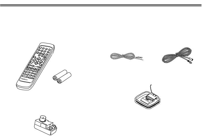
Supplied Accessories
Make sure your box contains everything listed below. If any pieces are missing, contact your nearest Onkyo dealer.
The number of accessories is indicated in brackets.
Remote controller (RC-453S) [1]
Batteries (size AA/R6/UM3) [2]
FM outdoor antenna (aerial) adapter [1]
(Supplied only for Asian and Austrarian models)
FM antenna (aerial) [1]
(USA and Canadian models) |
(Other models) |
AM loop antenna (aerial) [1]
6
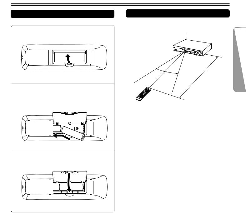
Preparing the Remote Controller
Inserting the Batteries
1 Detach the battery cover.
2Insert the two size AA/R6/UM3 batteries.
Be sure to match the + and – ends of the batteries with the diagram inside the battery compartment.
ª ·
·
ª |
3 Attach the battery cover.
Using the Remote Controller
Point the remote controller toward the remote control sensor.
Remote control sensor
30˚ |
|
|
feet) |
30˚ |
|
|
|
|
5m |
(16 |
|
|
|
|
Notes
•Place the unit away from strong light such as direct sunlight or inverted fluorescent light which can prevent proper operation of the remote controller.
•Using another remote controller of the same type in the same room or using the unit near equipment which uses infrared rays may cause operational interference.
•Do not put any object (such as a book) on the remote controller.
The buttons of the remote controller may be pressed by mistake and drain the batteries.
•Make sure the audio rack doors do not have colored glass.
Placing the unit behind such doors may prevent proper remote controller operation.
•If there is any obstacle between the remote controller and the remote control sensor, the remote controller will not operate.
Notes
•Do not mix new batteries with old batteries or different kinds of batteries.
•To avoid corrosion, remove the batteries if the remote controller is not to be used for a long time.
•Remove dead batteries immediately to avoid damage from corrosion. If the remote controller does not operate smoothly, replace both batteries at the same time.
•The life of the supplied batteries is about six months but this varies depending on usage.
7
Index to Parts and Controls
For operational instructions, refer to the page indicated in brackets.
■ Front panel
1 2 |
3 |
4 |
5 |
6 |
7 |
|
|
|
|
|
|
|
|
|
|
|
VOLUME |
|
STANDBY / ON |
|
|
|
|
|
|
|
|
|
INPUT |
|
|
ON |
|
|
|
|
|
|
|
|
|
|
|
|
|
DVD / C D |
VIDEO 1 |
VIDEO 2 |
H D |
MD / TAPE |
|
|
|
|
|
|
|
|
|
|
|
FM |
AM |
|
|
|
|
|
|
|
STANDBY |
|
|
|
|
|
|
|
|
|
|
|
|
|
PHONES |
|
|
|
SURROUND |
STEREO |
SUBWOOFER MODE |
MEMORY |
FM MODE |
TUNING/PRESET |
ACOUSTIC |
|
POWER |
|
|
|
CONTROL |
|
|||||||
ON |
OFF |
|
|
|
|
|
|
|
|
|
AV RECEIVER |
TX-L5 |
|
|
|
|
|
|
|
|
|
|
|
||
8 |
9 0 - |
= ~ ! |
@ |
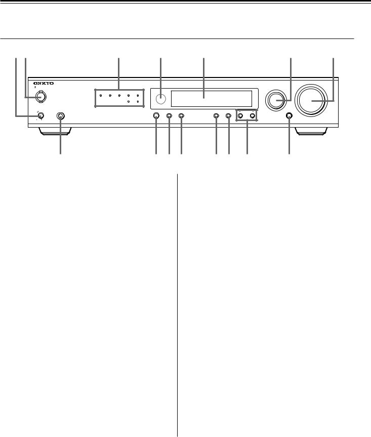
1 POWER switch [19]
Turns on the main power supply for the TX-L5. The
TX-L5 enters standby state and the STANDBY indicator lights up. Pressing the switch again to the off position (— OFF) shuts down the main power supply into the TX-L5.
•Before turning on the power, make sure all cables are properly connected.
•Turning on the TX-L5 may cause a momentary power surge that might interfere with other electrical equipment on the same circuit. If this is a problem, plug the TX-L5 into a different electrical circuit.
2 STANDBY/ON button, ON indicator, STANDBY indicator
[19]
When STANDBY/ON button is pressed to ON while the POWER switch is set to ON, the display will light to show the current volume setting for about 5 seconds then show the current sound input source and listening mode. Pressing the button again returns the
TX-L5 to the standby state. This state turns off the display, disables control functions.
3 Source indicators [23, 26]
One of these indicators lights to show the current source.
4 Remote control sensor [7]
This sensor receives the control signals from the remote controller.
5 Display [9]
6 INPUT dial [23, 26, 35]
The INPUT dial is used to select the input source.
7 VOLUME dial [23, 26]
The VOLUME dial is used to control the volume level. Turn the dial clockwise to increase the volume level and counterclockwise to decrease it.
8 PHONES jack [29]
This is a standard stereo jack for connecting stereo headphones. The audio for the front right and left speakers are sent to the headphone speakers. When the headphones are plugged in, the listening mode automatically changes to STEREO and sounds are not output from the speakers.
9 SURROUND button [32]
Press this button to select a surround mode for current input source.
0 STEREO button [32]
Press this button to change the sound to stereo.
- SUBWOOFER MODE button [20]
Press to select the subwoofer mode.
= MEMORY button [24, 25]
This button is used to assign the radio station that is currently tuned in to a preset channel or delete a previously preset station.
~ FM MODE button [23, 25]
Press to switch the reception mode between stereo and monaural. If audio is interrupted or noise interferes with audio during FM stereo broadcasting, press this button to switch to the monaural reception mode.
! TUNING/PRESET ™/£ button [23, 24]
Use these buttons to change the tuner frequency. The tuner frequency is displayed in the front display and it can be changed in
50 kHz increments for FM and 10 kHz (or 9 kHz) increments for AM.
Also, These buttons make it possible to store desired radio stations under the desired preset numbers and recall them with an easy operation.
@ ACOUSTIC CONTROL button/indicator [34]
Press to change the acoustic mode to enjoy more dynamic sounds by boosting the super bass/high frequency sounds.
8
For operational instructions, refer to the page indicated in brackets.
■ Display
1 |
|
|
2 |
3 4 |
5 |
6 7 8 |
||||||||||||||||||||||
|
|
|
|
|
|
|
|
|
|
|
|
|
|
|
|
|
|
|
|
|
|
|
|
|
|
|
|
|
|
|
|
|
|
|
|
|
|
|
|
|
|
|
|
|
|
|
|
|
|
|
|
|
|
|
|
|
|
|
|
|
|
|
|
|
|
|
|
|
|
|
|
|
|
|
|
|
|
|
|
|
|
|
RDS |
|
|
|
|
|
|
|
|
|
|
|
|
|
|
|
|
|
|
|
|
|
|
|
|
|
|
||||||
|
|
|
|
|
|
|
|
|
|
|
|
|
|
|
|
|
|
|
|
|
|
|
|
|
|
|
|
|
|
|
|
|
|
|
|
|
|
|
|
|
|
|
|
|
|
|
|
|
|
|
|
|
|
|
|
|
|
|
|
|
|
|
|
|
|
|
|
|
|
|
|
|
|
|
|
|
|
|
|
|
|
|
|
|
|
|
|
|
|
|
|
|
|
|
|
|
|
|
|
|
|
|
|
|
|
|
|
|
|
|
|
|
|
|
|
9
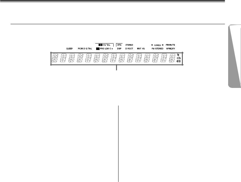
1 SLEEP indicator [29]
Lights up when the sleep timer is active.
2 Source/Listening mode indicators [26, 32]
One of these indicators lights to show the format of the current source as “PCM DIGITAL”, “Ÿ DIGITAL” or “DTS”. In addition, one of the listening mode indicators “Ÿ PRO LOGIC II”, “DSP” and “STEREO” lights according to the current listening mode.
3 MUTING indicator [29]
Flashes when the mute function is active.
4 FM STEREO indicator [23]
Lights up when an FM stereo broadcast station is received.
5 TUNED indicator [23]
Lights up when a radio station is received.
6 FM MUTE indicator [23]
Lights up to indicate FM muting. It extinguishes when the monaural reception mode is started by pressing the FM MODE button.
7 RDS indicator (European models only) [23]
Lights up when a RDS station is received.
8 MEMORY indicator [24]
Lights up when the MEMORY button is pressed in the radio station preset operation.
9 Multi function display
In usual operation, shows the current input source and volume.
When the FM or AM input is selected, it shows the frequency and preset number. When the DISPLAY button is pressed, it shows the listening mode and input source format. However, it does not show the source format when the input source signal is analog, or when the FM or AM source is selected.
9
Index to Parts and Controls
For operational instructions, refer to the page indicated in brackets.
■ Rear panel
1 |
2 |
3 |
4 5 |
6 |
7 |
8 |
DVD/CD |
VIDEO 1 |
|
VIDEO 2 |
MON |
DVD/CD |
VIDEO 1 |
VIDEO 2 MON OUT |
|
SUB |
DIGITAL INPUT |
IN |
OUT |
IN |
IN |
OUT |
IN |
OUT IN |
IN |
REMOTE |
WOOFER |
|
VIDEO |
|
|
|
|
|
|
|
CONTROL |
|
|
DVD (OPTICAL)
|
|
|
|
|
|
|
S VIDEO |
PRE OUT |
VIDEO 2 (COAXIAL) |
IN |
OUT |
IN |
IN |
OUT |
IN |
OUT |
IN |
|
|
|
|
|
|
|
|
|
|
ANTENNA |
HD |
L |
|
|
|
|
|
|
L |
(OPTICAL) |
|
|
|
|
|
|
|
|
|
AUDIO |
|
|
|
|
|
R |
|
|
|
R |
|
|
|
|
HD |
AM |
FM 75 |
DVD/CD |
VIDEO 1 |
VIDEO 2 |
MD/TAPE |
|
SURROUND CENTER SPEAKERS SPEAKER
R |
L |
FRONT SPEAKERS |
|
R |
L |
AV RECEIVER
MODEL NO. TX-L5
90
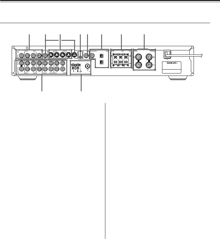
1 VIDEO (DVD/CD IN / VIDEO 1 OUT/IN / VIDEO 2 IN) [13]
There are 3 video inputs and 1 output. Connect DVD players, LD players, VCRs or other video components to the video inputs. The video output channel can be used to be connected to video tape recorder for making recordings.
2 MON OUT [12]
The monitor output includes both RCA type and S video configurations. This output is for connecting television monitors or projectors.
3 S VIDEO (DVD/CD IN / VIDEO 1 OUT/IN / VIDEO 2 IN)
[13]
There are 3 video inputs and 1 output. Connect DVD players, LD players, VCRs or other video components to the video inputs. The video output channel can be used to be connected to video tape recorder for making recordings.
4 z (REMOTE CONTROL) [18]
Connect the Onkyo components that have z connectors such as a
CD player, and cassette tape deck using the z cables provided with them. When these components are interconnected, they can be controlled from the remote controller provided with the TX-L5.
After connecting the z connectors, check the operation of the remote controller buttons for use in controlling other components
(refer to page 27).
•The z connectors are only effective if they are used in conjunction with an Onkyo amplifier with an z connector. Do not connect to a component other than Onkyo component with an z connector. Doing so may damage the TX-L5.
•Connecting z cable only does not make the system operational.
You must also connect the audio cables as well.
•If the connected component has two z connectors, you can use either one to connect to the TX-L5. The other one can be used to daisy chain with another component.
5 SUB WOOFER PRE OUT [15]
This terminal is for connecting an active subwoofer.
6 DIGITAL INPUT (DVD, HD (OPTICAL), VIDEO 2 (COAXIAL))
[12, 13]
These are the digital audio inputs. There are 2 digital inputs with optical jacks and 1 with a coaxial jack. The inputs accept digital audio signals from DVD players, hard disk recorders, CD players, or other digital source component.
7 SURROUND SPEAKERS L/R, CENTER SPEAKER [15]
Speaker terminals are provided for the center, surround left and surround right speakers.
8 FRONT SPEAKERS L/R [15]
Speaker terminals are provided for the front left, front right speakers. Speaker outputs are compatible with banana plug connectors (other than European models).
9 AUDIO L/R (DVD/CD IN / VIDEO 1 OUT/IN / VIDEO 2 IN /
HD OUT/IN / MD/TAPE OUT/IN) [12, 13]
These are the analog audio inputs and outputs. There are 5 audio inputs and 3 audio outputs. The audio inputs and outputs require RCA type connectors.
When connecting a VCR or other video component, make sure you connect the audio and video leads together (i.e., both to VIDEO 1).
0 ANTENNA [16, 17]
These terminals are for connecting the FM antenna and AM antenna.
10
For operational instructions, refer to the page indicated in brackets.
■ Remote Controller
1
2
3
4
5
6
7
8
ON STANDBY SLEEP DIMMER
DVD/CD VIDEO 1 VIDEO 2 DISPLAY
INPUT SELECTOR |
R S |
||||
HD |
MD/TAPE |
TUNER |
P |
E |
ET |
|
|||||
DVD MD |
DVD |
MD |
|
|
|
Control |
|
|
|
|
|
TOP MENU |
|
|
MENU |
||
|
ENTER |
|
|
|
|
RETURN |
|
|
SETUP |
||
|
|
PLAY |
|
|
|
SURR MODE STEREO |
SP SETUP SW MODE |
||||
TEST TONE |
CH SEL |
|
|
|
|
DISTANCE LATE NIGHT |
A.CTRL |
MUTING |
|||
|
VOLUME |
|
|
|
|
REMOTE CONTROLLER RC-453S
For detailed descriptions on the buttons, see “Front panel facilities” on pages 8.
9 |
1 STANDBY button [19] |
|
|
0 |
Put the TX-L5 in standby. |
|
-2 ON button [19]
Turns on the TX-L5.
=3 INPUT SELECTOR buttons [26, 27, 35]
For selecting the input source.
4 DVD•MD Control buttons [27]
For operating z-connected Onkyo components connected to the
TX-L5.
5 SURR MODE button [32]
Press to select the surround mode.
6 STEREO button [32]
Press to change the listening mode to stereo.
7 SP SETUP/SW MODE/TEST TONE/CH SEL/DISTANCE/
5/∞ buttons [20-22, 33]
|
For setting the output levels for each speaker. |
~ |
These buttons are provided only on the remote controller. |
|
!8 LATE NIGHT button [34]
@ |
Press to change the late night setting. |
|
This button is provided only on the remote controller. |
|
9 SLEEP button [29] |
|
For setting the sleep timer. |
|
This button is provided only on the remote controller. |
|
0 DIMMER button [28] |
|
For adjusting the brightness of the front display. |
|
This button is provided only on the remote controller. |
|
- DISPLAY button [28] |
|
For changing the display. |
|
= PRESET 5/∞ button [24] |
|
For selecting a tuner preset channel. |
|
~ MUTING button [29] |
|
Activates the mute function. |
|
This button is provided only on the remote controller. |
|
! A.CTRL button [34] |
|
Press to change the acoustic mode to boost the super bass/high |
|
frequency sounds. |
|
@ VOLUME 5/∞ button [26] |
|
For adjusting the volume. |
11

Connecting to Audio/Video Equipment
Before connecting
•Refer also to the instruction manual of each component to be connected.
•When you connect the AV Receiver to audio/video equipment, be sure to turn off the power and unplug all the units from the mains before making any connections.
•About DIGITAL INPUT (OPTICAL) jack
Remove the protective caps before making connections. When not in use, be sure to replace them.
•Connect the plugs securely.
•About the DVD, VIDEO 1 and VIDEO 2 jacks
The video input/output connections are also necessary even if you make the S video input/output connections.
 Incomplete
Insert completely
Example of monitor and audio equipment connections
TV monitor or Projector (MON OUT)
VIDEO S VIDEO
IN IN
Note
The signal that comes in from
S VIDEO IN is sent to S VIDEO
OUT. The signal that comes in from
VIDEO IN is sent to VIDEO OUT.
VIDEO
S video plug
Audio (L)
Audio (R)
Optical plug
Video connection cable (Analog signal)
S video connection cable (S video signal)
Audio connection cable (Analog signal)
Optical cable (Digital signal)
Signal flow
DVD/CD |
VIDEO 1 |
|
VIDEO 2 |
MON |
DVD/CD |
VIDEO 1 |
VIDEO 2 MON OUT |
|
SUB |
DIGITAL INPUT |
IN |
OUT |
IN |
IN |
OUT |
IN |
OUT IN |
IN |
REMOTE |
WOOFER |
|
VIDEO |
|
|
|
|
|
|
|
CONTROL |
|
|
DVD (OPTICAL)
|
|
|
|
|
|
|
S VIDEO |
PRE OUT |
VIDEO 2 (COAXIAL) |
IN |
OUT |
IN |
IN |
OUT |
IN |
OUT |
IN |
|
|
|
|
|
|
|
|
|
|
ANTENNA |
HD |
L |
|
|
|
|
|
|
L |
(OPTICAL) |
AUDIO |
|
|
|
|
|
R |
|
|
|
R |
|
|
|
|
HD |
AM |
FM 75 |
DVD/CD |
VIDEO 1 |
VIDEO 2 |
MD/TAPE |
|
SURROUND CENTER SPEAKERS SPEAKER
R |
L |
FRONT SPEAKERS R L
AV RECEIVER
DOTX-NOTL5 connect the power cord (mailns lead) at this time.
|
|
|
|
R |
L |
|
R |
L |
|
|
|
|
|
||||
|
|
|
|
|
||||
DIGITAL |
|
|
||||||
|
|
|||||||
|
|
|||||||
|
AUDIO IN |
|
AUDIO OUT |
|||||
OUT |
|
|
||||||
|
(REC) |
|
(PLAY) |
|||||
OPTICAL |
|
|
||||||
|
|
|
|
|
|
|||
Digital audio processor, Hard disk recorder etc. (HD)
R |
L |
R |
L |
AUDIO IN |
AUDIO OUT |
||
(REC) |
(PLAY) |
||
Cassette Tape deck, MD recorder, DAT deck, CD recorder (MD/TAPE)
12
 Loading...