


TX-NR585
Front Panel≫ Rear Panel≫ Remote≫
AV RECEIVER
Instruction Manual
TX-NR585
En
Table of contents
Connections
- Connecting Speakers
Playback
Setup
Troubleshooting
Appendix
Supplementary Information

2
Front Panel≫ Rear Panel≫ Remote≫
Contents
≫
Connections
≫
Playback
≫
Setup
≫
What’s in the box 5
Part Names 6
Front Panel 6
Display 8
Rear Panel 9
Remote Controller 11
Connections
Connecting speakers 13
Speaker Installation 14
Speaker Connections and “Speaker Setup” Settings 20
Speaker combinations 29
Connecting the TV 30
To ARC TV 31
To Non-ARC TV 32
Connecting Playback Devices 33
Connecting an AV Component with HDMI Jack
Mounted 33
Connecting an AV Component without HDMI Jack
Mounted 34
Connecting an Audio Component 35
Connecting an AV Component in a Separate Room
(Multi-zone Connection) 36
Connecting a Pre-main Amplier (ZONE 2) 36
Connecting Antennas 37
Network Connection 38
Connecting the Power Cord 39
Playback
AV Component Playback 41
Basic Operations 41
BLUETOOTH
®
Playback 42
Basic Operations 42
Internet Radio 43
Playing Back 43
Spotify 45
Playing Back 45
AirPlay
®
46
Basic Operations 46
DTS Play-Fi
®
47
Playing Back 47
FlareConnect
TM
48
Playing Back 48
USB Storage Device 49
Basic Operations 49
Device and Supported Format 51
Playing back les on a PC and NAS (Music Server) 52
3
Front Panel≫ Rear Panel≫ Remote≫
Contents
≫
Connections
≫
Playback
≫
Setup
≫
Windows Media
®
Player settings 52
Playing Back 53
Supported Audio Formats 56
Play Queue 57
Initial Setup 57
Adding Play Queue Information 57
Sort and Delete 58
Playing Back 58
Listening To the AM/FM Radio 59
Tuning into a Radio Station 59
Presetting a Radio Station 61
Multi-zone 63
Switch remote control mode 63
Playing Back 64
Convenience functions 65
Adjusting the tone 65
Listening Mode 66
Selecting a Listening mode 66
Listening Mode Eects 68
Selectable listening modes 71
Setup
Setup Menu 80
Menu list 80
Menu operations 82
1. Input/Output Assign 83
2. Speaker 86
3. Audio Adjust 91
4. Source 92
5. Hardware 94
6. Multi Zone 99
7. Miscellaneous 99
Quick Menu 101
Menu operations 101
Web Setup 103
Menu operations 103
Firmware Update 104
Updating Function on This Unit 104
Updating the Firmware via Network 105
Updating via USB 107
Initial Setup with Auto Start-up Wizard 109
Operations 109
Troubleshooting
When the unit is operating erratically 113
Troubleshooting 114

4
Front Panel≫ Rear Panel≫ Remote≫
Contents
≫
Connections
≫
Playback
≫
Setup
≫
Appendix
About HDMI 123
General Specications 125
5
Front Panel≫ Rear Panel≫ Remote≫
Contents
≫
Connections
≫
Playback
≫
Setup
≫
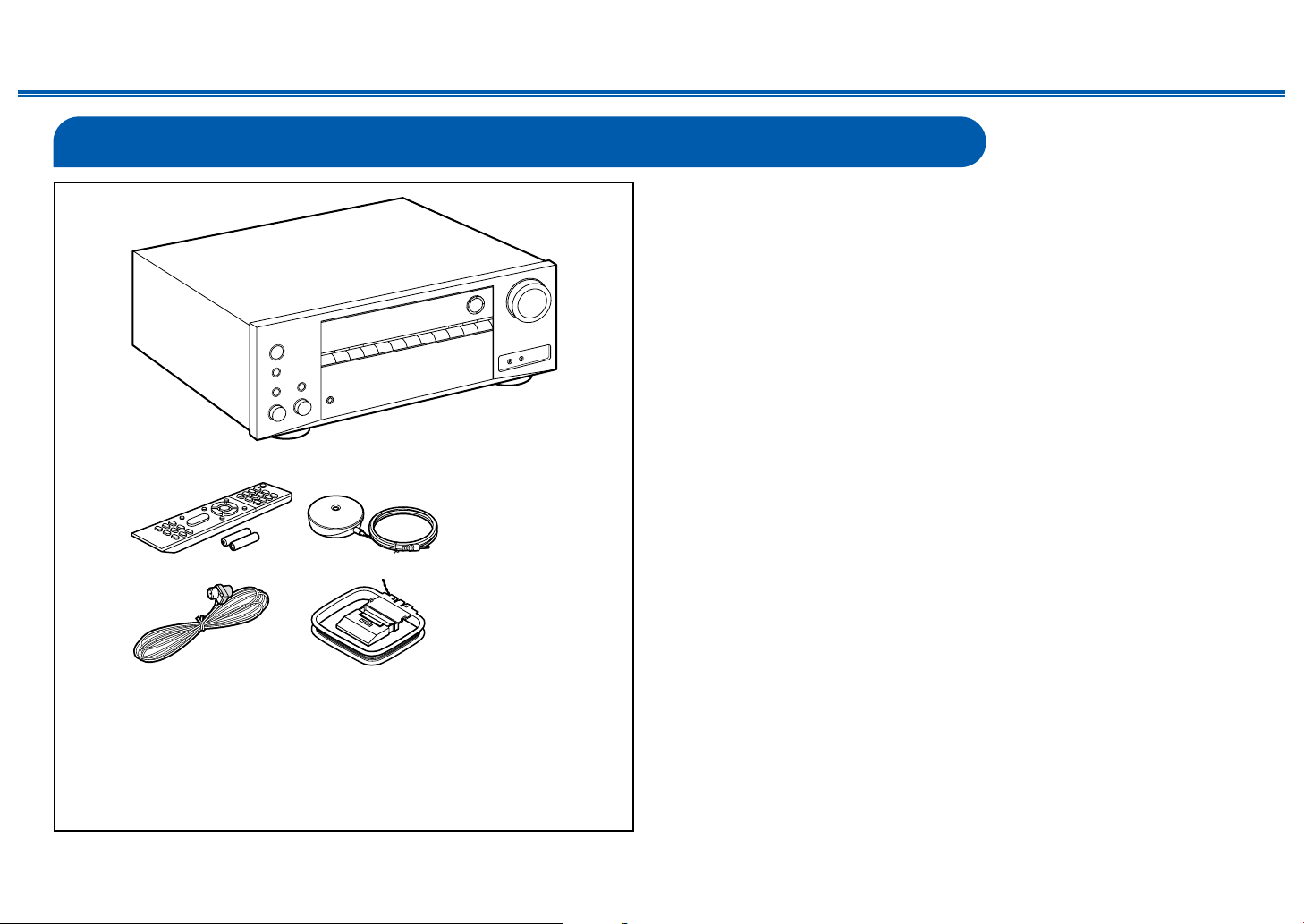
What’s in the box
1. Main unit (1)
2. Remote controller (RC-911R) (1), Batteries (AAA/R03) (2)
3. Speaker setup microphone (1)
• Used during Initial Setup.
4. Indoor FM antenna (1)
5. AM loop antenna (1)
• Quick Start Guide (1)
* This document is an online instruction manual. It is not included as an
accessory.
• Connect speakers with an impedance of 4 Ω to 16 Ω.
• The power cord must be connected only after all other connections are
completed.
• We will not accept any responsibility for damage arising from the connection
with equipment manufactured by other companies.
• Network services and content that can be used may no longer be available
if new functions are added by updating rmware or the service providers
terminate their services. Also, available services may dier depending on your
area.
• Details on the rmware update will be posted on our website and through
other means at a later date.
• Specications and appearance are subject to change without prior notice.
1
32
54

6
Contents
≫
Connections
≫
Playback
≫
Setup
≫
Front Panel≫ Rear Panel≫ Remote≫
Part Names
Front Panel
❏ For details, see ( p7)

7
Contents
≫
Connections
≫
Playback
≫
Setup
≫
Front Panel≫ Rear Panel≫ Remote≫
1. ON/STANDBY button
2. MUSIC OPTIMIZER button/indicator: Turns on/o the MUSIC OPTIMIZER
function that improves the quality of the compressed audio.
3. HYBRID STANDBY indicator: Lights if the unit enters standby mode when the
functions such as HDMI Standby Through and Network Standby that work in
standby are enabled.
4. Remote control sensor: Receives signals from the remote controller.
• The reception range of the remote controller is within a distance of approx.
16´/5 m, and an angle of 20° in vertical direction and 30° to right and left.
5. ZONE 2 button: Controls the multi-zone function. ( p64)
6. OFF button: Switches the multi-zone function o. ( p64)
7. DIMMER button: Switches the brightness of the display with three levels. It
cannot be turned o completely.
8. Display ( p8)
9. SETUP button: You can display advanced setting items on the TV and the
display to have a more enjoyable experience with this unit. ( p80)
10.
Cursor buttons ( / / / ) and ENTER button: Select an item with the
cursors, and press ENTER to conrm your selection. When using TUNER, use
them to tune in to stations. ( p59)
11.
RETURN button: Returns the display to the previous state while setting.
12.
MASTER VOLUME
13.
Press the LISTENING MODE button (above) to select a category from "Movie/
TV", "Music” and "Game", and then turn the LISTENING MODE dial (below) to
change the listening mode. ( p66)
14.
You can adjust the sound quality of the front speakers. Press the TONE button
(above) to select an item to adjust from "Bass" and "Treble", and turn the
TONE dial (below) to adjust. ( p65)
15.
PHONES jack: Connect headphones with a standard plug (Ø1/4"/6.3 mm).
16.
Input selector buttons: Switches the input to be played.
17.
SETUP MIC jack: Connect the supplied speaker setup microphone. ( p110)
18.
AUX INPUT jack: Connect a mobile music player, etc. using a stereo mini plug
cable (φ1/8″/3.5 mm).
8
Front Panel≫ Rear Panel≫ Remote≫
Contents
≫
Connections
≫
Playback
≫
Setup
≫
Display
2
77
6
5431
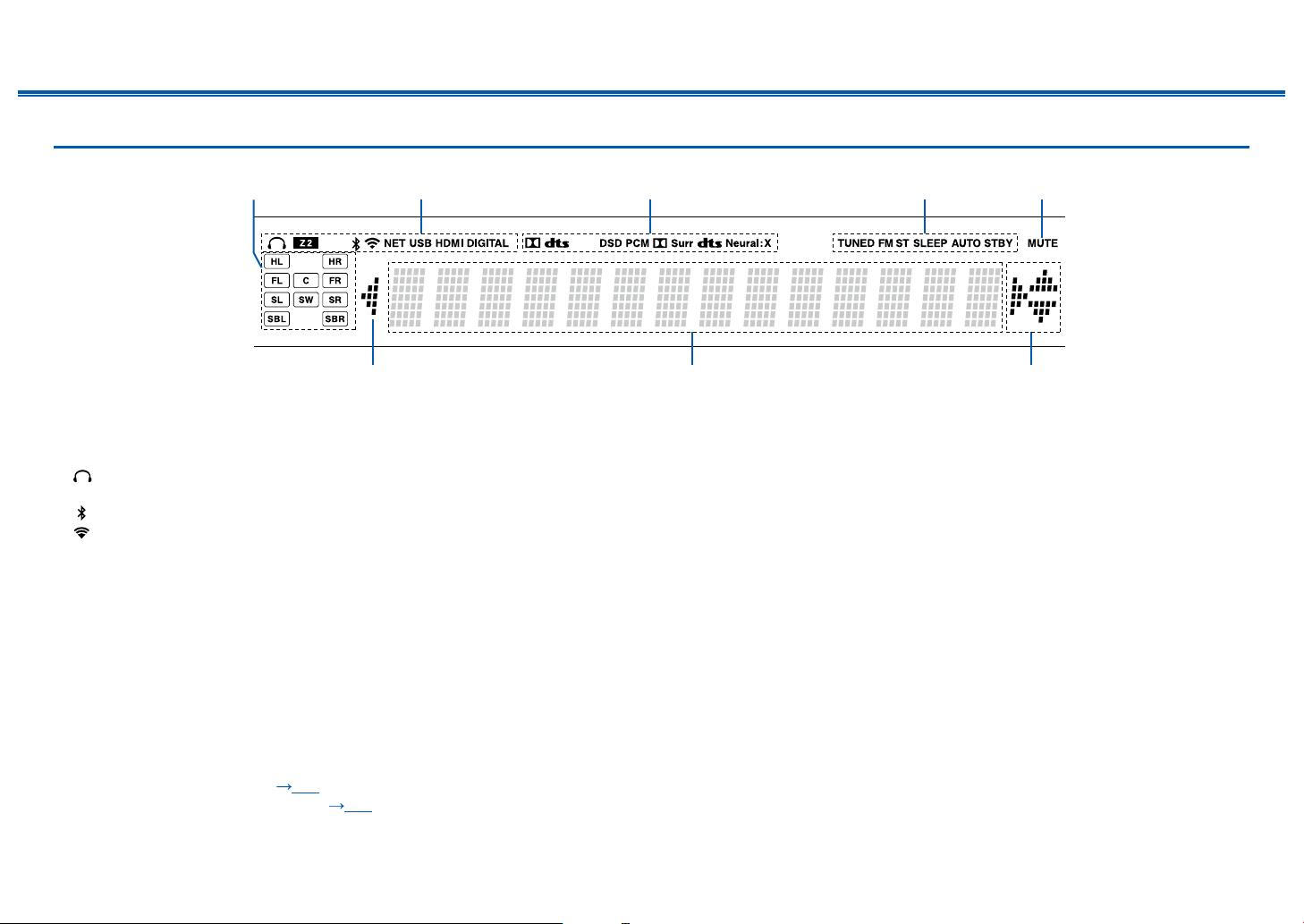
1. Speaker/Channel display: Displays the output channel that corresponds to the
selected listening mode.
2. Lights in the following conditions.
: Headphones are connected.
Z2: ZONE 2 is on.
: Connected by BLUETOOTH.
: Connected by Wi-Fi.
NET: Lights when connected to the network with the “NET” input selector. It
will blink if incorrectly connected to the network.
USB: Lights when the "NET" input selector is selected, a USB device is
connected and the USB input is selected. It will blink if the USB device is not
properly connected.
HDMI: HDMI signals are input and the HDMI input is selected.
DIGITAL: Digital signals are input and the digital input is selected.
3. Lights according to the type of input digital audio signal and the listening
mode.
4. Lights in the following conditions.
TUNED: Receiving AM/FM radio.
FM ST: Receiving FM stereo.
SLEEP: Sleep timer is set. ( p97)
AUTO STBY: Auto Standby is set. ( p98)
5. Blinks when muting is on.
6. Displays various information of the input signals.
7. This may light when operating with the "NET" input selector.

9
Contents
≫
Connections
≫
Playback
≫
Setup
≫
Front Panel≫ Rear Panel≫ Remote≫
Rear Panel
❏ For details, see ( p10)
180°
90°

10
Contents
≫
Connections
≫
Playback
≫
Setup
≫
Front Panel≫ Rear Panel≫ Remote≫
1. DIGITAL IN OPTICAL/COAXIAL jacks: Input TV or AV component digital audio
signals with a digital optical cable or digital coaxial cable.
2. TUNER AM/FM terminal: Connect the supplied antennas.
3. VIDEO IN jacks: Input AV component video signals with an analog video cable.
4. Wireless antenna: Used for Wi-Fi connection or when using a BLUETOOTH-
enabled device. Adjust the angles according to the connection status.
5. USB port: Connect a USB storage device to play music les. ( p49) You
can also supply power (5 V/1 A) to USB devices with a USB cable.
6. ETHERNET port: Connect to the network with a LAN cable.
7. COMPONENT VIDEO IN jacks: Input AV component video signals with a
component video cable. (Compatible only with 480i or 576i resolution.)
8. HDMI OUT jacks: Transmit video signals and audio signals with an HDMI
cable connected to a TV.
9. HDMI IN jacks: Transmit video signals and audio signals with an HDMI cable
connected to an AV component.
10.
Power cord
11.
GND terminal: Connect the ground wire of the turntable.
12.
AUDIO IN jacks: Input TV or AV component audio signals with an analog audio
cable.
13.
SPEAKERS terminals: Connect speakers with speaker cables. (Compatible
with banana plugs)
14.
ZONE 2 LINE OUT jacks: Output audio signals with an analog audio cable
connected to a pre-main amplier in a separate room (ZONE 2).
15.
SUBWOOFER PRE OUT jacks: Connect a powered subwoofer with a
subwoofer cable. Up to two powered subwoofers can be connected. The same
signal is output from each SUBWOOFER PRE OUT jack.
11
Contents
≫
Connections
≫
Playback
≫
Setup
≫
Front Panel≫ Rear Panel≫ Remote≫
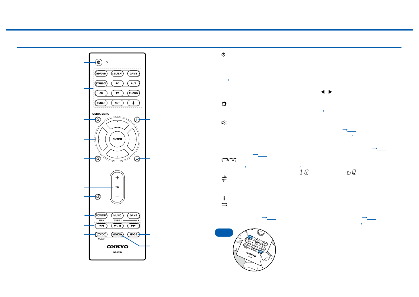
Remote Controller
1. ON/STANDBY button
2. Input selector buttons: Switches the input to be played.
3. Q (QUICK MENU) button: Pressing this button during playback can make
settings such as "Tone" and "Level” quickly on the TV screen while playing.
( p101)
4. Cursor buttons and ENTER button: Select an item with the cursors, and press
ENTER to conrm your selection. Pressing / can switch the screen when a
music folder list or le list is not displayed on one screen on the TV.
5. button: Display advanced setting items on the TV or the display to have a
more enjoyable experience with this unit. ( p80)
6. VOLUME buttons
7. button: Temporarily mutes audio. Press the button again to cancel muting.
8. LISTENING MODE button: Select a listening mode ( p66).
MAIN/ZONE 2 button: Control the multi-zone function ( p63). (The ZONE
3 button cannot be used with this unit.)
9. Play buttons: Used for playback operations for the Music Server ( p52) or
USB device ( p49).
10.
button: Used for repeat/random playback operations for the Music
Server ( p52) or USB device ( p49). Each time you press the button,
the mode switches in the order of (1-track repeat), (folder repeat), and
(random).
CLEAR button: Deletes all characters you have entered when entering text on
the TV screen.
11.
button: Switches the information on the display.
12.
button: Returns the display to the previous state while setting.
13.
MODE button: Used to switch between automatic tuning and manual tuning for
AM/FM stations ( p59), or operate the multi-zone function ( p63).
14.
MEMORY button: Used to register AM/FM radio stations. ( p61)
Tips
If the remote controller does not work: The
remote controller may have switched to the mode
for controlling ZONE 2. While pressing and holding
MODE, press the MAIN button for 3 seconds or
more until the remote indicator blinks once, and then
switch it to the mode for controlling the main room.
8
9
bk
1
2
3bl
bm
bn
bo
5
7
6
4
12
Front Panel≫ Rear Panel≫ Remote≫
Contents
≫
Connections
≫
Playback
≫
Setup
≫
Connections
Connecting speakers 13
Connecting the TV 30
Connecting Playback Devices 33
Connecting an AV Component in a Separate Room
(Multi-zone Connection) 36
Connecting Antennas 37
Network Connection 38
Connecting the Power Cord 39
13
Front Panel≫ Rear Panel≫ Remote≫
Contents
≫
Connections
≫
Playback
≫
Setup
≫
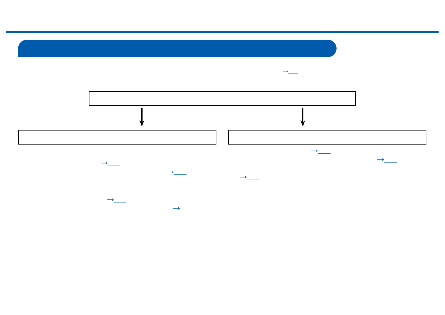
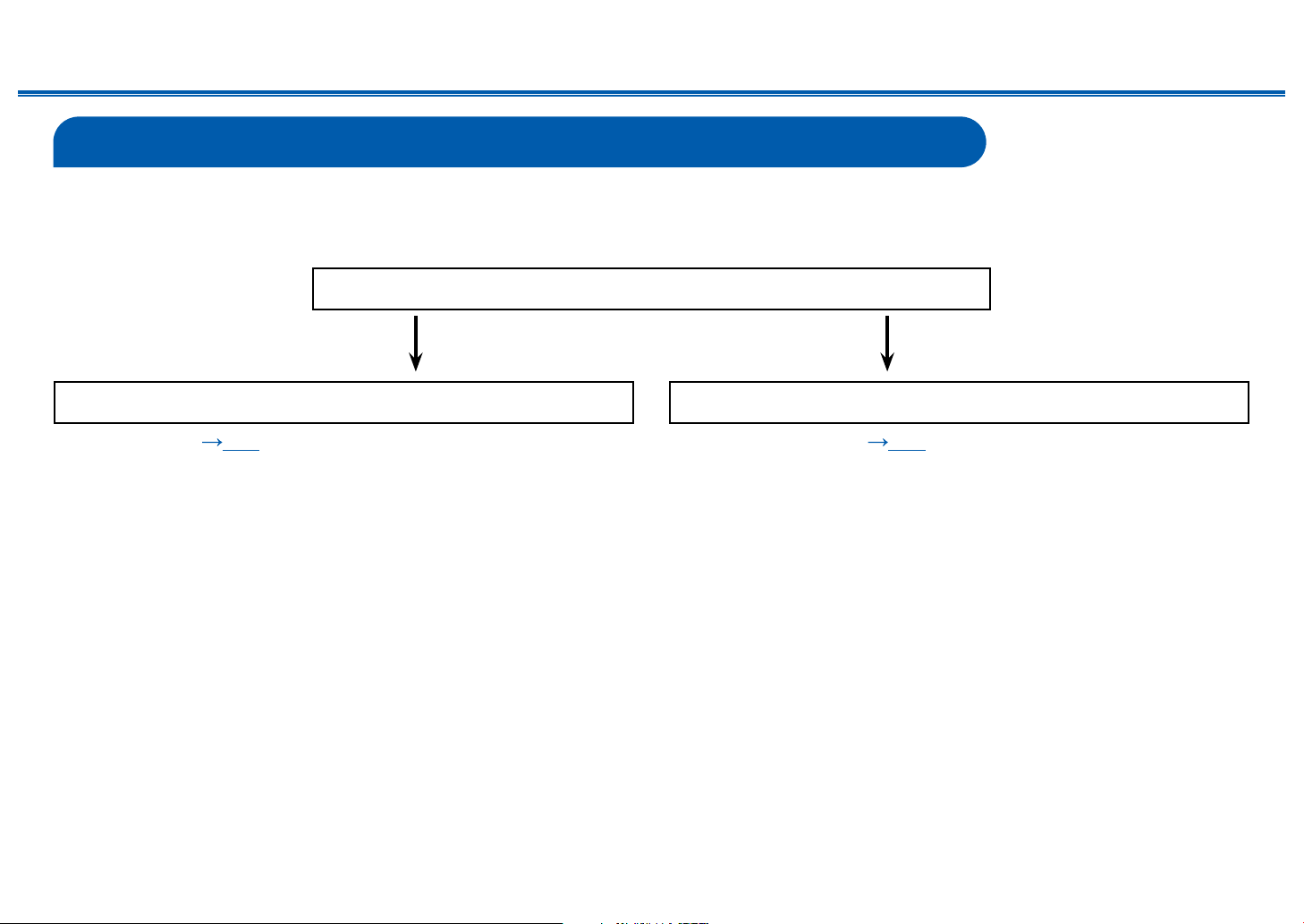
Connecting speakers
You can select the layout of speakers to be installed from various patterns when using this unit. Use the following ow chart to select the speaker layout that suits your
speakers and usage environment. You can check the connection method and default settings. Dolby Atmos ( p68) listening mode faithfully reproduces the sound
design recorded in the Dolby Atmos audio format by installing Surround Back Speakers or Height Speakers. Dolby Atmos enables the accurate placement of sound
objects that have independent motion in a three-dimensional space with even greater clarity.
Yes No
Do you enjoy sound with Dolby Atmos?
When using Surround Back Speakers
• 7.1 Channel System (
p25)
• 7.1 Channel System + ZONE SPEAKER ( p26)
When using Height Speakers
• 5.1.2 Channel System (
p27)
• 5.1.2 Channel System + ZONE SPEAKER ( p28)
• 5.1 Channel System ( p22)
• 5.1 Channel System + ZONE SPEAKER ( p23)
• 5.1 Channel System (Bi-Amping the Speakers)
( p24)
14
Front Panel≫ Rear Panel≫ Remote≫
Contents
≫
Connections
≫
Playback
≫
Setup
≫
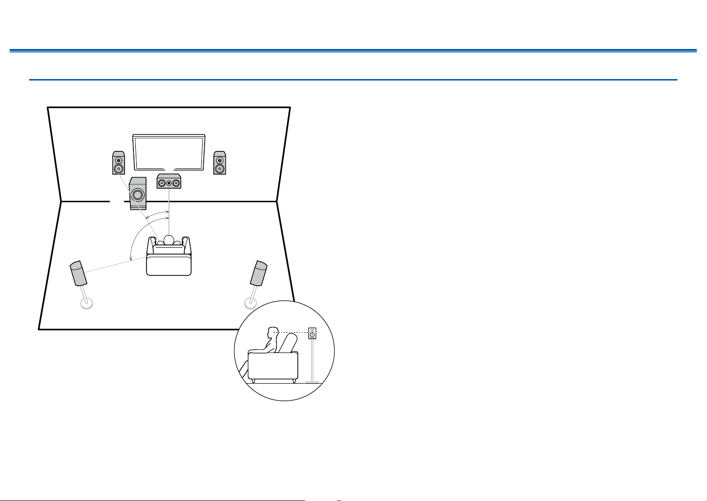
Speaker Installation
5.1 Channel System
*1
*2
12
45
3
6
*1: 22° to 30°, *2: 120°
This is a basic 5.1 Channel System. Front speakers output the front stereo
sound, and a center speaker outputs the sound of the center of the screen, such
as dialogs and vocals. Surround speakers create the back sound eld. Powered
subwoofer reproduces the bass sound, and creates the rich sound eld.
The front speakers should be positioned at ear height while the surround
speakers should be positioned just above ear height. The center speaker
should be set up facing the listening position at an angle. Placing the powered
subwoofer between the center speaker and the front speaker gives you a natural
sound even when playing music sources.
1,2 Front Speakers
3 Center Speaker
4,5 Surround Speakers
6 Powered Subwoofer

15
Front Panel≫ Rear Panel≫ Remote≫
Contents
≫
Connections
≫
Playback
≫
Setup
≫
7.1 Channel System
*1
*2
*3
12
54
87
3
6
*1: 22° to 30°, *2: 90° to 110°, *3: 135° to 150°
This is a 7.1 Channel System that consists of the basic 5.1 Channel System
( p14) and added surround back speakers. Front speakers output the
front stereo sound, and a center speaker outputs the sound of the center of the
screen, such as dialogs and vocals. Surround speakers create the back sound
eld. Powered subwoofer reproduces the bass sound, and creates the rich
sound eld. Surround back speakers improves the sense of envelopment and
connectivity of sound in the back sound eld, and provides a more real sound
eld. Furthermore, by installing surround back speakers, when the input format is
Dolby Atmos, you can select the Dolby Atmos listening mode which realizes the
most up-to-date 3D sound,
The front speakers should be positioned at ear height while the surround
speakers should be positioned just above ear height. The center speaker
should be set up facing the listening position at an angle. Placing the powered
subwoofer between the center speaker and the front speaker gives you a natural
sound even when playing music sources. The surround back speakers should be
positioned at ear height.
• If surround back speakers are installed, be sure to install surround speakers
as well.
1,2 Front Speakers
3 Center Speaker
4,5 Surround Speakers
6 Powered Subwoofer
7,8 Surround Back Speakers

16
Front Panel≫ Rear Panel≫ Remote≫
Contents
≫
Connections
≫
Playback
≫
Setup
≫
5.1.2 Channel System
A 5.1.2 Channel System is a speaker layout consisting of the basic 5.1 Channel System ( p14) and added height speakers. Select the height speakers that suit
your speakers and usage environment from the following three types.
❏ Front High Speakers/Rear High Speakers
Installation Example ( p17)
❏ Ceiling Speakers Installation Example
( p18)
❏ Dolby Enabled Speakers (Dolby Speakers)
Installation Example ( p19)

17
Front Panel≫ Rear Panel≫ Remote≫
Contents
≫
Connections
≫
Playback
≫
Setup
≫
❏ Front High Speakers/Rear High Speakers
Installation Example
*1
*2
78
78
*1: 22° to 30°, *2: 120°
3´ (0.9 m)
or more
3´ (0.9 m)
or more
This is a system with the basic 5.1 channel system ( p14) consisting of front
speakers, a center speaker, surround speakers and a powered subwoofer, and
added front high speakers or rear high speakers combined. By installing such
height speakers, when the input format is Dolby Atmos, you can select the Dolby
Atmos listening mode which realizes the most up-to-date 3D sound including
overhead sound. Front high speakers or rear high speakers should be installed at
least 3´/0.9 m higher than the front speakers.
Front high speakers should be installed directly above the front speakers, and the
distance between the rear high speakers should match the distance between the
front speakers. In both cases, the speakers should be set up facing the listening
position at an angle.
7,8 Height Speakers
Choose one of the following:
• Front High Speakers
• Rear High Speakers
18
Front Panel≫ Rear Panel≫ Remote≫
Contents
≫
Connections
≫
Playback
≫
Setup
≫
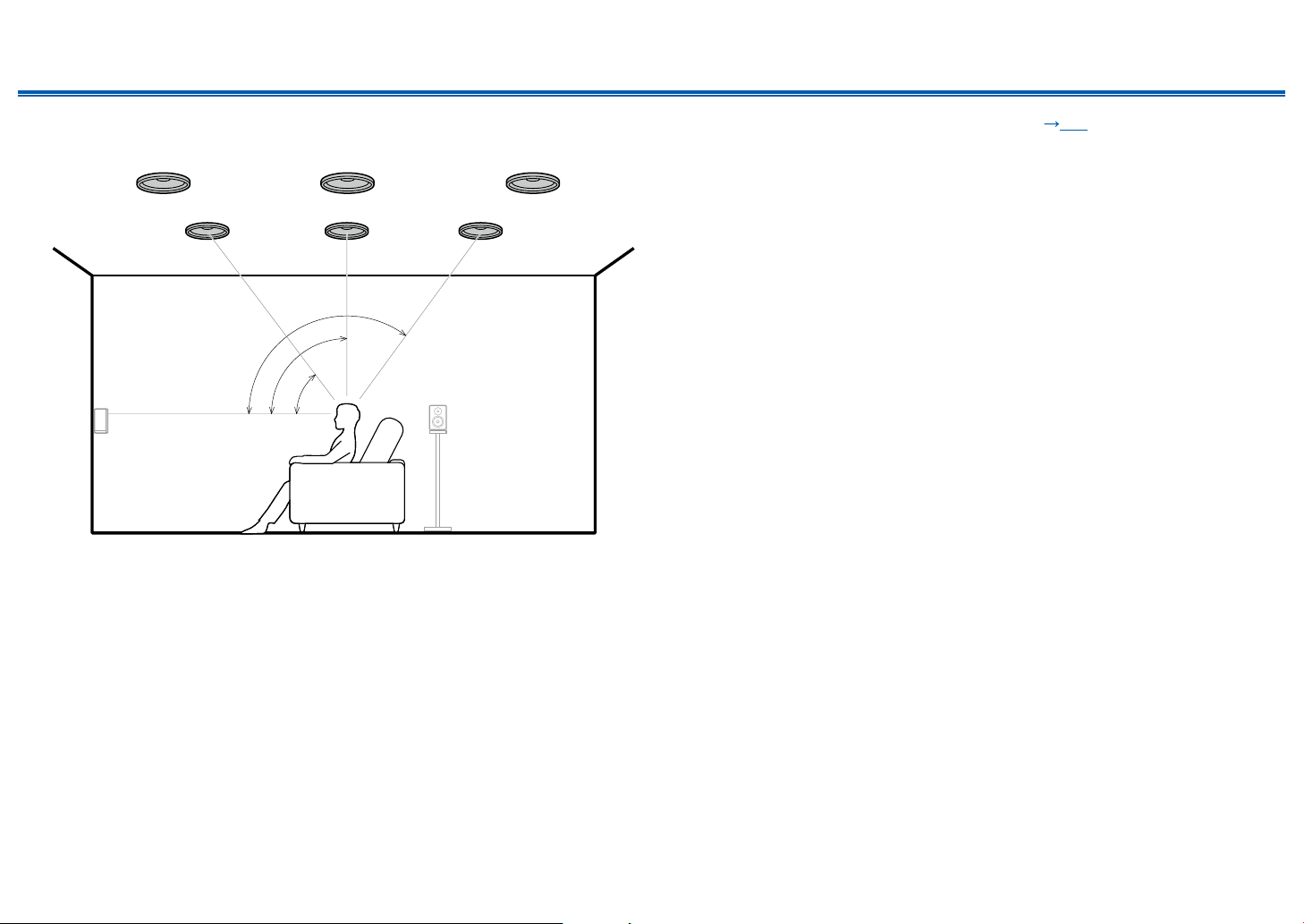
❏ Ceiling Speakers Installation Example
*1
*2
*3
7
888
77
*1: 30° to 55°, *2: 65° to 100°, *3: 125° to 150°
This is a system with the basic 5.1 channel system ( p14) consisting of front
speakers, a center speaker, surround speakers and a powered subwoofer, and
added top front speakers or top middle speakers or top rear speakers combined.
By installing such height speakers, when the input format is Dolby Atmos, you
can select the Dolby Atmos listening mode which realizes the most up-to-date
3D sound including overhead sound. Install the top front speakers on the ceiling
anterior to the seating position, top middle speakers on the ceiling directly above
the seating position, and top rear speakers on the ceiling posterior to the seating
position. The distance between each pair should match the distance between the
front speakers.
• Dolby Laboratories recommends the setups of these types of height speakers
to obtain the best Dolby Atmos eect.
7,8 Height Speakers
Choose one of the following:
• Top Front Speakers
• Top Middle Speakers
• Top Rear Speakers
19
Front Panel≫ Rear Panel≫ Remote≫
Contents
≫
Connections
≫
Playback
≫
Setup
≫
❏ Dolby Enabled Speakers (Dolby Speakers)
Installation Example
*1
*2
78
78
*1: 22° to 30°, *2: 120°
This is a system with the basic 5.1 channel system ( p14) consisting of front
speakers, a center speaker, surround speakers and a powered subwoofer, and
added Dolby enabled speakers (front) or Dolby enabled speakers (surround)
combined. Dolby enabled speakers are special speakers designed to face the
ceiling, so that the sound is heard from overhead by bouncing the sound o the
ceiling. By installing such height speakers, when the input format is Dolby Atmos,
you can select the Dolby Atmos listening mode which realizes the most up-to-
date 3D sound including overhead sound.
Install them either on the front speakers or on the surround speakers.
7,8 Height Speakers
Choose one of the following:
• Dolby Enabled Speakers (Front)
• Dolby Enabled Speakers (Surround)
20
Front Panel≫ Rear Panel≫ Remote≫
Contents
≫
Connections
≫
Playback
≫
Setup
≫
Speaker Connections and “Speaker Setup” Settings
Connections
(Note) Speaker Impedance
Connect speakers with an impedance of 4 Ω to 16 Ω. If any of the speakers to
be connected has an impedance of 4 Ω or more and 6 Ω or less, the setting is
required in the Setup menu after the Initial Setup ( p109) is completed. Press
on the remote controller, and set “2. Speaker” - “Conguration” - “Speaker
Impedance” to “4ohms”.
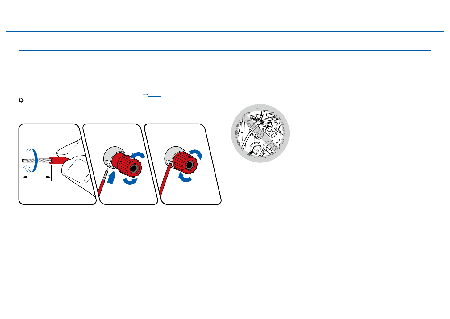
Connect the Speaker Cables
1/2˝
(12 mm)
Make correct connection between the unit's jacks and speaker's jacks (+ side to
+ side, and - side to - side) for each channel. If the connection is wrong, a bass
sound will not be reproduced properly due to reverse phase. Twist the wires
exposed from the tip of the speaker cable so that the wires do not stick out of the
speaker terminal when connecting. If the exposed wires touch the rear panel,
or the + side and – side wires touch each other, the protection circuit will be
activated.

21
Front Panel≫ Rear Panel≫ Remote≫
Contents
≫
Connections
≫
Playback
≫
Setup
≫
Connect the Subwoofer
a
a Subwoofer cable
Connect a powered subwoofer with this unit using a subwoofer cable. Up to two
powered subwoofers can be connected. The same signal is output from each
SUBWOOFER PRE OUT jack.

22
Front Panel≫ Rear Panel≫ Remote≫
Contents
≫
Connections
≫
Playback
≫
Setup
≫
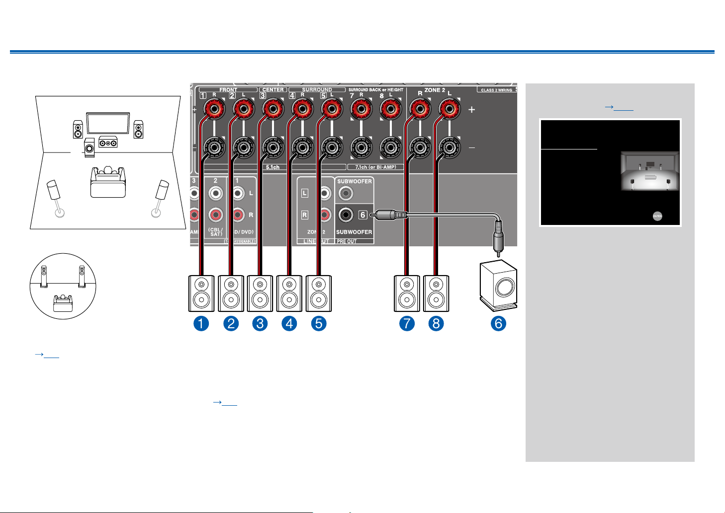
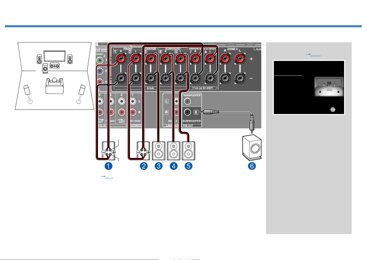
5.1 Channel System
12
45
3
6
This is a basic 5.1 Channel System. For details of the speaker layout, refer to “Speaker Installation” ( p14).
“Speaker Setup” settings during
Initial Setup ( p110)
Speaker Setup
Speaker Channels
Subwoofer
Height Speaker
Zone Speaker
Bi-Amp
Select how many speakers you have.
Next
5.1 ch
< >
Yes
---
No
No
• Speaker Channels: 5.1 ch
• Subwoofer: Yes
• Height Speaker: ---
• Zone Speaker: No
• Bi-Amp: No
23
Front Panel≫ Rear Panel≫ Remote≫
Contents
≫
Connections
≫
Playback
≫
Setup
≫
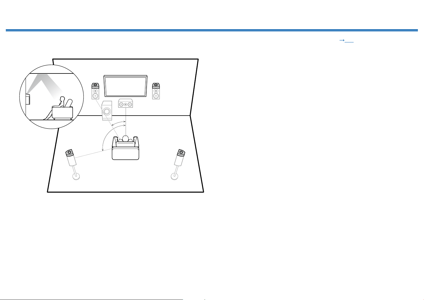
5.1 Channel System + ZONE SPEAKER
MAIN ROOM
12
45
3
6
MAIN ROOM: This is a basic 5.1 Channel System. For details of the speaker layout, refer to “Speaker Installation”
( p14).
ZONE 2: You can enjoy 2-ch audio in the separate room (ZONE 2) while performing 5.1-ch playback in the main room
(where this unit is located). The same source can be played back in the main room and ZONE 2 simultaneously. Also,
dierent sources can be played back in both rooms. To output audio from an externally connected AV component to ZONE
2, use an analog audio cable for connection. ( p36)
“Speaker Setup” settings during
Initial Setup ( p110)
Speaker Setup
Speaker Channels
Subwoofer
Height Speaker
Zone Speaker
Bi-Amp
Select how many speakers you have.
Next
5.1 ch
< >
Yes
---
Zone 2
No
• Speaker Channels: 5.1 ch
• Subwoofer: Yes
• Height Speaker: ---
• Zone Speaker: Zone 2
• Bi-Amp: No
ZONE 2
78
24
Front Panel≫ Rear Panel≫ Remote≫
Contents
≫
Connections
≫
Playback
≫
Setup
≫
5.1 Channel System (Bi-Amping the Speakers)
12
45
3
6
For high-
frequency
For low-
frequency
You can congure a 5.1 Channel System ( p14) by connecting front speakers that support Bi-Amping connection.
The Bi-Amping connection can improve the quality of the low and high pitched ranges. Be sure to remove the jumper bar
connecting between the woofer jacks and tweeter jacks of the Bi-Amping supported speakers. Refer to the instruction
manual of your speakers as well.
“Speaker Setup” settings during
Initial Setup ( p110)
Speaker Setup
Speaker Channels
Subwoofer
Height Speaker
Zone Speaker
Bi-Amp
Select how many speakers you have.
Next
5.1 ch
< >
Yes
---
No
Yes
• Speaker Channels: 5.1 ch
• Subwoofer: Yes
• Height Speaker: ---
• Zone Speaker: No
• Bi-Amp: Yes
25
Front Panel≫ Rear Panel≫ Remote≫
Contents
≫
Connections
≫
Playback
≫
Setup
≫
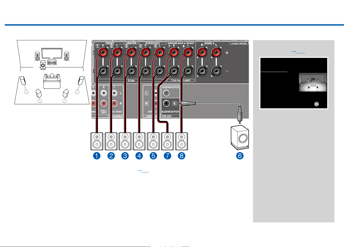
7.1 Channel System
12
5 4
87
3
6
This is a 7.1 Channel System that consists of the basic 5.1 Channel System and added surround back speakers.
For details of the speaker layout, refer to “Speaker Installation” ( p15).
“Speaker Setup” settings during
Initial Setup ( p110)
Speaker Setup
Speaker Channels
Subwoofer
Height Speaker
Zone Speaker
Bi-Amp
Select how many speakers you have.
Next
7.1 ch
< >
Yes
---
No
No
• Speaker Channels: 7.1 ch
• Subwoofer: Yes
• Height Speaker: ---
• Zone Speaker: No
• Bi-Amp: No
26
Front Panel≫ Rear Panel≫ Remote≫
Contents
≫
Connections
≫
Playback
≫
Setup
≫
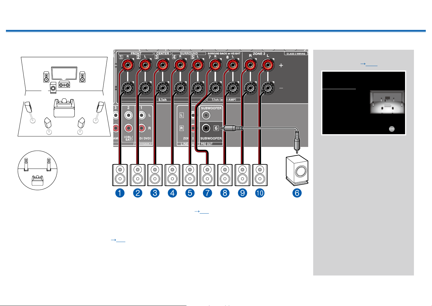
7.1 Channel System + ZONE SPEAKER
MAIN ROOM
12
5 4
87
3
6
MAIN ROOM: This is a 7.1 Channel System that consists of the basic 5.1 Channel System and added surround back
speakers. For details of the speaker layout, refer to “Speaker Installation” ( p15).
ZONE 2: You can enjoy 2-ch audio in the separate room (ZONE 2) while performing playback in the main room (where
this unit is located). The same source can be played back in the main room and ZONE 2 simultaneously. Also, dierent
sources can be played back in both rooms. To output audio from an externally connected AV component to ZONE 2, use
an analog audio cable for connection. ( p36)
• While ZONE 2 playback is being performed, surround back speakers installed in the main room cannot play audio.
“Speaker Setup” settings during
Initial Setup ( p110)
Speaker Setup
Speaker Channels
Subwoofer
Height Speaker
Zone Speaker
Bi-Amp
Select how many speakers you have.
Next
7.1 ch
< >
Yes
---
Zone 2
No
• Speaker Channels: 7.1 ch
• Subwoofer: Yes
• Height Speaker: ---
• Zone Speaker: Zone 2
• Bi-Amp: No
ZONE 2
bk 9

27
Front Panel≫ Rear Panel≫ Remote≫
Contents
≫
Connections
≫
Playback
≫
Setup
≫
5.1.2 Channel System
78
1
3
2
45
6
This is a combination of the 5.1 Channel System and front high speakers. A front high speaker is a type of height speaker.
You can select only one set of height speakers from the following three types for connection.
❏ Front High Speakers/Rear High Speakers Installation Example ( p17)
❏ Ceiling Speakers Installation Example ( p18)
❏ Dolby Enabled Speakers (Dolby Speakers) Installation Example ( p19)
“Speaker Setup” settings during
Initial Setup ( p110)
Speaker Setup
Speaker Channels
Subwoofer
Height Speaker
Zone Speaker
Bi-Amp
Select how many speakers you have.
Next
5.1.2 ch
< >
Yes
Front High
No
No
• Speaker Channels: 5.1.2 ch
• Subwoofer: Yes
• Height Speaker: Select the type of
height speaker actually installed.
• Zone Speaker: No
• Bi-Amp: No

28
Front Panel≫ Rear Panel≫ Remote≫
Contents
≫
Connections
≫
Playback
≫
Setup
≫
5.1.2 Channel System + ZONE SPEAKER
78
1
3
2
45
6
MAIN ROOM
MAIN ROOM: This is a combination of the 5.1 Channel System and front high speakers. A front high speaker is a type of
height speaker. You can select only one set of height speakers from the following three types for connection.
❏ Front High Speakers/Rear High Speakers Installation Example ( p17)
❏ Ceiling Speakers Installation Example ( p18)
❏ Dolby Enabled Speakers (Dolby Speakers) Installation Example ( p19)
ZONE 2: You can enjoy 2-ch audio in the separate room (ZONE 2) while performing playback in the main room (where
this unit is located). The same source can be played back in the main room and ZONE 2 simultaneously. Also, dierent
sources can be played back in both rooms. To output audio from an externally connected AV component to ZONE 2, use
an analog audio cable for connection. ( p36)
• While ZONE 2 playback is being performed, height speakers installed in the main room cannot play audio.
“Speaker Setup” settings during
Initial Setup ( p110)
Speaker Setup
Speaker Channels
Subwoofer
Height Speaker
Zone Speaker
Bi-Amp
Select how many speakers you have.
Next
5.1.2 ch
< >
Yes
Front High
Zone 2
No
• Speaker Channels: 5.1.2 ch
• Subwoofer: Yes
• Height Speaker: Select the type of
height speaker actually installed.
• Zone Speaker: Zone 2
• Bi-Amp: No
ZONE 2
bk 9
29
Front Panel≫ Rear Panel≫ Remote≫
Contents
≫
Connections
≫
Playback
≫
Setup
≫
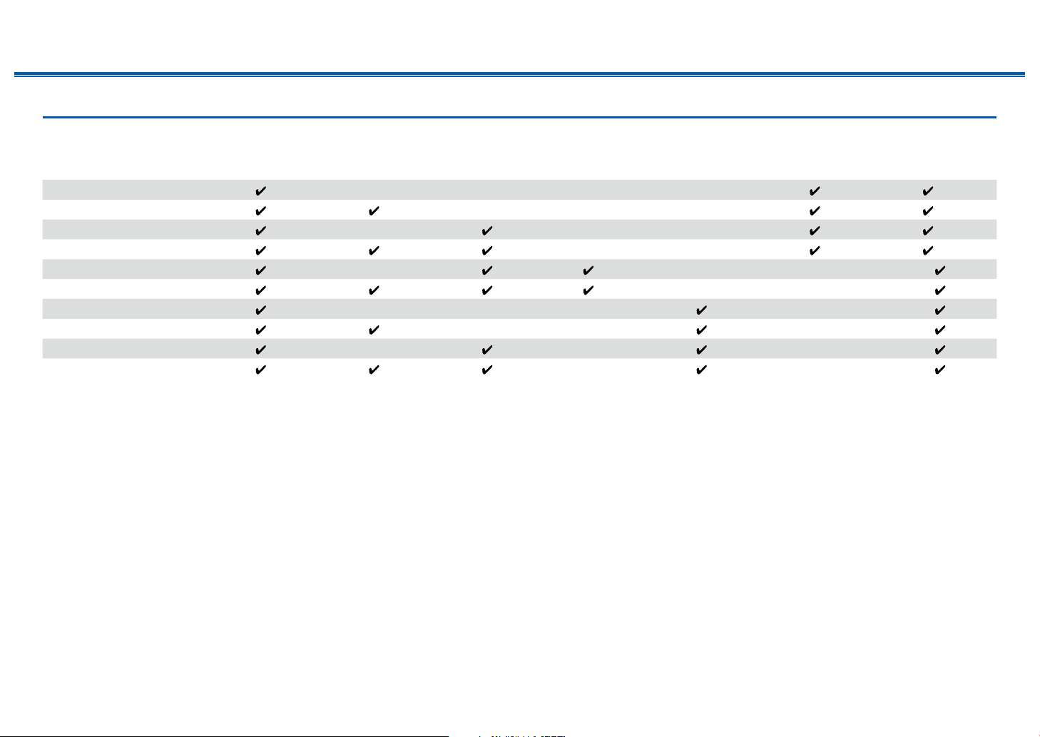
Speaker combinations
• Up to two powered subwoofers can be connected in either combination.
Speaker Channels FRONT CENTER SURROUND
SURROUND
BACK
HEIGHT Bi-AMP
ZONE 2
(ZONE SPEAKER)
2.1 ch
(*1) (*1)
3.1 ch
(*1) (*1)
4.1 ch
(*1) (*1)
5.1 ch
(*1) (*1)
6.1 ch
(*2)
7.1 ch
(*2)
2.1.2 ch
(*3)
3.1.2 ch
(*3)
4.1.2 ch
(*3)
5.1.2 ch
(*3)
(*1) You can select either Bi-AMP or ZONE SPEAKER.
(*2) When audio is being output from the ZONE SPEAKER, surround back speakers cannot play audio.
(*3) When audio is being output from the ZONE SPEAKER, height speakers cannot play audio.
30
Front Panel≫ Rear Panel≫ Remote≫
Contents
≫
Connections
≫
Playback
≫
Setup
≫
Connecting the TV
Connect this unit between a TV and AV component. Connecting this unit with the TV can output the video and audio signals of the AV component to the TV, or play the
audio of the TV on this unit. Connection with the TV diers depending on whether the TV supports the ARC (Audio Return Channel) function or not. The ARC function
transmits the audio signals of the TV via an HDMI cable, and plays the audio of the TV on this unit. To check if the TV supports the ARC function, refer to the instruction
manual of the TV, etc.
Yes No
Does your TV support the ARC function?
• To ARC TV ( p31) • To Non-ARC TV ( p32)
 Loading...