


Audio Video Control Receiver
TX-DS656
Instruction Manual
|
|
|
|
|
|
|
|
|
|
|
|
MASTER VOLUME |
|
|
|
|
|
|
|
|
|
SMART SCAN CONTROLLER |
|
||
|
|
|
|
|
|
|
|
|
|
|
PRESET |
|
SYSTEM |
|
|
|
|
|
|
|
|
|
|
|
|
|
|
|
|
|
|
|
|
|
|
|
TUNING |
|
|
|
|
|
|
|
|
|
|
|
|
SURROUND |
|
|
|
|
|
|
|
|
|
ENTER |
|
PARAMETER |
|
|
STAND-BY |
|
|
|
|
|
|
|
|
|
|
|
|
POWER |
|
|
|
|
|
|
|
|
|
|
|
|
ON OFF |
|
SPEAKERS |
|
|
|
|
|
|
|
3-D BASS |
|
|
|
|
MAIN |
REMOTE |
|
|
|
|
|
|
|
|
|
|
|
|
|
REC OUT |
MULTI SOURCE |
Re-EQ |
MIDNIGHT |
|
|
|
||
|
|
|
|
THEATER |
|
MIN |
MAX |
|||||
|
|
DIGITAL AUDIO |
MULTI CH INPUT |
|
|
|
|
|
|
|
|
|
|
|
SELECTOR |
|
|
PTY/TP |
DISPLAY CHARACTER AUTO TUN |
SCAN GROUP |
MEMORY FM MUTE/MODE |
TREBLE |
|||
|
|
|
|
|
|
|
|
|
|
|
BASS |
|
|
|
|
|
|
|
|
|
|
|
|
CLEAR |
|
PHONES |
VIDEO 3/VIDEO CAM INPUT |
|
|
|
|
|
|
|
|
|
|
|
|
|
DVD |
VIDEO-1 |
VIDEO-2 |
VIDEO-3 |
TAPE-1 |
TAPE-2 |
FM |
AM |
PHONO |
CD |
|
|
|
|
VCR-1 |
VCR-2 / TV |
CAM |
M D |
MONITOR |
|
|
|
|
|
S VIDEO |
VIDEO |
L AUDIO R(MONO) |
|
|
|
|
|
|
|
|
|
|
AUDIO VIDEO CONTROL RECEIVER TX-DS656
Thank you for purchasing the Onkyo Audio Video Control Receiver.
Please read this manual thoroughly before making connections and turning on the power.
Following the instructions in this manual will enable you to obtain optimum performance and listening enjoyment from your new Audio Video Control Receiver.
Please retain this manual for future reference.
Contents |
|
Before using |
|
Important Safeguards ........................... |
2 |
Precautions ........................................... |
3 |
Features ................................................ |
4 |
Supplied accessories ............................ |
4 |
Before using this unit ........................... |
5 |
Preparation |
|
Connection ........................................... |
6 |
On-screen setting ............................... |
18 |
Speaker system setup ......................... |
21 |
Operation |
|
Input source selection and surround |
|
setup ................................................. |
25 |
Listening to FM/AM broadcasts ........ |
32 |
Receiving RDS broadcasts |
|
(European models only) ................... |
36 |
Using the Surround modes ................. |
38 |
Recording from a source .................... |
42 |
Using the TAPE-2 MONITOR |
|
function ............................................ |
44 |
Using the other remote controller functions |
|
with the supplied remote controller ..... |
45 |
Multi-room system connections ......... |
46 |
A few important notes |
|
Troubleshooting ................................. |
50 |
Specifications ..................................... |
52 |
Control positions and names .............. |
53 |
WARNING
TO REDUCE THE RISK OF FIRE OR ELECTRIC SHOCK, DO NOT EXPOSE THIS APPLIANCE TO RAIN OR MOISTURE.
CAUTION
TO REDUCE THE RISK OF ELECTRIC SHOCK, DO NOT REMOVE COVER (OR BACK). NO USERSERVICEABLE PARTS INSIDE. REFER SERVICING TO QUALIFIED SERVICE PERSONNEL.
WARNING |
|
AVIS |
RISK OF ELECTRIC SHOCK |
|
RISQUE DE CHOC ELECTRIQUE |
DO NOT OPEN |
|
NE PAS OUVRIR |
|
|
|
•The lightning flash with arrowhead symbol, within an equilateral triangle, is intended to alert the user to the presence of uninsulated "dangerous voltage" within the product's enclosure that may be of sufficient magnitude to constitute a risk of electric shock to persons.
•The exclamation point within an equilateral triangle is intended to alert the user to the presence of important operating and maintenance (servicing) instructions in the literature accompanying the product.
Important Safeguards
1.Read Instructions – All the safety and operating instructions should be read before the appliance is operated.
2.Retain Instructions – The safety and operating instructions should be retained for future reference.
3.Heed Warnings – All warnings on the appliance and in the operating instructions should be adhered to.
4.Follow Instructions – All operating and use instructions should be followed.
5.Water and Moisture – The appliance should not be used near water - for example, near a bathtub, washbowl, kitchen sink, laundry tub, in a wet basement, or near a swimming pool, and the like.
6.Carts and Stands – The appliance should be used only with a cart or stand that is recommended by the manufacturer.
6A. An appliance and cart combination |
PORTABLE CART |
should be moved with care. Quick stops, |
WARNING |
excessive force, and uneven surfaces |
|
may cause the appliance and cart |
|
combination to overturn. |
|
|
S3125A |
7.Wall or Ceiling Mounting – The appliance should be mounted to a wall or ceiling only as recommended by the manufacturer.
8.Ventilation – The appliance should be situated so that its location or position does not interfere with its proper ventilation. For example, the appliance should not be situated on a bed, sofa, rug, or similar surface that may block the ventilation openings; or if placed in a built-in installation, such as a bookcase or cabinet that may impede the flow of air through the ventilation openings, there should be free space of at least 20 cm (8 in.) and an opening behind the appliance.
9.Heat – The appliance should be situated away from heat sources such as radiators, heat registers, stoves, or other appliances (including amplifiers) that produce heat.
10.Power Sources – The appliance should be connected to a power supply only of the type described in the operating instructions or as marked on the appliance.
11.Polarization – If the appliance is provided with a polarized plug having one blade wider than the other, please read the following information: The polarization of the plug is a safety feature. The polarized plug will only fit the outlet one way. If the plug does not fit fully into the outlet, try reversing it. If there is still trouble, the user should seek the services of a qualified electrician. Under no circumstances should the user attempt to defeat the polarization of the plug.
12.Power-Cord Protection – Power-supply cords should be routed so that they are not likely to be walked on or pinched by items placed upon or against them, especially near plugs, convenience receptacles, and the point where they exit from the appliance.
13.Cleaning – The appliance should be cleaned only as recommended by the manufacturer.
14.Power Lines – An outdoor antenna should be located away from power lines.
15.Nonuse Periods – The power cord of the appliance should be unplugged from the outlet when left unused for a long period of time.
16.Object and Liquid Entry – Care should be taken so that objects do not fall and liquids are not spilled into the enclosure through openings.
17.Damage Requiring Service – The appliance should be serviced by qualified service personnel when:
A.The power-supply cord or the plug has been damaged; or
B.Objects have fallen, or liquid has been spilled into the appliance; or
C.The appliance has been exposed to rain; or
D.The appliance does not appear to operate normally or exhibits a marked change in performance; or
E.The appliance has been dropped, or the enclosure damaged.
18.Servicing – The user should not attempt to service the appliance beyond that described in the operating instructions. All other servicing should be referred to qualified service personnel.
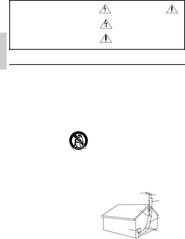
19.Outdoor Antenna Grounding - If an outside antenna is connected to the receiver, be sure the antenna system is grounded so as to provide some protection against voltage surges and built up static charges. Article 810 of the National Electrical Code, ANSI/NFPA 70, provides information with regard to proper grounding of the mast and supporting structure, grounding of the lead-in wire to an antenna-discharge unit, size of grounding conductors, location of antenna-discharge unit, connection to grounding electrodes, and requirements for the grounding electrode. See Figure 1.
ANTENNA
LEAD IN
WIRE
GROUND
CLAMP
ANTENNA DISCHARGE UNIT (NEC SECTION 810-20)
ELECTRIC
SERVICE
EQUIPMENT
GROUNDING CONDUCTORS (NEC SECTION 810-21)

 GROUND CLAMPS

 POWER SERVICE GROUNDING
ELECTRODE SYSTEM
(NEC ART 250, PART H)
NEC – NATIONAL ELECTRICAL CODE
2

Precautions
1. Warranty Claim
You can find the serial number on the rear panel. In case of warranty claim, please report this number.
2. Recording Copyright
Recording of copyrighted material for other than personal use is illegal without permission of the copyright holder.
3. AC Fuse
The fuse is located inside the chassis and is not user-serviceable. If power does not come on, contact your Onkyo authorized service station.
4. Care
From time to time you should wipe off the front and rear panels and the cabinet with a soft cloth. For heavier dirt, dampen a soft cloth in a weak solution of mild detergent and water, wring it out dry, and wipe away the dirt. Following this, dry immediately with a clean cloth. Do not use rough material, thinners, alcohol or other chemical solvents or cloths since these may damage the finish or remove the panel lettering.
5. Power
WARNING
BEFORE PLUGGING IN THE UNIT FOR THE FIRST TIME, READ THE FOLLOWING SECTION CAREFULLY.
•The voltage of the available power supply differs according to country or region. Be sure that the power supply voltage of the area where this unit will be used meets the required voltage (e.g., AC230V 50Hz or AC120V 60Hz) written on the rear panel.
•Voltage Selector (Rear Panel)
Worldwide models are equipped with a voltage selector to conform with local power supplies. Be sure to set this switch to match the power supply in your area before plugging in the unit (see page 5). Models without a voltage selector can only be used in areas where the power supply voltage is the same as that of the unit.
FOR U.S. MODEL
Note to CATV System installer:
• This reminder is provided to call the CATV system installer's attention to Section 820-40 of the NEC which provides guidelines for proper grounding and, in particular, specifies that the cable ground shall be connected to the grounding system of the building, as close to the point cable entry as practical.
FCC Information for User
CAUTION:
Changes or modifications not expressly approved by the manufacturer for compliance could void the user's authority to operate the equipment.
NOTE:
This equipment has been tested and found to comply with the limits for a Class B digital device, pursuant to Part 15 of the FCC Rules. These limits are designed to provide reasonable protection against harmful interference in a residential installation. This equipment generates, uses, and can radiate radio frequency energy and, if not installed and used in accordance with the instructions, may cause harmful interference to radio communications. However, there is no guarantee that interference will not occur in a particular installation. If this equipment does cause harmful interference to radio or television reception, which can be determined by turning the equipment off and on, the user is encouraged to try to correct the interference by one or more of the following measures:
•Reorient or relocate the receiving antenna.
•Increase the separation between other equipment and the receiver.
•Connect the equipment into an outlet on a circuit different from that to which the receiver is connected.
•Consult the dealer or an experienced radio/TV technician for help.
FOR CANADIAN MODEL:
(POUR LE MODELE CANADIEN)
• For models having a power cord with a polarized plug CAUTION:TO PREVENT ELECTRIC SHOCK, MATCH WIDE BLADE OF PLUG TO WIDE SLOT, FULLY INSERT.
THIS DIGITAL APPARATUS DOES NOT EXCEED THE CLASS B LIMITS FOR RADIO NOISE EMISSION FROM DIGITAL APPARATUS SET OUT IN THE RADIO INTERFERENCE REGULATIONS OF THE CANADIAN DEPARTMENT OF COMMUNICATIONS.
• Sur les modèles dont la fiche est polarisée. ATTENTION:POUR ÉVITER LES CHOCS ÉLECTRIQUES, INTRODUIRE LA LAME LA PLUS LARGE DE LA FICHE DANS LA BORNE CORRESPONDANTE DE LA PRISE ET POUSSER JUSQ’AU FOND.
L'INTERFÉRENCE RADIO ÉLECTRIQUE GÉNÉRÉE PAR CET APPAREIL NUMÉRIQUE DE TYPE B NE DÉPASSE PAS LES LIMITES ÉNONCÉES DANS LE RÈGLEMENT SUR LES PERTURBATIONS RADIO ÉLECTRIQUES, SECTION APPAREIL NUMÉRIQUE, DU MINISTÈRE DES COMMUNICATIONS.
ATTENTION FOR BRITISH MODEL
Replacement and mounting of an AC plug on the power supply cord of this unit should be performed only by qualified service personnel.
IMPORTANT
The wires in the mains lead are coloured in accordance with the following code:
Blue: Neutral Brown: Live
As the colours of the wires in the mains lead of this appliance may not correspond with the coloured markings identifying the terminals in your plug, proceed as follows:
The wire which is coloured BLUE must be connected to the terminal in the plug which is marked with the letter N or coloured BLACK.
The wire which is coloured BROWN must be connected to the terminal in the plug which is marked with the letter L or coloured RED.
IMPORTANT
A 5 amp fuse is fitted in this plug. Should the fuse need to be replaced, please ensure that the replacement fuse has a rating of 5 amps and that it is approved by ASTA or BSI to BS1362. Check for the ASTA mark or the BSI mark on the body of the fuse.
IF THE FITTED MOULDED PLUG IS UNSUITABLE FOR THE SOCKET OUTLET IN YOUR HOME, THEN THE FUSE SHOULD BE REMOVED AND THE PLUG CUT OFF AND DISPOSED OF SAFELY. THERE IS A DANGER OF SEVERE ELECTRICAL SHOCK IF THE CUT OFF PLUG IS INSERTED INTO ANY 13 AMP SOCKET.
If in any doubt, please consult a qualified electrician.
FOR EUROPEAN MODEL
Declaration of Conformity
We, ONKYO EUROPE ELECTRONICS GmbH INDUSTRIESTRASSE 20 82110 GERMERING, GERMANY
declare in own responsibility, that the ONKYO product described in this instruction manual is in compliance with the corresponding technical standards such as EN55013, EN55020, EN61000-3-2, -3-3 and EN60065
GERMERING, GERMANY
K.OTSU
ONKYO EUROPE ELECTRONICS GmbH
3
Features |
|
Supplied accessories |
Amplifier Features
■ 85 Watts Minimum of continuous RMS power to each of the five channels into 8Ω from 20 Hz to 20 kHz with no more than 0.08% THD (North American models, FTC rating)
European Models: 115 Watts minimum of continuous RMS power to each of the five channels into 6Ω, 1,000Hz, DIN
Asian Models: 145 Watts minimum of continuous RMS power to each of the five channels into 6Ω, 1 kHz, EIAJ
■Powerful High-Current, Low-Impedance Drive Amplifiers for each of the 5 channels, with discrete output stages–no inexpensive ICs– assures that no channel information is compromised, and handles the wide dynamics of 5.1 channel movie soundtracks cleanly and effortlessly
■Low Negative Feedback, Wideband Circuitry minimizes noise and distortion
■High Resolution 20-Bit Delta Sigma D/A and A/D Converters for greater precision
■3-D Bass lets you boost ultra-low frequencies to the front 3 channels, for bass with greater clarity and impact
Audio/Video Features
■Dolby* Digital® Processor Built-In to decode the 5.1 channel pristine digital audio on DVDs, HDTV and other sources
■5.1 Channel External Inputs give you the option of connecting an additional 5.1 channel decoder for DTS, MPEG and upcoming formats
■Cinema Re-EQ™ ** Circuitry
■6 Surround Modes: Dolby Digital, Dolby Pro Logic, Hall, Live, Arena and Studio, with user-adjustable parameters for each mode, including venue size, effect and reverb levels, and reverb time delay
■Upgraded Motorola 24-Bit Chip, the DSP56009, runs at 88 MHz, and can execute 44 million instructions per second (MIPS) for greater processing capacity that translates into better dynamics, more reflections and more reverberations–parameters that define how real everything will sound–also gives you more control over factors exclusive to your home theaters, such as room size, ambiance, equalization and time delay
■IPM–Intelligent Power Management for powering up entire system and delivering surround sound whenever TV is turned on (audio triggered)
■Onscreen Graphical Displays in 7 colors, with a Superimpose mode to easily see the onscreen display over a TV picture–the display can also be moved to different positions within the screen
■NTSC/PAL Compatible (European and Asian models)
■6 Pre Out Jacks
Tuner Features
■Rotary Smart Scan Controller
■RDS (European models only) with PS, PTY, RT, TP
■30 FM/AM Random Presets to store FM and AM stations
■3 Station-Group Presets
■Selectable Character-Display Input of up to 8 characters to write a descriptive label for each of the 30 preset stations and 3 station-group presets (A, B, C)
General Features
■Multiroom/Multisource Capability with Main/Remote speaker selector and outputs to play two different sources simultaneously without the need of an additional amplifier (North American models are compatible with Xantech® products)
■4-Mode Dimmer (bright, normal, low, off)
■Audio Mute (remote) instantly switches off the sound–convenient for phone calls, and for recording without listening
■Sleep Timer (remote) shuts down system after 10 to 90 minutes (10 min. steps)
■Battery-Free Memory Backup protects memory's contents during a power outage or it the unit is temporarily unplugged
*Manufactured under license from Dolby Laboratories.
"Dolby", "Pro Logic" and the double-D symbol are trademarks of Dolby Laboratories. Confidential Unpublished Works. ©1992-1997 Dolby Laboratories, Inc. All rights reserved.
**Re-Equalization™ is a trademark of Lucasfilm Ltd.
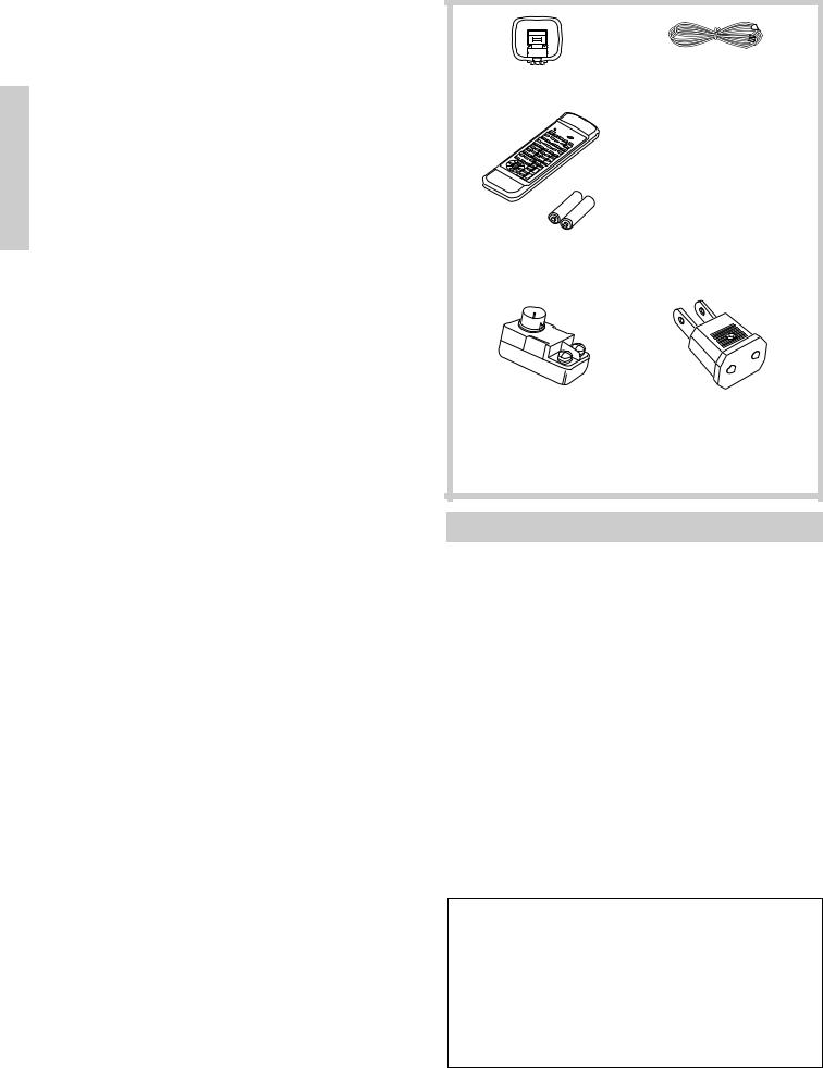
AM loop antenna (1) |
T-shaped FM antenna (1) |
Remote controller (RC-373M) (1)
Batteries (size AA, R6, or UM-3) (2)
75/300 ohm antenna |
Conversion plug (1) |
adapter (1) |
(Worldwide model only) |
(Except for USA and |
|
European models) |
|
Multi-Room Remote System (MRX)
By connecting the Multi-Room Remote System equipment, you can operate all components connected to the TX-DS656 from either the main room or the sub-room. (Refer to pages 46 to 48 for more details.) The following equipment (sold separately) is essential for using the Onkyo Multi-Room System:
U.S. & Canada:
•Onkyo's Multi-Room System kits HKT-600 or HKT-700 (IR Remote Control Extension System) and
•Xantech's Multi-Room System
Other areas:
•Sensor Unit: Model No. HR-10
•Remote Emitter: Model No. HE-50 (AC)
•Remote Emitter Head: Model No. HE-10
The following secondary remote controller can be used to operate the system from the sub-room:
• Secondary Remote Controller for Multi-Room Remote System: Model No. RC-MR1H
Consult your nearest Onkyo service center when replacing your Onkyo Multi-Room System with a Xantech Multi-Room System.
Memory Preservation
This unit does not require memory preservation batteries. A built-in memory power back-up system preserves the contents of the memory during power failures and even when the unit is unplugged. The unit must be plugged in order to charge the back-up system. The memory preservation period after the unit has been unplugged varies depending on climate and placement of the unit. On the average, memory contents are protected over a period of a few weeks after the last time the unit has been unplugged. This period is shorter when the unit is exposed to a highly humid climate.
4
Before using this unit
AM FREQUENCY |
|
STEP |
|
10kHz |
|
9kHz |
|
MJ 27122482 |
|
VOLTAGE SELECTOR |
|
220-230V |
120V |
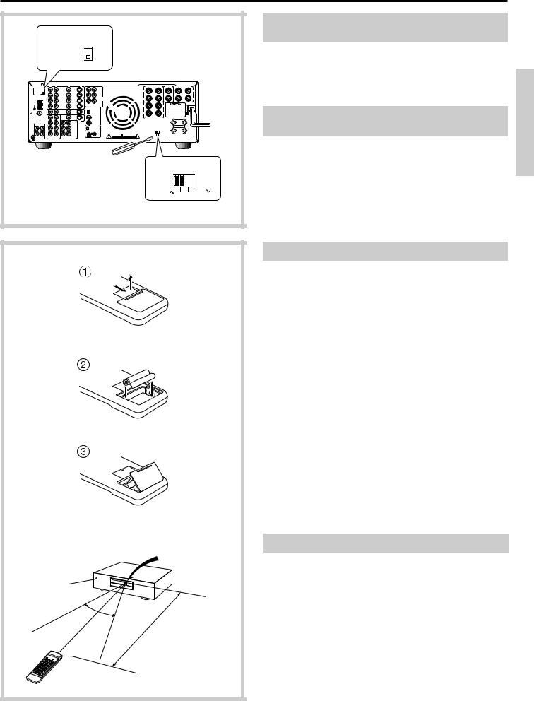
Setting the AM tuning step frequency (worldwide model only)
Worldwide models are equipped with a switch that controls the AM band tuning steps. Set this switch to match the AM band tuning step
frequency in your area. |
|
U.S.A. and Canada |
: 10kHz |
Other areas |
: 9kHz |
Setting the voltage selector (worldwide model only)
Worldwide models are equipped with a voltage selector to conform with local power supplies. Be sure to set this switch to match the voltage of the power supply in your area before plugging in the unit.
1.Determine the proper voltage for your area: 220-230V or 120V.
2.If the preset voltage is not correct for your area, insert a screwdriver into the groove in the switch. Slide the switch all the way to the right (120V) or to the left (220-230V), whichever is appropriate.
-
+
+
 -
-
+ -
TX-DS656
Remote control sensor
STAND-BY indicator
30˚  30˚
30˚
approx. 5m (16 feet)
RC-373M
Installing the batteries
1.Remove the battery compartment cover by pressing and sliding it out.
2.Insert two AA (R6 or UM-3)-size batteries into the battery compartment. Carefully follow the polarity diagram (positive (+) and negative (-) symbols) inside the battery compartment.
3.After batteries are installed and seated correctly, replace the compartment cover.
•If the battery voltage is low, the indicator on the remote controller does not flash when you press a button on the controller.
Remove low-voltage batteries immediately to avoid damage due to corrosion. Never mix old and new batteries.
•The learned codes are retained, even when the batteries are replaced.
They may be lost, however, if battery replacement is not completed within one hour. In this case, the unit must learn the codes again.
•The manganese batteries supplied with this unit have a service life of approximately six months, depending on the frequency of use.
•Use spare batteries of the type specified in the table below.
Type |
Voltage |
Size |
|
|
|
Manganese or |
1.5V |
AA, R6 (UM-3) or |
Alkaline |
|
LR6 (AM-3) |
|
|
|
We recommend that long-life AA (LR6 or AM-3)-size alkaline batteries be used.
Using the remote controller
The STAND-BY indicator lights up when the unit receives a signal from the remote controller.
The following information will help you get optimal use from the remote controller.
•Place this receiver away from direct bright light, which could prevent proper operation of the remote controller.
•Make sure audio rack doors do not have tinted glass. Placing the receiver behind such a door may prevent proper remote control.
•Using other remote controllers along with this receiver's remote controller in the same room may cause interference.
5
Connection
This section describes, step by step, how to connect the TX-DS656 to your home theater components.
1 |
Connecting analog audio source equipment |
page 8 |
2 |
Connecting digital audio source equipment |
page 8 |
3 |
Connecting video source equipment |
page 9 |
4 |
Connecting a video camera or TV game machine |
page 9 |
5 |
Connecting a decoder with 5.1-channel output |
page 10 |
6 |
Connecting video recording equipment |
page 10 |
7 |
Connecting audio recording equipment |
page 11 |
8 |
Connecting the z remote control cables |
page 11 |
9 |
Connecting a TV/monitor |
page 12 |
0 |
Connecting the antennas |
page 13 |
A Connecting speakers |
page 15 |
|
B Connecting power amplifiers |
Page 16 |
|
C Using the AC outlets |
Page 17 |
|
D Connecting the power |
Page 17 |
|
To connect source or recording equipment, use cables supplied by the equipment manufacturer.
Note:
•Do not turn on any component until you have completed all connections.
•Insert the plugs and connectors completely. Remember that improper connection may result in noise or malfunction.
•Do not bind audio connection cables with power cords and speaker cables. Doing so may degrade sound quality.
Improper connection
Insert the plugs and connectors securely. Remember that improper connection can result in noise, poor performance, or damage to the equipment.
Insert completely.
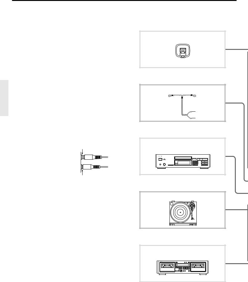
0 Connecting the antennas
AM loop antenna
0 Connecting the antennas
T-shaped FM antenna
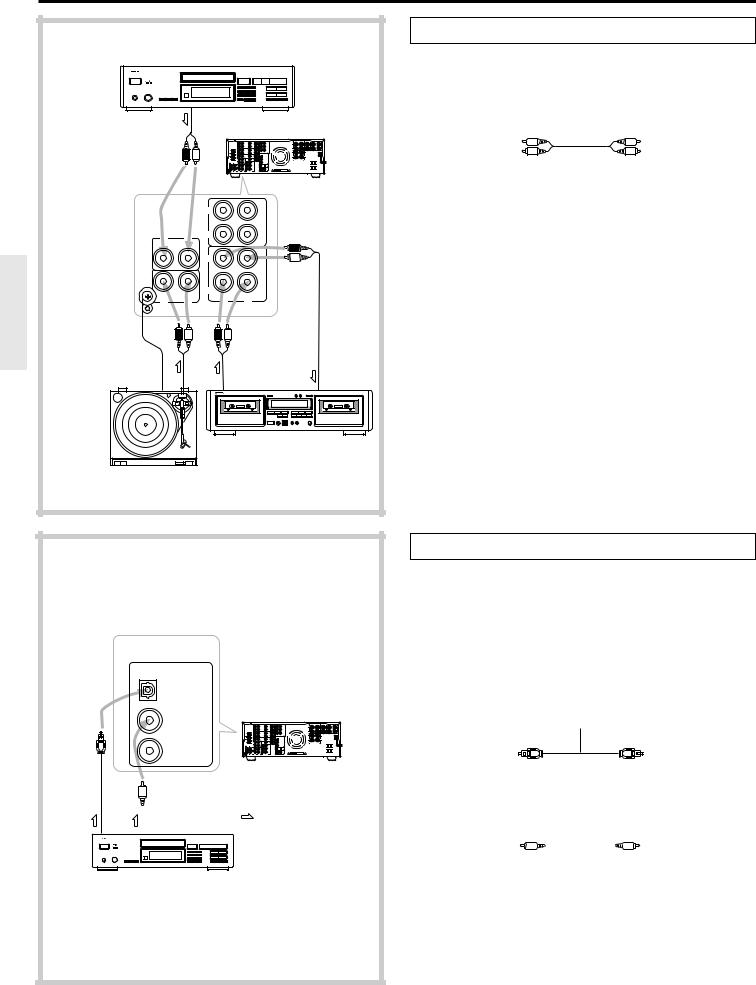
1 Connecting analog audio source equipment
CD player
1 Connecting analog audio source equipment
Turntable
1 Connecting analog audio source equipment
7 Connecting audio recording equipment
MD recorder, DAT deck, or cassette tape deck
6

3 Connecting video source equipment
6Connecting video recording equipment
Video cassette recorder
3Connecting video source equipment
DVD player
2Connecting digital audio source equipment
CD player, DAT deck or MD recorder
5Connecting a decoder with 5.1-channel output
Decoder with 5.1-ch output
A Connecting speakers
MJ
R |
L |
V |
S |
SURROUND SPEAKERS |
CENTER |
FRONT MAIN |
SPEAKERS |
SPEAKER |
|
OUT |
OUT |
FRONT |
|
|
|
|
|
|
VIDEO-1 |
R |
L |
|
|
|
|
|
ANTENNA |
IN |
IN |
SURROUND |
R |
L |
R |
L |
|
|
|
|
|
|||||
|
|
R |
L |
MULTI |
|
|
|
|
|
|
|
|
CHANNEL |
|
|
|
|
|
OUT |
OUT |
|
INPUT |
|
|
|
|
AM |
VIDEO-2 |
CENTER |
SUBWOOFER |
CAUTION: SPEAKER IMPEDANCE |
|
6 OHMS MIN. / SPEAKER |
|||
|
|
IN |
|
|
|
IN |
|
|
FM |
|
|
|
DIGITAL INPUT |
R |
L |
|
75 |
|
|
|
|
|
||
|
|
IN DVD |
|
IN |
DIGITAL 1 |
|
|
|
|
|
(OPTICAL) |
|
|
||
FM |
|
|
|
|
|
|
|
|
|
|
|
|
|
|
|
300 |
|
|
|
|
|
|
|
|
(REC) |
|
V |
MONITOR |
DIGITAL 2 |
FRONT REMOTE SPEAKERS |
|
|
|
OUTPUT |
(COAXIAL) |
||||
|
|
OUT |
|
||||
|
|
|
|
|
|
|
|
|
|
TAPE-1 |
|
S |
|
|
|
|
|
|
|
DIGITAL 3 |
|
|
|
R |
(PLAY) |
IN |
|
FRONT |
|
|
|
L |
|
|
|
(COAXIAL) |
|
|
|
|
CD |
R |
|
L |
|
|
AC OUTLETS |
|
|
|
|
|
|
|
|
|
(REC) |
|
|
SURROUND |
|
|
AC 120V 60Hz |
|
|
|
REMOTE CONTROL |
|
SWITCHED |
||
|
|
OUT R |
|
|
|
||
|
|
|
L |
IN |
|
TOTAL 120W 1A MAX. |
|
|
|
|
|
OUT |
|
|
|
GND |
|
IN |
|
|
WARNING |
AVIS |
|
|
(PLAY) |
|
|
|
|
||
PHONO |
|
TAPE-2 |
CENTER SUBWOOFER |
RISK OF ELECTRIC SHOCK |
RISQUE DE CHOC ELECTRIQUE |
|
R |
DO NOT OPEN |
NE PAS OUVRIR |
||||
R |
L |
L |
PRE OUT |
|
|
|
D Connecting the Power
8 Connecting the z remote |
C Using the AC outlets |
control cables |
|
9 Connecting a TV/monitor |
4 Connecting a video camera or TV game machine |
TV |
VIDEO-3/VIDEO CAM INPUT |
|
AV DIGITAL SURROUND AMPLIFIER |
A-DS656
B Connecting power amplifiers
7
Connection
CD player
OUT |
TX-DS656 |
(REC)
|
|
OUT |
|
|
TAPE-1 |
R |
(PLAY) |
IN |
L |
|
|
|
CD |
|
|
(REC) |
|
|
|
OUT |
GND |
|
IN |
(PLAY)
PHONO |
|
TAPE-2 |
|
R |
L |
R |
L |
 : Signal flow
OUT OUT |
IN |
MD recorder, DAT deck, or cassette tape deck
Turntable
1 Connecting analog audio source equipment
Connect your audio source equipment, such as a turntable, CD player, MD recorder, DAT deck, or cassette tape deck, as shown below.
|
Audio connection cable |
|||||
To source's Left |
|
|
|
To receiver's TAPE-1/ |
||
output jack |
|
|
|
TAPE-2 L IN (PLAY) |
||
|
|
|
||||
(White) |
|
|
|
|
|
(White) |
|
|
|
|
|
||
(Red) |
|
|
|
|
|
(Red) |
|
|
|
|
|
||
|
|
|
|
|
||
To source's Right |
|
|
|
To receiver's TAPE-1/ |
||
output jack |
|
|
|
TAPE-2 R IN (PLAY) |
||
If you have a 3-head cassette tape deck...
Connect it to the TAPE-2 IN jacks. This allows you to monitor the sound being recorded.
GND terminals
Connect the grounding wire of your turntable to one of these terminals. Use the other terminal as a spare. Do not leave the grounding wire connected if noise increases after connecting.
DIGITAL INPUT
DIGITAL 1 (OPTICAL)
TX-DS656
DIGITAL 2 (COAXIAL)
DIGITAL 3 (COAXIAL)
Optical |
Coaxial output |
: Signal flow |
|||||||||
output |
|||||||||||
|
|
|
|
|
|
|
|
|
|||
|
|
|
|
|
|
|
|
|
|
|
|
|
|
|
|
|
|
|
|
|
|
|
|
|
|
|
|
|
|
|
|
|
|
|
|
|
|
|
|
|
|
|
|
|
|
|
|
CD player, DAT deck or
MD recorder
2 Connecting digital audio source equipment
The TX-DS656 has three digital input terminals. Therefore, you can connect up to three digital audio sources, such as a CD player, MD recorder, or DAT deck, etc., using optical and coaxial cables.
Note:
Even if the digital source is connected via optical or coaxial cable, it also must be connected via audio connection cables. The TX-DS656 receives analog signals from input source equipment only during recording or when the Multi-source function is enabled.
• Source with optical digital output
Optical cable
To source's optical
To receiver's DIGITAL
output terminal
INPUT DIGITAL 1
(OPTICAL) terminal
• Source with coaxial digital output |
|
|
|
||||
|
|
Coaxial cable |
|
|
|
||
To source's coaxial |
|
|
|
To receiver's DIGITAL |
|||
|
|
|
|||||
|
|
|
INPUT DIGITAL 2 |
||||
output terminal |
|
|
|
|
|
|
(COAXIAL) or DIGITAL |
|
|
|
|
|
|
||
|
|
|
|
|
|
|
|
|
|
|
|
|
|
|
3 (COAXIAL) terminal |
Note:
•Remove the protective cap covering the DIGITAL-1 (OPTICAL) terminal before trying to make a connection. When this terminal is not in use, replace the protective cap.
•If you have an LD player with AC-3RF output, connect it via an AC-3RF demodulator to one of the TX-DS656's DIGITAL INPUT terminals.
8

Connection |
|
|
|
|
|
|
|
|
|
|
|
|
|
|
|
|
|
3 Connecting video source equipment |
|||
|
|
|
|
|
|
|
• |
With a DVD player, video disc player, etc., that is equipped with at least |
||
|
|
|
|
|
|
|
|
one digital audio output terminal, its audio output can be connected to the |
||
|
|
|
|
|
|
|
|
TX-DS656 via an optical or coaxial cable (see the previous page). In this |
||
|
|
|
|
|
|
|
|
case, for recording or using the Multi-source function, it is also necessary |
||
|
|
|
|
|
TX-DS656 |
|
|
that you connect the equipment via audio connection cables. |
||
|
|
|
|
|
|
|
• The VIDEO-1 and VIDEO-2 OUT jacks can be used to connect |
|||
|
|
|
|
|
|
|
|
recording equipment such as a video cassette recorder. |
||
|
|
|
|
|
|
|
• |
Video input signals to the TX-DS656 cannot be output back to the same or |
||
|
|
|
|
|
|
|
|
other equipment. In other words, the VIDEO-1 V OUT jack does not output |
||
|
|
|
|
|
|
|
|
signals which have been input to the TX-DS656 from its VIDEO-1 V IN jack. |
||
|
R |
L |
|
V |
S |
|
|
|
S-Video connection cable |
|
|
|
OUT |
|
|
OUT |
FRONT |
|
|
|
|
|
|
VIDEO-1 |
|
R |
L |
|
To source's S-Video |
To receiver's VIDEO- |
||
|
|
|
|
|
|
|||||
|
|
IN |
|
|
IN |
SURROUND |
||||
|
|
|
|
output jack |
|
1/2/3/DVD S IN jack |
||||
|
|
|
|
|
R |
L |
MULTI |
|
||
|
|
|
|
|
|
|
CHANNEL |
|
|
|
|
|
OUT |
|
|
OUT |
|
INPUT |
|
Video connection cable |
|
|
|
VIDEO-2 |
|
CENTER |
SUBWOOFER |
|
||||
|
|
IN |
|
|
IN |
|
|
|
|
|
|
|
IN |
DVD |
|
IN |
|
|
To source's Video |
(Yellow) |
(Yellow) To receiver's VIDEO- |
|
|
|
|
|
|
|
|
output jack |
|
1/2/3/DVD V IN jack |
|
|
|
|
|
|
|
To source's Left |
Audio connection cable |
||
|
|
|
|
|
|
|
|
To receiver's VIDEO- |
||
|
|
|
|
|
|
|
audio output jack |
|
1/2/3/DVD L IN jack |
|
|
|
|
|
|
|
|
|
(White) |
|
(White) |
|
|
|
|
|
|
|
|
(Red) |
|
(Red) |
IN |
OUT |
|
|
|
OUT |
|
To source's Right |
|
To receiver's VIDEO- |
|
|
|
|
|
|
|
|
audio output jack |
|
1/2/3/DVD R IN jack |
|
Video cassette recorder |
|
DVD player |
If you have connected a video source with an S-Video output |
|||||||
|
• The TX-DS656 does not convert S-video input signals into normal |
|||||||||
|
|
|
|
|
|
|
||||
|
: Signal flow |
|
|
|
|
|
|
video signals. That is, input signals to the VIDEO-1/2/3/DVD S IN |
||
|
|
|
|
|
|
|
jack will be output from the MONITOR OUTPUT S jack and the |
|||
|
|
|
|
|
|
|
|
|||
|
|
|
|
|
|
|
|
VIDEO-1/2 S OUT jack only. Similarly, input signals to the VIDEO- |
||
|
|
|
|
|
|
|
|
1/2/3/DVD V IN jack will be output from the MONITOR OUTPUT V |
||
|
|
|
|
|
|
|
|
jack and the VIDEO-1/2 V OUT jack only. |
||
|
|
|
|
|
|
|
• See the owner's manual of your video source equipment to determine |
|||
|
|
|
|
|
|
|
|
whether to connect it via normal video connection cables only or via |
||
|
|
|
|
|
|
|
|
both normal video and S-video connection cables. |
||
|
|
|
|
|
|
|
4 Connecting a video camera or TV game machine |
|||
|
|
|
|
|
TX-DS656 |
|
Connect your video camera or TV game machine to the VIDEO-3/ |
|||
|
|
|
|
|
|
|
||||
|
|
|
|
|
|
|
VIDEO CAM INPUT jacks. |
|
||
|
|
|
|
|
|
|
If a monaural video camera is used, connect its audio connection cable |
|||
|
|
|
|
|
|
|
to "R (MONO)" audio jack. |
|
||
VIDEO 3/VIDEO CAM INPUT
S VIDEO |
VIDEO |
L AUDIO R(MONO) |
: Signal flow
OUT
Video camera or TV game machine
9

Connection
TX-DS656
R |
L |
V |
S |
|
|
|
OUT |
|
OUT |
FRONT |
|
|
VIDEO-1 |
|
R |
L |
|
|
|
|
|
|
|
|
IN |
|
IN |
SURROUND |
|
|
|
|
R |
L |
MULTI |
|
|
|
|
|
CHANNEL |
|
OUT |
|
OUT |
|
INPUT |
|
VIDEO-2 |
|
CENTER |
SUBWOOFER |
|
|
|
|
|||
|
IN |
|
IN |
|
|
|
IN DVD |
|
IN |
|
|
OUT |
OUT |
 : Signal flow
Decoder with 5.1-ch output
TX-DS656
R |
L |
V |
S |
OUT |
OUT |
VIDEO-1 |
|
IN |
IN |
OUT |
OUT |
VIDEO-2 |
|
IN |
IN |
IN DVD |
IN |
IN OUT
Video cassette recorder
 : Signal flow
5 Connecting a decoder with 5.1-channel output
The TX-DS656's MULTI CHANNEL INPUT jacks can be used to connect a decoder equipped with 5.1-ch audio output (dts decoder, MPEG decoder, etc.). If you do so, use the V or S IN jack of the VIDEO-1/2/3 or DVD connector to connect the video or S-video connection cable.
To decoder's |
Audio connection cable |
|
||||
|
|
|
|
To receiver's MULTI |
||
multi-channel output |
|
|
|
|
CHANNEL INPUT L |
|
Left front jack (White) |
|
|
|
|
(White) |
FRONT jack |
|
|
|
|
|||
(Red) |
|
|
|
|
(Red) |
|
|
|
|
|
|
||
To decoder's |
|
|
|
|
To receiver's MULTI |
|
multi-channel output |
|
|
|
|
CHANNEL INPUT R |
|
Right front jack |
|
|
|
|
|
FRONT jack |
To decoder's multi- |
Audio connection cable |
||||||
|
|
|
|
|
|
To receiver's MULTI |
|
channel output Left |
|
|
|
|
|
|
CHANNEL INPUT L |
surround jack (White) |
|
|
|
|
|
|
(White) SURROUND jack |
|
|
|
|
|
|
||
(Red) |
|
|
|
|
|
|
(Red) |
|
|
|
|
|
|
||
To decoder's multi- |
|
|
|
|
|
|
To receiver's MULTI |
channel output Right |
|
|
|
|
|
|
CHANNEL INPUT R |
surround jack |
|
|
|
|
|
|
SURROUND jack |
|
Monaural audio cable |
||||||
To decoder's |
|
|
|
|
|
|
To receiver's MULTI |
|
|
|
|
|
|
||
multi-channel output |
|
|
|
|
|
|
CHANNEL INPUT |
|
|
|
|
|
|
||
Subwoofer jack |
|
|
|
|
|
|
SUBWOOFER jack |
|
Monaural audio cable |
||||||
To decoder's |
|
|
|
|
|
|
To receiver's MULTI |
|
|
|
|
|
|
||
multi-channel output |
|
|
|
|
|
|
CHANNEL INPUT |
|
|
|
|
|
|
||
Center jack |
|
|
|
|
|
|
CENTER jack |
Note:
The Surround function cannot be used if audio signals are input from the MULTI CHANNEL INPUT connector.
6 Connecting video recording equipment
Connect your video cassette recorder to the VIDEO-1/VIDEO-2 OUT jacks.
S-Video connection cable
To source's S-Video |
To receiver's VIDEO- |
input jack |
1/2 S OUT jack |
Video connection cable |
|
To source's Video (Yellow) |
(Yellow) To receiver's VIDEO- |
input jack |
1/2 V OUT jack |
Audio connection cable |
|
To source's Left |
To receiver's VIDEO- |
audio input jack |
1/2 L OUT jack |
(White) |
(White) |
(Red) |
(Red) |
To source's Right |
To receiver's VIDEO- |
audio input jack |
1/2 R OUT jack |
Note:
When you connect a VCR, etc. to the VIDEO-2 R/L jacks, you must turn the IPM function off. (See page 12.)
10
Connection
TX-DS656
(REC)
|
OUT |
|
TAPE-1 |
(PLAY) |
IN |
(REC) |
|
|
OUT |
|
IN |
(PLAY) |
TAPE-2 |
|
|
R |
L |
OUT 
 IN
IN
 : Signal flow
MD recorder, DAT or cassette tape deck
TX-DS656
|
|
: Signal flow |
|
(REC) |
|
|
|
|
OUT |
|
|
|
TAPE-1 |
Graphic equalizer |
|
(PLAY) |
IN |
|
|
(REC) |
|
|
|
|
OUT |
OUT |
IN |
|
|
||
|
IN |
|
|
(PLAY)
TAPE-2
R L
7 Connecting audio recording equipment
Connect your audio recording equipment to the TAPE-1/2 OUT (REC) jacks.
Digital recording is not possible, even if a DAT deck or MD recorder is connected.
To source's Left |
Audio connection cable |
||||||
|
|
|
|
|
|
To receiver's TAPE- |
|
audio input jack |
|
|
|
|
|
|
1/2 OUT (REC) |
(White) |
|
|
|
|
|
|
(White) |
|
|
|
|
|
|||
(Red) |
|
|
|
|
|
|
(Red) |
|
|
|
|
|
|
||
To source's Right |
|
|
|
|
|
|
To receiver's TAPE- |
audio input jack |
|
|
|
|
|
|
1/2 OUT (REC) |
If you have a 3-head cassette tape deck
Connect it to the TAPE-2 IN jacks. This allows you to monitor the sound being recorded.
If you have a graphic equalizer
Connect the graphic equalizer to the TAPE-2 IN jacks and the recorder to the equalizer. If you do so, you can use the TAPE-2 Monitor function to monitor the sound processed by the equalizer during recording.
CAUTION:
Do not select a Surround mode when using the equalizer. This will result in distortion and possible damage to the Surround decoder circuitry.
REMOTE CONTROL
CD player
Cassette tape deck
DVD player
8 Connecting the z remote control cables
An Onkyo cassette tape deck, CD player or DVD player equipped with an z jack can be connected to the TX-DS656 via the remote control cable supplied with the unit. Once connected, it can be operated by using the receiver's remote controller.
Note:
•Connect the remote control cable to the black jack with the z mark; never connect it to the jack with the  mark.
mark.
•For playback and recording, the unit also must be connected via audio connection cables.
•Do not use the z REMOTE CONTROL jack to connect products not bearing z symbol. Doing so may result in the failure of the equipment.
•You cannot operate turntables and MD recorders by remote controller even if they are Onkyo z compatible.
11

Connection
TX-DS656
VMONITOR OUTPUT
S
: Signal flow
IN
|
TV |
|
|
|
|
1 |
TV |
|
|
TX-DS656 |
|
|
|
|
|
|
|
|
R |
L |
|
V |
S |
|
|
OUT |
|
OUT |
|
|
|
VIDEO-1 |
|
|
|
IN |
OUT |
IN |
|
IN |
|
|
|
|
|
||
|
|
OUT |
|
OUT |
|
|
|
VIDEO-2 |
|
||
|
|
IN |
|
IN |
|
|
|
IN |
DVD |
IN |
|
|
|
V |
|
MONITOR |
|
: Signal flow |
|
OUTPUT |
|
||
|
|
|
|||
|
|
|
|
||
|
|
|
|
S |
|
3 |
|
|
|
|
|
VIDEO-2 |
|
|
|
|
IPM |
VCR-2 / TV |
|
|
|
|
|
|
|
|
|
|
|
4 |
|
|
|
|
|
SMART SCAN CONTROLLER |
|
|
|
|
|
|
|
|
|
|
IPM |
12 |
|
|
|
|
|
9 Connecting a TV/monitor
A TV or monitor equipped with a video input jack can be connected to the TX-DS656.
S-Video connection cable
To TV's S-Video |
To receiver's MONITOR |
input jack |
OUTPUT S jack |
Video connection cable |
|
To TV's Video input (Yellow) |
(Yellow)To receiver's MONITOR |
jack |
OUTPUT V jack |
Note:
If distortion of the TV image occurs or if noise is output from the unit, place the unit and the TV as far apart as possible.
Turning the unit on/off with the TV's power switch – IPM function
The TX-DS656 is equipped with the IPM (Intelligent Power Management) system.
Just turn on your TV's power switch and, in about 5 seconds, the TXDS656 turns on automatically. If you turn off the TV's power switch, "." flashes on the display and the TX-DS656 automatically turns off in about 5 minutes.
To activate the IPM function...
1.Connect the audio output of your TV to the TX-DS656's VIDEO-2 L and R IN jacks.
If a monaural TV is used, connect the TV's audio output to the TXDS656's VIDEO-2 L IN jack.
2.Press the VIDEO-2 VCR-2/TV button on the front panel.
"VIDEO-2 VCR" or "VIDEO-2 TV" appears on the display.
3.Press the VIDEO-2 VCR/TV button repeatedly until "IPM OFF (or IPM ON, if the function is already activated)" appears on the display.
4.Rotate the SMART SCAN CONTROLLER to select "IPM ON".
•The IPM function is activated and, after 3 seconds, the display changes to "VIDEO-2 TV".
•If you select "IPM OFF", the display will change to "VIDEO-2 VCR" after 3 seconds.
Note:
•The IPM system may not function properly with some TV sets.
•When the IPM system is activated, the video input signals to the VIDEO-2 V IN jack are not output from the MONITOR OUTPUT V jack.
•Setting a digital input mode for the VIDEO-2 input source automatically turns off the IPM function. You cannot turn on the TXDS656 automatically.
•The IPM function cannot be used when the MULTI-CH INPUT source is selected.
CAUTION:
If you have connected the TV's video output and video input to the TXDS656's VIDEO-2 V IN and MONITOR OUTPUT V jacks,be sure to turn ON the IPM function. Otherwise, the signals will loop in the circuit, causing damage to the unit.
Connection |
|
|
|
|
|
|
|
|
|
|
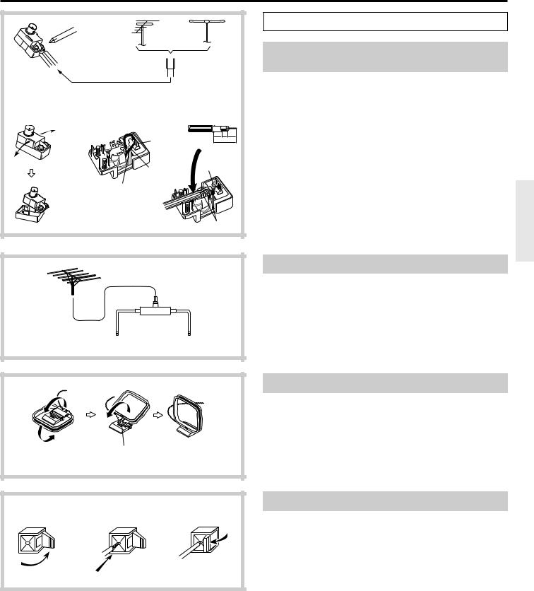
Indoor |
0 Connecting the antennas |
|||
|
|
Outdoor |
|
||||
|
|
antenna |
|
||||
|
|
antenna |
|
||||
|
|
|
|
|
|
Connecting the antenna cable to the 75/300 ohm |
|
|
|
|
|
|
|
|
|
|
|
|
300 ohms |
|
|
antenna adapter (worldwide models) |
|
|
|
|
ribbon wire |
|
Connecting a 300 ohm ribbon wire to the 75/300 ohm adapter: |
||
|
|
|
|
|
|
|
|
|
|
|
|
|
|
|
Loosen the screws and wrap the wire around them. Tighten the screws |
1 |
2 |
|
3 |
|
|
|
with a screwdriver. |
|
|
|
|
Connecting a coaxial : |
|||
|
|
|
|
|
1. With your fingernail or a small screwdriver, press the stoppers |
||
|
|
|
|
|
|
|
|
|
|
|
|
|
|
|
|
|
|
|
|
|
|
|
|
|
|
|
|
6 |
3 |
6 |
outward and remove the cover. |
|
|
Slit B |
|
mm mm mm |
|||
|
|
|
15mm |
2. Remove the transformer wire A from slit B and insert it into slit C. |
|||
|
|
|
|
||||
|
|
|
|
|
|
|
|
|
|
|
|
|
|
|
3. Prepare the coaxial cable as shown in the diagram. |
|
|
Wire A |
1 |
|
|
|
Connect the 75/300 ohm antenna adapter to the coaxial cable. |
|
|
|
|
|
|
||
|
|
|
|
|
|
|
1 Insert the end of the cable. |
|
|
Slit C |
|
|
|
|
2 Clamp it in place with pliers. |
|
|
|
|
|
|
|
4. Re-install the cover. |
|
|
|
|
|
|
|
• This adapter is included if your receiver is a worldwide model. |
|
|
|
|
2 |
|
|
|
Directional linkagetype splitter
To TX-DS656 |
To TV (or VCR) |
Directional linkage
Do not use the same antenna for both FM and TV (or VCR) reception since the FM and TV (or VCR) signals can interfere with each other. If you must use a common FM/TV (or VCR) antenna, use a directional linkage-type splitter.
Assembling the AM loop antenna
Assemble the loop antenna as shown in the illustration.
Insert into the hole.
1 |
2 |
3 |
Connecting the antenna cable |
|
1. |
Press down on the lever. |
|||
|
|
|
2. |
Insert the wire. |
|
|
|
3. |
Return the lever. |
13

Connection
U.S. and Canadian models |
Other models |
ANTENNA
ANTENNA
AM
AM
FM 75 
FM 75Ω
FM 300Ω
ANTENNA
AM
FM 75
U.S. and Canadian models |
Other models |
ANTENNA
ANTENNA
AM
AM
FM 75Ω
FM 300Ω
FM 75Ω
Connecting the included antennas
Connecting the T-shaped FM antenna:
The T-shaped FM antenna is for indoor use only. Extend the antenna and move it in various directions until the clearest signal is received. Fix it with push pins or similar implements in the position that will cause the least amount of distortion.
If the reception is not very clear with the attached T-shaped FM antenna, the use of an outdoor antenna is recommended.
Connecting the AM loop antenna:
The AM loop antenna is for indoor use only. Set it in the direction and position where you receive the clearest sound. Put it as far away as possible from the unit, TVs, speaker cables,
and power cords.
When reception is not satisfactory with the attached AM loop antenna alone, connection of an outdoor antenna is recommended.
U.S. and Canadian models |
Other models |
ANTENNA |
|
|
ANTENNA |
AM |
|
FM |
AM |
75Ω |
|
FM |
|
300Ω |
|
|
FM |
|
75Ω |
Connecting an FM outdoor antenna
Please make sure that you follow the considerations below regarding the location.
Keep the antenna away from noise sources (neon signs, busy roads, etc.). It is dangerous to put the antenna close to power lines. Keep it well away from power lines, transformers, etc.
• To avoid the risk of lightning and electrical shock, grounding is necessary. Follow item 19 of the “Important Safeguards” on page 2 when you install the outdoor antenna.
U.S. and Canadian models |
Other models |
|
ANTENNA |
ANTENNA |
|
AM |
AM |
|
FM 75Ω
FM
FM  75Ω 300Ω
Connecting an AM outdoor antenna
The outdoor antenna will be more effective if it is stretched horizontally above a window or outside.
•Do not remove the AM loop antenna.
•To avoid the risk of lightning and electrical shock, grounding is necessary. Follow item 19 of the “Important Safeguards” on page 2 when you install the outdoor antenna.
14
Connection
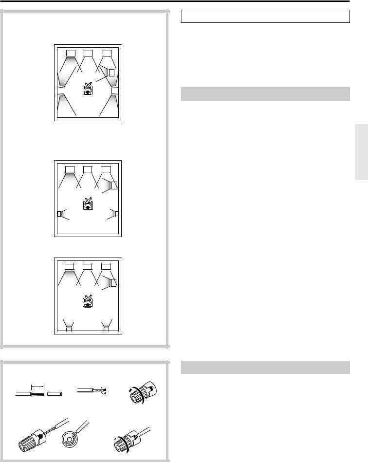
If bipolar type speakers are connected to the surround channels
(Left front) |
(Center) |
(Right front) |
L |
C |
R |
|
|
SW |
|
|
(Subwoofer) |
LS |
|
RS |
(Left Surround) |
|
(Right Surround) |
If other speakers are connected to the surround channels
|
(Left front) |
(Center) |
(Right front) |
|
L |
C |
R |
|
|
|
SW |
|
|
|
(Subwoofer) |
|
LS |
|
RS |
|
(Left Surround) |
|
(Right Surround) |
|
(Left front) |
(Center) |
(Right front) |
|
L |
C |
R |
|
|
|
SW |
|
|
|
(Subwoofer) |
|
LS |
|
RS |
|
(Left Surround) |
|
(Right Surround) |
1 |
2 |
|
3 |
|
15mm |
|
|
|
4 |
|
5 |
A Connecting speakers
On the rear panel of the TX-DS656, two sets of speaker terminals are provided; one for main-room speakers and the other for sub-room speakers. This section provides information on connecting the mainroom speakers.
•For how to connect sub-room speakers, see "Multi-room system connections" on pages 46, 47.
•For how to set speakers, see "Speaker system setup" on pages 21-24.
Speaker placement
In this section, only typical examples of speaker placement are shown. Note, however, that ideal speaker placement varies depending on the size of the room and the wall coverings used in the room.
To obtain ideal sound field effects, the Left and Right front speakers must be placed at the same distance from the listening position.
Recommendations
•Left and Right front speakers (L/R) and Center speaker (C)
-Place these three speakers at the same height from the floor.
-Place each speaker so that sound is aimed at the audience's ears at the listening position.
•Left and Right Surround speakers (LS/RS)
Place these speakers so that their height is 1 meter higher than that of the audience's ears.
• Subwoofer (SW)
Place it anywhere in your listening room because the placement of the Subwoofer affects the perceived direction of the sound very little.
If your speaker system lacks Subwoofer, Center speaker, or Surround speakers
To get the highest-quality surround sound, you need a complete speaker system as shown. Even so, you can enjoy quality surround sound by setting up the speakers (see pages 25-28) so that the sound originally allocated to non-existing speakers is properly distributed to the existing Left and Right front speakers.
Connecting the speaker cables
1.Peel the ends of the speaker cable 15 mm. Do not cut core wires.
2.Twist the core wires.
3.Loosen the cap on the speaker binding post by turning it counterclockwise.
4.Insert the core wires into the binding post.
5.Fasten the cap on the binding post by turning it clockwise.
When using banana plugs, be sure to tighten the speaker connector screws firmly before inserting the banana plugs.
• Note that the speaker connectors on the European and some other models are not banana-plug compatible.
15
Connection |
|
|
|
|
|
|
|
|
|
|
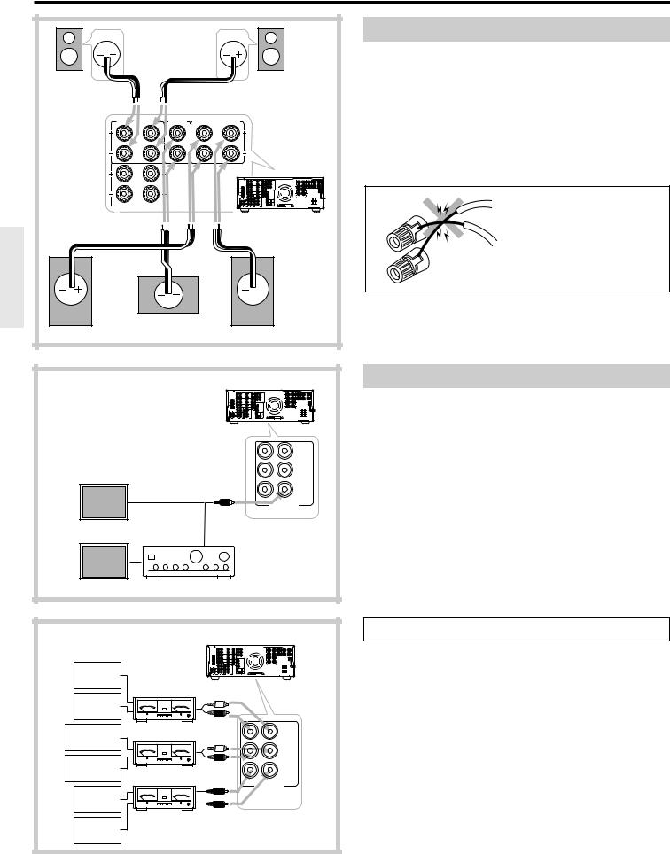
Connection for Front, Center, and Surround speakers |
|
|
|
|
|
Note: |
|
|
|
|
|
• Be sure to connect the Right and Left speakers to the receiver's |
Right |
|
|
|
Left |
corresponding speaker terminals. Also, be sure that you are connecting |
Surround |
|
|
|
Surround |
the speaker's positive (+) and negative (-) binding posts with the |
speaker |
|
|
|
speaker |
|
|
|
|
receiver's corresponding speaker terminals. Otherwise,inferior sound |
||
|
|
|
|
|
|
SURROUND SPEAKERS |
CENTER |
FRONT MAIN SPEAKERS |
will result. |
||
SPEAKER |
|||||
|
|
|
|
|
• Use speakers whose nominal impedance is 6Ω. Connecting a speaker |
R |
L |
|
R |
L |
whose impedance is less than 6Ω may cause damage to the receiver. |
|
|
|
|
|
|
|
|
|
|
|
• Do not connect two or more speaker cables to the same speaker |
|
|
|
|
|
terminal. Doing so may cause damage to the receiver. |
R |
L |
|
|
|
|
FRONT REMOTE SPEAKERS |
|
|
|
Warning: |
|
|
|
|
|
TX-DS656 |
|
|
|
|
|
To prevent damage to circuitry, |
|
|
|
|
|
|
never short-circuit the positive (+) |
|
|
|
|
|
and negative (-) speaker wires by |
Right |
|
|
|
Left |
allowing them to touch each other. |
|
|
|
|
||
front |
|
|
|
front |
|
speaker |
|
|
|
speaker |
|
|
Center speaker |
|
|
||
|
|
|
|
TX-DS656 |
Connecting a subwoofer |
|
|
|
|
|
|
|
|
|
|
|
Use the PREOUT SUBWOOFER jack to connect a subwoofer with a |
|
|
|
|
|
built-in power amplifier. If your subwoofer does not have a built-in |
|
|
|
|
|
amplifier, connect an amplifier to the PREOUT SUBWOOFER jack |
|
|
|
|
|
and the subwoofer to the amplifier. |
|
|
|
|
FRONT |
|
Subwoofer with built-in amplifier |
R |
L |
|
SURROUND |
|
(Active subwoofer) |
|
|
R |
L |
CENTER SUBWOOFER
PRE OUT
Subwoofer without amplifier
Amplifier
|
|
TX-DS656 |
B Connecting power amplifiers |
|
|
|
|
||
|
|
|
|
Using auxiliary power amplifiers allows you to listen at louder volumes |
Left front |
|
|
|
than with the TX-DS656 alone. If power amplifiers are used, connect |
|
|
|
each speaker to the corresponding power amplifier. |
|
speaker |
|
|
|
|
|
Power amplifier |
|
|
|
Right front |
|
|
|
|
speaker |
|
|
|
|
Left Surround |
Power amplifier |
|
FRONT |
|
speaker |
R |
L |
|
|
|
|
|||
|
|
|
|
|
|
|
|
SURROUND |
|
Right Surround |
|
R |
L |
|
|
|
|
|
|
speaker |
Power amplifier |
|
|
|
|
CENTER SUBWOOFER |
|
||
Center |
|
|
PRE OUT |
|
|
|
|
|
|
speaker |
|
|
|
|
Subwoofer |
|
|
|
|
16

R |
L |
V |
MJ |
|
CENTER |
|
|
S |
SURROUND SPEAKERS |
SPEAKER |
FRONT MAIN |
SPEAKERS |
VIDEO-1 |
R |
L |
|
|
|
ANTENNA |
|
R |
L |
R |
L |
RL MULTI CHANNEL
INPUT
VIDEO-2 |
CAUTION: SPEAKER IMPEDANCE |
DIGITAL INPUT
R |
L |
DVD |
|
V |
FRONT REMOTE SPEAKERS |
|
TAPE-1 |
|
S |
R |
L |
|
|
CD |
R |
L |
AC OUTLETS |
R L
GND
WARNING AVIS
PHONO |
|
TAPE-2 |
PRE OUT |
|
R |
L |
R |
L |
|
Other than U.S. and
U.S. and Canadian
Canadian models
models
Capacity is total 100 watts.
Capacity is total 120 watts.
STAND-BY indicator |
|
POWER button |
Display |
|
|
|
To wall |
|
outlet |
C Using the AC outlets
You can connect the power cord from other audio device to the rear of the TX-DS656. Since the AC outlets on the unit are the SWITCHED type, you can use the POWER button (or the SYSTEM button), or the POWER button on the remote controller to turn on/off the power to both the TX-DS656 and the connected audio devices.
Note: If your TX-DS656 has a POWER switch, first turn it on.
The shape, number, and total capacity of the AC outlets may differ depending on the area of purchase. Make sure that the total capacity of other components connected to this unit does not exceed the capacity that is printed on the rear panel.
D Connecting the power
•Before plugging in the receiver, confirm that all connections have been made properly.
•Before turning on the power, make sure that the MASTER VOLUME control is fully turned counterclockwise.
•Turning on this receiver’s power may cause a momentary power surge, which might interfere with other electrical equipment, such as computers. If so, use a wall outlet on a different circuit.
U.S. and Canadian models
1.Plug the power cord into an AC wall outlet.
The STAND-BY indicator lights up and the receiver enters stand-by mode, ready for operation.
2.Press the POWER button to turn on the receiver. The display will light up and the STAND-BY indicator will be turned off.
If you press the POWER button again, the receiver returns to stand-by mode.
•The POWER button on the remote controller is used in the same way as the POWER button on the TX-DS656.
STAND-BY indicator |
|
SYSTEM button |
|
POWER switch |
Display |
|
|
|
To wall |
|
outlet |
Other than U.S. or Canadian models
1.Plug the power cord into an AC wall outlet.
2.Press the POWER switch to set the receiver to stand-by mode.
The STAND-BY indicator will light up.
3.Press the SYSTEM button or POWER button on the remote controller to turn on the receiver. The display will light up and the STAND-BY indicator will be turned off.
If you press the SYSTEM button or POWER button on the remote controller again, the receiver turns to stand-by mode.
•You cannot use the remote controller if the POWER switch on the receiver is set to OFF.
17
 Loading...