


AV RECEIVER
TX-RZ730
Instruction Manual
En
Table of contents |
|
|
Connections |
|
|
- Connecting Speakers |
|
|
Playback |
|
|
Setup |
|
|
Troubleshooting |
|
|
Appendix |
|
|
Supplementary Information |
|
|
Front Panel Rear Panel Remote |
|
|
|
|
Contents Connections Playback Setup
What’s in the box |
5 |
Part Names |
6 |
Front Panel |
6 |
Display |
8 |
Rear Panel |
9 |
Remote Controller |
11 |
Connections |
|
|
|
Connecting speakers |
13 |
Speaker Installation |
14 |
Speaker Connections and "Speaker Setup" Settings |
40 |
Connecting a Power Amplifier |
57 |
Speaker combinations |
58 |
Connecting the TV |
59 |
To ARC TV |
60 |
To Non-ARC TV |
61 |
Connecting Playback Devices |
62 |
Connecting an AV Component with HDMI Jack |
|
Mounted |
62 |
Connecting an AV Component without HDMI Jack |
|
Mounted |
63 |
Connecting an Audio Component |
64 |
Connecting a Video Camera, etc. |
65 |
Connecting an AV Component in a Separate Room |
|
(Multi-zone Connection) |
66 |
Connecting a TV (ZONE 2) |
66 |
Connecting a Pre-main Amplifier (ZONE 2) |
67 |
Connecting a Pre-main Amplifier (ZONE 3) |
68 |
Connecting Antennas |
69 |
Network Connection |
70 |
Connecting External Control Devices |
71 |
IR IN port |
71 |
12V TRIGGER OUT jack |
72 |
Connecting the Power Cord |
73 |
Playback |
|
|
|
AV Component Playback |
75 |
Basic Operations |
75 |
BLUETOOTH® Playback |
76 |
Basic Operations |
76 |
Internet Radio |
77 |
Playing Back |
77 |
Spotify |
79 |
Playing Back |
79 |
AirPlay® |
80 |
Basic Operations |
80 |
DTS Play-Fi® |
81 |
2 |
Front Panel Rear Panel Remote |
|

Contents Connections Playback Setup
Playing Back
FlareConnectTM
Playing Back
USB Storage Device
Basic Operations
Device and Supported Format
Playing back files on a PC and NAS (Music Server)
Windows Media® Player settings
Playing Back
Supported Audio Formats
Play Queue
Initial Setup
Adding Play Queue Information
Sort and Delete
Playing Back
Listening To the AM/FM Radio
Tuning into a Radio Station
Presetting a Radio Station
Using RDS (European, Australian and Asian models)
Multi-zone
Switch remote control mode (ZONE 2)
Switch remote control mode (ZONE 3)
Playing Back
81Convenience functions
82Adjusting the tone
82Listening Mode
83Selecting a Listening mode
83 |
Listening Mode Effects |
85Selectable listening modes
86Setup
86 |
Setup Menu |
||
87 |
|||
90 |
Menu list |
||
Menu operations |
|||
91 |
|||
1. |
Input/Output Assign |
||
91 |
|||
2. |
Speaker |
||
91 |
|||
3. Audio Adjust |
|||
92 |
|||
4. |
Source |
||
92 |
|||
5. |
Hardware |
||
93 |
|||
6. |
Multi Zone |
||
93 |
|||
7. |
Miscellaneous |
||
95 |
|||
Quick Menu |
|||
97 |
|||
98 |
Menu operations |
||
99 |
Web Setup |
|
Menu operations |
||
100 |
||
Firmware Update |
||
101 |
||
|
3 |
Front Panel Rear Panel Remote |
|
103
103
104
104
106
111
124
124
126
127
131
137
138
140
145
146
147
147
149
149
150

|
|
Contents Connections Playback Setup |
|
|
|
|
|
|
|
|
|
|
Updating Function on This Unit |
150 |
|
|
Updating the Firmware via Network |
151 |
|
|
Updating via USB |
153 |
|
Initial Setup with Auto Start-up Wizard |
155 |
|
|
|
Operations |
155 |
|
|
Troubleshooting |
|
|
|
|
|
|
|
When the unit is operating erratically |
159 |
|
|
Troubleshooting |
160 |
|
|
Appendix |
|
|
|
|
|
|
About HDMI |
169 |
|
|
General Specifications |
171 |
|
|
4 |
Front Panel Rear Panel Remote |
|

Contents Connections Playback Setup
What’s in the box
2 3
4  5
5
6
1.Main unit (1)
2.Remote controller (RC-911R) (1), Batteries (AAA/R03) (2)
3.Speaker setup microphone (1)
•Used during Initial Setup.
4.Indoor FM antenna (1)
5.AM loop antenna (1)
6.Power cord (1)
•Quick Start Guide (1)
*This document is an online instruction manual. It is not included as an accessory.
•Connect speakers with an impedance of 4 Ω to 16 Ω.
•The power cord must be connected only after all other connections are completed.
•We will not accept any responsibility for damage arising from the connection with equipment manufactured by other companies.
•Network services and content that can be used may no longer be available if new functions are added by updating firmware or the service providers
terminate their services. Also, available services may differ depending on your area.
•Details on the firmware update will be posted on our website and through other means at a later date.
•Specifications and appearance are subject to change without prior notice.
5 |
Front Panel Rear Panel Remote |
|

Contents Connections Playback Setup
Part Names
Front Panel
1 |
2 3456 |
7 |
8 9 bk |
bl |
||||||||||
|
|
|
|
|
|
|
|
|
|
|
|
|
|
|
|
|
|
|
|
|
|
|
|
|
|
|
|
|
|
|
|
|
|
|
|
|
|
|
|
|
|
|
|
|
|
|
|
|
|
|
|
|
|
|
|
|
|
|
|
|
|
|
|
|
|
|
|
|
|
|
|
|
|
|
|
|
|
|
|
|
|
|
|
|
|
|
|
|
|
|
|
|
|
|
|
|
|
|
|
|
|
|
|
|
|
|
|
|
|
|
|
|
|
|
|
|
|
|
|
|
|
|
|
|
|
|
|
|
|
|
|
|
|
|
bm |
bn |
bo |
bp |
bq |
br |
For details, see (  p7)
p7)
6 |
Front Panel Rear Panel Remote |

Contents Connections Playback Setup
1. ON/STANDBY button
2.MUSIC OPTIMIZER button/indicator (North American models): Turns on/off the MUSIC OPTIMIZER function that improves the quality of the compressed audio.
PURE AUDIO button/indicator (European, Australian and Asian models): Switches to the Pure Audio mode. (  p108)
p108)
3.HYBRID STANDBY indicator: Lights if the unit enters standby mode when the functions such as HDMI Standby Through and Network Standby that work in standby are enabled.
4.Remote control sensor: Receives signals from the remote controller.
•The reception range of the remote controller is within a distance of approx.
16´/5 m, and an angle of 20° in vertical direction and 30° to right and left.
5.ZONE 2/ZONE 3 button: Controls the multi-zone function. (  p101)
p101)
6.DIMMER button: Switches the brightness of the display with three levels. It cannot be turned off completely.
7.Display (  p8)
p8)
8.SETUP button: You can display advanced setting items on the TV and the display to have a more enjoyable experience with this unit. (  p124)
p124)
9.Cursor buttons ( /
/  /
/  /
/  ) and ENTER button: Select an item with the cursors, and press ENTER to confirm your selection. When using TUNER, use them to tune in to stations. (
  p93)
p93)
10.RETURN button: Returns the display to the previous state while setting.
11.MASTER VOLUME
12.Press the LISTENING MODE button (above) to select a category from "Movie/ TV", "Music" and "Game", and then turn the LISTENING MODE dial (below) to change the listening mode. (  p104)
p104)
13.You can adjust the sound quality of the speakers. Press the TONE button (above) to select an item to adjust from "Bass" and "Treble", and turn the TONE dial (below) to adjust. (  p103)
p103)
14.PHONES jack: Connect headphones with a standard plug (ø1/4"/6.3 mm).
15.Input selector buttons: Switches the input to be played.
16.SETUP MIC jack: Connect the supplied speaker setup microphone. (  p156)
p156)
17.AUX INPUT AUDIO/HDMI jack: Connect a video camera, etc. using a stereo mini plug cable (ø1/8″/3.5 mm) or HDMI cable. (  p65)
p65)
7 |
Front Panel Rear Panel Remote |

Contents Connections Playback Setup
Display
1 |
2 |
|
3 |
4 |
5 |
|||||||||||
|
|
|
|
|
|
|
|
|
|
|
|
|
|
|
|
|
|
|
|
|
|
|
|
|
|
|
|
|
|
|
|
|
|
|
|
|
|
|
|
|
|
|
|
|
|
|
|
|
|
|
|
|
|
|
|
|
|
|
|
|
|
|
|
|
|
|
|
|
|
|
|
|
|
|
|
|
|
|
|
|
|
|
|
|
7 |
6 |
7 |
1.Speaker/Channel display: Displays the output channel that corresponds to the selected listening mode.
2.Lights in the following conditions.
 : Headphones are connected. Z2/Z3: ZONE 2/ZONE 3 is on.
 : Connected by BLUETOOTH.
 : Connected by Wi-Fi.
NET: Lights when connected to the network with the "NET" input selector. It will blink if incorrectly connected to the network.
USB: Lights when the "NET" input selector is selected, a USB device is connected and the USB input is selected. It will blink if the USB device is not properly connected.
HDMI: HDMI signals are input and the HDMI input is selected. DIGITAL: Digital signals are input and the digital input is selected.
3.Lights according to the type of input digital audio signal and the listening mode.
4.Lights in the following conditions.
RDS (European, Australian and Asian models): Receiving RDS broadcasting. TUNED: Receiving AM/FM radio.
FM ST: Receiving FM stereo. SLEEP: Sleep timer is set. (  p143)
p143)
AUTO STBY: Auto Standby is set. (  p143)
p143)
5.Blinks when muting is on.
6.Displays various information of the input signals.
•"DialogNorm: X dB" ("X" is a numerical value) may be displayed when a Dolby Digital, Dolby Digital Plus or Dolby TrueHD source is played. For example, if "DialogNorm: +4 dB" is displayed, the source being played is recorded with 4 dB plus the THX standard level. If you play it with the THX standard level, lower the volume by 4 dB.
7.This may light when operating with the "NET" input selector.
8 |
Front Panel Rear Panel Remote |
Contents Connections Playback Setup
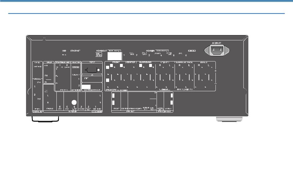
Rear Panel
For details, see (  p10)
p10)
9 |
Front Panel Rear Panel Remote |

Contents Connections Playback Setup
1.DIGITAL IN OPTICAL/COAXIAL jacks: Input TV or AV component digital audio signals with a digital optical cable or digital coaxial cable.
2.TUNER AM/FM terminal: Connect the supplied antennas.
3.COMPONENT VIDEO IN jacks: Input AV component video signals with a component video cable. (Compatible only with 480i or 576i resolution.)
4.Wireless antenna: Used for Wi-Fi connection or when using a BLUETOOTHenabled device. Adjust the angles according to the connection status.
5.USB port: Connect a USB storage device to play music files. (  p83) You can also supply power (5 V/1 A) to USB devices with a USB cable.
6.ETHERNET port: Connect to the network with a LAN cable.
7.VIDEO IN jacks: Input AV component video signals with an analog video cable.
8.RS-232C port: Connect a home control system equipped with an RS-232C port. For adopting a home control system, contact the specialized stores.
9.HDMI OUT jacks: Transmit video signals and audio signals with an HDMI cable connected to a monitor such as a TV or projector.
10.HDMI IN jacks: Transmit video signals and audio signals with an HDMI cable connected to an AV component.
11.AC INLET: Connect the supplied power cord.
12.GND terminal: Connect the ground wire of the turntable.
13.12V TRIGGER OUT jack: Connect a device equipped with a 12V trigger input jack to enable power link operation between the device and this unit.
(  p72)
p72)
14.AUDIO IN jacks: Input TV or AV component audio signals with an analog audio cable.
15.IR IN port: Connect a remote control receiver unit.(  p71)
p71)
16.SPEAKERS terminals: Connect speakers with speaker cables. (North American models support banana plugs.)
17.PRE OUT jacks: Connect a power amplifier. (  p57)
p57)
18.SUBWOOFER PRE OUT jacks: Connect a powered subwoofer with a subwoofer cable. Up to two powered subwoofers can be connected. The same signal is output from each SUBWOOFER PRE OUT jack.
19.ZONE 3 PRE/LINE OUT jacks: Output audio signals with an analog audio cable connected to a pre-main amplifier or a power amplifier in a separate room (ZONE 3).
HEIGHT 2 PRE OUT jacks: Connect a power amplifier. (  p57)
p57)
20.ZONE 2 PRE/LINE OUT jacks: Output audio signals with an analog audio cable connected to a pre-main amplifier or a power amplifier in a separate room (ZONE 2).
10 |
Front Panel Rear Panel Remote |
Contents Connections Playback Setup
Remote Controller
|
|
1. |
|
ON/STANDBY button |
|
|
|
|
|
1 |
|
2. |
Input selector buttons: Switches the input to be played. |
|
|
||||
|
|
3. |
Q (QUICK MENU) button: Pressing this button during playback can make |
||||||
|
|
|
settings such as "Tone" and "Level" quickly on the TV screen while playing. |
||||||
|
|
|
( |
p147) |
|
|
|
|
|
2 |
|
4. |
Cursor buttons and ENTER button: Select an item with the cursors, and press |
||||||
|
|
ENTER to confirm your selection. Pressing |
/ can switch the screen when a |
||||||
|
|
|
|||||||
|
|
|
music folder list or file list is not displayed on one screen on the TV. |
||||||
|
|
5. |
|
button: Display advanced setting items on the TV or the display to have a |
|||||
|
|
|
more enjoyable experience with this unit. ( |
p124) |
|
|
|||
3 |
bl |
6. VOLUME buttons |
|
|
|
|
|
||
|
|
7. |
|
button: Temporarily mutes audio. Press the button again to cancel muting. |
|||||
|
|
8. |
LISTENING MODE button: Select a listening mode ( p104). |
p98). |
|||||
4 |
|
|
MAIN/ZONE 2/ZONE 3 button: Control the multi-zone function ( |
||||||
|
9. |
Play buttons: Used for playback operations for the Music Server ( |
p86) or |
||||||
|
|
|
USB device ( p83). |
|
|
|
|
||
5 |
bm |
10. |
button: Used for repeat/random playback operations for the Music |
||||||
|
Server ( p86) or USB device ( |
p83). Each time you press the button, |
|||||||
|
|
|
the mode switches in the order of |
(1-track repeat), |
(folder repeat), and |
||||
|
|
|
|
(random). |
|
|
|
|
|
|
|
|
CLEAR button: Deletes all characters you have entered when entering text on |
||||||
6 |
|
11. |
the TV screen. |
|
|
|
|
|
|
7 |
|
|
button: Switches the information on the display and is used to operate RDS |
||||||
|
|
( |
p97). |
|
|
|
|
|
|
|
|
12. |
button: Returns the display to the previous state while setting. |
|
|||||
8 |
|
13. MODE button: Used to switch between automatic tuning and manual tuning for |
|||||||
|
|
AM/FM stations ( |
p93), or operate the multi-zone function ( p98). |
||||||
9 |
|
14. MEMORY button: Used to register AM/FM radio stations. ( |
p95) |
|
|||||
bk |
bn |
Tips |
If the remote controller does not work: The |
||||||
remote controller may have switched to the ZONE |
|||||||||
|
bo |
|
|
|
control mode. While pressing and holding MODE, |
||||
|
|
|
|
press the MAIN button for 3 seconds or more until |
|||||
|
|
|
|
|
|||||
|
|
|
|
|
the remote indicator blinks once, and then switch it |
||||
|
|
|
|
|
to the main room control mode. |
|
|
||
|
|
11 |
|
Front Panel Rear Panel Remote |
|
||||
Contents Connections Playback Setup
Connections
Connecting speakers |
13 |
Connecting the TV |
59 |
Connecting Playback Devices |
62 |
Connecting an AV Component in a Separate Room |
|
(Multi-zone Connection) |
66 |
Connecting Antennas |
69 |
Network Connection |
70 |
Connecting External Control Devices |
71 |
Connecting the Power Cord |
73 |
12 |
Front Panel Rear Panel Remote |
|
Contents Connections Playback Setup
Connecting speakers
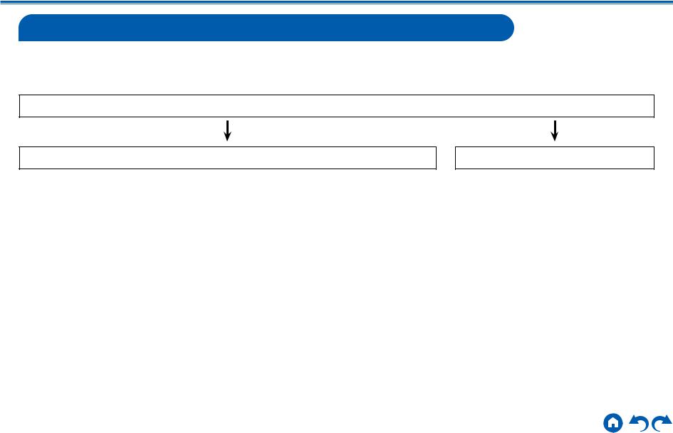
You can select the layout of speakers to be installed from various patterns when using this unit. Use the following flow chart to select the speaker layout that suits your speakers and usage environment. You can check the connection method and default settings. Dolby Atmos (  p106) listening mode faithfully reproduces the sound design recorded in the Dolby Atmos audio format by installing Surround Back Speakers or Height Speakers. Dolby Atmos enables the accurate placement of sound objects that have independent motion in a three-dimensional space with even greater clarity.
Do you enjoy sound with Dolby Atmos?
Yes
When using Surround Back
Speakers
•7.1 Channel System (  p45)
p45)
•7.1 Channel System + ZONE SPEAKER (  p46)
p46)
•7.1 Channel System (Bi-Amping the Speakers) (  p47)
p47)
When using 1 set of Height Speakers
•5.1.2 Channel System (  p48)
p48)
•5.1.2 Channel System + ZONE SPEAKER (  p49)
p49)
•5.1.2 Channel System (Bi-Amping the Speakers) (  p50)
p50)
•7.1.2 Channel System (  p51)
p51)
•7.1.2 Channel System + ZONE SPEAKER (  p52)
p52)
When using 2 sets of Height Speakers
•5.1.4 Channel System (  p53)
p53)
•5.1.4 Channel System + ZONE SPEAKER (  p54)
p54)
•7.1.4 Channel System (  p55)
p55)
•7.1.4 Channel System + ZONE SPEAKER (  p56)
p56)
No
•5.1 Channel System (  p42)
p42)
•5.1 Channel System + ZONE SPEAKER (  p43)
p43)
•5.1 Channel System (Bi-Amping the Speakers) (  p44)
p44)
13 |
Front Panel Rear Panel Remote |
Contents Connections Playback Setup
Speaker Installation
5.1 Channel System
2 3
3  1
1
6 *1
*1
*2
5 4
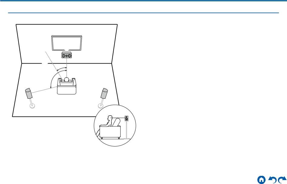
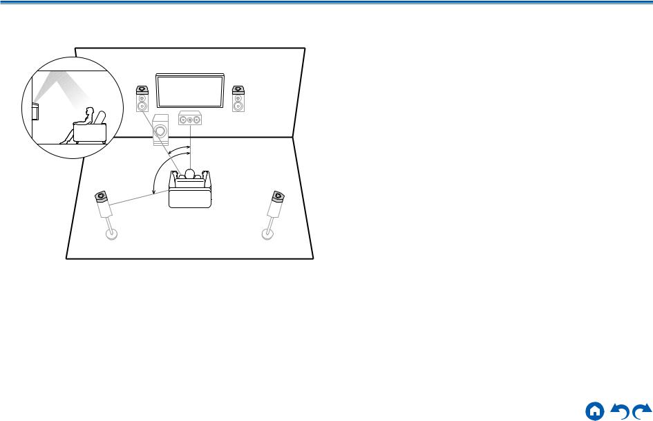
This is a basic 5.1 Channel System. Front speakers output the front stereo sound, and a center speaker outputs the sound of the center of the screen, such as dialogs and vocals. Surround speakers create the back sound field. Powered subwoofer reproduces the bass sound, and creates the rich sound field.
The front speakers should be positioned at ear height while the surround speakers should be positioned just above ear height. The center speaker should be set up facing the listening position at an angle. Placing the powered subwoofer between the center speaker and the front speaker gives you a natural sound even when playing music sources.
1,2 Front Speakers
3 Center Speaker
4,5 Surround Speakers
6 Powered Subwoofer
*1: 22° to 30°, *2: 120°
14 |
Front Panel Rear Panel Remote |
Contents Connections Playback Setup
7.1 Channel System
2 3
3  1
1
6 *1
*1
|
*2 |
5 |
4 |
|
*3 |
 8
8
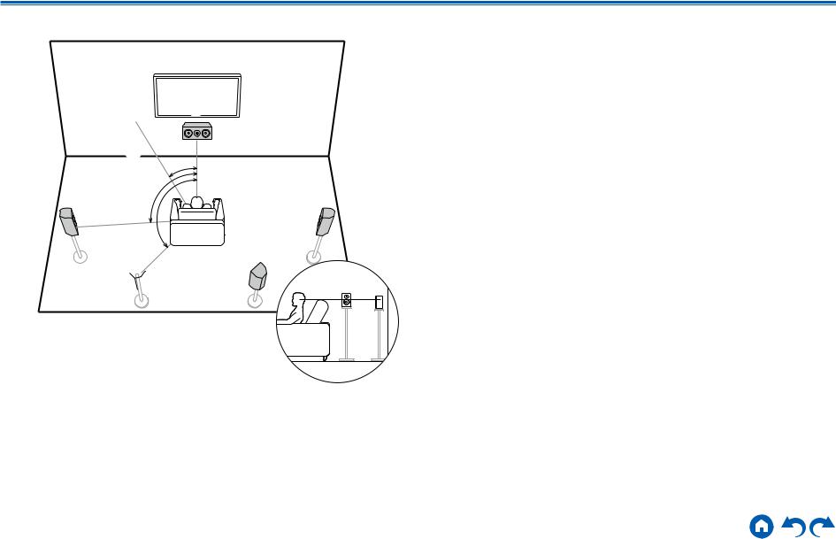
*1: 22° to 30°, *2: 90° to 110°, *3: 135° to 150°
7 |
This is a 7.1 Channel System that consists of the basic 5.1 Channel System
(  p14) and added surround back speakers. Front speakers output the
front stereo sound, and a center speaker outputs the sound of the center of the screen, such as dialogs and vocals. Surround speakers create the back sound field. Powered subwoofer reproduces the bass sound, and creates the rich sound field. Surround back speakers improves the sense of envelopment and connectivity of sound in the back sound field, and provides a more real sound field. Furthermore, by installing surround back speakers, when the input format is
Dolby Atmos, you can select the Dolby Atmos listening mode which realizes the most up-to-date 3D sound,
The front speakers should be positioned at ear height while the surround speakers should be positioned just above ear height. The center speaker should be set up facing the listening position at an angle. Placing the powered subwoofer between the center speaker and the front speaker gives you a natural
sound even when playing music sources. The surround back speakers should be positioned at ear height.
•If surround back speakers are installed, be sure to install surround speakers as well.
1,2 Front Speakers
3 Center Speaker
4,5 Surround Speakers
6 Powered Subwoofer
7,8 Surround Back Speakers
15 |
Front Panel Rear Panel Remote |

Contents Connections Playback Setup
5.1.2 Channel System
A 5.1.2 Channel System is a speaker layout consisting of the basic 5.1 Channel System (  p14) and added height speakers. Select the height speakers that suit your speakers and usage environment from the following three types.
Front High Speakers/Rear High Speakers
Installation Example (  p17)
p17)
Ceiling Speakers Installation Example
(  p18)
p18)
Dolby Enabled Speakers (Dolby Speakers)
Installation Example (  p19)
p19)
16 |
Front Panel Rear Panel Remote |
Contents Connections Playback Setup
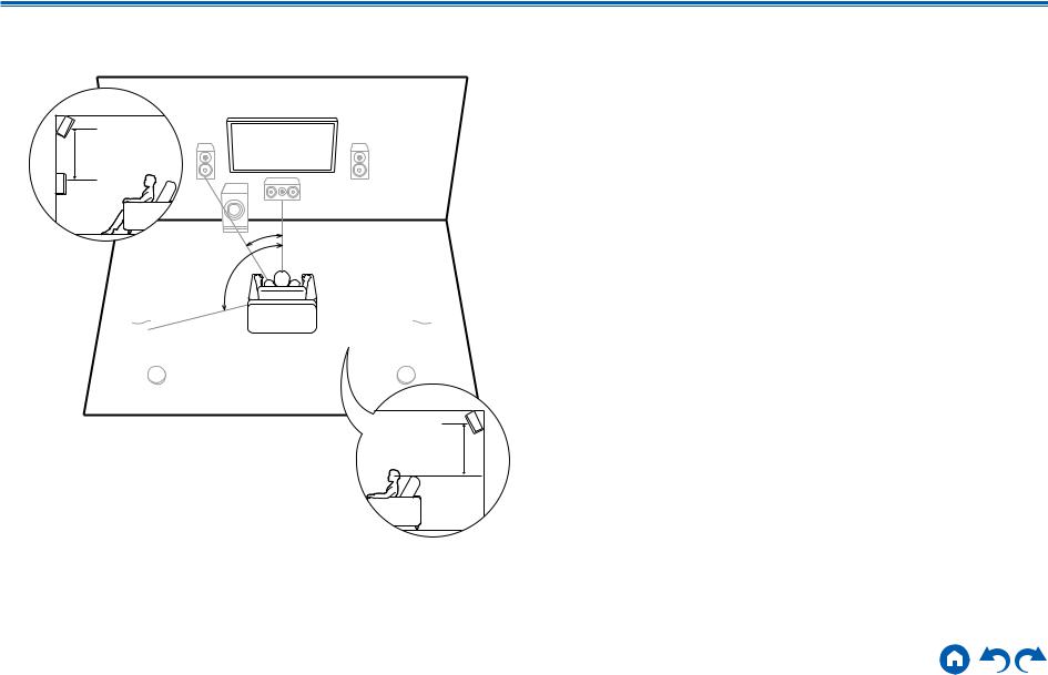
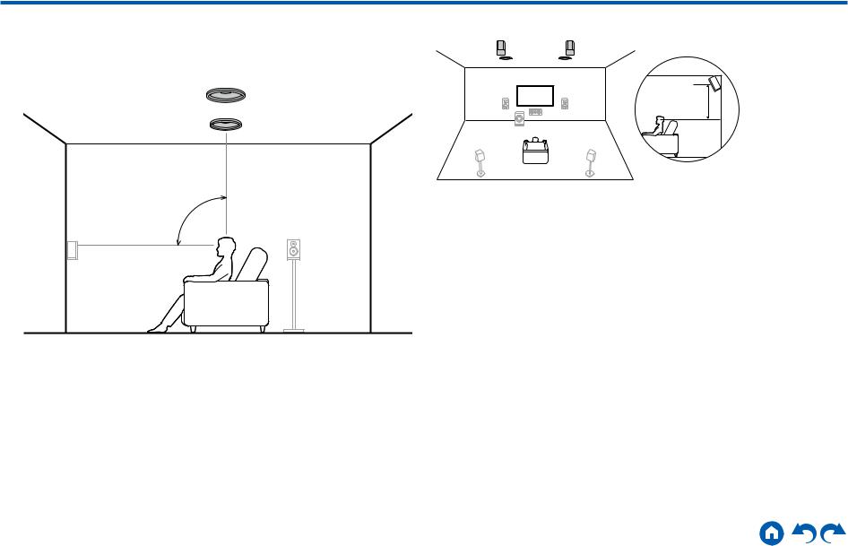
Front High Speakers/Rear High Speakers
Installation Example
8
 7
7
3´ (0.9 m) or more
*1
*2
This is a system with the basic 5.1 channel system (  p14) consisting of front speakers, a center speaker, surround speakers and a powered subwoofer, and added front high speakers or rear high speakers combined. By installing such height speakers, when the input format is Dolby Atmos, you can select the Dolby Atmos listening mode which realizes the most up-to-date 3D sound including overhead sound. Front high speakers or rear high speakers should be installed at least 3´/0.9 m higher than the front speakers.
Front high speakers should be installed directly above the front speakers, and the distance between the rear high speakers should match the distance between the front speakers. In both cases, the speakers should be set up facing the listening position at an angle.
7,8 Height Speakers
Choose one of the following:
•Front High Speakers
•Rear High Speakers
 8
8
*1: 22° to 30°, *2: 120°
 7
7
3´ (0.9 m) |
or more |
17 |
Front Panel Rear Panel Remote |
Contents Connections Playback Setup
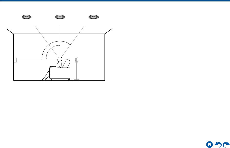
Ceiling Speakers Installation Example
8 8 8
7 7
7 7
7
*3
*2
*1
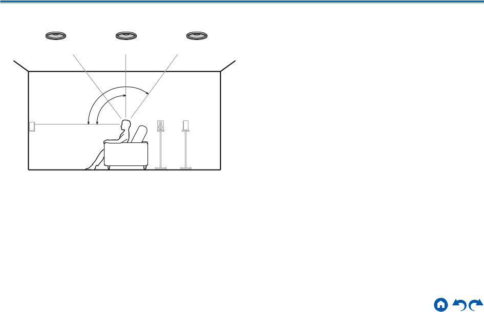
*1: 30° to 55°, *2: 65° to 100°, *3: 125° to 150°
This is a system with the basic 5.1 channel system (  p14) consisting of front speakers, a center speaker, surround speakers and a powered subwoofer, and added top front speakers or top middle speakers or top rear speakers combined. By installing such height speakers, when the input format is Dolby Atmos, you can select the Dolby Atmos listening mode which realizes the most up-to-date 3D sound including overhead sound. Install the top front speakers on the ceiling anterior to the seating position, top middle speakers on the ceiling directly above the seating position, and top rear speakers on the ceiling posterior to the seating position. The distance between each pair should match the distance between the front speakers.
•Dolby Laboratories recommends the setups of these types of height speakers to obtain the best Dolby Atmos effect.
7,8 Height Speakers
Choose one of the following:
•Top Front Speakers
•Top Middle Speakers
•Top Rear Speakers
18 |
Front Panel Rear Panel Remote |
Contents Connections Playback Setup
Dolby Enabled Speakers (Dolby Speakers)
Installation Example
8 |
7 |
|
*1 |
|
*2 |
8 |
7 |
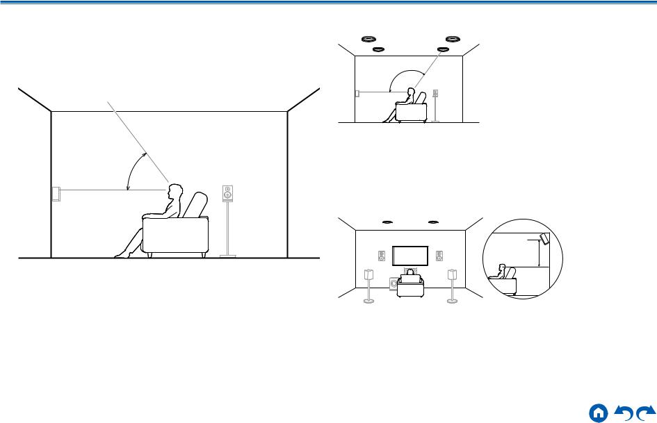
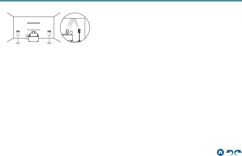
*1: 22° to 30°, *2: 120°
This is a system with the basic 5.1 channel system (  p14) consisting of front speakers, a center speaker, surround speakers and a powered subwoofer, and added Dolby enabled speakers (front) or Dolby enabled speakers (surround) combined. Dolby enabled speakers are special speakers designed to face the ceiling, so that the sound is heard from overhead by bouncing the sound off the ceiling. By installing such height speakers, when the input format is Dolby Atmos, you can select the Dolby Atmos listening mode which realizes the most up-to- date 3D sound including overhead sound.
Install them either on the front speakers or on the surround speakers.
7,8 Height Speakers
Choose one of the following:
•Dolby Enabled Speakers (Front)
•Dolby Enabled Speakers (Surround)
19 |
Front Panel Rear Panel Remote |

Contents Connections Playback Setup
7.1.2 Channel System
A 7.1.2 Channel System is a speaker layout consisting of the 7.1 Channel System (  p15) and added height speakers. Select the height speakers that suit your speakers and usage environment from the following three types.
Front High Speakers/Rear High Speakers
Installation Example (  p21)
p21)
Ceiling Speakers Installation Example
(  p22)
p22)
Dolby Enabled Speakers (Dolby Speakers)
Installation Example (  p23)
p23)
20 |
Front Panel Rear Panel Remote |
Contents Connections Playback Setup
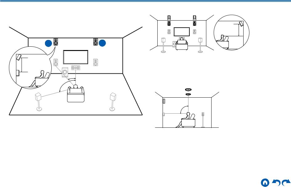
Front High Speakers/Rear High Speakers
Installation Example
bk
 9
9
3´ (0.9 m) or more
*1
*2
bk *3 |
9 |
*1: 22° to 30°, *2: 90° to 110°, *3: 135° to 150°
3´ (0.9 m) or more
This is a system with the 7.1 channel system (  p15) consisting of front speakers, a center speaker, surround speakers, surround back speakers and a powered subwoofer, and added front high speakers or rear high speakers combined. By installing such height speakers, when the input format is Dolby Atmos, you can select the Dolby Atmos listening mode which realizes the most
up-to-date 3D sound including overhead sound. Front high speakers or rear high speakers should be installed at least 3´/0.9 m higher than the front speakers. Front high speakers should be installed directly above the front speakers, and the distance between the rear high speakers should match the distance between the front speakers. In both cases, the speakers should be set up facing the listening position at an angle.
9,10 Height Speakers Choose one of the following:
•Front High Speakers
•Rear High Speakers
21 |
Front Panel Rear Panel Remote |
Contents Connections Playback Setup
Ceiling Speakers Installation Example
bk bk bk 9 9
9 9
9
*3
*2
*1
*1: 30° to 55°, *2: 65° to 100°, *3: 125° to 150°
This is a system with the 7.1 channel system (  p15) consisting of front speakers, a center speaker, surround speakers, surround back speakers and a powered subwoofer, and added top front speakers or top middle speakers or top rear speakers combined. By installing such height speakers, when the input format is Dolby Atmos, you can select the Dolby Atmos listening mode which
realizes the most up-to-date 3D sound including overhead sound. Install the top front speakers on the ceiling anterior to the seating position, top middle speakers on the ceiling directly above the seating position, and top rear speakers on the ceiling posterior to the seating position. The distance between each pair should match the distance between the front speakers.
•Dolby Laboratories recommends the setups of these types of height speakers to obtain the best Dolby Atmos effect.
9,10 Height Speakers Choose one of the following:
•Top Front Speakers
•Top Middle Speakers
•Top Rear Speakers
22 |
Front Panel Rear Panel Remote |

Contents Connections Playback Setup
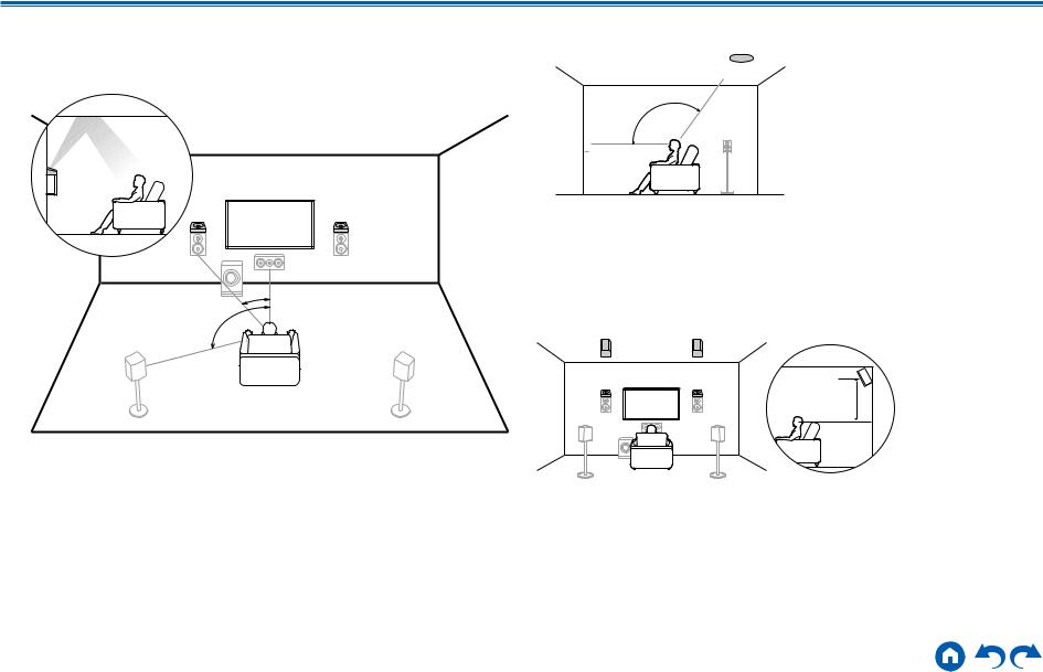
Dolby Enabled Speakers (Dolby Speakers)
Installation Example
|
bk |
9 |
|
*1 |
|
bk |
*2 |
9 |
|
||
|
*3 |
|
|
bk |
9 |
*1: 22° to 30°, *2: 90° to 110°, *3: 135° to 150° |
|
|
This is a system with the 7.1 channel system (  p15) consisting of front speakers, a center speaker, surround speakers, surround back speakers and a powered subwoofer, and added Dolby enabled speakers (front), Dolby enabled speakers (surround) or Dolby enabled speakers (surround back) combined. Dolby enabled speakers are special speakers designed to face the ceiling, so that the sound is heard from overhead by bouncing the sound off the ceiling. By installing such height speakers, when the input format is Dolby Atmos, you can select the Dolby Atmos listening mode which realizes the most up-todate 3D sound including overhead sound.
Install them either on the front speakers, on the surround speakers or on the surround back speakers.
9,10 Height Speakers Choose one of the following:
•Dolby Enabled Speakers (Front)
•Dolby Enabled Speakers (Surround)
•Dolby Enabled Speakers (Surround Back)
23 |
Front Panel Rear Panel Remote |

Contents Connections Playback Setup
5.1.4 Channel System
A 5.1.4 Channel System is a speaker layout combining 2 sets of the height speakers, 1 set of left and right at the front and 1 set of left and right at the rear, to the basic 5.1 Channel System (  p14). By installing the height speakers, when the input format is Dolby Atmos, you can select the Dolby Atmos listening mode which realizes the most up-to-date 3D sound including overhead sound. Combination of 2 height speakers can be selected from following.
Combination example when Top Front
Speakers are used at the front (  p25)
p25)
Combination example when Top Middle
Speakers are used at the front (  p27)
p27)
Combination example when Front High
Speakers are used at the front (  p28)
p28)
Combination example when Dolby Enabled
Speakers (Front) are used at the front (  p30)
p30)
24 |
Front Panel Rear Panel Remote |
Contents Connections Playback Setup
Combination example when Top Front
Speakers are used at the front
About the top front speakers
 8
8
 7
7
*1
*1: 30° to 55°
The top front speakers are installed on the ceiling at front of the listening position, and the width between the left and right speakers is optimal to match the one for the front speakers. When the top front speakers are used in front, the combination of the height speakers at the rear can be selected from the following 3 examples shown at the right.
7,8 Top Front Speakers
(Example 1) Use top rear speakers at the rear
8 |
bk |
7 |
9 |
*2 |
|
*2: 125° to 150°
The top rear speakers are installed on the ceiling at rear of the listening position, and the width between the left and right speakers is optimal to match the one for the front speakers.
9,10 Top Rear Speakers
(Example 2) Use rear high speakers at the rear
bk 8 7
8 7  9
9
3´ (0.9 m) |
or more |
The width between the rear high speakers should match the one for the front speakers, and they should be installed minimum of 3’/0.9 m higher than the front speakers, and tilted so they will point toward the listener.
9,10 Rear High Speakers
25 |
Front Panel Rear Panel Remote |
Contents Connections Playback Setup
(Example 3) Use Dolby Enabled Speakers (Surround) at the rear
8
 7
7
bk 

 9
9
The Dolby enabled speakers are the special speaker that the sound is emitted toward the ceiling, and have the effect the sound to come from above by reflecting the sound on the ceiling.
The Dolby enabled speakers (surround) are installed on top of the surround speakers.
9,10 Dolby Enabled Speakers (Surround)
26 |
Front Panel Rear Panel Remote |
Contents Connections Playback Setup
Combination example when Top Middle |
Use rear high speakers at the rear |
||
Speakers are used at the front |
bk |
8 7 |
9 |
About the top middle speakers |
|
|
|
|
|
|
|
|
8 |
3´ (0.9 m) |
|
|
|
|
7 |
or more |
|
|
|
|
The width between the rear high speakers should match the one for the front |
|
*1 |
speakers, and they should be installed minimum of 3’/0.9 m higher than the front |
|
|
speakers, and tilted so they will point toward the listener. |
|
|
9,10 |
Rear High Speakers |
*1: 65° to 100°
The top middle speakers are installed on the ceiling immediately above the listening position, and the width between the left and right speakers is optimal to match the one for the front speakers. When the top middle speakers are used in front, the rear high speakers in the figure at the right can be used at the rear.
7,8 Top Middle Speakers
27 |
Front Panel Rear Panel Remote |
Contents Connections Playback Setup
Combination example when Front High
Speakers are used at the front
About the front high speakers
8 |
7 |
3´ (0.9 m) or more
*1
*2
*1: 22° to 30°, *2: 120°
Install the front high speakers immediately above the front speakers minimum of 3’/0.9 m higher, and tilted so they will point toward the listener. When the front high speakers are used in front, the combination of the height speakers at the rear can be selected from the following 4 examples shown at the right.
7,8 Front High Speakers
(Example 1) Use rear high speakers at the rear
|
|
3´ (0.9 m) |
|
|
|
|
|
or more |
The width between the rear high speakers should match the one for the front speakers, and they should be installed minimum of 3’/0.9 m higher than the front speakers, and tilted so they will point toward the listener.
9,10 Rear High Speakers
(Example 2) Use top middle speakers at the rear
|
|
|
|
|
*3 |
|
|
*3: 65° to 100° |
|
The top middle speakers are installed on the ceiling immediately above the listening position, and the width between the left and right speakers is optimal to match the one for the front speakers.
9,10 Top Middle Speakers
28 |
Front Panel Rear Panel Remote |

Contents Connections Playback Setup
(Example 3) Use top rear speakers at the rear
|
|
|
|
|
*4 |
*4: 125° to 150° |
|
The top rear speakers are installed on the ceiling at rear of the listening position, and the width between the left and right speakers is optimal to match the one for the front speakers.
9,10 Top Rear Speakers
(Example 4) Use Dolby Enabled Speakers (Surround) at the rear


The Dolby enabled speakers are the special speaker that the sound is emitted toward the ceiling, and have the effect the sound to come from above by reflecting the sound on the ceiling.
The Dolby enabled speakers (surround) are installed on top of the surround speakers.
9,10 Dolby Enabled Speakers (Surround)
29 |
Front Panel Rear Panel Remote |
|
Contents Connections Playback Setup
Combination example when Dolby Enabled
Speakers (Front) are used at the front
About the Dolby enabled speakers (front)
8 |
7 |
|
*1 |
*2 |
|
*1: 22° to 30°, *2: 120°
The Dolby enabled speakers are the special speaker that the sound is emitted toward the ceiling, and have the effect the sound to come from above by reflecting the sound on the ceiling.
The Dolby enabled speakers (front) are installed on top of the front speakers. When the Dolby enabled speakers (front) are used in front, the combination of the height speakers at the rear can be selected from the following 3 examples shown at the right.
7,8 Dolby Enabled Speakers (Front)
(Example 1) Use top rear speakers at the rear
bk 9
9
*3
78
*3: 125° to 150°
The top rear speakers are installed on the ceiling at rear of the listening position, and the width between the left and right speakers is optimal to match the one for the front speakers.
9,10 Top Rear Speakers
(Example 2) Use rear high speakers at the rear
bk 9
8 |
7 |
3´ (0.9 m) |
|
|
|
|
|
or more |
The width between the rear high speakers should match the one for the front speakers, and they should be installed minimum of 3’/0.9 m higher than the front speakers, and tilted so they will point toward the listener.
9,10 Rear High Speakers
30 |
Front Panel Rear Panel Remote |
 Loading...