


AV Receiver
TX-DS989
Instruction Manual
|
|
|
|
|
|
|
|
|
|
|
|
|
MASTER VOLUME |
STANDBY/ON |
|
|
|
|
|
|
|
|
|
|
|
|
|
STANDBY |
|
|
|
|
|
|
|
|
|
|
|
|
|
|
ZONE 2 (GRN ) |
|
|
|
|
|
|
|
|
|
|
|
|
DISPLAY |
REC ( RED ) |
VIDEO 1 |
VIDEO 2 |
VIDEO 3 |
VIDEO 4 |
VIDEO 5 |
TAPE 1 |
TAPE 2 |
AM |
FM |
PHONO |
C D |
OPEN/CLOSE |
DVD |
POWER
ON OFF
AV RECEIVER TX-DS989
Thank you for purchasing the Onkyo AV Receiver. Please read this manual thoroughly before making connections and plugging in the unit. Following the instructions in this manual will enable you to obtain optimum performance and listening enjoyment from your new AV Receiver. Please retain this manual for future reference.
Contents |
|
Before using |
|
Important Safeguards ....................................... |
2 |
Precautions ........................................................ |
3 |
Contents ............................................................ |
4 |
Supplied accessories ......................................... |
5 |
Features ............................................................. |
6 |
Before using remote controller ......................... |
7 |
Facilities and connections |
|
Front panel facilities ......................................... |
8 |
Remote controller ........................................... |
11 |
Rear panel facilities ........................................ |
12 |
Example of how to connect your equipment ..... |
16 |
Connecting speakers ....................................... |
20 |
Connecting antennas ....................................... |
22 |
Connecting to the IR IN ZONE 2 input ......... |
24 |
Connecting to the IR IN MAIN input ............ |
25 |
Connecting a graphic equalizer |
|
and power amplifiers ................................... |
26 |
Connecting the power ..................................... |
27 |
Setting OSD menu |
|
The On-Screen Display (OSD) menu ............ |
28 |
Speaker Setup ................................................. |
30 |
Input Setup ...................................................... |
34 |
Listening Mode Setup .................................... |
42 |
Preference ....................................................... |
46 |
Zone2 OSD Setup ........................................... |
48 |
About .............................................................. |
48 |
Enjoying music or videos |
|
Enjoying music or videos in the remote zone ... |
49 |
Listening to Radio Broadcasts ........................ |
50 |
Enjoying music or videos |
|
with the TX-DS989 ...................................... |
52 |
Recording a source ......................................... |
54 |
Remote controller |
|
Using remote controller .................................. |
56 |
Programming the commands of |
|
remote controllers for other devices |
|
into the remote controller ............................. |
61 |
Using a Macro function .................................. |
64 |
Appendix |
|
Troubleshooting guide .................................... |
68 |
The default settings ........................................ |
71 |
Your system setting ........................................ |
72 |
Specifications ................................................. |
76 |
WARNING:
TO REDUCE THE RISK OF FIRE OR ELECTRIC SHOCK, DO NOT EXPOSE THIS APPLIANCE TO RAIN OR MOISTURE.
CAUTION:
TO REDUCE THE RISK OF ELECTRIC SHOCK, DO NOT REMOVE COVER (OR BACK). NO USER-SERVICEABLE PARTS INSIDE. REFER SERVICING TO QUALIFIED SERVICE PERSONNEL.
WARNING |
|
AVIS |
RISK OF ELECTRIC SHOCK |
|
RISQUE DE CHOC ELECTRIQUE |
DO NOT OPEN |
|
NE PAS OUVRIR |
|
|
|
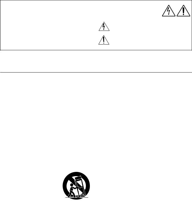
The lightning flash with arrowhead symbol, within an equilateral triangle, is intended to alert the user to the presence of uninsulated “dangerous voltage” within the product’s enclosure that may be of sufficient magnitude to constitute a risk of electric shock to persons.
The exclamation point within an equilateral triangle is intended to alert the user to the presence of important operating and maintenance (servicing) instructions in the literature accompanying the appliance.
Important Safeguards
1. Read Instructions – All the safety and operating instructions should be read before the appliance is operated.
2. Retain Instructions – The safety and operating instructions should be retained for future reference.
3. Heed Warnings – All warnings on the appliance and in the operating instructions should be adhered to.
4. Follow Instructions – All operating and use instructions should be followed.
5. Cleaning – Unplug the appliance from the wall outlet before cleaning. The appliance should be cleaned only as recommended by the manufacturer.
6. Attachments– Do not use attachments not recommended by the appliance manufacturer as they may cause hazards.
7. Water and Moisture –Do not use the appliance near water –for example, near a bath tub, wash bowl, kitchen sink, or laundry tub; in a wet basement; or near a swimming pool; and the like.
8. Accessories – Do not place the appliance on an unstable cart, stand, tripod, bracket, or table. The appliance may fall, causing serious injury to a child or adult, and serious damage to the appliance. Use only with a cart, stand, tripod, bracket, or table recommended by the manufacturer, or sold with the appliance. Any mounting of the appliance
should follow the manufacturer’s instructions, and should use a mounting accessory recom-
mended by the manufacturer. 9. An appliance and cart combina-
tion should be moved with care. Quick stops, excessive force, and
uneven surfaces may cause the appliance and cart combination S3125A
to overturn.
10.Ventilation – Slots and openings
in the cabinet are provided for ventilation and to ensure reliable operation of the appliance and to protect it from overheating, and these openings must not be blocked or covered. The openings should never be blocked by placing the appliance on a bed, sofa, rug, or other similar surface. The appliance should not be placed in a built-in installation such as a bookcase or rack unless proper ventilation is provided. There should be free space of at least 20 cm (8 in.) and an opening behind the appliance.
11.Power Sources – The appliance should be operated only from the type of power source indicated on the marking label. If you are not sure of the type of power supply to your home, consult your appliance dealer or local power company.
12.Grounding or Polarization – The appliance may be equipped with a polarized alternating current line plug (a plug having one blade wider than the other). This plug will fit into the power outlet only one way. This is a safety feature. If you are unable to insert the plug fully into the outlet, try reversing the plug. If the plug should still fail to fit, contact your electrician to replace your obsolete outlet. Do not defeat the safety purpose of the polarized plug.
2
13.Power-Cord Protection – Power-supply cords should be routed so that they are not likely to be walked on or pinched by items placed upon or against them, paying particular attention to cords at plugs, convenience receptacles, and the point where they exit from the appliance.
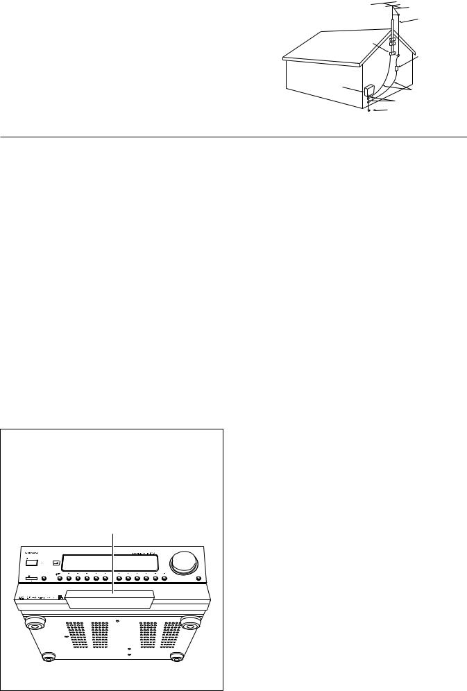
14.Outdoor Antenna Grounding – If an outside antenna or cable system is connected to the appliance, be sure the antenna or cable system is grounded so as to provide some protection against voltage surges and built-up static charges. Article 810 of the National Electrical Code, ANSI/NFPA 70, provides information with regard to proper grounding of the mast and supporting structure, grounding of the lead-in wire to an an- tenna-discharge unit, size of grounding conductors, location of antenna-discharge unit, connection to grounding electrodes, and requirements for the grounding electrode. See Figure 1.
15.Lightning – For added protection for the appliance during a lightning storm, or when it is left unattended and unused for long periods of time, unplug it from the wall outlet and disconnect the antenna or cable system. This will prevent damage to the appliance due to lightning and power-line surges.
16.Power Lines – An outside antenna system should not be located in the vicinity of overhead power lines or other electric light or power circuits, or where it can fall into such power lines or circuits. When installing an outside antenna system, extreme care should be taken to keep from touching such power lines or circuits as contact with them might be fatal.
17.Overloading – Do not overload wall outlets, extension cords, or integral convenience receptacles as this can result in a risk of fire or electric shock.
18.Object and Liquid Entry – Never push objects of any kind into the appliance through openings as they may touch dangerous voltage points or short-out parts that could result in a fire or electric shock. Never spill liquid of any kind on the appliance.
19.Servicing – Do not attempt to service the appliance yourself as opening or removing covers may expose you to dangerous voltage or other hazards. Refer all servicing to qualified service personnel.
20.Damage Requiring Service – Unplug the appliance form the wall outlet and refer servicing to qualified service personnel
under the following conditions:
A.When the power-supply cord or plug is damaged,
B.If liquid has been spilled, or objects have fallen into the appliance,
C.If the appliance has been exposed to rain or water,
D.If the appliance does not operate normally by following the operating instructions. Adjust only those controls that are covered by the operating instructions as an improper adjustment of other controls may result in damage and will often require extensive work by a qualified technician to restore the appliance to its normal operation,
E.If the appliance has been dropped or damaged in any way, and
F.When the appliance exhibits a distinct change in performance – this indicates a need for service.
21.Replacement Parts–When replacement parts are required, be sure the service technician has used replacement parts specified by the manufacturer or have the same characteristics as the original part. Unauthorized substitutions may result in fire, electric shock, or other hazards.
22.Safety Check – Upon completion of any service or repairs to the appliance, ask the service technician to perform safety checks to determine that the appliance is in proper operation condition.
23.Wall or Ceiling Mounting – The appliance should be mounted to a wall or ceiling only as recommended by the manufacturer.
24.Heat – The appliance should be situated away from heat sources such as radiators, heat registers, stoves, or other appliances (including amplifiers) that produce heat.
Precautions
FIGURE 1:
EXAMPLE OF ANTENNA GROUNDING AS PER NATIONAL ELECTRICAL CODE, ANSI/NFPA 70
|
ANTENNA |
|
|
LEAD IN |
|
|
WIRE |
|
|
GROUND |
|
|
CLAMP |
|
|
ANTENNA |
|
|
DISCHARGE UNIT |
|
|
(NEC SECTION 810-20) |
|
ELECTRIC |
|
|
SERVICE |
|
|
EQUIPMENT |
GROUNDING CONDUCTORS |
|
|
||
|
(NEC SECTION 810-21) |
|
|
GROUND CLAMPS |
|
NEC – NATIONAL ELECTRICAL CODE |
POWER SERVICE GROUNDING |
|
ELECTRODE SYSTEM |
||
|
||
S2898A |
(NEC ART 250, PART H) |
|
|
1. Warranty Claim
You can find the serial number on the rear panel of this unit. In case of warranty claim, please report this number.
2. Recording Copyright
Recording of copyrighted material for other than personal use is illegal without permission of the copyright holder.
3. AC Fuse
The fuse is located inside the chassis and is not user-serviceable. If power does not come on, contact your Onkyo authorized service station.
For U.S. model
Note to CATV system installer:
This reminder is provided to call the CATV system installer’s attention to Article 820-40 of the NEC, ANSI/NFPA 70, which provides guidelines for proper grounding and, in particular, specifies that the cable ground shall be connected to the grounding system of the building, as close to the point of cable entry as practical.
FCC Information for User
CAUTION:
4. Care
From time to time you should wipe the front and rear panels and the cabinet with a soft cloth. For heavier dirt, dampen a soft cloth in a weak solution of mild detergent and water, wring it out dry, and wipe off the dirt. Following this, dry immediately with a clean cloth. Do not use rough material, thinners, alcohol or other chemical solvents or cloths since these could damage the finish or remove the panel lettering.
5. Power
WARNING
BEFORE PLUGGING IN THE UNIT FOR THE FIRST TIME, READ THE FOLLOWING SECTION CAREFULLY.
The voltage of the available power supply differs according to country or region. Be sure that the power supply voltage of the area where this unit will be used meets the required voltage (e.g., AC 230 V, 50 Hz or AC 120 V, 60 Hz) written on the rear panel.
Precautions during unpacking
•The unit is extremely heavy, so be careful when lifting it so as not to cause an injury. Do not lift or move the unit by holding it at the door on the front panel. Doing so may damage the front door.
•When packaged, the door on the front panel is taped to the unit. Before use, be sure to remove this tape.
Taped
MASTER VOLUME
STANDBY/ON
POWER
AV RECEIVER TX-DS989
• The taping for packaging may be different for your product.
The user changes or modifications not expressly approved by the party responsible for compliance could void the user’s authority to operate the equipment.
NOTE:
This equipment has been tested and found to comply with the limits for a Class B digital device, pursuant to Part 15 of the FCC Rules. These limits are designed to provide reasonable protection against harmful interference in a residential installation. This equipment generates, uses and can radiate radio frequency energy and, if not installed and used in accordance with the instructions, may cause harmful interference to radio communications. However, there is no guarantee that interference will not occur in a particular installation. If this equipment does cause harmful interference to radio or television reception, which can be determined by turning the equipment off and on, the user is encouraged to try to correct the interference by one or more of the following measures:
•Reorient or relocate the receiving antenna.
•Increase the separation between the equipment and receiver.
•Connect the equipment into an outlet on a circuit different from that to which the receiver is connected.
•Consult the dealer or an experienced radio/TV technician for help.
For Canadian model
CAUTION: THIS DIGITAL APPARATUS DOES NOT EXCEED THE CLASS B LIMITS FOR RADIO NOISE EMISSION FROM DIGITAL APPARATUS SET OUT IN THE RADIO INTERFERENCE REGULATIONS OF THE CANADIAN DEPARTMENT OF COMMUNICATIONS.
For models having a power cord with a polarized plug: CAUTION: TO PREVENT ELECTRIC SHOCK, MATCH WIDE BLADE OF PLUG TO WIDE SLOT, FULLY INSERT.
Modele pour les Canadien
ATTENTION:L'INTERFÉ RENCE RADIO É LECTRIQUE GÉ NÉ RÉ E PAR CET APPAREIL NUMÉ RIQUE DE TYPE B NE DÉ PASSE PAS LES LIMITES É NONCÉ ES DANS LE RÈ GLEMENT SUR LES PERTURBATIONS RADIO É LECTRIQUES, SECTION APPAREIL NUMÉ RIQUE, DU MINISTÈ RE DES COMMUNICATIONS.
Sur les modèles dont la fiche est polarisée: ATTENTION:POUR É VITER LES CHOCS É LECTRIQUES, INTRODUIRE LA LAME LA PLUS LARGE DE LA FICHE DANS LA BORNE CORRESPONDANTE DE LA PRISE ET POUSSER JUSQU’AU FOND.
3
Contents
Before using |
|
Important Safeguards ......................................... |
2 |
Precautions ......................................................... |
3 |
Contents .............................................................. |
4 |
Supplied accessories ......................................... |
5 |
Features ............................................................... |
6 |
Before using remote controller ......................... |
7 |
Installing the remote controller batteries ......................... |
7 |
Using the remote controller .............................................. |
7 |
Facilities and connections |
|
Front panel facilities ........................................... |
8 |
Front panel ........................................................................ |
9 |
Lower buttons in the front door ....................................... |
9 |
Front panel display ......................................................... |
10 |
Remote controller ............................................. |
11 |
Rear panel facilities .......................................... |
12 |
Example of how to connect your equipment .... |
16 |
Standard connections ...................................................... |
17 |
Connecting your audio components .............................. |
18 |
Connecting your video components .............................. |
18 |
Connecting speakers ....................................... |
20 |
Ideal speaker configuration ............................................ |
20 |
Minimum speaker configuration for |
|
surround sound playback ........................................ |
20 |
Speaker placement .......................................................... |
20 |
Connecting speakers ....................................................... |
21 |
Connecting the speaker cable ......................................... |
21 |
Connecting a subwoofer ................................................. |
21 |
Connecting antennas ....................................... |
22 |
Connecting the included antennas ................................. |
22 |
Assembling the AM loop antenna .................................. |
22 |
Connecting the AM antenna cable ................................. |
22 |
Connecting an FM outdoor antenna ............................... |
23 |
Connecting an AM outdoor antenna .............................. |
23 |
Directional linkage ......................................................... |
23 |
Connecting the antenna cable to |
|
the 75/300 Ω antenna adapter (not included) ......... |
23 |
Connecting to the IR IN ZONE 2 input ............ |
24 |
Outline ............................................................................ |
24 |
Connecting the main and remote zones ......................... |
24 |
Connecting to the IR IN MAIN input ................ |
25 |
Outline ............................................................................ |
25 |
Connecting a graphic equalizer and power |
|
amplifiers ...................................................... |
26 |
Connecting a graphic equalizer ...................................... |
26 |
Connecting power amplifiers ......................................... |
26 |
Connecting the power ...................................... |
27 |
Connecting the power ..................................................... |
27 |
Setting OSD menu |
|
|
The On-Screen Display (OSD) menu .............. |
28 |
|
Navigating through the OSD menu ................................ |
29 |
|
Speaker Setup ................................................... |
30 |
|
1. |
Speaker Setup menu ............................................... |
30 |
1-1. Speaker Config sub-menu ...................................... |
30 |
|
1-2. Speaker Distance sub-menu ................................... |
31 |
|
1-3. Level Calibration sub-menu ................................... |
32 |
|
1-4. Bass Peak Level sub-menu .................................... |
33 |
|
1-5. LFE Level Setup sub-menu .................................... |
33 |
|
Input Setup ........................................................ |
34 |
|
2. |
Input Setup menu ................................................... |
34 |
2-1. Digital Setup sub-menu .......................................... |
34 |
|
2-2. Multichannel Setup sub-menu ............................... |
36 |
|
2-3. Video Setup sub-menu ........................................... |
36 |
|
2-4. Listening Mode Preset sub-menu .......................... |
37 |
|
|
Input source signals ................................................ |
38 |
|
Listening Modes ..................................................... |
38 |
2-5. Delay sub-menu ...................................................... |
40 |
|
2-6. Sound Effect sub-menu .......................................... |
40 |
|
2-7. Character Input sub-menu ...................................... |
41 |
|
2-8. Miscellaneous Setup .............................................. |
41 |
|
Listening Mode Setup ...................................... |
42 |
|
3. Listening Mode Setup menu .................................. |
42 |
|
|
Description listening mode parameters ................. |
44 |
Preference ......................................................... |
46 |
|
4. |
Preference menu ..................................................... |
46 |
4-1. Volume Setup sub-menu ........................................ |
46 |
|
4-2. OSD Setup sub-menu ............................................. |
47 |
|
4-3. OSD Tweak ............................................................ |
47 |
|
Zone2 OSD Setup ............................................. |
48 |
|
5. Zone2 OSD Setup menu ........................................ |
48 |
|
About |
.................................................................. |
48 |
6. |
About menu ............................................................ |
48 |
6-1. Lock Setup sub-menu ............................................. |
48 |
|
6-2. ....................................................................Version |
48 |
|
Enjoying music or videos |
|
|
Enjoying ..music or videos in the remote zone |
49 |
|
Controlling .........the TX-DS989 from the remote zone |
49 |
|
Controlling ..the TX-DS989 without the remote controller |
49 |
|
Listening ........................to Radio Broadcasts |
50 |
|
Listening .............................to FM/AM Radio Stations |
50 |
|
Tuning .............................................into a radio station |
50 |
|
Presetting ................................................a radio station |
51 |
|
Selecting ......................................a preset radio station |
51 |
|
Erasing .........................................a preset radio station |
51 |
|
Enjoying ...music or videos with the TX-DS989 |
52 |
|
Selecting ...............................................an input source |
52 |
|
Adjusting .....................................................the volume |
52 |
|
Changing ..........................................the listening mode |
52 |
|
Listening .............................................with headphones |
52 |
|
Using ...................the many features of the TX-DS989 |
52 |
|
If one ................of the messages shown below appears |
53 |
|
Enjoying ..................................the multichannel output |
53 |
|
4
Contents
Recording a source .......................................... |
54 |
To record the input source signal you are currently |
|
watching or listening to .......................................... |
54 |
To record an input source signal different from that |
|
you are currently watching or listening to ............. |
55 |
Recording the video from one source and |
|
the audio from another ............................................ |
55 |
Remote controller |
|
Using remote controller ................................... |
56 |
Overview ......................................................................... |
56 |
Using the remote controller to control each device ....... |
56 |
Controlling the TX-DS989 ............................................. |
56 |
Controlling an Onkyo CD player ................................... |
58 |
Controlling an Onkyo MD recorder ............................... |
58 |
Controlling an Onkyo cassette tape deck ....................... |
59 |
Calling up a preset radio station .................................... |
59 |
Controlling an Onkyo DVD player ................................ |
60 |
SAT, CABLE, VCR, and TV MODE buttons ................ |
60 |
Programming the commands of |
|
remote controllers for other devices |
|
into the remote controller ........................... |
61 |
Programming procedure ................................................. |
61 |
Erasing the programmed command from one button .... |
63 |
Erasing all the commands programmed under |
|
a MODE button ....................................................... |
63 |
Using a Macro function .................................... |
64 |
What is a Macro function? ............................................. |
64 |
Programming a Macro function ..................................... |
64 |
Running a Macro function ............................................. |
64 |
Programming the Direct Macro function ....................... |
65 |
Running a Direct Macro function .................................. |
65 |
Erasing a macro from the MODE MACRO button ....... |
66 |
Erasing a direct macro from the |
|
DIRECT MACRO button ....................................... |
66 |
Erasing all commands and macros that have been |
|
programmed ............................................................ |
67 |
Appendix |
|
Troubleshooting guide ..................................... |
68 |
POWER .......................................................................... |
68 |
SPEAKERS .................................................................... |
68 |
FM/AM TUNER ............................................................. |
69 |
VIDEO and AUDIO ....................................................... |
69 |
REMOTE CONTROLLER ............................................ |
69 |
OTHER ........................................................................... |
70 |
The default settings .......................................... |
71 |
Your system setting .......................................... |
72 |
Inputs .............................................................................. |
72 |
Speakers .......................................................................... |
74 |
OSD Setup ...................................................................... |
74 |
ZONE2 ............................................................................ |
74 |
About .............................................................................. |
74 |
Remote controller ........................................................... |
75 |
(Macro mode programming memo ............................... |
67) |
Specifications ................................................... |
76 |
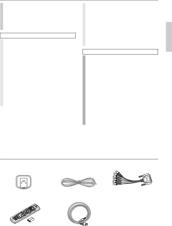
Supplied accessories
Check that the following accessories are supplied with the TX-DS989.
|
|
|
|
|
|
|
|
|
|
|
|
|
|
|
|
|
|
|
|
|
|
|
|
|
|
|
|
|
|
|
|
|
|
|
|
|
|
|
|
|
|
|
|
|
AM loop antenna × 1 |
T-shaped FM antenna × 1 |
DB-25↔ RCA6ch cable × 1 |
||||||
RC390M
Remote controller × 1 |
Power cord × 1 |
Batteries (AA, R6, or UM-3) × |
2 |
5

Features
■ AMPLIFIER FEATURES
130 WATTS MINIMUM OF CONTINUOUS RMS POWER to each of the 7channels into 8 Ω , from 20 Hz to 20 kHz with no more than 0.05%THD (FTC rating)–clean high-current amplification provides incredible dynamic range for seamless reproduction of even the most demanding cinema soundtracks, as well as animatedly rich music at any volume level.
7.1-CHANNEL AMPLIFIER–the first receiver to achieve this feat in one chassis–the TX-DS989 provides unparalleled power and clarity to all 7.1-channels for a room-filling sound experience seconds to none.
LUCASFILM THX® ULTRA CERTIFIED–in addition to the amazing ability to drive 7.1 channels, the TX-DS989 also boasts the distinction of carrying the exclusive THX Ultra badge of approval–assurance that this receiver passed (and often exceeds) THX's numerous requirements in such areas as frequency response, distortion, power output, and stability.
192kHz/24-BIT D/A CONVERTERS FOR ALL CHANNELS– the first receiver in the industry to utilize these powerful converters for all seven channels–the TX-DS989's DACs not only boast a dynamic range of 120dB, they also process more information faster and are virtually resistant to clock jitter, to ensure the best performance possible from DVD-Audio and other upcoming formats, while also producing cleaner, clearer sound form DVDs and CDs.
WIDE RANGE AMPLIFIER TECHNOLOGY(WRAT)
WRAT virtually eliminates the adverse effects of counterelectromotive force by: 1) applying an uncommonly low amount of NFB (negative feed-back), 2) using carefully selected, high-tolerance, wide range parts in all critical sections, and 3) incorporating innovative circuit topology based upon decades of high-end amplifier-design experience–the final result is a flat response beyond 100kHz, making the TX-DS989 ideal for such high-resolution formats as DVD-Audio and Super Audio CD, and other upcoming digital formats.
■ FLEXBILITY FEATURES
FUTURE-PROOF INTERFACE ARCHITECTURE–a versatile RS232 port allows the TX-DS989's powerful 4Mbit Flash Memory to be directly computer accessed for installing such future upgrades as new DSP algorithms, new surround formats/parameters, and other types of processing updates.
ZONE 2 MULTIROOM/MULTISOURCE CAPABILITY–a full set of line outs for audio, composite video, and S-video, allows for set-up of an additional system in another room–connect an optional infrared eye in Zone 2, and complete second-room control can be achieved with such A/V distribution control systems as Xantech® , Niles® , to name but a few.
*Manufactured under license from Dolby Laboratories.
“Dolby”, “Pro Logic” and the double-D symbol  are trademarks of Dolby Laboratories. Confidential Unpublished Works. ©1992-1997
Dolby Laboratories, Inc. All rights reserved.
•Theater-Dimensional and the symbol 


 are trademarks of ONKYO CORPORATION.
•Lucasfilm, THX, THX Ultra and THX Surround EX are registered trademarks of Lucasfilm LTD.
•Re-Equalization and the “Re-EQ” logo are trademarks of Lucasfilm Ltd. Manufactured under license of Lucasfilm Ltd.
•Manufactured under license from Digital Theater Systems, Inc. US Pat. No.5,451,942 and other worldwide patents issues and pending. “DTS” and “DTS Digital Surround” are trademarks of Digital Theater Systems, Inc.© 1996 Digital Theater Systems, Inc. All rights reserved.
•Xantech is a registered trademark of Xantech Corporation.
•Niles is a registered trademark of Niles Audio Corporation.
■ AUDIO/VIDEO FEATURES
THX SURROUND EX® BUILT IN to decode the additional two back surround channels from THX Surround EX-encoded DVDs and laserdiscs, for incredibly real 360˚ surround sound effects and precise sound location.
DTS® DECODER BUILT IN to decode the impeccable 5.1-channel digital audio from DTS-encoded DVD-Video discs, DVD-Audio discs, CDs and laserdiscs.
DOLBY®* DIGITAL DECODER BUILT IN to decode the 5.1- channel crystal-clear digital audio of DVDs, Digital TV, HDTV, satellite broadcasts and other sources.
DOLBY® PRO LOGIC™ DECODER
MPEG DECODEING for full compatibility with MPEG-encoded software and broadcasts.
DIGITAL UPSAMPLING MODE–the first receiver to have 192kHz/24-bit DACs for all channels enables the TX-DS989 to take a 48kHz digital signal and double its sampling frequency to 96kHz– twice as much signal information, for greater detail and clarity.
THEATER-DIMENSIONAL™ VIRTUAL SURROUND MODE
A/V SYNC DELAY
LUCASFILM THX® ULTRA FULL-ENHANCEMENT PACKAGE–includes such sophisticated DSP enhancements as Cinema Re-EQ™ , Timbre Matching™ , Adaptive Decorrelation™ , and Bass Management™ to ensure accurate reproduction of the movietheater experience in the home.
7.1-CHANNEL EXTERNAL INPUTS
COMPONENT VIDEO OUTPUTS
■ OTHER FEATURES
40 FM/AM RANDOM PRESETS INTELLIVOLUME
ABSOLUTE/RELATIVE SWITCHABLE VOLUME DISPLAY
THX Ultra
Before any home theatre component can be THX Ultra certified, it must pass a rigorous series of quality and performance tests. Only then can a product feature the THX Ultra logo, which is your guarantee that the Home Theatre products you purchase will give you superb performance for many years to come. THX Ultra requirements define hundreds of parameters, including power amplifier performance, and pre-amplifier performance and operation for both digital and analog domains. THX Ultra receivers also features proprietary THX technologies (e.g. THX Mode, see page 38) which accurately translate film soundtracks for home theater playback.
6
Before using remote controller
1 |
2 |
3 |
TX-DS989 |
Remote control sensor |
STANDBY indicator |
30˚ |
30˚ |
Approx. 5 meters |
Memory preservation
This unit does not require memory preservation batteries. A built-in memory power backup system preserves the contents of the memory during power failures and even when the POWER switch is set to off. The POWER switch must be set to on in order to charge the backup system.
The memory preservation period after the unit has been turned off varies depending on climate and placement of the unit. On the average, memory contents are protected over a period of a few weeks after the last time the unit has been turned off. This period is shorter when the unit is exposed to a highly humid climate.
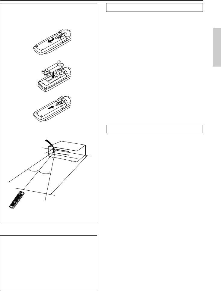
Installing the remote controller batteries
1.Remove the battery compartment cover by pressing the tab and sliding the cover.
2.Insert two AA (R6 or UM-3) batteries into the battery compartment. Carefully follow the polarity diagram (positive (+) and negative (–) symbols) inside the battery compartment.
3.After batteries are installed and seated correctly, replace the compartment cover.
Notes:
•Do not mix new batteries with old batteries or different kinds of batteries.
•To avoid corrosion, remove the batteries if the remote controller is not to be used for a long time.
•Remove dead batteries immediately to avoid damage from corrosion. If the remote controller does not operate smoothly, replace both the batteries at the same time.
•The life of the batteries supplied is about six months but this will vary depending on usage.
Using the remote controller
Point the remote controller toward the remote control sensor. The STANDBY indicator lights up when the unit receives a signal from the remote controller.
Notes:
•Place the unit away from strong light such as direct sunlight or inverted fluorescent light which can prevent proper operation of the remote controller.
•Using another remote controller of the same type in the same room or using the unit near equipment which uses infrared rays may cause operational interference.
•Do not put objects on the remote controller. The buttons of the remote controller may be pressed by mistake and drain the batteries.
•Make sure the audio rack doors do not have colored glass. Placing the unit behind such doors may prevent proper remote controller operation.
•If there is any obstacle between the remote controller and the remote control sensor, the remote controller will not operate.
7
Front panel facilities
Here is an explanation of the controls and displays on the front panel of the TX-DS989.
Front panel
1 2 |
3 |
Display |
4 |
5 |
|
|
|
|
MASTER VOLUME |
|
STANDBY/ON |
|
|
|
|
STANDBY |
|
|
|
|
|
ZONE 2 (GRN ) |
|
|
REC ( RED )
|
DISPLAY |
DVD |
VIDEO 1 |
VIDEO 2 |
VIDEO 3 |
VIDEO 4 |
VIDEO 5 |
TAPE 1 |
TAPE 2 |
AM |
FM |
PHONO |
C D |
OPEN/CLOSE |
POWER |
|
|
|
|
|
|
|
|
|
|
|
|
|
|
ON |
OFF |
|
|
|
|
|
|
|
|
|
|
|
|
|
|
|
|
|
|
|
|
|
|
|
|
|
|
|
AV RECEIVER TX-DS989 |
|
6 |
|
|
|
|
|
7 |
|
|
Front door |
|
|
||
Lower buttons in the front door
CLEAR |
PHONES |
AV RECEIVER TX-DS989
9C E
8 0 A B D F G H
Front panel display
1 |
2 |
3 4 |
|||||||||
|
|
|
|
|
|
|
|
|
|
|
|
DOLBY DIGITAL |
|
|
|
SLEEP |
|
|
|
|
|||
MPEG |
DTS |
|
|
|
INPUT |
DIGITAL |
ANALOG |
||||
DOLBY PRO LOGIC |
|
|
|
|
|
|
|
|
|
||
|
|
|
|
|
|
|
|
|
|
VIDEO |
|
|
|
|
|
|
|
1 2 3 4 5 |
|
COMPONENT |
|||
|
|
|
|
|
|
DVD |
1 2 3 |
||||
5
8
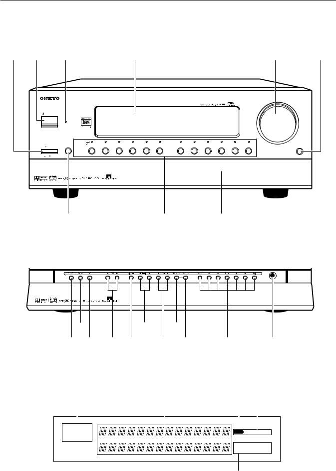
Front panel facilities
Front panel
POWER
After plugging in the power cord into the rear panel and wall outlet, pressing this button connects the TX-DS989 to the AC mains and turns it on.
•Before turning on the power, make sure all cables are properly connected.
•Turning on the TX-DS989 may cause a momentary power surge that might interfere with other electrical equipment on the same circuit. If this is a problem, plug the TX-DS989 into a different electrical circuit.
STANDBY/ON
Pressing this button while the main power is turned on the STANDBY indicator lights up and the front display turns off. Pressing it again returns it to the standby state. This state turns off the display, disables control functions, and turns off all outputs to the main zone (those for the remote zone remain available).
STANDBY indicator
Digital format:
The current input source is set for a digital format of “Auto.”
Bass level:
The current bass level is +2.
Treble level:
The current treble level is -2.
Input Source Buttons (DVD, VIDEO 1–5, TAPE 1–2, AM, FM, PHONO, and CD)
These buttons are used to select the input source for the main zone. When an input source is selected, the indicator will light in orange. To select the input source for the remote zone (Zone 2) or recording out (Rec Out), first press the Zone 2 or Rec Out button, and then the desired input source button.
Lower buttons in the front door
MASTER VOLUME |
Caution: |
The MASTER VOLUME knob is used to control the volume for the main zone. The volume for the remote zone (Zone 2) is independent.
OPEN/CLOSE
Press this button to open and close the front door that covers the lower buttons.
DISPLAY
The DISPLAY button is used to display information about the current input source signal. Each time you press the display button, the screen changes to show you different information concerning the input signal. The screen changes as follows:
Program format → Sampling frequency → Digital input → Digital format → Bass level → Treble level.
If the input source signal does not have any information for a particular screen, then that screen will be skipped.
•Displaying the data of the current input source
Each display is explained below.
LFE(Low Frequency Effect)
Program format:
Front channel Surround channel
Source signal |
48 kHz |
Sampling frequency:
Sampling frequency
Digital input:
The current input source is set for digital input at OPT1.
The front door of the receiver is motorized. Use the open/close button to open or close the door. Manually opening or closing the door, or moving the receiver while holding the door, will cause the door to malfunction or break.
Rec Out
Press the Rec Out button to output to a recording component for recording purposes. After pressing the Rec Out button, press one of the input source selector buttons within 8 seconds to select the component to record to. When one is selected, the indicator above that button will light in red. To record from the same input source that you are using (that is selected for the main zone), press the Rec Out button twice in succession.
Note:
The Rec Out and Zone 2 buttons use the same circuit and therefore cannot be used at the same time.
When Rec Out is selected, nothing is output from Zone 2.
Zone 2
The TX-DS989 includes a second signal path separate from the main one that can be used for a remote zone (Zone 2) or for making recordings. By connecting an additional amplifier or other video equipment to the Zone 2 outputs, you can output to a separate room an input source that is different from that being used in the main room. This allows you to watch one program in one room while somebody else is watching a different program in another.
Press the Zone 2 button to enable output to the ZONE 2 outputs. After pressing the Zone 2 button, press one of the input source selector buttons within 8 seconds to select the input source for the remote zone. When one is selected, the indicator above that button will light in green. To use the same input source for the both the main and remote zones, press the Zone 2 button twice in succession.
Note: |
|
The Rec Out and Zone 2 buttons use the same circuit and therefore |
|
cannot be used at the same time. |
|
When Zone 2 is selected, the currently selected input source is |
9 |
output from the recording terminal. |
Front panel facilities
Off
When not using either Rec Out or Zone 2, press that button and then press the Off button to turn off the signal. If the Rec Out or Zone 2 signal is turned on and the connected component is not turned on, the electric signal will still be sent through the circuitry and the excess load may cause deterioration of the audio signal.
 DSP
DSP 
Press these buttons to scroll through the listening modes and set a new one for the input source you are currently listening to. For each different input signal, different listening modes are possible. See page 38 for a detailed explanation of the different listening modes.
Dimmer
Press to set the brightness of the front display. There are 4 settings available: normal, dark, very dark, and off.
•The dimmer control for the front display can be performed at the remote controller.
 Tuning
Use these buttons to change the tuner frequency. The tuner frequency is displayed in the front display and it can be changed in 50 kHz increments for FM and 10 kHz increments for AM. When a station is tuned into, “> <” or “
 ” will appear in the front display.
When FM is selected, you can hold down one of the tuning buttons and then release it to activate the auto-search feature. It will search for a station in the direction of the button you pressed and stop when it tunes into one.
 Preset
When AM or FM is selected as the input source, press one of these buttons to jump to a radio station that you preset using the MEMORY button. Pressing the right button moves from the most recently preset station to older ones, and pressing the left button moves in the reverse order.
FM Mode
If you are listening to an FM radio station in stereo and the sound cuts out or there is a great deal of noise, then press this button. The “MONO” display will appear and the output will change to mono. Though you will not hear the audio in stereo, this may stop the sound from cutting out and reduce excess noise.
Memory
This button only operates when FM or AM is selected as the input source. This button allows you to preset frequencies for stations when using the FM/AM tuner. You can preset up to 40 stations (or frequencies) to be used with the PRESET buttons.
Menu,  , , Enter,
  ,
,  , Exit
These buttons are used with the On Screen Display (OSD) menu. They also perform the same functions as the OSD MENU,  (upper edge of ENTER button),
  (lower edge of ENTER button),
 (left edge of ENTER button),
  (right edge of ENTER button), ENTER, and EXIT RETURN buttons on the remote
controller.
Menu: Press to bring up the OSD menu.
Exit: Press to exit the OSD menu when at the Menu Screen, or move to one screen previous to the one that is displayed if at any other screen.
 and
and  : When selecting items in the OSD Menu, press these buttons to move the on-screen cursor (or the highlighted portion) upward and downward.
 and
and  : When setting parameters in the OSD menu, press these buttons to select parameter values or modes.
Enter: Press to display the screen for the selected item in the OSD Menu.
PHONES
This is a standard stereo jack for connecting stereo headphones. The audio for the front right and left speakers are sent to the headphone speakers. When the headphones are plugged in, the listening mode automatically changes to stereo and output to the speakers is stopped.
Front panel display
Listening mode or digital input format indicators
Multi function display
Sleep indicator
Input source format indicator
Video display
10
Remote controller
1
2 3
4 

 E 5
E 5


 FE
FE
6


7


 G
G
8


 H I
H I
9 |
|
|
|
|
J |
0A |
AUDIO |
|
|
MUTING |
LK |
|
TRACK |
DISC |
|||
B |
|
|
|
|
|
|
REC |
|
OPEN/CLOSE |
|
|
|
DVD |
|
|
CD |
|
C |
T1 |
T2 |
TUN |
PH |
|
|
V1 |
V2 |
V3 |
V– |
|
|
STEREO |
DIRECT |
DSP |
|
|
|
|
1 |
2 |
3 |
|
D |
SURROUND |
THX |
DSP |
|
|
|
4 |
5 |
6 |
|
|
|
Re-EQ |
CH SEL |
LEVEL + |
|
|
|
|
7 |
8 |
9 |
|
|
LATE NIGHT DIMMER |
LEVEL – |
M |
||
|
+ 10 |
0 |
ENT |
||
HOME THEATER CONTROLLER
RC-390M
For a more detailed explanation of how to use the remote controller, refer to pages 56 through 67.
SEND/LEARN indicator
LCD display
POWER ON/STNBY button
Be aware that pressing the STNBY button only places the TX-DS989 in standby and does not turn the power completely off.
SLEEP button
DIRECT MACRO button
MODE buttons
DISPLAY/DVD SET button
CH  buttons
EXIT/RETURN button
AUDIO button
TRACK button
CD/TAPE/DVD/MD operation buttons
Input Selector buttons
Numeric key/STEREO/DIRECT/THX/
DSP ,
,  /SURROUND/Re-EQ/LATE NIGHT/ CH SEL/LEVEL+,–/DIMMER buttons
LIGHT button
MODE MACRO button
OSD/MENU button
ENTER/cursor buttons
VOL  button
TEST/TV/VCR button
MUTING button
DISC button
ENT button
11
Rear panel facilities
Here is an explanation of the terminals found on the rear of the TX-DS989 and how they are used. Before connecting your audio and video components, be sure to read this section carefully and then proceed to the explanations on how to connect each individual component (see pages 16).
Improper connection
Inserted completely
•Be sure to always refer to the instructions that came with the component that you are connecting.
•Do not plug in the power cord until all connections have been made.
•For input jacks, red connectors (marked R) are used for the right channel, white connectors (marked L) are used for the left channel, and yellow connectors (marked V) are used for video connection.
•Insert all plugs and connectors securely. Improper connections can result in noise, poor performance, or damage to the equipment.
•Do not bind audio/video connection cables with power cords and speaker cables. Doing so may adversely affect the picture and sound quality.
|
R |
L |
C |
PRE OUT |
|
VIDEO |
S VIDEO |
|
|
|
|
|
|
|
|
|
|
|
|
|
|
|
AC 120V 60Hz |
|
|
|
|
AMP |
|
|
|
|
|
AC-3 |
|
|
|
|
|
|
|
|
|
|
|
|
|
SWITCHED |
|
|
|
|
IN |
1 |
|
|
1 |
|
|
|
|
|
|
|
|
|
|
|
|
|
AC OUTLETS TOTAL 120W 1A MAX. |
|||
|
|
|
|
|
|
|
RF |
|
COMPONENT |
|
|
|
|
|
|
|
|
|
|
|
|
|||
|
|
|
|
SUB |
|
|
|
|
|
|
|
|
|
|
|
|
|
|
|
|
|
|||
|
FRONT |
|
|
|
MONITOR |
|
|
|
|
VIDEO |
|
|
|
|
|
|
|
|
|
|
|
|
||
AM |
|
|
WOOFER |
|
|
|
|
|
|
|
|
|
|
|
|
|
|
|
|
|||||
|
|
|
OUT |
|
|
|
|
|
|
|
|
|
|
|
|
|
|
|
|
|
||||
ANT. |
|
|
|
|
|
|
|
DIGITAL |
|
|
INPUT 1 |
|
|
INPUT 2 |
|
|
INPUT 3 |
|
|
OUTPUT |
|
|
|
|
|
|
|
|
|
|
|
|
|
Y |
PR |
|
|
|
|
|
|
|
|
||||||
|
|
|
|
2 |
|
|
2 |
|
OUTPUT |
|
PB |
Y |
PB |
PR |
Y |
PB |
PR |
Y |
PB |
PR |
|
|
||
|
|
|
|
|
|
|
|
|
(COAXIAL) |
|
|
|
|
|
|
|
|
|
|
|
|
|
|
|
|
SURR |
|
R |
L |
|
|
|
|
|
|
|
|
|
|
|
|
|
|
|
|
|
|
|
|
|
|
|
|
ZONE 2 |
|
OUT |
1 |
|
|
|
|
|
|
|
|
|
|
|
|
|
|
|
|
|
|
|
|
|
|
|
|
DIGITAL |
|
|
|
|
|
|
|
|
|
|
|
|
|
|
|
||
FM |
SURR |
|
|
|
|
|
|
|
|
SURROUND (SURR) |
|
|
|
|
|
|
|
|
|
|
|
|||
ANT. |
BACK |
|
|
|
|
|
|
|
INPUT |
|
|
AV RECEIVER |
|
|
|
|
|
|
|
|
||||
|
|
|
|
|
|
|
(COAXIAL) |
|
|
SPEAKERS |
|
|
|
|
|
|
|
|
|
|
||||
75 |
|
|
|
|
|
|
|
|
|
|
|
|
MODEL NO. TX-DS989 |
|
|
|
|
|
|
|
||||
|
|
|
|
|
|
OUT |
2 |
|
|
|
|
|
|
|
|
|
|
|
|
|||||
|
|
|
|
|
|
|
|
|
|
|
|
|
|
|
|
|
|
|
|
|
|
|
||
|
|
|
|
VIDEO |
|
|
|
BACK |
|
|
|
|
|
|
|
|
|
|
|
|
|
|
||
MULTI |
|
|
OUT |
|
1 |
|
|
|
|
L |
|
|
|
|
|
|
|
|
|
|
|
|
|
|
|
|
|
|
|
|
IN |
3 |
|
|
|
|
|
|
|
|
|
|
|
|
|
|
|
||
|
|
|
|
|
|
|
|
|
|
|
|
|
|
|
|
|
|
|
|
|
|
|||
CHANNEL |
|
|
|
|
|
|
|
|
|
|
|
|
|
|
|
|
|
|
|
|
|
L |
|
|
INPUT |
TAPE |
|
|
|
|
|
|
|
|
|
|
|
|
|
|
|
|
|
|
|
|
|
|
|
|
|
|
|
|
|
|
|
|
|
|
|
|
|
|
|
|
|
|
|
|
|
|
AC |
|
|
1 |
|
IN |
|
|
|
|
|
|
|
|
|
|
|
|
|
|
|
|
|
|
FRONT |
|
|
|
|
|
|
|
|
|
OUT |
4 |
|
|
|
|
|
|
|
|
|
|
|
|
|
|
INLET |
|
|
|
|
|
|
|
|
BACK |
|
|
|
|
|
|
|
|
|
|
|
SPEAKERS |
|
||||
|
|
|
|
|
|
|
|
|
|
|
|
|
|
|
|
|
|
|
|
|
|
|||
|
|
|
|
VIDEO |
|
|
|
|
|
|
|
|
|
|
|
|
|
|
|
|
|
|||
|
|
|
|
|
|
|
|
R |
|
|
|
|
|
|
|
|
|
|
|
|
|
|
||
|
|
|
OUT |
|
2 |
|
|
|
|
|
|
|
|
|
|
|
|
|
|
|
|
|
|
|
|
|
|
|
|
|
|
|
|
|
|
|
|
|
|
|
|
|
|
|
|
|
|
||
|
|
|
|
|
|
|
IN |
5 |
|
|
|
|
|
|
|
|
|
|
|
|
|
R |
|
|
|
TAPE |
|
|
|
|
|
|
|
|
|
|
|
|
|
|
|
|
|
|
|
|
|
|
|
|
2 |
|
IN |
VIDEO |
|
|
|
DIGITAL |
L |
|
|
|
|
|
|
|
|
|
|
|
|
CAUTION: |
||
|
|
|
|
|
IN |
|
|
|
|
|
|
|
|
|
|
|
|
|
||||||
|
|
|
|
|
3 |
|
|
OUTPUT |
|
|
|
|
|
|
|
|
|
|
|
|
|
SPEAKER IMPEDANCE |
||
|
|
|
|
|
|
|
|
(OPTICAL) |
|
|
|
|
|
|
|
|
|
|
|
|
|
|||
|
|
|
|
|
|
|
|
|
|
|
|
|
|
|
|
|
|
|
|
|
|
|
6 OHMS MIN. PER EACH |
|
|
CD |
|
IN |
VIDEO |
|
|
1 |
|
|
|
|
|
|
|
|
|
|
|
|
|
CENTER |
SPEAKER TERMINAL |
||
|
|
|
|
IN |
|
|
|
|
|
|
|
|
|
|
|
|
|
|
SPEAKER |
|
|
|||
RS 232 |
|
|
|
4 |
|
|
|
|
|
|
|
|
|
|
|
|
|
|
|
|
|
|||
|
|
|
|
|
|
|
DIGITAL |
|
|
|
|
|
|
|
|
|
|
|
|
|
|
|
||
|
|
|
|
|
|
|
|
|
|
|
|
|
|
|
|
|
|
|
|
|
|
|
IR IN |
|
|
PHONO |
|
IN |
VIDEO |
|
|
2 |
INPUT |
|
|
|
|
|
|
|
|
|
|
|
|
|
|
||
|
|
|
|
|
(OPTICAL) |
R |
|
|
|
|
|
|
|
|
|
|
|
|
MAIN |
ZONE 2 |
||||
|
|
|
|
|
IN |
|
|
|
|
|
|
|
|
|
|
|
|
|
||||||
|
|
|
|
|
5 |
|
|
|
|
|
|
|
|
|
|
|
|
|
|
|
||||
|
|
|
|
|
|
|
|
|
|
|
|
|
|
|
|
|
|
|
|
|
|
|
|
|
R |
L |
|
DVD |
|
3 |
|
|
|
|
CAUTION:SPEAKER IMPEDANCE |
|
|
|
|
IN |
|
|
|
|
|
|
|
6 OHMS MIN. PER EACH |
GND |
R |
L |
VIDEO |
S VIDEO |
SPEAKER TERMINAL |
|
12
Rear panel facilities
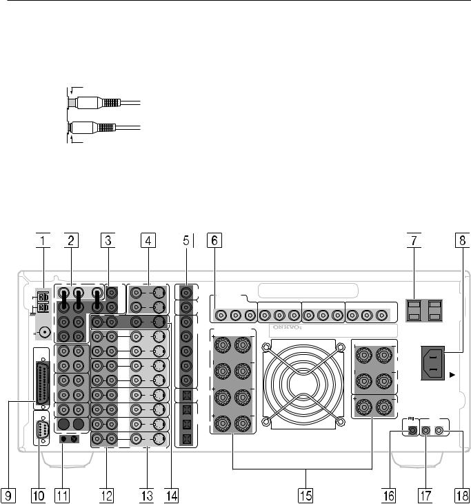
ANTENNA
These jacks are for connecting the FM indoor antenna and AM loop antenna that are supplied with the TX-DS989.
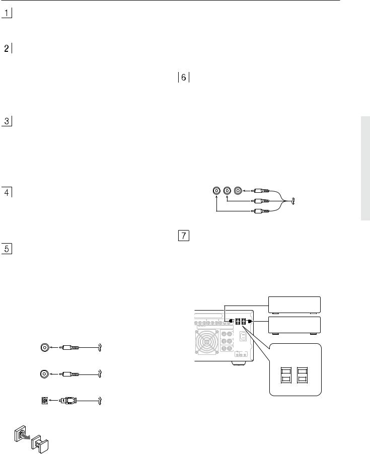
AMP IN
These jacks are for connecting a graphic equalizer for further control of the audio output.
•When connecting a graphic equalizer, remove the attached jumper plugs and store them carefully so as not to lose them.
•Only remove the jumper plugs when required. After you finish using an AMP IN jack, replace the jumper plug.
PRE OUT
These jacks are for connecting auxiliary power amplifiers.
•When connecting auxiliary power amplifiers, remove the attached jumper plugs and store them carefully so as not to lose them.
•Only remove the jumper plugs when required. After you finish using a PRE OUT jack, replace the jumper plug.
MONITOR OUT
There are 2 monitor outputs and each one includes both composite video and S-video configurations. When connecting two video monitors or televisions, be aware that the OSD interface can only be used with MONITOR OUT 1 (OSD will not be displayed on the video monitor connected to MONITOR OUT 2).
DIGITAL INPUT/OUTPUT
(coaxial, optical, and input-only AC-3RF)
These are the digital audio inputs and outputs. There are 5 digital inputs with coaxial jacks, 3 with optical jacks, and 1 AC-3RF input. The inputs accept digital audio signals from a compact disc, LD, DVD, or other digital source component. For digital output, there is 1 coaxial output and 1 optical output. The digital outputs can be connected to MD recorders, CD recorders, DAT decks, or other similar components.
COAXIAL Coaxial cable
AC-3RF Coaxial cable
OPTICAL Optical fiber cable
Optical digital input terminal
An optical digital input terminal is equipped with a protection cap. When connecting, remove this cap. When not using, put the cap back on the terminal.
•When using the digital inputs and outputs, make sure to also connect the analog connections whenever possible.
•When using one of the optical input or output jacks, remove the protective cap and keep it safely. When the jack is not used, replace the protective cap.
•When using an optical input or output jack, always use an optical fiber cable.
COMPONENT VIDEO INPUT/OUTPUT
If your DVD player or other device has component video connectors, be sure to connect them to these component video connectors on the TX-DS989. The TX-DS989 has three component video input connectors to obtain the color information (Y, PB, PR) directly from the recorded DVD signal or other video component and one component video output connector to output it directly into the matrix decoder of the display device. By sending the pure DVD component video signal directly, the DVD signal forgoes the extra processing that normally would degrade the image. The result is vastly increased image quality, with incredibly lifelike colors and crisp detail.
Y PB PR RCA type
AC OUTLETS
The TX-DS989 is supplied with two AC mains outlets for connecting the power cords from other devices so that their power is supplied through the TX-DS989. By doing this, you can use the STANDBY/ON button on the TX-DS989 to turn on and off the connected devices as well.
|
|
|
|
|
|
|
|
AC 120V 60Hz |
|
|
|
|
|
|
|
|
SWITCHED |
|
|
|
|
|
|
|
|
AC OUTLETS TOTAL 120W 1A MAX. |
|
INPUT 2 |
|
|
INPUT 3 |
|
|
OUTPUT |
|
Y |
P |
P |
Y |
P |
P |
Y |
P |
P |
AV RECEIVER
MODEL NO. TX-DS989
L
AC
FRONT INLET
SPEAKERS
R
CAUTION:
SPEAKER IMPEDANCE
6 OHMS MIN. PER EACH CENTER SPEAKER TERMINAL
SPEAKER
IR IN
MAIN ZONE 2
AC 120V 60Hz
SWITCHED
AC OUTLETS TOTAL 120W 1A MAX.
U.S. and Canadian
models
Caution
Make sure that the total capacity of the other components connected to this unit does not exceed the capacity that is printed on the rear panel. For the North American model, the capacity is 120 watts.
13
Rear panel facilities
AC INLET
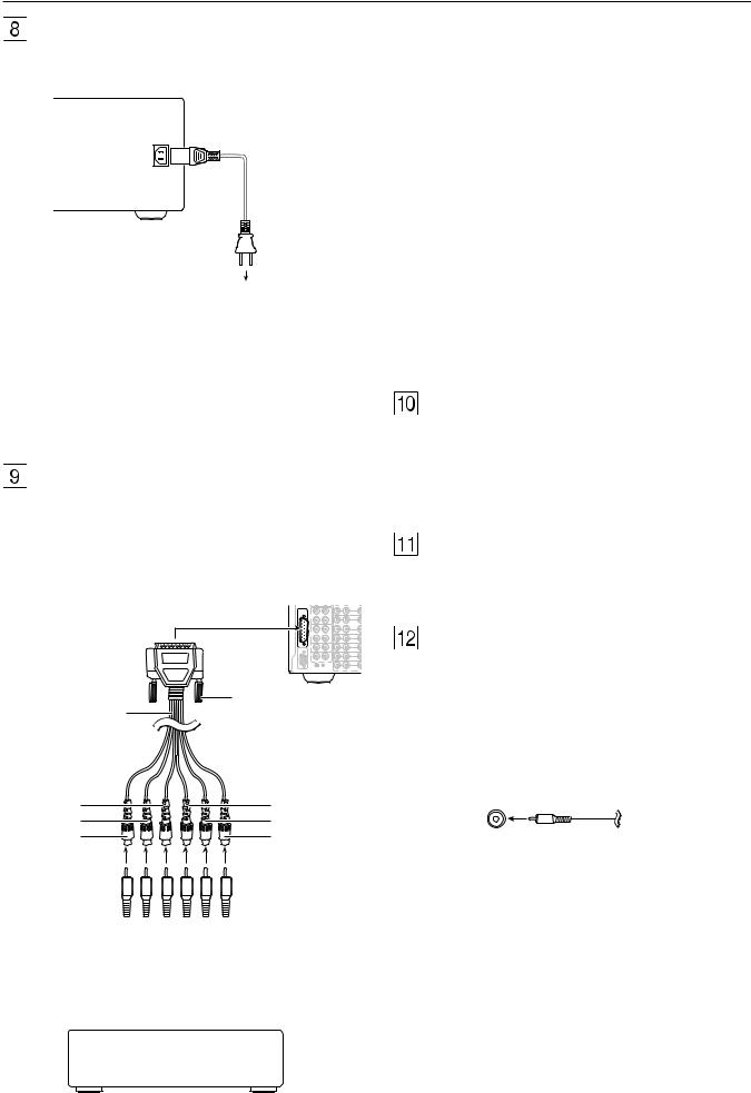
Plug the supplied power cord into this AC INLET and then into the power outlet on the wall.
Power cord (supplied)
 To an AC
wall outlet
The MULTI CHANNEL INPUT is a DB-25 port and the TXDS989 is equipped provided with a DB-25-to-RCA 6-channel cable. When making a multi-channel connection to a DVD player or MPEG decoder, connect the DB-25 end of the cable to the MULTI CHANNEL INPUT port on the TX-DS989 and RCA-type ends to the ends of the cables connected to the other component. The channel colors are shown below.
Front left (Blue)
Front right (Red)
Center (Green)
Surround left (Black)
Surround right (Yellow)
Subwoofer (Brown)
•Do not use a power cord other than the one supplied with the TX-DS989. The power cord supplied is designed for use with the TX-DS989 and should not be used with any other device.
•Never have the power cord disconnected from the TX-DS989 while the other end is plugged into the wall outlet. Doing so may cause an electric shock. Always connect by plugging into the wall outlet last and disconnect by unplugging from the wall outlet first.
MULTI CHANNEL INPUT
By connecting a DVD player, MPEG decoder, or other component that has a multi channel port, you can playback the audio with 5.1 channel or 7.1 channel output. So, be sure to prepare a cable that can properly connect the TX-DS989 to the peripheral device.
TX-DS989 MULTI CHANNEL INPUT
(DB-25-type terminal) |
CHANNEL |
|
VIDEO |
|
|
OUT |
1 |
|
MULTI |
|
|
|
INPUT TAPE |
|
|
|
1 |
IN |
|
|
|
|
VIDEO |
|
|
OUT |
2 |
|
TAPE |
IN |
VIDEO |
|
2 |
|
|
|
|
|
3 |
|
|
IN |
VIDEO |
|
CD |
|
|
|
RS 232 |
|
4 |
|
PHONO |
IN |
VIDEO |
|
|
||
|
|
|
5 |
|
R |
L |
DVD |
|
|
|
|
|
GND |
R |
L VID |
DB-25 to |
Tighten locking screws |
|
|
RCA 6-ch cable |
|
(supplied) |
|
(Green) |
(Brown) |
(Red) |
(Black) |
(Blue) |
(Yellow) |
Front left |
|
|
|
|
|
|
|
Surround right |
|
|
|
|
|
|
|
||
Front right |
|
|
|
|
|
|
|
Surround left |
|
|
|
|
|
|
|
||
Center |
|
|
|
|
|
|
|
Subwoofer |
|
|
|
|
|
|
|
||
|
|
|
|
|
|
|
|
|
|
DVD player or MPEG decoder |
|||||||
If the DVD player or MPEG decoder that you are connecting to is provided with DB-25-to-DB-25 cable, then connect that directly to the TX-DS989 and do not use the cable supplied with the TX-DS989. When connecting the cable, be sure to secure the locking screws on the DB-25 connectors.
RS 232
The RS 232 port is to be used in conjunction with an external controller to control the operation of the TX-DS989 by using an external device. The RS 232 port may also be used in the future to update the operating software of the TX-DS989 so that it will be able to support new digital audio formats and the like as they are introduced.
GND
Use this GND terminal for connecting the ground (or earth) wire if a turntable is connected. Refer to “Connecting a turntable” on page 18.
AUDIO IN/OUT
These are the analog audio inputs and outputs. There are 10 audio inputs (6 of which are linked to video inputs) and 4 audio outputs (2 of which are linked to video outputs). The audio jacks are nominally labeled for cassette tape decks, compact disc players, turntables, and DVD players. To the audio jacks for VIDEO 1 to 5, connect the audio output from VCRs, LD players, and other video components. The audio inputs and outputs require RCA-type connectors.
RCA type
•When using the PHONO jacks, remove the caps that cover then and store them safely where they will not be lost. Whenever the PHONO jacks are not in use, replace the caps on them.
•When connecting a VCR or other video component, make sure you connect the audio and video leads together (i.e., both to VIDEO 3).
•With LD players that have an AC-3RF terminal, connect the audio source to the audio inputs of VIDEO 4 because only it supports the AC-3RF settings during digital setup.
•The TX-DS989 is designed for use with turntables that use moving magnet cartridges.
14
Rear panel facilities
VIDEO IN/OUT
These are the video inputs and outputs. There are 6 video inputs and 2 video outputs and each one includes both composite video and S-video configurations. Connect VCRs, LD players, DVD players, and other video components to the video inputs. S-video sources can be viewed via the S-video or composite outputs, while composite sources can only be viewed through the composite output.
The 2 video output channels can be used to be connected to video tape recorders for making recordings.
Composite
video jack
S video jack
z connector
TX-DS989
Ex: Onkyo CD player
z connector
Ex: Onkyo cassette tape deck
•When connecting a VCR or other video component, make sure you connect the audio and video leads together (i.e., both to VIDEO 3).
•With LD players that have an AC-3RF terminal, connect the video source to the video inputs of VIDEO 4 because only it supports the AC-3RF settings during digital setup.
ZONE 2
These are the audio and video output jacks for the remote zone (Zone 2). Use these outputs to connect the remote zone. For the connection procedure, refer to “Setting up the remote zone” on page 24. These outputs are activated by the Zone 2 button on the front panel.
SPEAKERS
Seven terminals are provided for the front left, front right, front center, surround left, surround right, surround back left, and surround back right speakers. In addition to being able to reproduce the conventional 5.1-channel source input, outputs for surround back left and surround back right speakers have been added for support of the state-of-the-art THX Surround EX.
Speaker outputs are compatible with banana plug connectors .
z (RI)
By connecting the z connector as shown in the diagram below, you can use the RC-390M remote controller to operate Onkyo cassette tape decks and compact disc players that also have Onkyo’s z connectors. Simply connect a remote control cable from this connector to the z connector of the cassette tape deck or compact disc player. An z remote control cable with a 3.5- mm (1/8-inch) miniature two-conductor plug comes with every cassette tape deck and compact disc player that has an z connector.
•For remote control operation, the audio connection cables must also be connected.
•The RC-390M remote controller does not support turntables.
•If the connected component has two RI connectors, you can use either one to connect to the TX-DS989. The other one can be used to daisy chain with another component.
•For Onkyo DVD or MD players, you can control them by simply pointing the RC-390M controller directly at the component.
IR IN MAIN
If the TX-DS989 is located inside a rack or cabinet that will not allow infrared beams to reach the IR sensor, you will need to connect a remote sensor* to this input to be able to use the remote controller. Then install the remote sensor in an unblocked location where you can easily point the remote controller.
* An optional remote sensor kit is required.
IR IN ZONE 2
This jack allows you to connect a multiroom system kit so that you can use the remote controller while you are in the remote zone (Zone 2), which may be far separated from the TX-DS989.
*To be able to use the remote controller in the remote zone (Zone 2), you must connect one of the following (sold separately):
•Onkyo’s Multi-Room System Kit (IR Remote Controller Extension System).
•A multiroom A/V distribution and control system from Niles® , Xantech® , or the like
15

Example of how to connect your equipment
|
VCR |
|
|
TV monitor |
|
|
Projector |
|
|
|
Cable/Satellite |
|
|
||||
|
(VIDEO 1) |
|
|
(MONITOR OUT 1) |
|
(MONITOR OUT 2) |
|
|
(Set top box, VIDEO 3) |
|
|||||||
7. Refer to page 19 |
|
10. Refer to page 19 |
10. Refer to page 19 |
|
|
8. Refer to page 19 |
|
|
|||||||||
|
R |
L |
C |
PRE OUT |
|
VIDEO |
S VIDEO |
|
|
|
|
|
|
|
|
|
|
|
|
|
AMP |
|
|
|
|
|
|
|
|
|
|
|
|
|
|
|
|
|
IN |
1 |
|
1 |
|
|
AC-3 |
|
|
|
|
|
|
|
|
|
|
|
|
|
|
|
RF |
COMPONENT |
|
|
|
|
|
|
|||
|
|
|
|
SUB |
|
|
|
|
|
|
|
|
|
||||
|
FRONT |
|
|
MONITOR |
|
|
|
VIDEO |
|
|
|
|
|
|
|||
AM |
|
|
WOOFER |
|
|
|
|
|
|
|
|
|
|||||
|
|
OUT |
|
|
|
|
|
|
|
|
|
|
|
||||
ANT. |
|
|
|
|
|
|
|
DIGITAL |
|
INPUT 1 |
|
|
INPUT 2 |
|
|
INPU |
|
|
|
|
|
|
|
|
|
|
|
|
|
|
|||||
|
|
|
|
2 |
|
2 |
|
|
OUTPUT |
Y |
PB |
PR |
Y |
PB |
PR |
Y |
PB |
|
|
|
|
|
|
|
|
|
(COAXIAL) |
|
|
|
|
|
|
|
|
|
SURR |
|
R |
L |
|
|
|
|
|
|
|
|
|
|
|
|
|
|
|
|
|
ZONE 2 |
OUT |
|
1 |
|
|
|
|
|
|
|
|
|
|
|
|
|
|
|
|
|
DIGITAL |
|
|
|
|
|
|
|
|
||
FM |
SURR |
|
|
|
|
|
|
|
SURROUND (SURR) |
|
|
|
|
|
|||
BACK |
|
|
|
|
|
|
|
INPUT |
|
AV RECEIVER |
|
|
|||||
ANT. |
|
|
|
|
|
|
|
(COAXIAL) |
|
SPEAKERS |
|
|
|
|
|||
75 |
|
|
|
|
|
|
|
2 |
|
|
|
MODEL NO. TX-DS989 |
|
||||
|
|
|
|
|
OUT |
|
|
|
|
|
|
|
|||||
|
|
|
|
|
|
|
|
|
|
|
|
|
|
|
|
||
|
|
|
|
VIDEO |
|
|
|
BACK |
|
|
|
|
|
|
|
||
|
|
|
OUT |
|
1 |
|
|
|
|
|
|
|
|
|
|
||
MULTI |
|
|
|
|
|
|
|
L |
|
|
|
|
|
|
|
||
|
|
|
|
|
IN |
|
3 |
|
|
|
|
|
|
|
|
||
|
|
|
|
|
|
|
|
|
|
|
|
|
|
|
|||
CHANNEL |
|
|
|
|
|
|
|
|
|
|
|
|
|
|
|
|
|
INPUT |
TAPE |
|
|
|
|
|
|
|
|
|
|
|
|
|
|
|
|
|
|
|
|
|
|
|
|
|
|
|
|
|
|
|
|
|
|
|
1 |
|
IN |
|
|
|
|
|
|
|
|
|
|
|
|
|
|
|
|
|
|
|
|
OUT |
|
4 |
BACK |
|
|
|
|
|
|
|
|
|
|
|
|
VIDEO |
|
|
|
|
|
|
|
|
|
|
|||
|
|
|
|
|
|
|
|
R |
|
|
|
|
|
|
|
||
|
|
|
OUT |
|
2 |
|
|
|
|
|
|
|
|
|
|
|
|
|
|
|
|
|
|
|
|
|
|
|
|
|
|
|
|
||
|
|
|
|
|
|
IN |
|
5 |
|
|
|
|
|
|
|
|
|
|
TAPE |
|
IN |
|
|
|
|
|
|
|
|
|
|
|
|
|
|
|
2 |
|
VIDEO |
|
|
|
DIGITAL |
L |
|
|
|
|
|
|
|
||
|
|
|
|
|
|
|
|
|
|
|
|
|
|
||||
|
|
|
|
|
3 |
IN |
|
|
OUTPUT |
|
|
|
|
|
|
|
|
|
|
|
|
|
|
|
|
(OPTICAL) |
|
|
|
|
|
|
|
|
|
|
CD |
|
IN |
VIDEO |
|
|
1 |
|
|
|
|
|
|
|
|
|
|
|
|
|
IN |
|
|
|
|
|
|
|
|
|
|
|
|||
RS 232 |
|
|
|
4 |
|
|
|
|
|
|
|
|
|
|
|
||
|
|
|
|
|
|
|
DIGITAL |
|
|
|
|
|
|
|
|
||
|
|
|
|
|
|
|
|
|
|
|
|
|
|
|
|
|
|
|
PHONO |
|
IN |
VIDEO |
|
|
2 |
INPUT |
|
|
|
|
|
|
|
|
|
|
|
|
|
IN |
|
|
(OPTICAL) |
R |
|
|
|
|
|
|
|
||
|
|
|
|
|
5 |
|
|
|
|
|
|
|
|
|
|
||
|
|
|
|
|
|
|
|
|
|
|
|
|
|
|
|
|
|
|
R |
L |
|
|
DVD |
|
|
3 |
|
|
|
|
|
|
|
|
|
|
|
|
|
|
|
|
CAUTION:SPEAKER IMPEDANCE |
|
|
|
|
|
|||||
|
|
|
|
|
IN |
|
|
|
|
|
|
|
|||||
|
|
|
|
|
|
|
|
|
|
|
|
|
|||||
|
|
|
|
|
6 OHMS MIN. PER EACH |
GND |
R |
L |
VIDEO |
S VIDEO |
SPEAKER TERMINAL |
|
Turntable (PHONO)
1. Refer to page 18
CD player (CD)
2. Refer to page 18
Tape deck, DAT, MD recorder, CD-R (TAPE 2)
3. Refer to page 18
DAT deck, CD-R, |
|
|
Analog signal |
DVD player |
|
LD player |
MD recorder |
|
|
|
|||
|
|
|
(DVD) |
|
(VIDEO 4) |
|
(TAPE 1) |
|
|
Digital signal |
|
||
|
|
5. Refer to page 18 |
|
6. Refer to page 18 |
||
4. Refer to page 18 |
|
|
flow |
|
||
|
|
|
|
|
||
|
|
|
|
|
|
|
|
|
|
|
|
|
|
16
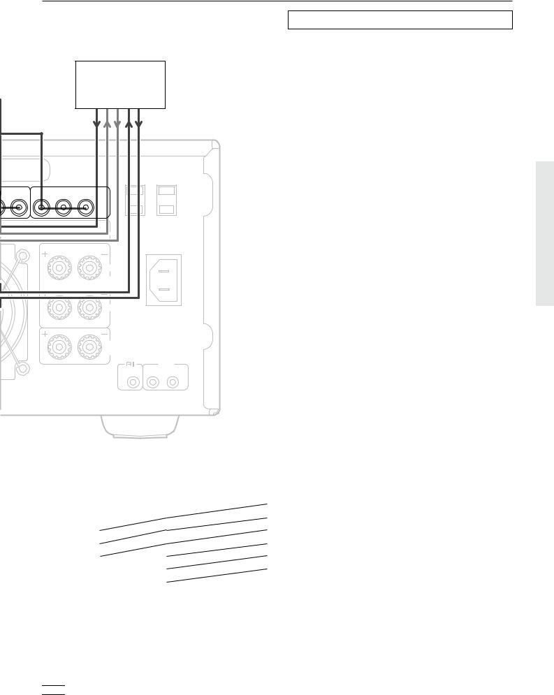
Example of how to connect your equipment
DVD recorder
or other digital video recording device
9. Refer to page 19
|
|
|
|
AC 120V 60Hz |
|
|
|
|
SWITCHED |
|
|
|
AC OUTLETS TOTAL 120W 1A MAX. |
|
T 3 |
|
OUTPUT |
|
|
PR |
Y |
PB |
PR |
|
|
|
|
L |
|
|
|
|
FRONT |
AC |
|
|
|
INLET |
|
|
|
|
SPEAKERS |
|
|
|
|
|
|
|
|
|
R |
|
|
|
|
|
CAUTION: |
|
|
|
|
SPEAKER IMPEDANCE |
6 OHMS MIN. PER EACH CENTER SPEAKER TERMINAL
SPEAKER
IR IN
MAIN ZONE 2
Standard connections
Here is explanation of how to connect the main components to the TX-DS989 in the standard manner. There are many ways that any one component can be connected, and it is up to you to decide which method best fits your situation. The directions given here are only one option and should only be thought of as such. It is best to fully understand the nature of each connector and terminal as well as each of your components and their features to ascertain which method of connection is best.
•Be sure to always refer to the instruction manual that came with the component that you are connecting.
•Do not plug in the power cord until all connections have been made.
•For input jacks, red connectors (marked R) are used for the right channel, white connectors (marked L) are used for the left channel, and yellow connectors (marked V) are used for video connection.
•Insert all plugs and connectors securely. Improper connections can result in noise, poor performance, or damage to the equipment.
•Do not bind audio connection cables with power cords and speaker cables. Doing so may adversely affect the sound quality.
For a detailed explanation of how to connect the devices given below, refer to the pages listed.
Speakers: See page 20
Radio antenna: See page 22
Enjoying the TX-DS989 from a remote room (Zone 2):
See page 24
Graphic equalizer: See page 26
Power amplifier: See page 26
Default setting
Input source |
Digital input |
Component video |
|
|
|
CD |
COAXIAL 1 |
|
|
|
|
PHONO |
|
|
|
|
|
FM |
|
|
|
|
|
AM |
|
|
|
|
|
TAPE 1 |
OPTICAL 1 |
|
|
|
|
TAPE 2 |
OPTICAL 2 |
|
|
|
|
DVD |
OPTICAL 3 |
COMPONENT VIDEO 1 |
|
|
|
VIDEO 1 |
---- |
---- |
|
|
|
VIDEO 2 |
COAXIAL 2 |
COMPONENT VIDEO 2 |
|
|
|
VIDEO 3 |
COAXIAL 3 |
COMPONENT VIDEO 3 |
|
|
|
VIDEO 4 |
COAXIAL 4 |
---- |
|
|
|
VIDEO 5 |
COAXIAL 5 |
---- |
|
|
|
---- : No setting  : No applicable
17

Example of how to connect your equipment
Connecting your audio components
Below is an example of how you can connect your audio components to the TX-DS989. Refer to the diagram on pages 16 and 17 for the following connection examples.
1. Connecting a turntable
Using an RCA-type audio connection cable, connect the output terminal on the turntable to the PHONO IN jacks on the TXDS989. Make sure that you properly connect the left channel to the L jack and the right channel to the R jack.
Note:
The TX-DS989 is designed for use with moving magnet cartridges. For proper operation, connect a ground (or earth) wire to the GND terminal. For some turntables, however, connecting the ground wire may cause increased noise, and in such a case, a ground wire is not necessary and should not be connected.
2. Connecting a compact disc player
Using an RCA-type audio connection cable, connect the output terminal on the compact disc player to the CD IN jacks on the TXDS989. Make sure that you properly connect the left channel to the L jack and the right channel to the R jack.
If the compact disc player has a digital output jack as well, be sure to also connect it to either a DIGITAL INPUT (COAXIAL) or DIGITAL INPUT (OPTICAL) jack on the TX-DS989 depending on the type of connector on the compact disc player.
With the initial settings of the TX-DS989, the CD input source is set for digital input at the COAXIAL 1 jack. If the digital connection is made at a different jack, this must be changed at the OSD Menu: Input Setup → Digital Setup → Digital Input (see page 34).
3.Connecting a cassette tape deck, MD recorder, DAT deck, or CD recorder
Using an RCA-type audio connection cable, connect the output terminals (PLAY) of the device to the TAPE 2 IN jacks on the TXDS989 and the input terminals (REC) to the TAPE 2 OUT jacks. Make sure that you properly connect the left channel to the L jack and the right channel to the R jack.
If the device has a digital output jack as well, be sure to also connect it to either a DIGITAL INPUT (COAXIAL) or DIGITAL INPUT (OPTICAL) jack on the TX-DS989 depending on the type of connector on the device.
With the initial settings of the TX-DS989, the TAPE 2 input source is set for digital input at the OPTICAL 2 jack. If the digital connection is made at a different jack, this must be changed at the OSD Menu: Input Setup → Digital Setup → Digital Input (see page 34).
If the device also has a digital input jack, it can be connected to the DIGITAL OUTPUT (COAXIAL) or DIGITAL OUTPUT (OPTICAL) jack on the TX-DS989 for recording of the signal from the input source selected at the TX-DS989.
4.Connecting an MD recorder, DAT deck, or CD recorder
Using an RCA-type audio connection cable, connect the output terminals (PLAY) of the device to the TAPE 1 IN jacks on the TXDS989 and the input terminals (REC) to the TAPE 1 OUT jacks. Make sure that you properly connect the left channel to the L jack and the right channel to the R jack.
If the device has a digital output jack as well, be sure to also connect it to either a DIGITAL INPUT (COAXIAL) or DIGITAL INPUT (OPTICAL) jack on the TX-DS989 depending on the type of connector on the device.
With the initial settings of the TX-DS989, the TAPE 1 input source is set for digital input at the OPTICAL 1 jack. If the digital connection is made at a different jack, this must be changed at the OSD Menu: Input Setup → Digital Setup → Digital Input (see page 34).
If the device also has a digital input jack, it can be connected to the DIGITAL OUTPUT (COAXIAL) or DIGITAL OUTPUT (OPTICAL) jack on the TX-DS989 for recording of the signal from the input source selected at the TX-DS989.
Connecting your video components
Below is an example of how you can connect your video components to the TX-DS989. Refer to the diagram on pages 16 and 17 for the following connection examples.
The flow of the video signals is as follows: the signal that comes in from VIDEO IN is sent to VIDEO OUT, the signal that comes in from S-VIDEO IN is sent to S-VIDEO OUT and VIDEO OUT, and the signal that comes in from COMPONENT VIDEO IN is sent to COMPONENT VIDEO OUT.
If only the video connection for the MONITOR OUT is made, even if the input from each source component is through a component video connection, the picture will not appear. If only the S-video connection for the MONITOR OUT is made, the picture will not appear.
5. Connecting a DVD player
Using an RCA-type video connection cable, connect the video output terminal (composite) on the DVD player to the DVD VIDEO IN jack on the TX-DS989. If there is an S-video output terminal on the DVD player, connect it to the DVD S VIDEO IN jack using an S-video cable. If the DVD player has component video outputs, connect them to one of the COMPONENT VIDEO INPUT jacks.
Using an RCA-type audio connection cable, connect the audio output terminal on the DVD player to the audio DVD IN jacks on the TX-DS989. Make sure that you properly connect the left channel to the L jack and the right channel to the R jack.
If the DVD player has a digital output jack as well, be sure to also connect it to either a DIGITAL INPUT (COAXIAL) or DIGITAL INPUT (OPTICAL) jack on the TX-DS989 depending on the type of connector on the DVD player.
With the initial settings of the TX-DS989, the DVD input source is set for digital input at the OPTICAL 3 jack. If the digital connection is made at a different jack, this must be changed at the OSD Menu: Input Setup → Digital Setup → Digital Input (see page 34).
18

Example of how to connect your equipment
6. Connecting a LD player
Using an RCA-type video connection cable, connect the video output terminal (composite) on the LD player to the VIDEO 4 IN jack on the TX-DS989. If there is an S-video output terminal on the LD player, connect it to the S VIDEO 4 IN jack using an S- video cable.
If the LD player has an AC-3RF output, connect it to the AC-3RF jack on the TX-DS989. If this connection is made, “AC-3RF” must be set in the OSD Menu: Input Setup → Digital Setup → Digital Format (see page 34).
Using an RCA-type audio connection cable, connect the audio output terminal on the LD player to the audio VIDEO 4 IN jacks on the TX-DS989. Make sure that you properly connect the left channel to the L jack and the right channel to the R jack.
If the LD player has a digital output jack as well, be sure to also connect it to either a DIGITAL INPUT (COAXIAL) or DIGITAL INPUT (OPTICAL) jack on the TX-DS989 depending on the type of connector on the LD player.
With the initial settings of the TX-DS989, the VIDEO 4 input source is set for digital input at the COAXIAL 4 jack. If the digital connection is made at a different jack, this must be changed at the OSD Menu: Input Setup → Digital Setup → Digital Input (see page 34).
7. Connecting a video cassette recorder
Using an RCA-type video connection cable, connect the video output terminal (composite) on the video cassette recorder to the VIDEO 1 IN jacks on the TX-DS989 and video input terminal to the VIDEO 1 OUT jacks. If there is an S-video input/output terminal on the video cassette recorder, connect it to the S VIDEO 1 IN/OUT jack using an S-video cable. If the video cassette recorder has component video outputs, connect them to one of the COMPONENT VIDEO INPUT jacks.
Using an RCA-type audio connection cable, connect the audio output terminal on the video cassette recorder to the same VIDEO 1 IN audio jacks on the TX-DS989 and audio input terminal to the VIDEO 1 OUT audio jacks. Make sure that you properly connect the left channel to the L jack and the right channel to the R jack.
8. Connecting a satellite tuner or television
Using an RCA-type video connection cable, connect the video output terminal (composite) on the satellite tuner or television to the VIDEO 3 IN jacks on the TX-DS989. If there is an S-video output terminal on the satellite tuner or television, connect it to the S VIDEO 3 IN jack using an S-video cable. If the satellite tuner or television has component video outputs, connect them to one of the COMPONENT VIDEO INPUT jacks.
Using an RCA-type audio connection cable, connect the audio output terminal on the satellite tuner or television to the same VIDEO 3 IN audio jacks on the TX-DS989. Make sure that you properly connect the left channel to the L jack and the right channel to the R jack.
If the satellite tuner or television has a digital output jack as well, be sure to also connect it to either a DIGITAL INPUT (COAXIAL) or DIGITAL INPUT (OPTICAL) jack on the TXDS989 depending on the type of connector on the set top box or television.
With the initial settings of the TX-DS989, the VIDEO 3 input source is set for digital input at the COAXIAL 3 jack. If the digital connection is made at a jack different from the initial settings, this must be changed at the OSD Menu: Input Setup → Digital Setup → Digital Input (see page 34).
9.Connecting a DVD recorder or other digital video recording device
Using an RCA-type video connection cable, connect the video output terminal (composite) on the device to the VIDEO 2 IN jacks on the TX-DS989 and video input terminal to the VIDEO 1 OUT jacks. If there is an S-video input/output terminal on the device, connect it to the S VIDEO 2 IN/OUT jack using an S-video cable. If the device has component video outputs, connect them to one of the COMPONENT VIDEO INPUT jacks.
Using an RCA-type audio connection cable, connect the audio output terminal on the device to the same VIDEO 2 IN audio jacks on the TX-DS989 and audio input terminal to the VIDEO 1 OUT audio jacks. Make sure that you properly connect the left channel to the L jack and the right channel to the R jack.
If the device has a digital output jack as well, be sure to also connect it to either a DIGITAL INPUT (COAXIAL) or DIGITAL INPUT (OPTICAL) jack on the TX-DS989 depending on the type of connector on the device.
With the initial settings of the TX-DS989, the VIDEO 2 input source is set for digital input at the COAXIAL 2 jack. If the digital connection is made at a jack different from the initial settings, this must be changed at the OSD Menu: Input Setup → Digital Setup
→Digital Input (see page 34).
If the device also has a digital input jack, it can be connected to the DIGITAL OUTPUT (COAXIAL) or DIGITAL OUTPUT (OPTICAL) jack on the TX-DS989 for recording of the signal from the input source selected at the TX-DS989.
10. Connecting a television monitor or projector
Using an RCA-type video connection cable, connect the video input terminal (composite) on the monitor to one of the MONITOR OUT jacks on the TX-DS989. If there is an S-video input terminal on the monitor, connect it to the S VIDEO MONITOR OUT jack using an S-video cable. If the device has component video inputs, connect them to the COMPONENT VIDEO OUTPUT jacks.
Note that the OSD Menu will not be displayed on the monitor connected to MONITOR OUT 2. This allows you to connect large screens or projectors to MONITOR OUT 2 and use a smaller television connected to MONITOR OUT 1 just to make settings in the OSD Menu.
19
Connecting speakers
Before connecting the speakers, place them correctly by consulting the instruction manuals that came with them.
For surround playback, the configuration and placement of your speakers are very important.
For THX surround EX playback, we recommend that you use a THX speaker system that is certified by Lucasfilm Ltd.
Ideal speaker configuration
•Front right and left speakers
•Center speaker
Produces a rich sound image by serving as a sound source for the front right and left speakers and enhancing the sonic movement.
•Surround right and left speakers
Adds three-dimensional sonic movement and produces environmental sound associated with the background and effect sound for each scene.
•Surround back right and left speakers
Required for enjoying THX Surround EX audio.
•Subwoofer
Produces powerful and heavy bass.
Minimum speaker configuration for surround sound playback
•Front right and left speakers
•Surround right and left speakers
The sound recorded for the center speaker and the subwoofer will be properly distributed to the front right and left speakers and the surround right and left speakers for optimized surround playback.
Speaker placement
Ideal speaker placement varies depending on the size of your room and the wall coverings. Here, only typical example of speaker placement and recommendations are shown.
Important points regarding speaker placement
Front left and right speakers and center speaker
•Place these three speakers at the same height from the floor.
•Place each speaker so that sound is aimed at the location of the listener’s ears when at the listening position.
Surround left and right speakers
•Place these speakers so that their height is 1 meter higher than that of the listener’s ears.
Surround back left and right speakers
•These speakers are required for enjoying THX Surround EX audio.
•Place these speakers behind the listener so that the angle between each speaker and the listener is approximately 30 degrees.
•Place these speakers so that their height is 1 meter higher than that of the listener’s ears.
10
30° 30°
8 |
|
9 |
|
|
|
Subwoofer
A subwoofer is recommended for the highest bass effect.
|
|
1 |
|
|
|
1 |
|
2 |
3 |
4 |
5 |
2 |
3 |
4 |
5 |
|
|
|
|
6 |
7 |
6 |
7 |
10 |
10 |
|
8 |
|
9 |
|
|
|
8 |
|
9 |
|
|
|
|
|
|
|
|
|
|
|
|
1 |
TV or screen |
6 |
Surround left speaker |
2 |
Front left speaker |
7 |
Surround right speaker |
3 |
Subwoofer |
8 |
Surround back left speaker |
4 |
Center speaker |
9 |
Surround back right speaker |
5 |
Front right speaker |
10 |
Listening position |
Most dipoles have an arrow on them to indicate their orientation towards the screen. So for the side dipoles, the arrows point forward. For the back dipoles, the arrows should point towards each other to achieve the correct acoustical phasing in the room.
20
Connecting speakers
Connecting speakers
Notes:
•The TX-DS989 is designed to produce optimum sound quality when speakers with impedances within the specified ranges are connected. Check the following information and choose speakers with appropriate impedances for the connections.
CAUTION:
SPEAKER IMPEDANCE
6 Ω min. per each speaker terminal.
•When you are using only one speaker or when you wish to listen to monaural (mono) sound, a single speaker should never be connected in parallel to both the right and leftchannel terminals simultaneously.
NO!
+ – |
– + |
+ – |
– + |
R |
L |
R |
L |
Connecting the speaker cable
1.Strip away 5/8" of wire insulation.
2.Twist wire ends very tight.
3.Unscrew
4.Insert wire
5.Screw
1 |
5/8" |
2 |
3 |
4 |
5 |
Connecting a subwoofer
• To prevent damage to |
|
Use the PRE OUT SUBWOOFER jack to connect a subwoofer |
|
circuitry, never short- |
NO! |
with a built-in power amplifier. If your subwoofer does not have a |
|
built-in amplifier, connect an amplifier to the PRE OUT |
|||
circuit the positive (+) and |
|
||
negative (–) speaker wire. |
|
SUBWOOFER jack and the subwoofer to the amplifier. The |
|
|
|
output to PRE OUT SUBWOOFER 1 and PRE OUT |
|
|
|
SUBWOOFER 2 is the same. |
|
|
Surround |
|
Surround |
|
Surround |
|
Surround |
Subwoofer |
|
left |
|
back left |
|
back right |
|
right |
|
|
speaker |
|
speaker |
|
speaker |
|
speaker |
|
|
|
|
|
|
|
|
|
– + |
– + |
+ |
– |
+ |
– |
|
R |
L |
C |
PRE OUT |
VIDEO |
S VIDEO |
|
|
AMP |
|
|
|
|
|
|
IN |
|
1 |
1 |
|
|
|
|
|
|
||
|
FRONT |
|
|
SUB |
MONITOR |
|
AM |
|
|
WOOFER |
|||
ANT. |
|
|
|
|
OUT |
|
|
|
|
|
2 |
2 |
|
|
SURR |
|
R |
L |
|
|
|
|
|
|
ZONE 2 |
OUT |
1 |
|
|
|
|
|
||
FM |
SURR |
|
|
|
|
|
ANT. |
BACK |
|
|
|
|
|
75 |
|
|
|
|
OUT |
2 |
|
|
|
|
|
||
|
|
|
|
VIDEO |
|
|
MULTI |
|
OUT |
|
1 |
|
|
|
|
|
|
IN |
3 |
|
CHANNEL |
|
|
|
|
|
|
INPUT |
TAPE |
|
|
|
|
|
|
|
|
|
|
|
|
|
1 |
IN |
|
|
|
|
|
|
|
|
|
OUT |
4 |
|
|
|
|
VIDEO |
|
|
|
|
OUT |
|
2 |
|
|
|
|
|
|
|
IN |
5 |
|
TAPE |
IN |
|
|
|
|
|
2 |
|
VIDEO |
|
|
|
|
|
|
|
IN |
|
|
|
|
|
|
3 |
|
|
|
|
|
|
|
|
|
|
CD |
IN |
|
VIDEO |
|
1 |
|
|
|
IN |
|
||
RS 232 |
|
|
4 |
|
||
|
|
|
|
|
||
|
PHONO |
IN |
|
VIDEO |
|
2 |
|
|
|
|
IN |
|
|
|
|
|
|
5 |
|
|
|
|
|
|
|
|
|
|
R |
L |
|
DVD |
|
3 |
|
|
|
|
|
||
|
|
|
|
IN |
|
|
|
|
|
|
|
|
|
|
GND |
|
R |
L |
VIDEO |
S VIDEO |
|
AC 120V 60Hz |
|
SWITCHED |
AC-3 |
AC OUTLETS TOTAL 120W 1A MAX. |
RF |
COMPONENT |
|
VIDEO |
DIGITAL |
Y |
INPUT 1 |
PR |
|
INPUT 2 |
|
|
INPUT 3 |
|
|
OUTPUT |
|
OUTPUT |
PB |
Y |
PB |
PR |
Y |
PB |
PR |
Y |
PB |
PR |
||
(COAXIAL) |
|
|
|
|
|
|
|
|
|
|
|
|
DIGITAL |
SURROUND (SURR) |
INPUT |
|
(COAXIAL) |
SPEAKERS |
BACK |
|
L |
|
BACK
R
DIGITAL L OUTPUT
(OPTICAL)
DIGITAL
INPUT
(OPTICAL) R
CAUTION:SPEAKER IMPEDANCE
6 OHMS MIN. PER EACH SPEAKER TERMINAL
AV RECEIVER
MODEL NO. TX-DS989
L
FRONT SPEAKERS
R
CENTER SPEAKER
AC
INLET
CAUTION:
SPEAKER IMPEDANCE
6 OHMS MIN. PER EACH SPEAKER TERMINAL
IR IN
MAIN ZONE 2
+ |
– |
+ |
– |
+ |
– |
||
Front left |
|
Center |
|
Front right |
|||
speaker |
|
speaker |
|
speaker |
|||
|
|
|
|
|
|
|
|
21
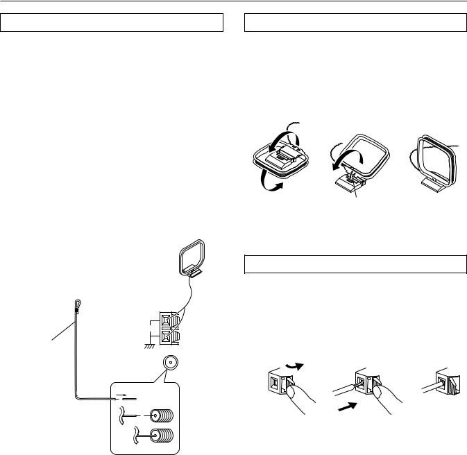
Connecting antennas
Connecting the included antennas
Connecting the FM indoor antenna:
The FM indoor antenna is for indoor use only. During use, extend the antenna and move it in various directions until the clearest signal is received. Fix it with push pins or similar implements in the position that will cause the least amount of distortion.
If the reception is not very clear with the attached FM indoor antenna, the use of an outdoor antenna is recommended.
Connecting the AM loop antenna:
The AM loop antenna is for indoor use only. Set it in the direction and position where you receive the clearest sound. Put it as far away as possible from the TX-DS989, televisions, speaker cables, and power cords.
When reception is not satisfactory with the attached AM loop antenna alone, connection of an outdoor antenna is recommended.
(indoor) AM loop antenna
Assembling the AM loop antenna
Assemble the loop antenna as shown in the illustration.
•Refer to the next page for details on connecting the AM loop antenna.
Insert into the hole.
U.S. and Canadian models
FM antenna
ANTENNA |
AM |
FM 75
Connecting the AM antenna cable
1.Press down the lever.
2.Insert the wire into the hole.
3.Release the lever.
1 |
2 |
3 |
Strip away the insulation from the end of the cable, then fully insert the stripped end of the cable.
22
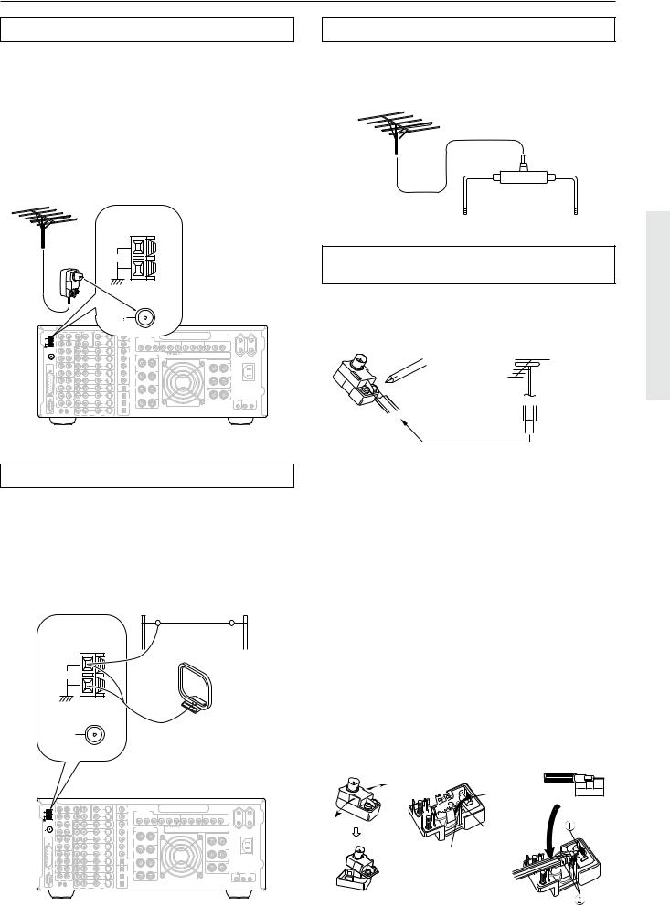
Connecting antennas
Connecting an FM outdoor antenna
Please make sure that you follow the considerations:
•Keep the antenna away from noise sources (neon signs, busy roads, etc.).
•It is dangerous to put the antenna close to power lines. Keep it well away from power lines, transformers, etc.
•To avoid the risk of lightning and electrical shock, grounding is necessary. Follow item 14 of the “Important Safeguards” on page 2 when you install the outdoor antenna.
Directional linkage
Do not use the same antenna for both FM and TV (or VCR) reception since the FM and TV (or VCR) signals can interfere with each other. If you must use a common FM/TV (or VCR) antenna, use a directional linkage type splitter.
ANTENNA
AM
|
|
|
|
|
|
FM |
|
|
|
|
|
|
|
|
|
|
75 |
|
|
|
|
|
R |
L |
C |
PRE OUT |
VIDEO |
S VIDEO |
|
|
|
|
|
|
|
AMP |
|
|
|
|
|
|
|
|
|
|
IN |
1 |
1 |
|
AC-3 |
COMPONENT |
|
|
|
|
|
|
SUB |
|
|
RF |
|
||
AM |
FRONT |
|
|
WOOFER |
OUT |
|
DIGITAL |
|
|
|
ANT. |
|
|
|
|
|
|
Y |
INPUT 1 |
P |
|
|
|
|
|
2 |
2 |
|
OUTPUT |
P |
||
|
|
|
|
|
|
|
(COAXIAL) |
|
|
|
|
SURR |
|
R |
L |
|
|
|
|
|
|
|
|
|
|
ZONE 2 |
OUT |
1 |
DIGITAL |
|
|
|
FM |
SURR |
|
|
|
|
|
SURROUND (SURR) |
|||
ANT. |
BACK |
|
|
|
|
|
INPUT |
|||
75 |
|
|
|
|
OUT |
2 |
(COAXIAL) |
|
SPEAKERS |
|
|
|
|
|
|
|
|
|
|
||
|
|
|
|
VIDEO |
|
|
BACK |
|
|
|
|
|
|
OUT |
1 |
|
|
|
|
||
MULTI |
|
|
|
|
IN |
3 |
|
L |
|
|
CHANNEL |
|
|
|
|
|
|
|
|
||
INPUT |
TAPE |
|
|
|
|
|
|
|
|
|
|
1 |
|
IN |
|
|
|
|
|
|
|
|
|
|
|
|
OUT |
4 |
|
|
|
|
|
|
|
|
VIDEO |
|
|
BACK |
|
|
|
|
|
|
OUT |
2 |
|
|
|
R |
|
|
|
|
|
|
|
IN |
5 |
|
|
|
|
|
TAPE |
|
IN |
VIDEO |
|
|
DIGITAL |
L |
|
|
|
2 |
|
|
|
|
|
|
|||
|
|
|
|
3 |
IN |
|
OUTPUT |
|
|
|
|
|
|
|
|
|
(OPTICAL) |
|
|
|
|
|
CD |
|
IN |
VIDEO |
|
1 |
|
|
|
|
|
|
|
IN |
|
|
|
|
|
||
RS 232 |
|
|
|
4 |
|
|
DIGITAL |
|
|
|
|
|
|
|
|
|
|
|
|
|
|
|
PHONO |
|
IN |
VIDEO |
|
2 |
INPUT |
|
|
|
|
|
|
|
IN |
|
(OPTICAL) |
R |
|
|
|
|
|
|
|
5 |
|
|
|
|
|
|
|
R |
L |
|
DVD |
|
3 |
|
|
|
|
|
|
|
|
IN |
CAUTION:SPEAKER IMPEDANCE |
|||||
|
|
|
|
|
|
|||||
|
|
|
|
|
|
|
|
6 OHMS MIN. PER EACH |
||
|
GND |
|
R |
L |
VIDEO |
S VIDEO |
|
SPEAKER TERMINAL |
||
|
|
|
|
|
|
|||||
AC OUTLETS
AC 230V 50Hz
SWITCHED
TOTAL 120W MAX.
|
INPUT 2 |
|
|
INPUT 3 |
|
|
OUTPUT |
|
Y |
P |
P |
Y |
P |
P |
Y |
P |
P |
AV RECEIVER
MODEL NO. TX-DS989
L
FRONT
SPEAKERS
R
CENTER
SPEAKER
AC
INLET
CAUTION:
SPEAKER IMPEDANCE
6 OHMS MIN. PER EACH SPEAKER TERMINAL
IR IN
MAIN ZONE 2
To receiver |
To TV (or VCR) |
Connecting the antenna cable to the 75/300 Ω antenna adapter (not included)
Connecting the 300 Ω ribbon wire:
Loosen the screws and wrap the wire around these screws. Then tighten the screws with a screwdriver.
Outdoor antenna
300 Ω ribbon wire
Connecting an AM outdoor antenna
An outdoor antenna will be more effective if it is stretched horizontally above a window or outside.
•Do not remove the AM loop antenna.
•To avoid the risk of lightning and electrical shock, grounding is necessary. Follow item 14 of the “Important Safeguards” on page 2 when you install the outdoor antenna.
Outdoor antenna
ANTENNA
AM
(Indoor)
AM loop antenna
FM 75
|
R |
L |
C |
PRE OUT |
VIDEO |
S VIDEO |
|
|
|
|
|
|
|
|
|
|
|
|
|
|
AC OUTLETS |
|
|
|
|
AMP |
|
|
|
|
|
|
|
|
|
|
|
|
|
|
|
|
|
AC 230V 50Hz |
|
|
|
|
IN |
1 |
|
1 |
|
AC-3 |
|
|
|
|
|
|
|
|
|
|
|
|
SWITCHED |
|
|
|
|
|
SUB |
|
|
|
RF |
|
COMPONENT |
|
|
|
|
|
|
|
|
|
TOTAL 120W MAX. |
|
|
AM |
FRONT |
|
|
WOOFER |
|
OUT |
|
DIGITAL |
|
|
|
|
|
|
|
|
|
|
|
|
|
|
ANT. |
|
|
|
|
|
|
|
|
|
INPUT 1 |
|
|
INPUT 2 |
|
|
INPUT 3 |
|
|
OUTPUT |
|
|
|
|
|
|
|
2 |
|
2 |
|
OUTPUT |
|
Y |
P |
P |
Y |
P |
P |
Y |
P |
P |
Y |
P |
P |
|
|
|
|
|
|
|
|
|
(COAXIAL) |
|
|
|
|
|
|
|
|
|
|
|
|
|
|
|
SURR |
|
R |
L |
|
|
|
|
|
|
|
|
|
|
|
|
|
|
|
|
|
|
|
|
|
|
ZONE 2 |
|
OUT |
1 |
DIGITAL |
|
|
|
|
|
|
|
|
|
|
|
|
|
|
FM |
SURR |
|
|
|
|
|
|
|
SURROUND (SURR) |
|
|
|
|
|
|
|
|
|
|
|||
ANT. |
BACK |
|
|
|
|
|
|
INPUT |
|
|
AV RECEIVER |
|
|
|
|
|
|
|
||||
75 |
|
|
|
|
|
OUT |
2 |
(COAXIAL) |
|
|
SPEAKERS |
|
|
MODEL NO. TX-DS989 |
|
|
|
|
|
|
||
|
|
|
|
|
|
|
|
|
|
|
|
|
|
|
|
|
|
|||||
|
|
|
|
VIDEO |
|
|
|
BACK |
|
|
|
|
|
|
|
|
|
|
|
|
|
|
|
|
|
OUT |
1 |
|
|
|
|
|
|
|
|
|
|
|
|
|
|
|
|
||
MULTI |
|
|
|
|
|
IN |
3 |
|
L |
|
|
|
|
|
|
|
|
|
|
|
|
|
CHANNEL |
|
|
|
|
|
|
|
|
|
|
|
|
|
|
|
|
|
|
L |
|
||
INPUT |
TAPE |
|
|
|
|
|
|
|
|
|
|
|
|
|
|
|
|
|
|
|
|
|
|
1 |
|
IN |
|
|
|
|
|
|
|
|
|
|
|
|
|
|
|
|
|
FRONT |
AC |
|
|
|
|
|
|
OUT |
4 |
BACK |
|
|
|
|
|
|
|
|
|
|
|
SPEAKERS |
INLET |
|
|
|
|
|
VIDEO |
|
|
|
|
|
|
|
|
|
|
|
|
|
|
|
|
||
|
|
|
OUT |
2 |
|
|
|
|
R |
|
|
|
|
|
|
|
|
|
|
|
|
|
|
|
|
|
|
|
IN |
5 |
|
|
|
|
|
|
|
|
|
|
|
|
|
R |
|
|
TAPE |
|
|
|
|
|
|
|
|
|
|
|
|
|
|
|
|
|
|
|
|
|
|
2 |
|
IN |
VIDEO |
|
|
|
DIGITAL |
L |
|
|
|
|
|
|
|
|
|
|
|
|
CAUTION: |
|
|
|
|
|
IN |
|
|
|
|
|
|
|
|
|
|
|
|
|
||||
|
|
|
|
3 |
|
|
|
OUTPUT |
|
|
|
|
|
|
|
|
|
|
|
|
|
SPEAKER IMPEDANCE |
|
|
|
|
|
|
|
|
(OPTICAL) |
|
|
|
|
|
|
|
|
|
|
|
|
|
6 OHMS MIN. PER EACH |
|
CD |
|
IN |
VIDEO |
|
|
1 |
|
|
|
|
|
|
|
|
|
|
|
|
|
CENTER |
SPEAKER TERMINAL |
|
|
|
|
IN |
|
|
|
|
|
|
|
|
|
|
|
|
|
|
SPEAKER |
|
||
RS 232 |
|
|
|
4 |
|
|
|
DIGITAL |
|
|
|
|
|
|
|
|
|
|
|
|
|
|
|
PHONO |
|
IN |
VIDEO |
|
|
2 |
INPUT |
|
|
|
|
|
|
|
|
|
|
|
|
|
IR IN |
|
|
|
|
|
IN |
|
(OPTICAL) |
R |
|
|
|
|
|
|
|
|
|
|
|
|
MAIN ZONE 2 |
|
|
|
|
|
5 |
|
|
|
|
|
|
|
|
|
|
|
|
|
|
|
|
|
|
|
R |
L |
|
DVD |
|
|
3 |
|
|
|
|
|
|
|
|
|
|
|
|
|
|
|
|
|
|
|
|
IN |
CAUTION:SPEAKER IMPEDANCE |
|
|
|
|
|
|
|
|
|
|
||||||
|
|
|
|
|
|
|
|
|
|
6 OHMS MIN. PER EACH |
|
|
|
|
|
|
|
|
|
|
||
|
GND |
|
R |
L |
VIDEO |
S VIDEO |
|
|
|
SPEAKER TERMINAL |
|
|
|
|
|
|
|
|
|
|
||
Connecting the coaxial cable:
1.With your fingernail, or a small screwdriver, press the stoppers of the 75/300 Ω antenna adapter outward and remove the cover.
2.Remove the transformer wire A from slit B and insert it into slit C.
3.Prepare the coaxial cable as shown in the diagram.
4.Connect the 75/300 Ω antenna adapter to the coaxial cable.
1 Insert the end of the cable.
2 Clamp it in place with pliers.
5.Reinstall the cover.
1 |
2 |
3, 4 |
|
|
|
|
|
|
|
|||
|
|
|
|
|
|
|
|||
|
|
|
|
|
|
|
6 |
3 |
6 |
Slit B |
mm mm mm |
|||
|
15mm |
|||
|
|
|||
Wire A
Slit C
23
 Loading...