


TX-8390
Table of contents
 Loading...
NETWORK STEREO RECEIVER
En
TX-8390
Instruction Manual
Table of contents ≫
Connections ≫
- Connecting Speakers ≫
Playback ≫
Setup ≫
Troubleshooting ≫
Appendix ≫
Supplementary Information ≫
Front Panel≫ Rear Panel≫ Remote≫
Contents ≫ Connections ≫ Playback ≫ Setup
≫
What’s in the box 5
Additional Function (Firmware Update) 6
Update Information of the rmware 6
Operation of added new functions 6
Firmware Update Procedure 7
Part Names 10
Front Panel 10
Display 12
Rear Panel 13
Remote Controller 16
Connections
Connecting speakers 19
Speaker Connections and "Speaker Setup" Settings 19
Connecting a Power Amplier 24
Connecting the TV 25
To ARC TV 26
To Non-ARC TV 27
Connecting a TV (ZONE 2) 30
Connecting a Pre-main Amplier (ZONE 2) 31
Connecting Antennas 32
Network Connection 33
Connecting External Control Devices 34
IR IN/OUT port 34
Connecting the Power Cord 35
Playback
AV Component Playback 37
Basic Operations 37
BLUETOOTH
Basic Operations 38
Internet Radio 39
Playing Back 39
Spotify 41
AirPlay
®
Playing Back on This Unit 42
®
Playback 38
42
Connecting Playback Devices 28
Connecting an AV Component
with HDMI Jack Mounted 28
Connecting an Audio Component 29
Connecting an AV Component in a Separate Room
(Multi-zone Connection) 30
Playing Back on multiple devices (AirPlay2) 43
DTS Play-Fi
Playing Back 44
FlareConnect
Playing Back 45
2
®
TM
Front Panel≫ Rear Panel≫ Remote≫
44
45

Contents ≫ Connections ≫ Playback ≫ Setup
≫
Playing MQA les 46
Playing MQA les 46
USB Storage Device 47
Basic Operations 47
Device and Supported Format 49
Playing back les on a PC and NAS (Music Server) 50
Windows Media
Playing Back 51
Supported Audio Formats 54
Play Queue 55
Initial Setup 55
Adding Play Queue Information 55
Sort and Delete 56
Playing Back 56
Amazon Music 57
Registering This Unit with Amazon Music 57
Playing Amazon Music 57
Connecting the Sonos System for Playback 59
Necessary Equipment 59
How to Connect This Unit and Sonos Connect 59
Setting Up 59
Playing Sonos on This Unit 60
Listening To the Radio 61
®
Player settings 50
Listening To the AM/FM Radio
(AM: North American models only) 61
Listening to DAB Digital Radio
(European models only) 64
Presetting a Radio Station 66
Multi-zone 68
Playing Back 69
Convenience functions 71
Displaying Your Favorite Video on TV While Playing
Music 71
Using MY INPUT 73
Sleep Timer 75
Inputting Characters 76
Setup
Switching the HDMI 4K Signal
Format Input and Output by this Unit 77
Setup Menu 78
Menu list 78
Menu operations 80
1. Input/Output Assign 81
2. Speaker 85
3. Audio Adjust 87
4. Source 87
3
Front Panel≫ Rear Panel≫ Remote≫

Contents ≫ Connections ≫ Playback ≫ Setup
5. Hardware 89
6. Multi Zone 95
7. Miscellaneous 95
AUDIO Menu 97
Menu operations 97
Web Setup 99
Menu operations 99
Initial Setup with Auto Start-up Wizard 100
Operations 100
Troubleshooting
When the unit is operating erratically 104
Troubleshooting 106
Appendix
≫
Reducing the Power Consumption in Standby State 115
About HDMI 116
General Specications 118
4
Front Panel≫ Rear Panel≫ Remote≫
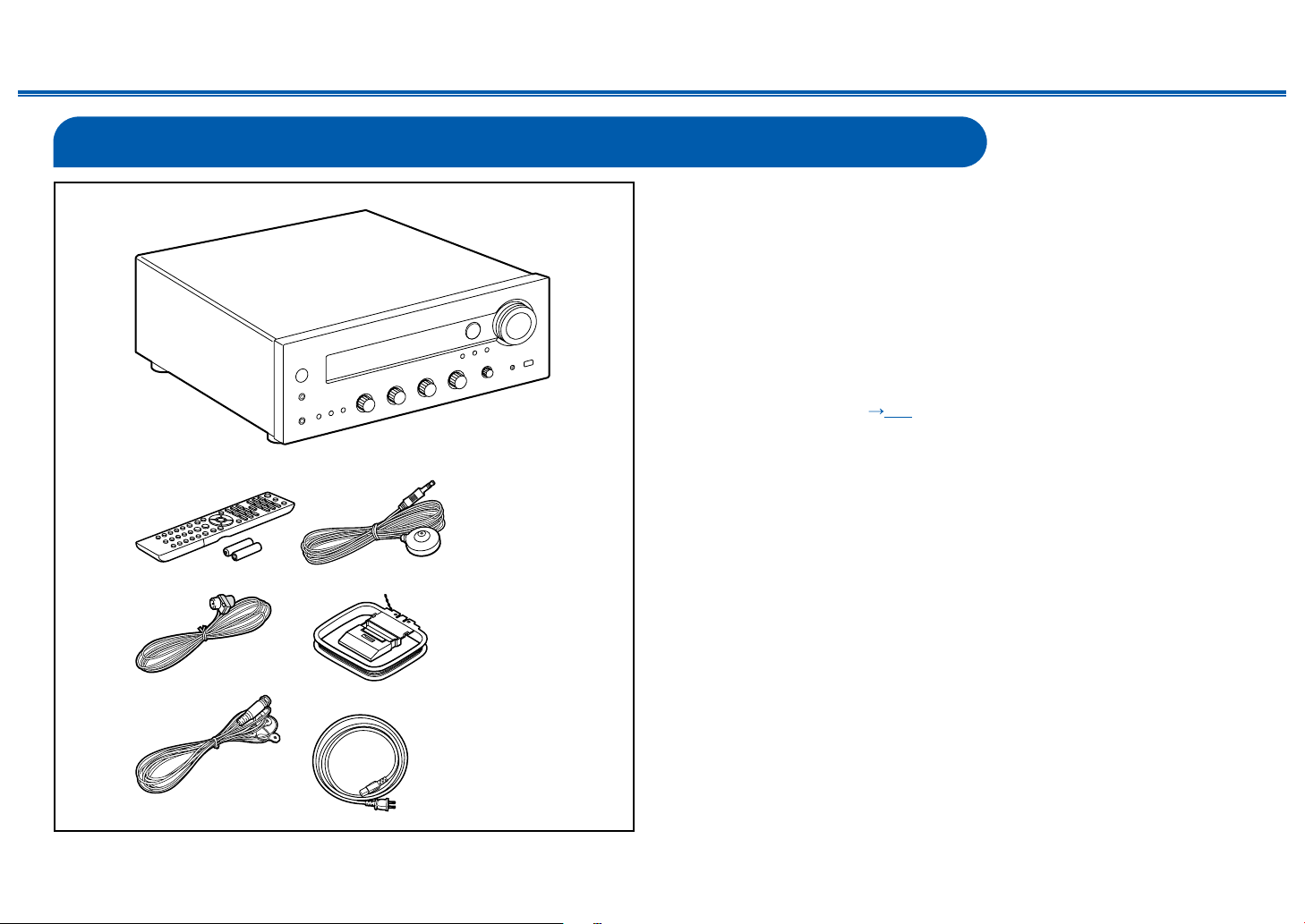
What’s in the box
Contents ≫ Connections ≫ Playback ≫ Setup
1. Main unit (1)
2. Remote controller (RC-975S) (1), Batteries (AAA/R03) (2)
3. Speaker setup microphone (1)
• Used during Initial Setup.
4. Indoor FM antenna (For North American models only) (1)
5. AM loop antenna (For North American models only) (1)
6. DAB/FM antenna (For European models only) (1)
7. Power cord (1)
• Quick Start Guide (1)
* This is an online user manual. This is not supplied with the product.
• Connect speakers with an impedance of 4 Ω to 16 Ω. When using the 2.1
Channel System (A+B) (
and B, connect speakers with 8 Ω to 16 Ω impedance.
• The power cord must be connected only after all other connections are
completed.
• We will not accept any responsibility for damage arising from the connection
with equipment manufactured by other companies.
• Network services and content that can be used may no longer be available
if new functions are added by updating rmware or the service providers
terminate their services. Also, available services may differ depending on your
area.
• Details on the rmware update will be posted on our website and through
other means at a later date.
• The illustrations in this manual use those of North American models unless
otherwise mentioned.
• Specications and appearance are subject to change without prior notice.
p22) for simultaneous output from SPEAKER A
≫
5
Front Panel≫ Rear Panel≫ Remote≫

Contents ≫ Connections ≫ Playback ≫ Setup
Additional Function (Firmware Update)
This unit is equipped with a function to update the rmware via network or USB port when the rmware update is announced after purchase. This enables various
functions to be added and operations to be improved.
Depending on the manufacturing timing of the product, the rmware may be switched to the updated one. In such a case, new functions may be added from the start.
For how to conrm the latest rmware contents and the rmware version of your product, see the following section.
Update Information of the rmware
For the latest rmware contents and the rmware version, visit our company's website. If the rmware version of your product differs from the latest one, it is
recommended to update the rmware.
To conrm the rmware version of your product, press the SETUP button on the remote controller, and refer to "7. Miscellaneous" - "Firmware Update" - "Version" (
p96).
Operation of added new functions
If functions are added or changed from contents described in the Instruction Manual, see the following reference.
Supplementary Information ≫
≫
Firmware Update Procedure ( p7)
6
Front Panel≫ Rear Panel≫ Remote≫

Firmware Update Procedure
Contents ≫ Connections ≫ Playback ≫ Setup
≫
The update may take approx. 20 minutes to complete via network or via USB
port. Existing settings are guaranteed in either updating method.
When this unit is connected to the network, notications of rmware updates
may be displayed. To update the rmware, select "Update Now" with the cursor
buttons of the remote controller and press ENTER. The unit automatically enters
standby mode after "Completed!" is displayed, and the update is completed.
Disclaimer: The program and accompanying online documentation are furnished
to you for use at your own risk.
Our company will not be liable and you will have no remedy for damages for
any claim of any kind whatsoever concerning your use of the program or the
accompanying online documentation, regardless of legal theory, and whether
arising in tort or contract.
In no event will our company be liable to you or any third party for any special,
indirect, incidental, or consequential damages of any kind, including, but not
limited to, compensation, reimbursement or damages on account of the loss of
present or prospective prots, loss of data, or for any other reason whatsoever.
Updating the Firmware via Network
• While updating the rmware, do not do the following:
– Disconnecting and reconnecting cables, USB storage device, speaker
setup microphone or headphones, or performing operations on the unit
such as turning the power off
– Accessing this unit from a PC or smartphone using their applications
• Check that the unit is turned on, and the connection to the Internet is secured.
• Turn off control devices (PC etc.) connected to the network.
• Stop an Internet radio, USB storage device, or server content being played.
• If the multi-zone function is active, turn it off.
• If "HDMI CEC" is set to "On", set it to "Off".
– Press SETUP. Next, select "5. Hardware" - "HDMI" and press ENTER, then
select "HDMI CEC" and select "Off".
* The descriptions may differ from the actual on-screen displays, however, operations
and functions are the same.
Update
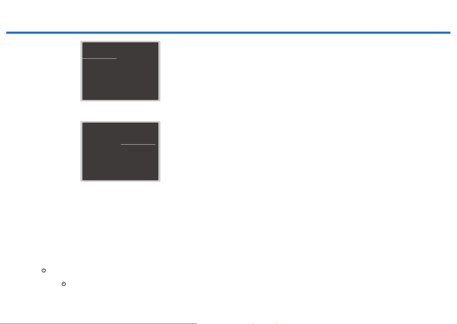
1. Press SETUP.
The Setup menu is displayed on the TV screen.
Setup
1. Input/Output Assign
2. Speaker
3. Audio Adjust
4. Source
5. Hardware
6. Multi Zone
7. Miscellaneous
1. TV Out / OSD
2. HDMI Input
3. Digital Audio Input
4. Analog Audio Input
My Input Information
5.
2. Select "7. Miscellaneous" - "Firmware Update" - "Update via NET" with the
cursors in order, then press ENTER.
Setup
1. Input/Output Assign
2. Speaker
3. Audio Adjust
4. Source
5. Hardware
6. Multi Zone
7. Miscellaneous
1. Tuner
2. Firmware Update
3. Initial Setup
4. Lock
5. Factory Reset
• If "Firmware Update" is grayed out and cannot be selected, wait for a while
until it starts up.
• If there is no updatable rmware, "Update via NET" cannot be selected.
3. Press ENTER with "Update" selected, and start update.
• During the update, the TV screen may go black depending on the program
to be updated. In such a case, check the progress on the display of the
unit. The TV screen will remain black until the update is completed and the
power is turned on again.
• When "Completed!" is displayed, the update is complete.
7
Front Panel≫ Rear Panel≫ Remote≫

Contents ≫ Connections ≫ Playback ≫ Setup
≫
4. Press ON/STANDBY on the main unit to turn the unit into standby mode.
The process is completed, and your rmware is updated to the latest version.
• Do not use on the remote controller.
If an Error Message is Displayed
If an error occurs, "- Error!" is displayed on the display of the unit. (""
represents an alphanumeric character.) Refer to the following descriptions and
check.
Error Code
• -01, -10:
LAN cable not found. Connect the LAN cable properly.
• -02, -03, -04, -05, -06, -11, -13, -14, -16, -17, -18, -20,
-21:
Internet connection error. Check the following:
– Whether the router is turned on
– Whether this unit and the router are connected via the network
Unplug and plug the power cords of this unit and the router. This may solve
the problem. If you are still unable to connect to the Internet, the DNS server
or proxy server may be temporarily down. Check the server operation status
with your Internet service provider.
• Others:
After removing the power plug once, insert it to the outlet, and then start the
operation from the beginning.
Updating via USB
• While updating the rmware, do not do the following:
– Disconnecting and reconnecting cables, USB storage device, speaker
setup microphone or headphones, or performing operations on the unit
such as turning the power off
– Accessing this unit from a PC or smartphone using their applications
• Prepare a 256 MB or larger USB storage device. The format of USB storage
devices supports FAT16 or FAT32 le system format.
– Media inserted into a USB card reader may not be used for this function.
– USB storage devices equipped with the security function are not supported.
– USB hubs and USB devices equipped with the hub function are not
supported. Do not connect these devices to the unit.
• Delete any data stored on the USB storage device.
• Turn off control devices (PC etc.) connected to the network.
• Stop an Internet radio, USB storage device, or server content being played.
• If the multi-zone function is active, turn it off.
• If "HDMI CEC" is set to "On", set it to "Off".
– Press SETUP. Next, select "5. Hardware" - "HDMI" and press ENTER, then
select "HDMI CEC" and select "Off".
* Depending on the USB storage device or its content, long time may be required
for loading, the content may not be loaded correctly, or power may not be supplied
correctly.
* Our company will not be liable whatsoever for any loss or damage of data, or storage
failure arising from the use of the USB storage device. Please note this in advance.
* The descriptions may differ from the actual on-screen displays, however, operations
and functions are the same.
Update
1. Connect the USB storage device to your PC.
2. Download the rmware le from the our company's website to your PC and
unzip.
Firmware les are named as below.
ONKAVR_R.zip
Unzip the le on your PC. The number of unzipped les and folders varies
depending on the model.
3. Copy all unzipped les and folders to the root folder of the USB storage
device.
• Make sure to copy the unzipped les.
4. Connect the USB storage device to the USB port of this unit.
• If an AC adapter is supplied with the USB storage device, connect the AC
adapter, and use it with a household outlet.
• If the USB storage device has been partitioned, each section will be treated
as an independent device.
5. Press SETUP.
The Setup menu is displayed on the TV screen.
8
Front Panel≫ Rear Panel≫ Remote≫
Contents ≫ Connections ≫ Playback ≫ Setup
≫
Setup
1. Input/Output Assign
2. Speaker
3. Audio Adjust
4. Source
5. Hardware
6. Multi Zone
7. Miscellaneous
1. TV Out / OSD
2. HDMI Input
3. Digital Audio Input
4. Analog Audio Input
My Input Information
5.
6. Select "7. Miscellaneous" - "Firmware Update" - "Update via USB" with the
cursors in order, then press ENTER.
Setup
1. Input/Output Assign
2. Speaker
3. Audio Adjust
4. Source
5. Hardware
6. Multi Zone
7. Miscellaneous
1. Tuner
2. Firmware Update
3. Initial Setup
4. Lock
5. Factory Reset
• If "Firmware Update" is grayed out and cannot be selected, wait for a while
until it starts up.
• If there is no updatable rmware, "Update via USB" cannot be selected.
7. Press ENTER with "Update" selected, and start update.
• During the update, the TV screen may go black depending on the program
to be updated. In such a case, check the progress on the display of the
unit. The TV screen will remain black until the update is completed and the
power is turned on again.
• During the update, do not turn the power off, or disconnect or reconnect the
USB storage device.
• When "Completed!" is displayed, the update is complete.
8. Disconnect the USB storage device from the unit.
9. Press
ON/STANDBY on the main unit to turn the unit into standby mode.
The process is completed, and your rmware is updated to the latest version.
• Do not use
on the remote controller.
If an Error Message is Displayed
If an error occurs, "- Error!" is displayed on the display of the unit. (""
represents an alphanumeric character.) Refer to the following descriptions and
check.
Error Code
• -01, -10:
The USB storage device cannot be recognized. Check if the USB storage
device or USB cable is securely inserted to the USB port of the unit.
Connect the USB storage device to an external power source if it has its own
power supply.
• -05, -13, -20, -21:
The rmware le is not present in the root folder of the USB storage device, or
the rmware le is for another model. Retry from the download of the rmware
le.
• Others:
After removing the power plug once, insert it to the outlet, and then start the
operation from the beginning.
9
Front Panel≫ Rear Panel≫ Remote≫
Part Names
Front Panel
Contents ≫ Connections ≫ Playback ≫ Setup
≫
For details, see ( p11)
10
Front Panel≫ Rear Panel≫ Remote≫

Contents ≫ Connections ≫ Playback ≫ Setup
≫
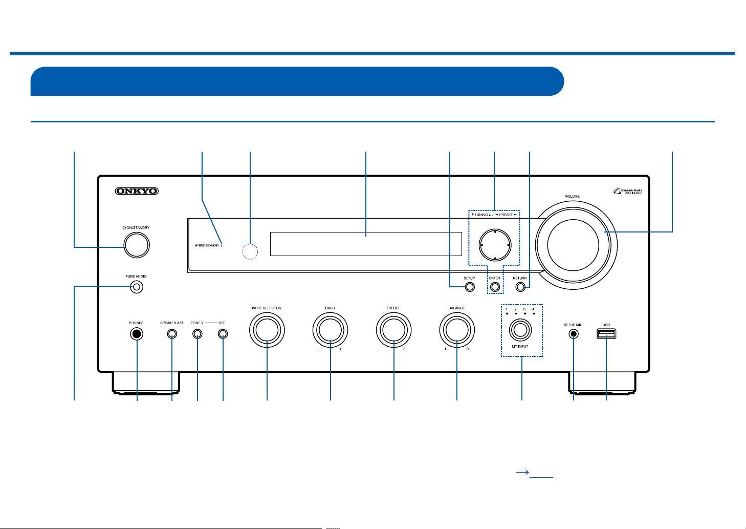
1. ON/STANDBY button
2. HYBRID STANDBY indicator: Lights up when any of the following functions is
working or enabled in standby state of this unit. When this indicator is lighting,
the power consumption in standby state increases, however, the increase in
power consumption is minimized by entering the HYBRID STANDBY mode
where only the essential circuits operate.
– HDMI CEC ( p89)
– HDMI Standby Through ( p89)
– USB Power Out at Standby ( p93)
– Network Standby ( p94)
– Bluetooth Wakeup ( p94)
3. Remote control sensor: Receives signals from the remote controller.
• The reception range of the remote controller is within a distance of approx.
16´/5 m, and an angle of 20° in vertical direction and 30° to right and left.
4. Display ( p12)
5. SETUP button: You can display advanced setting items on the TV and the
display to have a more enjoyable experience with this unit. ( p78)
6. Cursor buttons ( / / / ) and ENTER button: Select an item with the
cursors, and press ENTER to conrm your selection. When using TUNER, use
them to tune in to stations. ( p61)
7. RETURN button: Returns the display to the previous state while setting.
8. VOLUME
9. PURE AUDIO button/indicator: Used to switch to the Pure Audio listening
mode. The LED lights when it is on, the display turns off, and the "Bass" and
"Treble" settings are disabled.
• Pure Audio mode cannot be selected when using the Multi-zone feature.
Activating the Multi-zone feature while this mode is selected automatically
switches the listening mode to Direct.
10.
PHONES jack: Connect headphones with a standard plug (ø1/4″/6.3 mm).
11.
SPEAKER A/B button : Select whether to output audio from SPEAKER A,
SPEAKER B or both.
12.
ZONE 2 button: Controls the multi-zone function. ( p69)
13.
OFF button: Switches the multi-zone function off. ( p69)
14.
INPUT SELECTOR dial: Switches the input to be played.
15.
BASS dial: Adjusts the bass.
16.
TREBLE dial: Adjusts the treble.
17.
BALANCE dial: Adjusts the balance of the sounds output from the left and right
speakers.
18.
MY INPUT dial/indicators: You can register settings conditions such as the
current input selection or listening mode, and then recall them. The indicator
corresponding to the selected MY INPUT number lights. ( p73)
19.
SETUP MIC jack: Connect the supplied speaker setup microphone. ( p101)
20.
USB jack: A USB storage device is connected so that music les stored in it
can be played. You can also supply power (5 V/0.5 A) to USB devices with a
USB cable.
11
Front Panel≫ Rear Panel≫ Remote≫

Display
Contents ≫ Connections ≫ Playback ≫ Setup
≫
1. Speaker/Channel display: The currently selected speaker system lights.
2. Lights in the following conditions.
: Headphones are connected.
Z2: ZONE 2 is on.
: Connected by BLUETOOTH.
: Connected by Wi-Fi.
NET: Lights when connected to the network with the "NET" input selector. It
will blink if incorrectly connected to the network.
USB: Lights when the "NET" input selector is selected, a USB device is
connected and the USB input is selected. It will blink if the USB device is not
properly connected.
HDMI: HDMI signals are input and the HDMI input is selected.
DIGITAL: Digital signals are input and the digital input is selected.
A: Audio is output only to SPEAKER A.
B: Audio is output only to SPEAKER B.
AB: Audio is output to both SPEAKER A and SPEAKER B.
3. Lights according to the type of input digital audio signals.
4. Lights in the following conditions.
RDS (European models): Receiving RDS broadcasting.
TUNED: Receiving DAB (European models)/AM (North American models)/FM
radio
FM ST: Receiving FM stereo.
SLEEP: Sleep timer is set. ( p93)
AUTO STBY: Auto Standby is set. ( p93)
5. Blinks when muting is on.
6. Displays various information of the input signals.
7. Cursors ( / / / ): These may light when performing operations while
“NET” is selected with the input selector. / light when there are multiple
folders or les that are available to be selected. / light when text
information does not t with the range provided by “6”.
12
Front Panel≫ Rear Panel≫ Remote≫
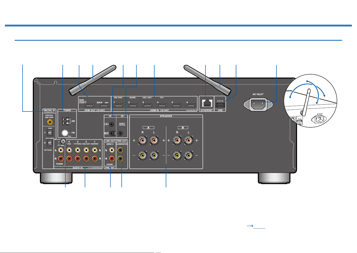
Rear Panel
(North American models)
Contents ≫ Connections ≫ Playback ≫ Setup
≫
90°
180°
For details, see ( p15)
13
Front Panel≫ Rear Panel≫ Remote≫
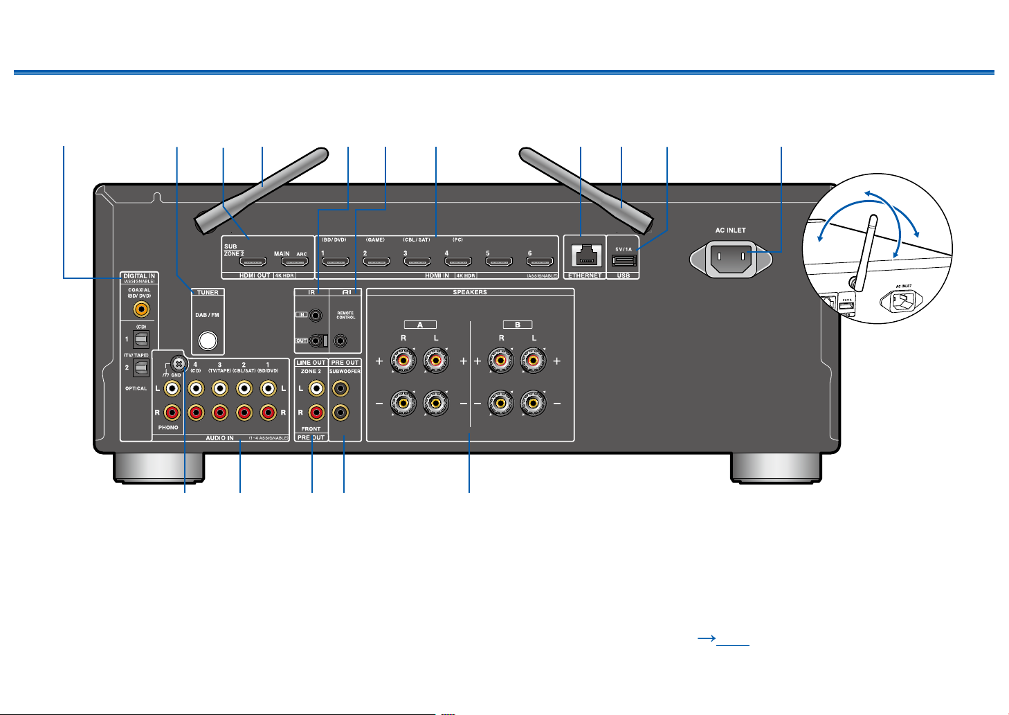
(European models)
Contents ≫ Connections ≫ Playback ≫ Setup
≫
90°
180°
For details, see ( p15)
14
Front Panel≫ Rear Panel≫ Remote≫

Contents ≫ Connections ≫ Playback ≫ Setup
1. DIGITAL IN OPTICAL/COAXIAL jacks: Input TV or AV component digital audio
signals with a digital optical cable or digital coaxial cable.
2. TUNER AM/FM terminal (North American models): Connect the supplied
antennas.
TUNER DAB/FM terminal (European models): The supplied antenna is
connected.
3. HDMI OUT jacks: Transmit video signals and audio signals with an HDMI
cable connected to a monitor such as a TV or projector.
4. Wireless antenna: Used for Wi-Fi connection or when using a BLUETOOTH
enabled device. Adjust the angles according to the connection status.
5. IR IN/OUT terminals: Connect a remote control receiver unit. ( p34)
6. REMOTE CONTROL jack: An Onkyo product with RI ("Remote Interactive")
jack can be connected and synchronized with this unit. ( p29)
7. HDMI IN jacks: Transmit video signals and audio signals with an HDMI cable
connected to an AV component.
8. ETHERNET port: Connect to the network with a LAN cable.
9. USB port: Connect a USB storage device to play music les. ( p47) You
can also supply power (5 V/1 A) to USB devices with a USB cable.
10.
AC INLET: Connect the supplied power cord.
11.
GND terminal: Connect the ground wire of the turntable.
12.
AUDIO IN jacks: Input AV component audio signals with an analog audio
cable.
13.
ZONE 2 LINE OUT jacks: Output audio signals with an analog audio cable
connected to a pre-main amplier in a separate room (ZONE 2).
PRE OUT FRONT jacks: Connect to a power amplier. ( p24)
14.
SUBWOOFER PRE OUT jacks: Connect a powered subwoofer with a
subwoofer cable. Up to two powered subwoofers can be connected. The same
signal is output from each SUBWOOFER PRE OUT jack.
15.
SPEAKERS terminals: Connect speakers with speaker cables. (North
American models support banana plugs. Use a plug 4 mm in diameter. Y plug
connection is not supported.)
≫
15
Front Panel≫ Rear Panel≫ Remote≫
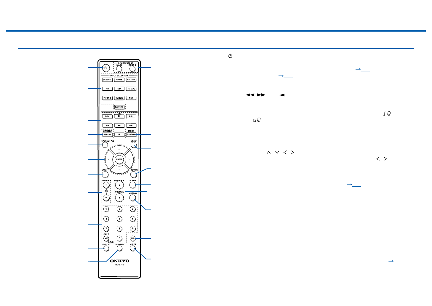
Remote Controller
Contents ≫ Connections ≫ Playback ≫ Setup
1. ON/STANDBY button
2. INPUT SELECTOR buttons: Switches the input to be played.
3. Play buttons: Used to control play of a Music Server ( p50) or device
connected via USB ( p47), or of RI connected devices. Also, switching to
"CEC MODE" with "13. MODE button" allows you to operate an HDMI CEC
function-enabled AV component. (Some devices may not be operated.)
• The , , and buttons can only be used when playing RI connected
devices.
4. REPEAT button: Used for repeat play operations when playing Music Server
or USB. Each time you press the button, the mode switches from (1-track
repeat) to (folder repeat).
MEMORY button: Used to register DAB (European models)/AM (North
American models)/FM radio stations.
5. SPEAKER A/B button: Select whether to output audio from SPEAKER A,
SPEAKER B or both.
6. Cursor buttons ( / / / ) and ENTER button: Select an item with the
cursors, and press ENTER to conrm your selection. Pressing / button
allows you to switch the screen when a music folder list or le list is not
displayed on one screen on the TV.
7. SETUP button: Displays advanced setting items on the TV or the display to
have a more enjoyable experience with this unit. ( p78)
8. CH (+/-) buttons: Used to select DAB (European models)/AM (North American
models)/FM radio stations.
9. Numbered buttons
10.
DISPLAY button: Switches the information on the display. You can display
information such as the input source and input format when pressed
repeatedly during play.
When receiving stations transmitting RDS, it displays text information.
(European models)
11.
DIMMER button: Switches the brightness of the display with three levels. It
cannot be turned off completely.
12.
REMOTE MODE MAIN/ZONE 2 buttons: Switch the remote controller
operation mode to the main room or the separate room (ZONE 2). ( p69)
13.
RANDOM button: Used for random play operations when playing Music Server
≫
16
Front Panel≫ Rear Panel≫ Remote≫

Contents ≫ Connections ≫ Playback ≫ Setup
or USB. (random) turns on or off each time you press the button.
MODE button (North American models): Switches between automatic tuning
and manual tuning for AM/FM stations ( p61).
MODE button (European models): Switches tuning to an FM station between
automatic tuning and manual tuning ( p61), and allows you to select the
order for displaying DAB stations ( p65).
Also, when an HDMI CEC function-enabled AV component is connected to
this unit, you can switch "3. Play buttons" between "CEC MODE" and "RCV
MODE" (normal mode).
14.
MENU button: Used to display the internet radio service menus.
15.
RETURN button: Returns the display to the previous state while setting.
16.
AUDIO button: Pressing this button during playback allows you to make
settings such as "HDMI" and "Level" quickly on the TV screen while playing. (
p97)
17.
VOLUME buttons
18.
MUTING button: Temporarily mutes audio. Press the button again to cancel
muting.
19.
CLR button: Deletes all characters you have entered when entering text on the
TV screen.
20.
SLEEP button: Sets the sleep timer. Select the time from "30 min", "60 min"
and "90 min". ( p75)
When the remote controller isn't working: The remote
controller may have switched to the mode for controlling ZONE
2. Press REMOTE MODE MAIN to switch to the mode to control
the main room.
≫
17
Front Panel≫ Rear Panel≫ Remote≫
Front Panel≫ Rear Panel≫ Remote≫
Contents ≫ Connections ≫ Playback ≫ Setup
Connections
Connecting speakers 19
Connecting the TV 25
Connecting Playback Devices 28
Connecting an AV Component in a Separate Room
(Multi-zone Connection) 30
Connecting Antennas 32
Network Connection 33
Connecting External Control Devices 34
Connecting the Power Cord 35
≫
18
Front Panel≫ Rear Panel≫ Remote≫
Contents ≫ Connections ≫ Playback ≫ Setup
1/2˝
(12 mm)
Connecting speakers
Speaker Connections and "Speaker Setup" Settings
Connections
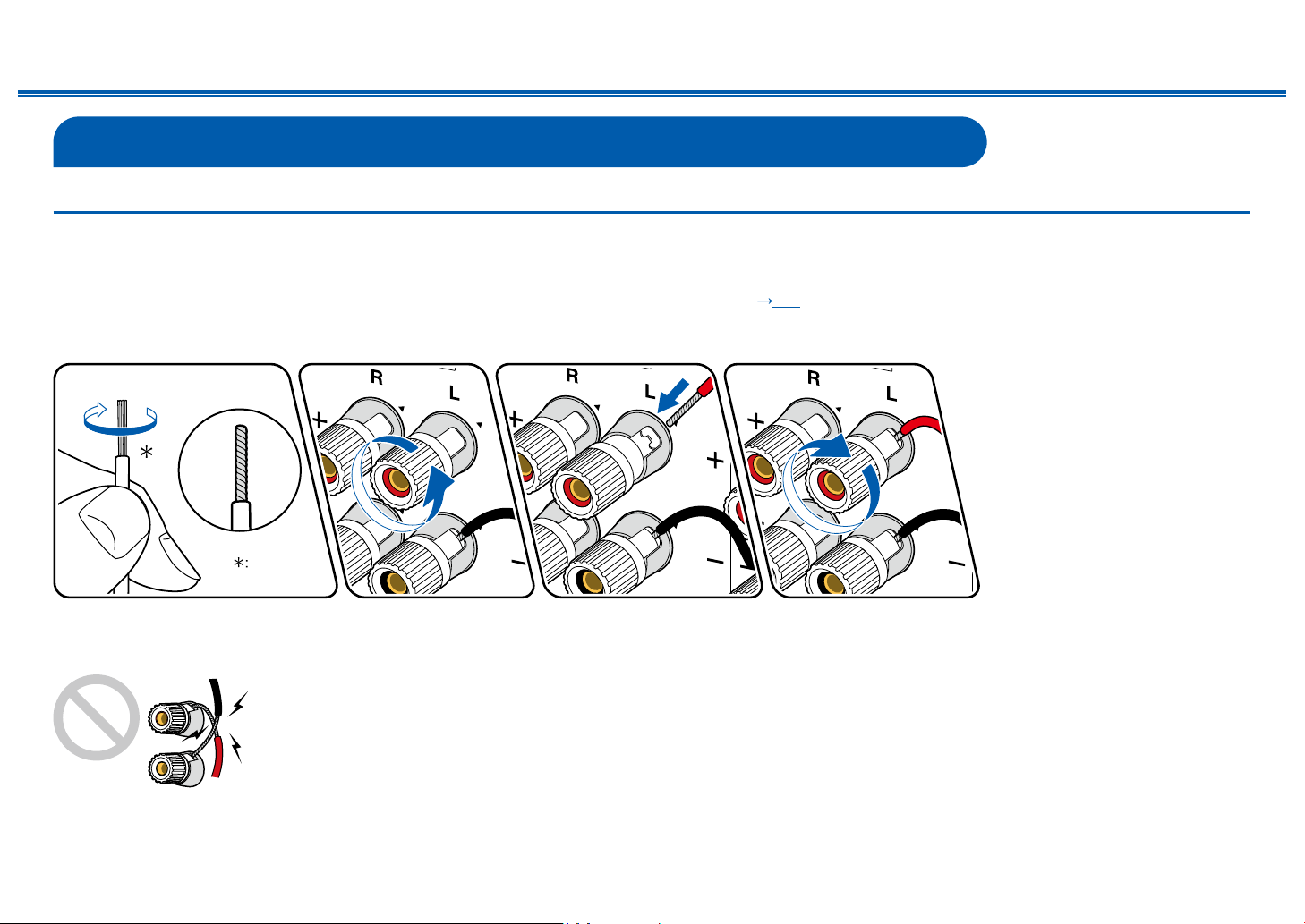
(Note) Speaker Impedance
Connect speakers with an impedance of 4 Ω to 16 Ω. When using the 2.1 Channel System (A+B) ( p22) for simultaneous output from SPEAKER A and B, connect
speakers with 8 Ω to 16 Ω impedance.
Connect the Speaker Cables
≫
Make correct connection between the unit's jacks and speaker's jacks (+ side to + side, and - side to - side) for each channel. If the connection is wrong, a bass sound
will not be reproduced properly due to reverse phase. Twist the wires exposed from the tip of the speaker cable so that the wires do not stick out of the speaker terminal
when connecting. If the exposed wires touch the rear panel, or the + side and – side wires touch each other, a malfunction may occur.
19
Front Panel≫ Rear Panel≫ Remote≫
Contents ≫ Connections ≫ Playback ≫ Setup
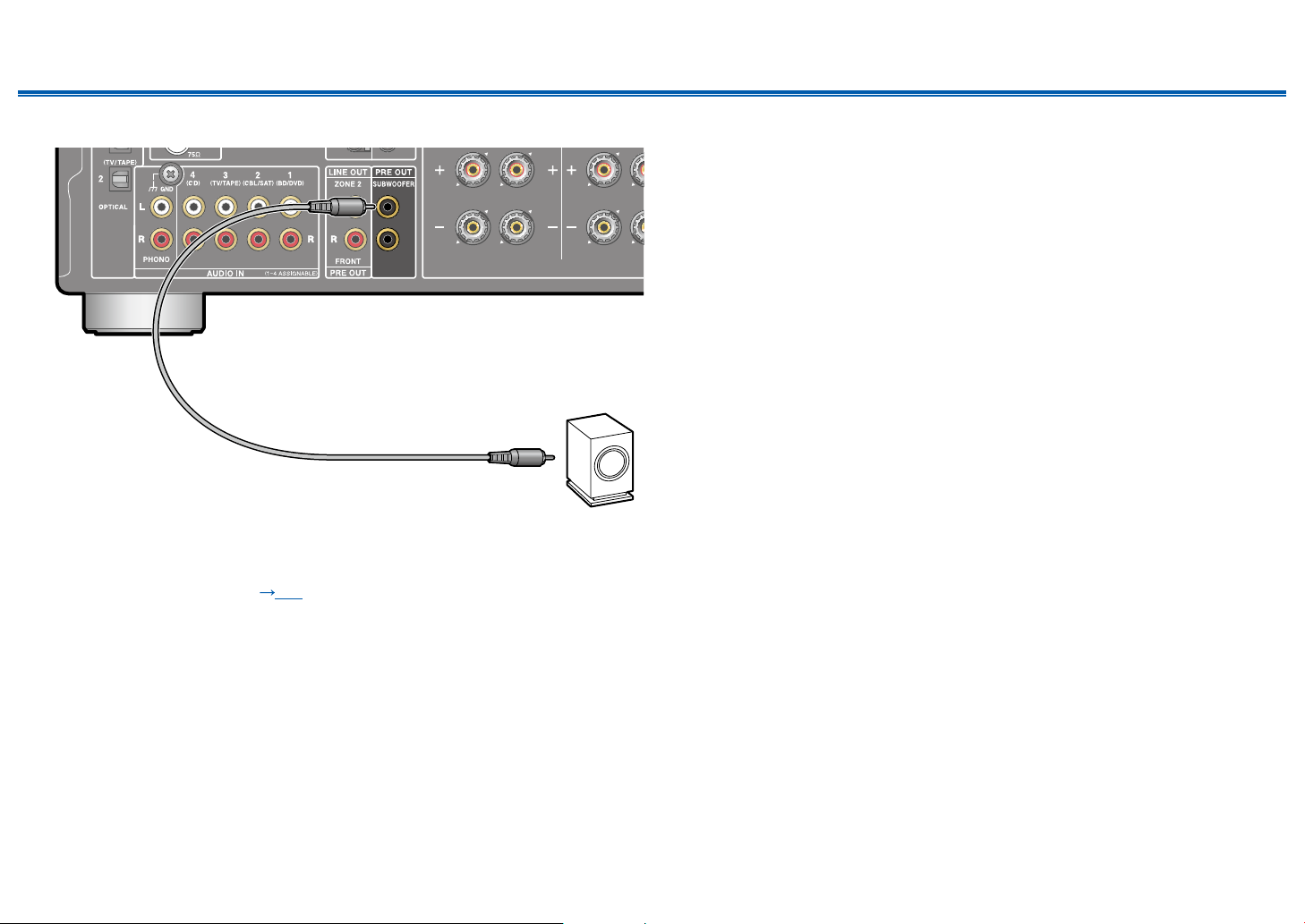
Connect the Subwoofer
a
a Subwoofer cable
Connect a powered subwoofer with this unit using a subwoofer cable. Up to two
powered subwoofers can be connected. The same signal is output from each
SUBWOOFER PRE OUT jack.
• When only SPEAKER B (
output from the powered subwoofer.
p22) is outputting audio, there will be no audio
≫
20
Front Panel≫ Rear Panel≫ Remote≫
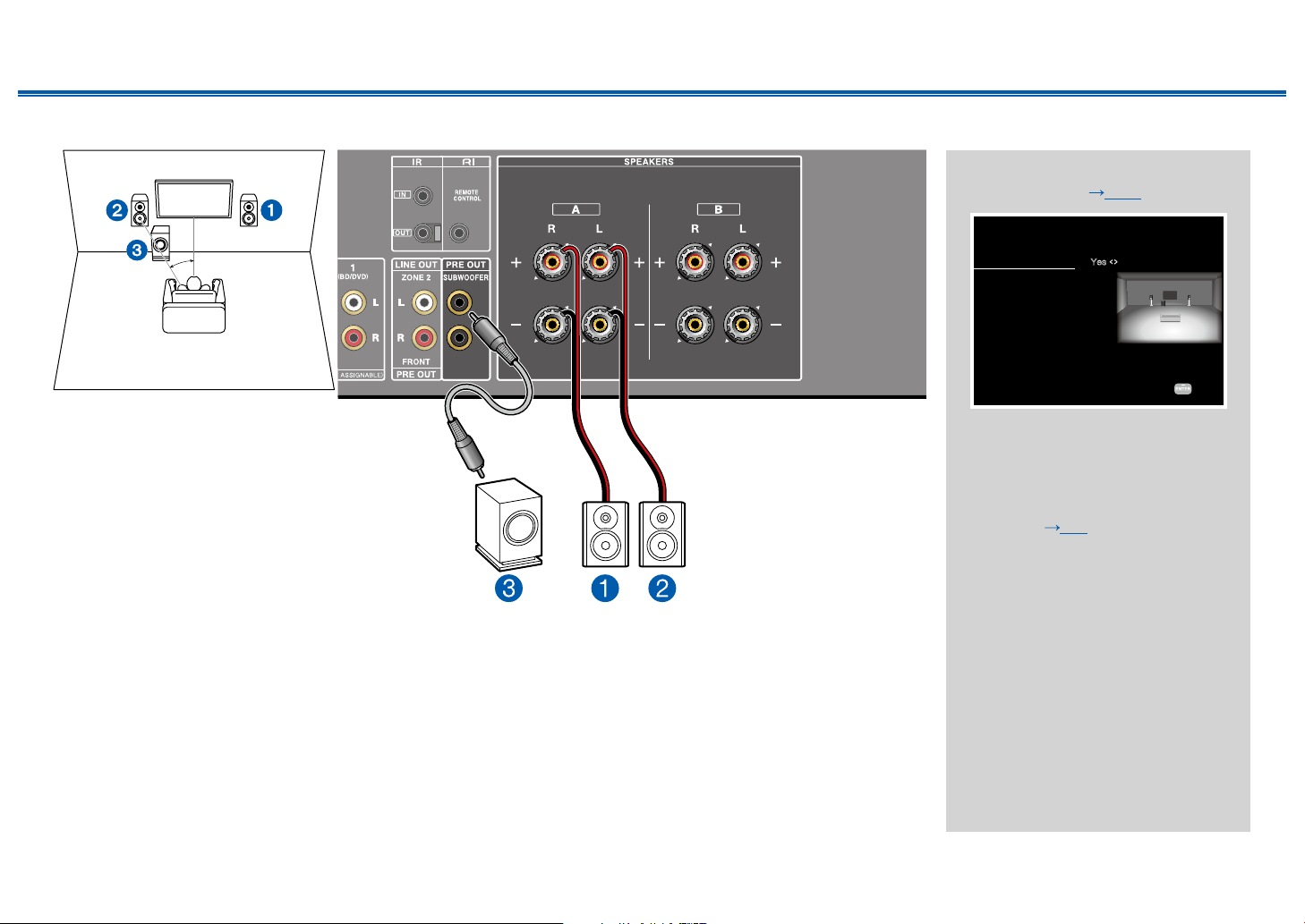
2.1 Channel System (SPEAKERS A)
Speaker Setup
Specifies whether the powered subwoofer is connected or not.
Next
< >
Contents ≫ Connections ≫ Playback ≫ Setup
"Speaker Setup" settings during
Initial Setup ( p101)
≫
a
a: 22° to 30°
1,2 Front Speakers
3 Powered Subwoofer
Front speakers output front stereo sound. The powered subwoofer reproduces bass sounds and enriches the sound eld.
The optimal positioning for front speakers is ear height. Placing the powered subwoofer between the front of the listening
position and a front speaker gives you a natural sound even when playing music.
Subwoofer
Speaker B
Zone 2 Lineout
Speaker Impedance
Yes
A / B
Zone 2
6ohms or above
• Subwoofer: Yes
(Select "No" when not using a
Subwoofer)
• Speaker B: A/B
• Zone 2 Lineout/(Preout): Any
value ( p85)
• Speaker Impedance:
4 ohms: When any of the
connected speakers have 4
Ω or more to less than 6 Ω
impedance.
6 ohms or above: When the
connected speakers all have 6
Ω or more impedance.
21
Front Panel≫ Rear Panel≫ Remote≫

2.1 Channel System (SPEAKERS A+B)
**
Speaker Setup
Specifies whether the powered subwoofer is connected or not.
Next
< >
Contents ≫ Connections ≫ Playback ≫ Setup
"Speaker Setup" settings during
Initial Setup ( p101)
≫
a
a: 22° to 30°
1,2 Front Speakers
3 Powered Subwoofer
*: Speakers B
Speakers B
Along with the 2.1 Channel System (SPEAKERS A) ( p21), you can connect one more set of front speakers to use as
a Speaker B System.
When outputting audio simultaneously from 2 speaker systems
Connect speakers with an impedance of 8 Ω to 16 Ω.
When switching to either A or B for audio output
Connect speakers with an impedance of 4 Ω to 16 Ω.
• Press SPEAKER A/B on the remote controller or the main unit to switch the audio output. The selection changes in the
order SPEAKER A, SPEAKER B, SPEAKER A+B with each press.
• When only SPEAKER B is outputting audio, there will be no audio output from the powered subwoofer.
Subwoofer
Speaker B
Zone 2 Lineout
Speaker Impedance
Yes
A / B
Zone 2
6ohms or above
• Subwoofer: Yes
(Select "No" when not using a
Subwoofer)
• Speaker B: A/B
• Zone 2 Lineout/(Preout): Any
value ( p85)
• Speaker Impedance:
4 ohms: When switching A/B
for audio output, at least one
of the connected speakers
have 4 Ω or more to less than
6 Ω impedance. Also when
outputting audio simultaneously
from 2 speaker systems.
6 ohms or above: When
switching A/B for audio output,
the connected speakers all have
6 Ω or more impedance.
22
Front Panel≫ Rear Panel≫ Remote≫

Contents ≫ Connections ≫ Playback ≫ Setup
Speaker Setup
Specifies whether the powered subwoofer is connected or not.
Next
< >
2.1 Channel System (Bi-wiring the Speakers)
≫
"Speaker Setup" settings during
Initial Setup ( p101)
a
a: 22° to 30°
1,2 Front Speakers
3 Powered Subwoofer
For high-
frequency
For low-
frequency
You can connect speakers that support bi-wiring to this unit. Connect the treble and bass correctly. Be sure to remove
the jumper bar connecting between the woofer jacks and tweeter jacks of the Bi-wiring supported speakers. Refer to the
instruction manual of your speakers as well.
• As shown on the illustration, the wiring terminals of SPEAKERS B are connected to the tweeter and SPEAKERS A are
connected to the woofer. However, wiring them the other way around is also possible.
Subwoofer
Speaker B
Zone 2 Lineout
Speaker Impedance
Yes
Bi-Wiring
Zone 2
6ohms or above
• Subwoofer: Yes
(Select "No" when not using a
Subwoofer)
• Speaker B: Bi-Wiring
• Zone 2 Lineout/(Preout): Any
value ( p85)
• Speaker Impedance:
4 ohms: When any of the
connected speakers have 4
Ω or more to less than 6 Ω
impedance.
6 ohms or above: When the
connected speakers all have 6
Ω or more impedance.
23
Front Panel≫ Rear Panel≫ Remote≫
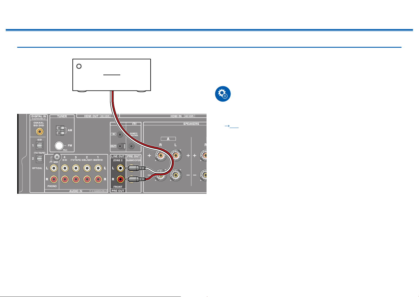
Connecting a Power Amplier
Contents ≫ Connections ≫ Playback ≫ Setup
≫
Power amplier
a
You can connect a power amplier to the unit and use the unit as a pre-amplier
in order to produce a large volume that cannot be output with the unit only.
Connect the front speakers to the power amplier. For details, refer to the power
amplier's instruction manual.
• Use the PRE OUT FRONT jacks for connection as show on the left.
Setup
• Settings are required to output audio to the power amplier. Press SETUP on
the remote controller, and set "2. Speaker" - "Conguration" - "Zone 2 Lineout"
( p85) to "Front".
a Analog audio cable
24
Front Panel≫ Rear Panel≫ Remote≫
Contents ≫ Connections ≫ Playback ≫ Setup
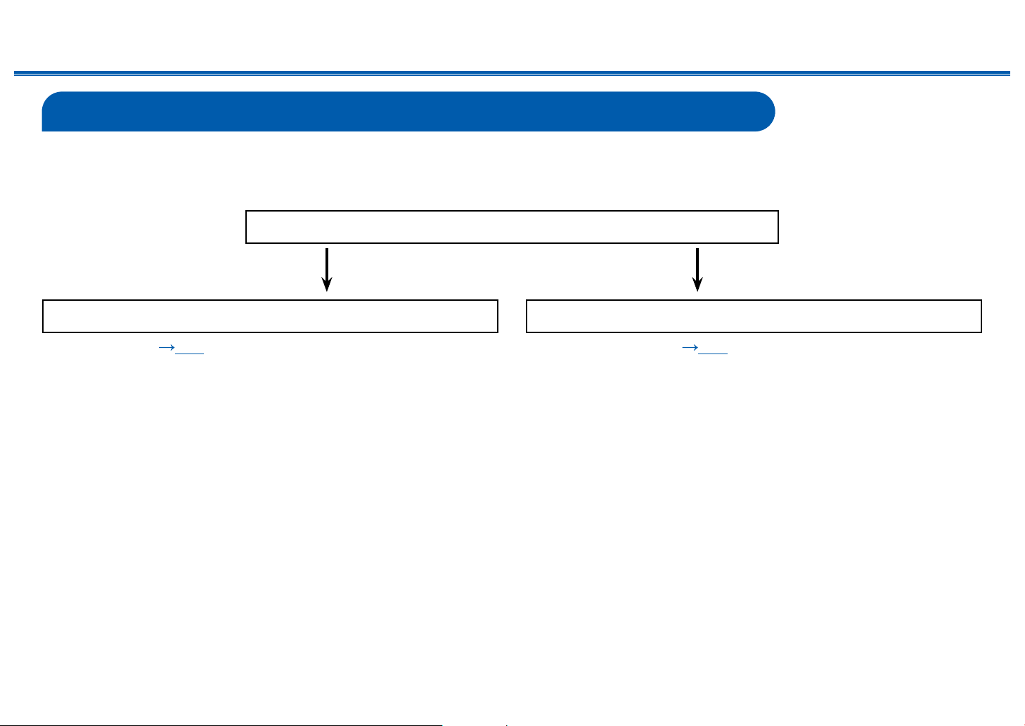
Connecting the TV
Connect this unit between a TV and AV component. Connecting this unit with the TV can output the video and audio signals of the AV component to the TV, or play the
audio of the TV on this unit. Connection with the TV differs depending on whether the TV supports the ARC (Audio Return Channel) function or not. The ARC function
transmits the audio signals of the TV via an HDMI cable, and plays the audio of the TV on this unit. To check if the TV supports the ARC function, refer to the instruction
manual of the TV, etc.
Does your TV support the ARC function?
Yes No
• To ARC TV ( p26) • To Non-ARC TV ( p27)
≫
25
Front Panel≫ Rear Panel≫ Remote≫
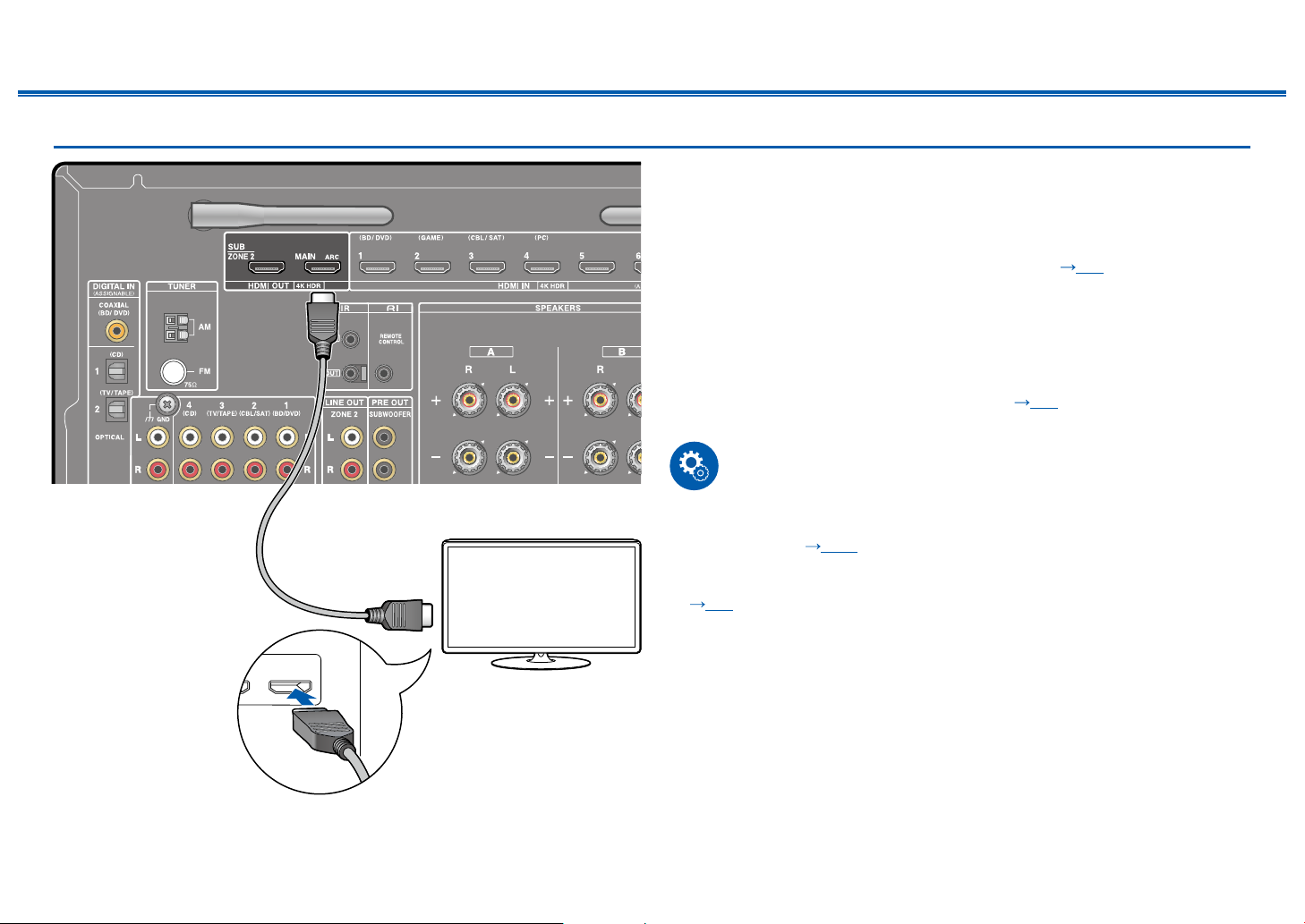
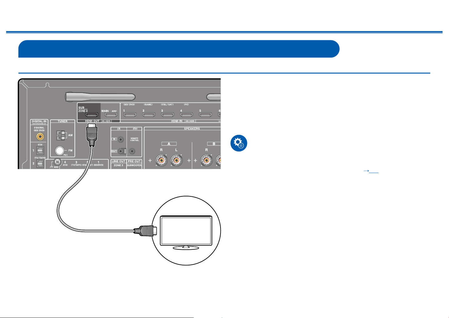
To ARC TV
IN(ARC)
Contents ≫ Connections ≫ Playback ≫ Setup
If the TV supports the ARC (Audio Return Channel) function (*), use only the
HDMI cable to connect with the TV. Use the ARC-compatible HDMI IN jack of the
TV for connection. You connect the HDMI cable to the HDMI OUT jack labeled
"ARC"on the receiver side.
• Another TV or projector can be connected to the HDMI OUT SUB jack. Switch
between MAIN and SUB using the "AUDIO Menu" ( p97). Note that this
jack is not ARC-compatible.
• If devices with different resolutions are connected to HDMI OUT MAIN jack
and SUB jack, images are output with the lower resolution.
• If a 4K high-quality video is played, use a Premium High Speed HDMI Cable
or Premium High Speed HDMI Cable with Ethernet whose package has a
"PREMIUM Certied Cable" label. Furthermore, in "Switching the HDMI 4K
Signal Format Input and Output by this Unit" ( p77), change the setting
value to "Enhanced".
Setup
• Settings are required to use the ARC function. Select "Yes" for "3. ARC Setup"
a
TV
in Initial Setup (
the Setup menu after Initial Setup is completed. Press SETUP on the remote
controller, and set "5. Hardware" - "HDMI" - "Audio Return Channel" to "On". (
p90)
• For detailed settings for TV connection, CEC function and audio output, refer
to the instruction manual of the TV.
(*) ARC function: Transmits the audio signals of the TV via an HDMI cable, and
plays the audio of the TV on this unit. Connection to an ARC-compatible TV is
complete with one HDMI cable. To check if the TV supports the ARC function,
refer to the instruction manual of the TV, etc.
p100). If "No, Skip" is selected, settings are required in
≫
a HDMI cable
26
Front Panel≫ Rear Panel≫ Remote≫
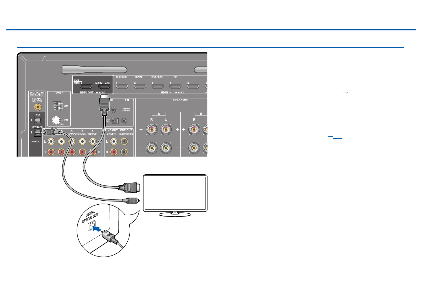
To Non-ARC TV
Contents ≫ Connections ≫ Playback ≫ Setup
If the TV does not support the ARC (Audio Return Channel) function (*), connect
an HDMI cable and digital optical cable.
• If you use a cable set-top box, etc. connected to the input jack of this unit to
watch TV (without using a TV’s built-in tuner), connection with a digital optical
cable or analog audio cable is not required.
• Another TV or projector can be connected to the HDMI OUT SUB jack. Switch
between MAIN and SUB using the "AUDIO Menu" ( p97). Note that this
jack is not ARC-compatible.
• If devices with different resolutions are connected to HDMI OUT MAIN jack
and SUB jack, images are output with the lower resolution.
• If a 4K high-quality video is played, use a Premium High Speed HDMI Cable
or Premium High Speed HDMI Cable with Ethernet whose package has a
"PREMIUM Certied Cable" label. Furthermore, in "Switching the HDMI 4K
Signal Format Input and Output by this Unit" ( p77), change the setting
value to "Enhanced".
• The audio from the connected TV can only be played when the audio is PCM.
To play PCM audio, set the audio output on the TV to PCM output.
ab
(*) ARC function: Transmits the audio signals of the TV via an HDMI cable, and
plays the audio of the TV on this unit. Connection to an ARC-compatible TV is
complete with one HDMI cable. To check if the TV supports the ARC function,
refer to the instruction manual of the TV, etc.
≫
a HDMI cable, b Digital optical cable
TV
27
Front Panel≫ Rear Panel≫ Remote≫
Contents ≫ Connections ≫ Playback ≫ Setup
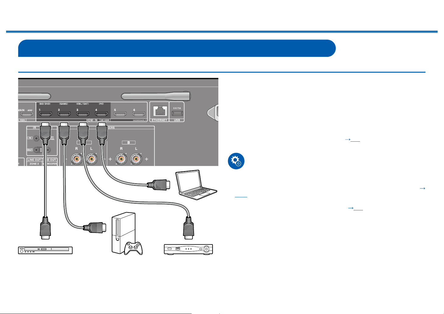
Connecting Playback Devices
Connecting an AV Component with HDMI Jack Mounted
This is a connection example of an AV component equipped with an HDMI jack.
When connecting with an AV component that conforms to the CEC (Consumer
Electronics Control) standard, you can use the HDMI CEC function (*) that
enables linking with input selectors, etc. and the HDMI Standby Through function
that can transmit video and audio signals of the AV component to the TV even if
this unit is in standby mode.
• If a 4K high-quality video is played, use a Premium High Speed HDMI Cable
or Premium High Speed HDMI Cable with Ethernet whose package has a
"PREMIUM Certied Cable" label. Furthermore, in "Switching the HDMI 4K
Signal Format Input and Output by this Unit" ( p77), change the setting
value to "Enhanced".
Setup
a
PC
GAMEBD/DVD Cable/Satellite
set-top box
• The HDMI CEC function and HDMI Standby Through function are
automatically enabled if you select "Yes" for "3. ARC Setup" in Initial Setup (
p100). If "No, Skip" is selected, settings are required in the Setup menu after
Initial Setup is completed. Press SETUP on the remote controller, and select
"5. Hardware" - "HDMI" to make the settings. ( p89)
• The audio from connected AV components can only be played when the audio
is PCM or DSD. To play PCM audio, set the audio output on the AV component
to output PCM.
(*) The HDMI CEC function: This function enables various linking operations
with CEC-compliant devices, such as switching input selectors interlocking with
a CEC-compliant player, switching audio output between TV and this unit or
adjusting the volume using the remote controller of a CEC-compliant TV, and
automatically switching this unit to standby when the TV is turned off.
≫
a HDMI cable
28
Front Panel≫ Rear Panel≫ Remote≫
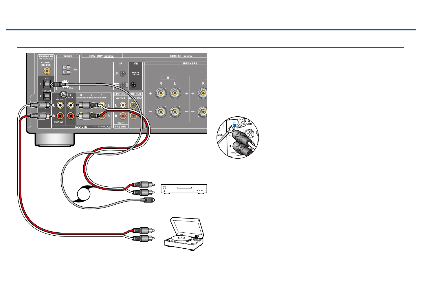
Connecting an Audio Component
a
b
OR
Contents ≫ Connections ≫ Playback ≫ Setup
This is a connection example of an audio component. Connect a CD player using
a digital optical cable or analog audio cable. You can also connect a turntable that
has an MM-type cartridge to the PHONO jack.
• Only PCM audio is supported for input through the DIGITAL IN OPTICAL/
COAXIAL jacks. Set the audio output on the external device to output PCM.
• If the turntable has a built-in phono equalizer, connect it to any of the AUDIO
IN jacks other than the PHONO jack. Further, if the turntable uses an MC type
cartridge, install a phono equalizer compatible with the MC type cartridge
between the unit and the turntable, and then connect it to any of the AUDIO IN
jacks other than the PHONO jack.
If the turntable has a ground wire, connect it to the GND
terminal of this unit.
• By connecting an Onkyo component with RI jack to the unit by using an RI
cable and an analog audio cable, you can link the unit’s power and input
CD
selection and enable operation with this unit’s remote controller. For details,
refer to the instruction manual of the component with the RI jack.
• Part of the function may not operate even if it is connected via RI depending
on the equipment.
• The RI dock function does not work if ZONE 2 is on.
• When connecting an RI dock, you must rename the input selectors on the
unit to make the system link work. Select the GAME input selector to display
"GAME" on the main unit display. Then press and hold RETURN on the main
unit for 3 seconds to switch the display to "DOCK".
≫
a Analog audio cable, b Digital optical cable
Turntable
29
Front Panel≫ Rear Panel≫ Remote≫
Contents ≫ Connections ≫ Playback ≫ Setup
Connecting an AV Component in a Separate Room (Multi-zone Connection)
Connecting a TV (ZONE 2)
While a disc is played on a Blu-ray Disc player in the main room (where this unit
is located), you can play the video and audio of the same Blu-ray Disc player or
another AV component on the TV equipped with an HDMI IN jack in a separate
room (ZONE 2). Note that only the devices connected to the HDMI IN1 to IN3
jacks can be played on the TV in the separate room.
• Audio from an externally connected AV component can be output only when
the audio is 2ch PCM audio signal. Also, the audio output of the AV component
may need to be changed to the PCM output.
Setup
• When video and audio via HDMI input are output to ZONE 2, set "1. Input/
Output Assign" - "TV Out / OSD" - "Zone 2 HDMI" ( p81) to "Use" on the
Setup menu.
≫
a HDMI cable
a
TV
30
Front Panel≫ Rear Panel≫ Remote≫
Loading...