


TA-RW244/144
Stereo Cassette Tape Deck
Instruction Manual
STEREO CASSETTE TAPE DECK RI |
EJECT |
|
|
|
EJECT |
PLAYBACK DECK-A |
|
|
|
|
PLAYBACK/RECORDING DECK-B |
|
DOLBY NR REVERCE MODE |
DUBBING |
AUTO SPACE |
COUNTER |
|
|
NORMAL HIGH |
A/B |
RESET |
||
|
|
|
|
DUBB.STOP |
|
AUTO REVERSE/COMPUTER CONTROL |
|
|
|
|
AUTO REVERSE/COMPUTER CONTROL |
|
|
|
|
REC LEVEL |
|
|
POWER |
|
|
|
|
|
STAND-BY |
|
|
MIN |
MAX |
CONTENTS
Features ................................................ |
2 |
Important safeguards ........................... |
3 |
Precautions .......................................... |
3 |
Control positions and names ............... |
4 |
Setting the voltage selector .................. |
4 |
System connections ............................. |
5 |
Power connections ............................... |
5 |
To play a tape ...................................... |
6 |
Reverse mode function ........................ |
7 |
Recording ............................................ |
8 |
Making good sound recordings ........... |
9 |
Tape dubbing ..................................... |
10 |
Useful recording functions ................ |
11 |
Connecting ONKYO components |
|
for z operation ................................ |
12 |
Handling cassette tapes ...................... |
13 |
Cassette deck maintenance ................ |
14 |
Specifications .................................... |
14 |
Troubleshooting guide ....................... |
15 |
Thank you for your purchase of the ONKYO TA-RW244/144 Cassette Tape Deck.
Please read this manual thoroughly before making connections and plugging in the AC power cord.
Following the instructions in this manual will enable you to obtain optimum performance and maximum listening enjoyment from your new TA-RW244/144.
Please retain this manual for future reference.
Features
Full-logic record/play transports with auto reverse and continuous play
Full-logic controls provide smooth, trouble-free electronic switching, and keep you from having to press the stop button when switching between functions. And auto-reverse/continuous play lets you play both sides of both cassettes in sequence, without having to take out the tapes and flip them over.
Two eight-segment peak-holding fluorescent meters
The easy-to-read FL meters have peak-holding functions, which are indispensable when setting the best record/playback levels.
Four-digit electronic tape counter
The large, clear electronic tape counter shows the current tape position, so you can easily edit and locate specific sections.
CD synchro recording
This feature lets you easily make accurate recordings from a compact disc at a touch of a button, when your tape deck is connected to certain z (remote interactive) compatible ONKYO CD players.
z (Remote Interactive) compatible
If you’re one of the fortunate ones who own other ONKYO components that bear the z mark, simple single-cable connection lets you operate all of the major functions of both transports of your TA-RW244/144 with the other component’s remote. (The remote control supplied with ONKYO z CD players covers Deck-B functions only.)
Other features
•Auto tape selector:Automatically sets the optimum bias and equalization levels for the type of tape you insert.
•Dolby B and C Noise Reduction:Reduces the audibility of undesirable tape hiss while retaining music nuances.
•Auto space rec mute:Inserts precise five-second breaks between songs to give your tapes a more professional touch and to make
music search easier.
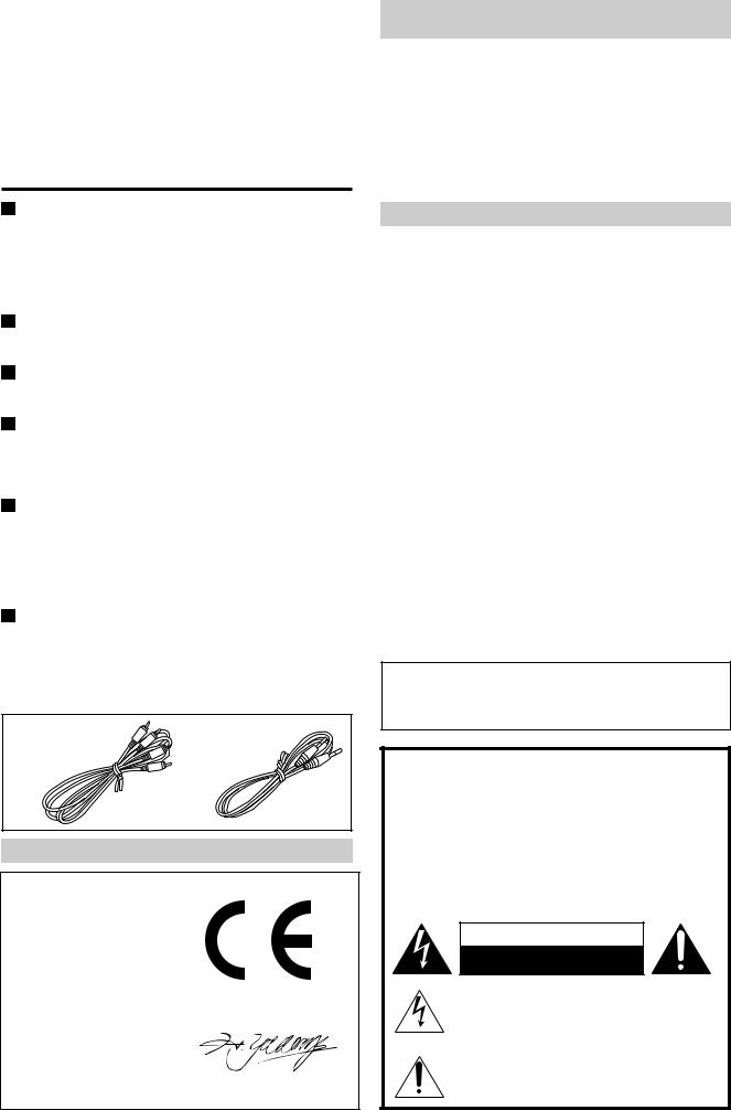
Supplied accessory
Audio connection |
z cable(1) |
cable(2)
FOR EUROPEAN MODEL:
Declaration of Conformity
We, ONKYO EUROPE ELECTRONICS GMBH INDUSTRIESTRASSE 18/20 82110 GERMERING, GERMANY
declare in own responsibility, that the ONKYO product described in this instruction manual is in compliance with the corresponding technical standards such as EN55013, EN55020, EN60555-2, -3 and EN60065
GERMERING,GERMANY
H. YAMAZOE
ONKYO EUROPE ELECTRONICS GMBH
FOR CANADIAN MODEL: (POUR LE MODELE CANADIEN)
• For models having a power cord with a polarized plug CAUTION:TO PREVENT ELECTRIC SHOCK, MATCH
WIDE BLADE OF PLUG TO WIDE SLOT, FULLY INSERT.
• Sur les modèles dont la fiche est polarisée. ATTENTION:POUR ÉVITER LES CHOCS
ÉLECTRIQUES, INTRODUIRE LA LAME LA PLUS LARGE DE LA FICHE DANS LA BORNE CORRESPONDANTE DE LA PRISE ET POUSSER JUSQ’AU FOND.
ATTENTION FOR BRITISH MODEL
Replacement and mounting of an AC plug on the power supply cord of this unit should be performed only by qualified service personnel.
IMPORTANT
The wires in the mains lead are coloured in accordance with the following code:
Blue: Neutral Brown: Live
As the colours of the wires in the mains lead of this appliance may not correspond with the coloured markings identifying the terminals in your plug, proceed as follows:
The wire which is coloured BLUE must be connected to the terminal in the plug which is marked with the letter N or coloured BLACK. The wire which is coloured BROWN must be connected to the terminal in the plug which is marked with the letter L or coloured RED.
IMPORTANT
A 5 amp fuse is fitted in this plug. Should the fuse need to be replaced, please ensure that the replacement fuse has a rating of 5 amps and that it is approved by ASTA or BSI to BS1362. Check for the ASTA mark or the BSI mark on the body of the fuse.
IF THE FITTED MOULDED PLUG IS UNSUITABLE FOR THE SOCKET OUTLET IN YOUR HOME, THEN THE FUSE SHOULD BE REMOVED AND THE PLUG CUT OFF AND DISPOSED OF SAFELY. THERE IS A DANGER OF SEVERE ELECTRICAL SHOCK IF THE CUT OFF PLUG IS INSERTED INTO ANY 13 AMP SOCKET.
If in any doubt, please consult a qualified electrician.
Dolby noise reduction manufactured under license from Dolby Laboratories Licensing Corporation.
“Dolby” and the double-D symbol are trademarks of Dolby Laboratories Licensing Corporation.
WARNING
“TO REDUCE THE RISK OF FIRE OR ELECTRIC SHOCK, DO NOT EXPOSE THIS APPLIANCE TO RAIN OR MOISTURE.”
CAUTION
“TO REDUCE THE RISK OF ELECTRIC SHOCK, DO NOT REMOVE COVER (OR BACK). NO USER-SERVICEABLE PARTS INSIDE. REFER SERVICING TO QUALIFIED SERVICE PERSONNEL.”
WARNING
RISK OF ELECTRIC SHOCK
DO NOT OPEN
•The lightning flash with arrowhead symbol, within an equilateral triangle, is intended to alert the user to the presence of uninsulated “dangerous voltage” within the product’s enclosure that may be of sufficient magnitude to constitute a risk of electric shock to persons.
•The exclamation point within an equilateral triangle is intended to alert the user to the presence of important operating and maintenance (servicing) instructions in
the literature accompanying the appliance.
2

Important safeguards
1.Read Instructions — All the safety and operating instructions should be read before the appliance is operated.
2.Retain Instructions — The safety and operating instructions should be retained for future reference.
3.Heed Warnings — All warnings on the appliance and in the operating instructions should be adhered to.
4.Follow Instructions — All operating and use instructions should be followed.
5.Water and Moisture — The appliance should not be used near water — for example, near a bathtub, washbowl, kitchen sink, laundry tub, in a wet basement, or near a swimming pool, and the like.
6.Carts and Stands — The appliance should be used only with a cart or stand that is recommended by the manufacturer.
6A. An appliance and cart combination should be moved with care. Quick stops, excessive force, and uneven surface may cause the appliance and cart combination to overturn.
PORTABLE CART WARNING
S3125A
7.Wall or Ceiling Mounting — The appliance should be mounted to a wall or ceiling only as recommended by the manufacturer.
8.Ventilation – The appliance should be situated so that its location or position does not interfere with its proper ventilation. For example, the appliance should not be situated on a bed, sofa, rug, or similar surface that may block the ventilation openings; or if placed in a built-in installation, such as a bookcase or cabinet that may impede the flow of air through the ventilation openings, there should be free space of at least 20 cm (8 in.) and open up behind the appliance.
9.Heat — The appliance should be situated away from heat sources such as radiators, heat registers, stoves, or other appliances (including amplifiers) that produce heat.
10.Power Sources — The appliance should be connected to a power supply only of the type described in the operating instructions or as marked on the appliance.
11.Polarization — If the appliance is provided with a polarized plug having one blade wider than the other, please read the following information: The polarization of the plug is a safety feature. The polarized plug will only fit the outlet one way. If the plug does not fit fully into the outlet, try reversing it. If there is still trouble, the user should seek the services of a qualified electrician. Under no circumstances should the user attempt to defeat the polarization of the plug.
12.Power-Cord Protection — Power-supply cords should be routed so that they are not likely to be walked on or pinched by items placed upon or against them, paying particular attention to the cords at plugs, convenience receptacles, and the point where they exit from the appliance.
13.Cleaning — The appliance should be cleaned only as recommended by the manufacturer.
14.Nonuse Periods — The power cord of the appliance should be unplugged from the outlet when left unused for a long period of time.
15.Object and Liquid Entry — Care should be taken so that objects do not fall and liquids are not spilled into the enclosure through openings.
16.Damage Requiring Service — The appliance should be serviced by qualified service personnel when:
A.The power-supply cord or the plug has been damaged; or
B.Objects have fallen, or liquid has been spilled into the appliance; or
C.The appliance has been exposed to rain; or
D.The appliance does not appear to operate normally or exhibits a marked change in performance; or
E.The appliance has been dropped, or the enclosure damaged.
17.Servicing — The user should not attempt to service the appliance beyond that described in the operating instructions. All other servicing should be referred to qualified service personnel.
Precautions
1. Warranty Claim
You can find the serial number on the rear panel of the unit. In case of warranty claim, please report this number.
2. Recording Copyright
Recording of copyrighted material for other than personal use is illegal without permission of the copyright holder.
3.Deck Location
•Do not use or leave in direct sunlight or in other places subject to high temperature and humidity. The unit should also not be left in potentially hot places such as near heating appliances. Excessive heat and moisture can lead to internal damage and serious malfunctions (this also applies to cassette tapes).
The recommended ambient temperature range is 5˚C to 35˚C.
•Avoid damp and dusty places and locations prone to vibrations.
•Be extremely careful with the recording/playback heads. Clean and demagnetize them regularly, but under no circumstances should magnets or other metals be used anywhere near the heads.
•This unit is extremely sensitive to magnetic fields, so do not use near large speakers or other devices which generate magnetic fields.
•Hum may even be induced by magnetic flux leakage from the power transformer in certain amplifiers. Therefore, this unit should also be kept clear of the amplifier.
•Do not remove the cabinet case. If any of the internal parts are handled, there is a considerable danger of electric shock.
4.Cassettes to Avoid:
•Cassettes with poorly formed cases that rattle during rewind and fast forward.
•Low cost cassettes with no guide roller or pressure pad spring should never be used for stereo.
•C-120 cassettes — because the tape and the coating are extremely thin, distortion levels are high. Also, even a slight stretching of the tape will make it susceptible to being caught up in the pinch roller and capstan.
•Endless tapes, if used for a long period of time, can overheat.
5.Power
WARNING
BEFORE PLUGGING IN THE UNIT FOR THE FIRST TIME, READ THE FOLLOWING SECTION CAREFULLY.
•The voltage of the available power supply differs according to country or region. Be sure that the power supply voltage of the area where this unit will be used meets the required voltage (e.g., AC230V 50Hz or AC120V 60Hz) written on the rear panel.
•Voltage Selector (Rear Panel)
Worldwide models are equipped with a voltage selector to conform with local power supplies. Be sure to set this switch to match the power supply in your area before plugging in the unit. Models without a voltage selector can only be used in areas where the power supply voltage is the same as that of the unit. (See page 4)
3

Control positions and names
For more information about a button or control, turn to the page number listed in square brackets([ |
]). |
|
|
|||||||||||||||
1 |
|
2 |
3 |
4 |
5 |
|
|
6 |
7 |
8 |
|
9 |
|
|
|
|
|
|
ONKYO STEREO CASSETTE TAPE DECK RI |
|
EJECT |
|
|
|
|
|
EJECT |
|
|
|
|
|
|
|
|
|
|
|
|
|
DOLBY NR |
REVERCE MODE |
DUBBING |
|
AUTO SPACE |
COUNTER |
|
|
|
|
|
|
|
|
|
|
|
|
|
NORMAL |
HIGH |
A/B |
RESET |
|
|
|
|
|
|
|
|
|
|||
|
|
|
|
|
|
|
|
DUBB.STOP |
|
|
|
|
|
|
|
|
|
|
AUTO REVERCE |
|
|
|
|
|
|
|
|
|
|
|
AUTO REVERCE |
|
|
|
|
|
|
|
PLAYBACK DECK-A |
|
|
|
|
|
|
REC LEVEL |
|
|
PLAYBACK/RECORDING DECK-B |
|
|
|
|
|
||
|
|
POWER |
|
|
|
|
|
|
|
|
|
|
|
|
|
|||
|
|
|
|
|
|
|
|
MIN |
MAX |
|
|
|
|
|
|
|
|
|
|
|
|
14 |
|
|
|
|
|
|
|
|
|
|
|
|
|
|
|
POWER |
|
|
13 12 |
|
11 |
10 |
|
|
|
|
|
|
|
|
|
|||
|
|
|
|
|
|
|
|
|
|
|
|
|
|
|
|
|
|
|
TA-RW144 |
|
|
|
|
|
|
|
a |
|
b |
|
c |
|
|
d |
e |
f |
g |
STAND-BY |
|
|
|
|
|
|
|
|
|
|
|
|||||||
|
|
|
|
|
|
|
|
|
|
|
|
|
|
|
|
|
|
|
STAND-BY/ON |
MAIN POWER |
|
|
|
|
|
|
|
|
|
|
|
|
|
|
|
|
|
TA-RW244 |
|
|
|
|
|
|
DECK-A |
|
|
|
|
|
DOLBY NR |
|
PAUSE |
DECK-B |
||
|
ON |
OFF |
|
|
|
|
|
PLAY |
|
|
|
HI-SPEED |
DUBBING |
OFF |
B C |
REC |
PLAY |
|
STAND-BY |
|
|
|
|
|
|
|
|
|
|
|
|
|
|
|
|
|
|
|
|
|
|
|
|
|
L |
|
|
|
|
|
|
|
|
A |
|
|
|
|
|
|
|
|
|
|
|
|
|
|
|
|
|
|
|
|
|
|
|
|
|
|
|
|
dB |
- |
|
-20 |
-10 |
-6 |
-3 |
0 |
+3 |
+6 |
|
|
|
|
|
|
|
|
|
R |
|
|
|
|
|
|
|
|
B |
|
|
|
|
|
|
|
|
|
|
|
|
|
|
|
j |
|
|
i |
|
h |
Front panel
1.Deck A cassette holder [6]
2.DOLBY NR button [6, 8, 9]
3.Deck A r EJECT button [6]
4.REVERSE MODE button [6, 7, 8, 10]
5.DUBBING button (NORMAL/HIGH) [10]
6.COUNTER A/B button [8]
7.Deck B r EJECT button [8]
8.COUNTER RESET button [8]
9.Deck B cassette holder [8]
10.REC LEVEL control knob [8]
11.Deck B operation buttons t : Rec/pause button [8] AUTO SPACE
:Auto space button [11]
d : Rewind button [7] f : Fast forward button [7]
a: Reverse play button [6, 9]
e : Stop button (DUBB.STOP) [6, 9, 10]
s: Forward play button [6, 9]
12.Deck A operation buttons d : Rewind button [7]
f : Fast forward button [7] a : Reverse play button [6] e : Stop button [6]
s : Forward play button [6]
13.STAND-BY indicator [5]
14.POWER button [5] (TA-RW144) STAND-BY/ON button [5] (TA-RW244) MAIN POWER button [5] (TA-RW244)
Display
a Deck A direction indicator b Reverse mode indicator
c Dubbing indicators d Dolby NR indicators
eo REC indicator
fg PAUSE indicator
gDeck B direction indicator
hCounter
i Deck A/B indicator
jPeak level indicator
Setting the voltage selector (Worldwide model only)
Models without a voltage selector can only be used in areas where the power supply is the same as that of the cassette deck.
|
|
|
|
|
|
1. Determine the proper voltage for your |
|
|
|
MWT |
|
|
|
|
area: 220-230 V or 120 V. |
|
LINE IN LINE OUT |
C A U T I O N |
AVIS |
VOLTAGE SELECTOR |
2. |
If the preset voltage does not conform |
|
L |
L |
MODEL NO. TA-RW244 |
VOLTAGE SELECTOR |
|
to your area, insert a screwdriver into |
||
R |
R |
|
|
|
|
|
|
|
|
|
|
|
|
|
the groove in the switch. Slide the |
|
|
|
|
220-230V |
120V |
|
switch all the way to the right (120 V) |
|
|
|
|
|
|
|
or to the left (220-230 V), whichever is |
|
|
|
|
|
|
|
appropriate. |
4
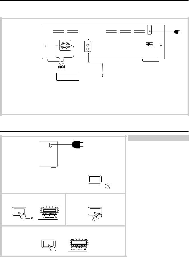
System connections
•Do not plug in the AC power cord until all other connections have been made.
•On each pair of input or output jacks, the lower jack (marked R) corresponds to the right channel, and the upper jack (marked L) to the left channel. Refer to the amplifier’s instruction manual for further information on connections.
Connecting to an amplifier
Connect the tape deck LINE IN jacks to the TAPE REC jacks on the rear panel of the amplifier and the tape deck LINE OUT jacks to the amplifier TAPE PLAY jacks. Refer to the amplifier’s instruction manual for further information on connections.
|
|
|
|
To AC outlet |
LINE IN LINE OUT |
REMOTE |
|
See "Power |
|
(REC) |
(PLAY) |
CONTROL |
VOLTAGE SELECTOR |
connections" |
|
|
|||
L |
L |
|
|
|
|
|
|
220-230V 120V |
below. |
R |
R |
|
|
|
L R L R (REC)(PLAY)
Amplifier
See "Connecting ONKYO components for z operation" on page 12.
Power connections
1
|
|
|
(TA-RW144 only) |
|
|
|
POWER |
|
|
|
STAND-BY |
2 |
|
(TA-RW144) |
(TA-RW244) |
POWER |
|
MAIN POWER |
|
|
STAND-BY |
|
STAND-BY |
3 |
|
(TA-RW244 only) |
|
|
STAND-BY/ON |
|
STAND-BY 
Switching power on
TA-RW144:
1.Plug the AC power cord into a wall outlet.
The STAND-BY indicator will light.
2.Press the POWER button.
The STAND-BY indicator will go out and the display will light.
TA-RW244:
1.Plug the AC power cord into a wall outlet.
2.Press the MAIN POWER button.
The STAND-BY indicator will light.
3.Press the STAND-BY/ON button.
The STAND-BY indicator will go out and the display will light.
•Pressing the a or s button of either Deck A or Deck B when the unit is in standby status will also cause the display to light and playback will start.
•If the tape deck is plugged into the amplifier’s AC outlet, the amplifier’s AC power cord must be plugged into a wall outlet and its power switched on before the tape deck can operate.
5
 Loading...