


 Loading...
AV RECEIVER
HT-R592
Instruction Manual
Contents |
|
Safety Information and Introduction |
............2 |
Table of Contents........................................... |
5 |
Connections ................................................. |
11 |
Turning On & Basic Operations.................. |
18 |
Advanced Operations .................................. |
36 |
Controlling Other Components................... |
51 |
Appendix....................................................... |
57 |
Speaker Package |
|
Remote Control Codes |
|
En
WARNING:
TO REDUCE THE RISK OF FIRE OR ELECTRIC SHOCK, DO NOT EXPOSE THIS APPARATUS TO RAIN OR MOISTURE.
CAUTION:
TO REDUCE THE RISK OF ELECTRIC SHOCK, DO NOT REMOVE COVER (OR BACK). NO USER-SERVICEABLE PARTS INSIDE. REFER SERVICING TO QUALIFIED SERVICE PERSONNEL.
WARNING |
|
AVIS |
RISK OF ELECTRIC SHOCK |
|
RISQUE DE CHOC ELECTRIQUE |
DO NOT OPEN |
|
NE PAS OUVRIR |
|
|
|
The lightning flash with arrowhead symbol, within an equilateral triangle, is intended to alert the user to the presence of uninsulated “dangerous voltage” within the product’s enclosure that may be of sufficient
magnitude to constitute a risk of electric shock to persons.
The exclamation point within an equilateral triangle is intended to alert the user to the presence of important operating and maintenance (servicing) instructions in the literature accompanying the appliance.
Important Safety Instructions
1.Read these instructions.
2.Keep these instructions.
3.Heed all warnings.
4.Follow all instructions.
5.Do not use this apparatus near water.
6.Clean only with dry cloth.
7.Do not block any ventilation openings. Install in accordance with the manufacturer’s instructions.
8.Do not install near any heat sources such as radiators, heat registers, stoves, or other apparatus (including amplifiers) that produce heat.
9.Do not defeat the safety purpose of the polarized or grounding-type plug. A polarized plug has two blades with one wider than the other. A grounding type plug has two blades and a third grounding prong. The wide blade or the third prong are provided for your safety. If the provided plug does not fit into your outlet, consult an electrician for replacement of the obsolete outlet.
10.Protect the power cord from being walked on or pinched particularly at plugs, convenience receptacles, and the point where they exit from the apparatus.
11.Only use attachments/accessories specified by the
manufacturer.
12. Use only with the cart, stand, tripod, bracket, or table
specified by the manufacturer, or sold with the apparatus.
When a cart is used, use caution when moving the
cart/apparatus combination to
S3125A
avoid injury from tip-over.
13.Unplug this apparatus during lightning storms or when unused for long periods of time.
14.Refer all servicing to qualified service personnel. Servicing is required when the apparatus has been damaged in any way, such as power-supply cord or plug is damaged, liquid has been spilled or objects have fallen into the apparatus, the apparatus has been exposed to rain or moisture, does not operate normally, or has been dropped.
15.Damage Requiring Service
Unplug the apparatus from the wall outlet and refer servicing to qualified service personnel under the following conditions:
A.When the power-supply cord or plug is damaged,
B.If liquid has been spilled, or objects have fallen into the apparatus,
C.If the apparatus has been exposed to rain or water,
Safety Information and Introduction
D.If the apparatus does not operate normally by following the operating instructions. Adjust only those controls that are covered by the operating instructions as an improper adjustment of other controls may result in damage and will often require extensive work by a qualified technician to restore the apparatus to its normal operation,
E.If the apparatus has been dropped or damaged in any way, and
F.When the apparatus exhibits a distinct change in performance this indicates a need for service.
16.Object and Liquid Entry
Never push objects of any kind into the apparatus through openings as they may touch dangerous voltage points or short-out parts that could result in a fire or electric shock.
The apparatus shall not be exposed to dripping or splashing and no objects filled with liquids, such as vases shall be placed on the apparatus.
Don’t put candles or other burning objects on top of this unit.
17.Batteries
Always consider the environmental issues and follow local regulations when disposing of batteries.
18.If you install the apparatus in a built-in installation, such as a bookcase or rack, ensure that there is adequate ventilation.
Leave 20 cm (8") of free space at the top and sides and 10 cm (4") at the rear. The rear edge of the shelf or board above the apparatus shall be set 10 cm (4") away from the rear panel or wall, creating a flue-like gap for warm air to escape.
The temperature protection operates if the apparatus attain an abnormal high temperature.
The apparatus cannot operate until it has cooled down.
En-2

Precautions
1.Recording Copyright—Unless it’s for personal use only, recording copyrighted material is illegal without the permission of the copyright holder.
2.AC Fuse—The AC fuse inside the unit is not userserviceable. If you cannot turn on the unit, contact your Onkyo dealer.
3.Care—Occasionally you should dust the unit all over with a soft cloth. For stubborn stains, use a soft cloth dampened with a weak solution of mild detergent and water. Dry the unit immediately afterwards with a clean cloth. Don’t use abrasive cloths, thinners, alcohol, or other chemical solvents, because they may damage the finish or remove the panel lettering.
4.Power WARNING
BEFORE PLUGGING IN THE UNIT FOR THE FIRST TIME, READ THE FOLLOWING SECTION CAREFULLY.
AC outlet voltages vary from country to country. Make sure that the voltage in your area meets the voltage requirements printed on the unit’s rear panel (e.g., AC 230 V, 50 Hz or AC 120 V, 60 Hz).
The power cord plug is used to disconnect this unit from the AC power source. Make sure that the plug is readily operable (easily accessible) at all times.
For models with [POWER] button, or with both [POWER] and [ON/STANDBY] buttons: Pressing the [POWER] button to select OFF mode
does not fully disconnect from the mains. If you do not intend to use the unit for an extended period, remove the power cord from the AC outlet.
For models with [ON/STANDBY] button only: Pressing the [ON/STANDBY] button to select Standby mode does not fully disconnect from the mains. If you do not intend to use the unit for an extended period, remove the power cord from the AC outlet.
5.Preventing Hearing Loss Caution
Excessive sound pressure from earphones and headphones can cause hearing loss.
6.Batteries and Heat Exposure Warning
Batteries (battery pack or batteries installed) shall not be exposed to excessive heat as sunshine, fire or the like.
7.Never Touch this Unit with Wet Hands—Never handle this unit or its power cord while your hands are wet or damp. If water or any other liquid gets inside this unit, have it checked by your Onkyo dealer.
8.Handling Notes
•If you need to transport this unit, use the original packaging to pack it how it was when you originally bought it.
•Do not leave rubber or plastic items on this unit for a long time, because they may leave marks on the case.
•This unit’s top and rear panels may get warm after prolonged use. This is normal.
•If you do not use this unit for a long time, it may not work properly the next time you turn it on, so be sure to use it occasionally.
For U.S. models
FCC Information for User CAUTION:
The user changes or modifications not expressly approved by the party responsible for compliance could void the user’s authority to operate the equipment.
NOTE:
This equipment has been tested and found to comply with the limits for a Class B digital device, pursuant to Part 15 of the FCC Rules. These limits are designed to provide reasonable protection against harmful interference in a residential installation.
En-3
Safety Information and Introduction
This equipment generates, uses and can radiate radio frequency energy and, if not installed and used in accordance with the instructions, may cause harmful interference to radio communications. However, there is no guarantee that interference will not occur in a particular installation. If this equipment does cause harmful interference to radio or television reception, which can be determined by turning the equipment off and on, the user is encouraged to try to correct the interference by one or more of the following measures:
•Reorient or relocate the receiving antenna.
•Increase the separation between the equipment and receiver.
•Connect the equipment into an outlet on a circuit different from that to which the receiver is connected.
•Consult the dealer or an experienced radio/TV technician for help.
For Canadian Models
NOTE: THIS CLASS B DIGITAL APPARATUS COMPLIES WITH CANADIAN ICES-003.
For models having a power cord with a polarized plug: CAUTION: TO PREVENT ELECTRIC SHOCK, MATCH WIDE BLADE OF PLUG TO WIDE SLOT, FULLY INSERT.
Modèle pour les Canadien
REMARQUE: CET APPAREIL NUMÉRIQUE DE LA CLASSE B EST CONFORME À LA NORME NMB-003 DU CANADA.
Sur les modèles dont la fiche est polarisée: ATTENTION: POUR ÉVITER LES CHOCS ÉLECTRIQUES, INTRODUIRE LA LAME LA PLUS LARGE DE LA FICHE DANS LA BORNE CORRESPONDANTE DE LA PRISE ET POUSSER JUSQU’AU FOND.
Supplied Accessories
Make sure you have the following accessories:
Indoor FM antenna ( page 17)
AM loop antenna ( page 17)
Power cord (Brazilian and Taiwanese models) ( page 17)
Speaker cable labels (Taiwanese models) ( page 12)
Speaker setup microphone ( page 26)
Remote controller (RC-863M) and two batteries (AA/R6)
Quick Start Guide
*In catalogs and on packaging, the letter at the end of the product name indicates the color. Specifications and operations are the same regardless of color.
|
Safety Information and Introduction |
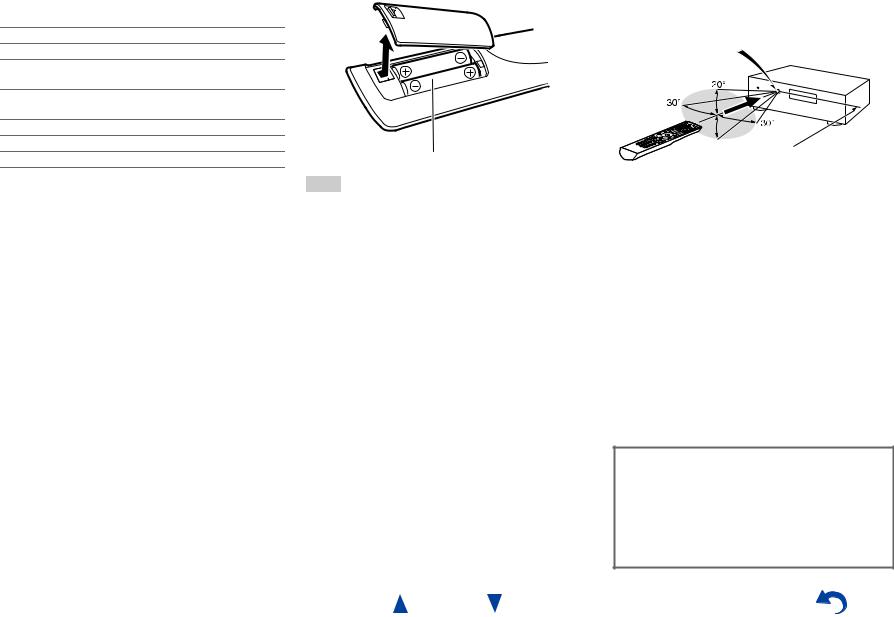
■Installing the batteries |
■Aiming the remote controller |
|
To use the remote controller, point it at the AV receiver’s |
|
remote control sensor, as shown below. |
|
Remote control sensor |
|
AV receiver |
 Approx. 16 ft. (5 m)
Batteries (AA/R6)
Note
•If the remote controller doesn’t work reliably, try replacing the batteries.
•Don’t mix new and old batteries or different types of batteries.
•If you intend not to use the remote controller for a long time, remove the batteries to prevent damage from leakage or corrosion.
•Remove expired batteries as soon as possible to prevent damage from leakage or corrosion.
Thank you for purchasing an Onkyo AV Receiver. Please read this manual thoroughly before making connections and plugging in the unit.
Following the instructions in this manual will enable you to obtain optimum performance and listening enjoyment from your new AV Receiver. Please retain this manual for future reference.
En-4
Table of Contents |
|
Safety Information and Introduction |
|
Important Safety Instructions ...................................... |
2 |
Precautions ................................................................... |
3 |
Supplied Accessories................................................... |
4 |
Table of Contents.......................................................... |
5 |
Features......................................................................... |
6 |
Front & Rear Panels...................................................... |
7 |
Front Panel.................................................................. |
7 |
Display ........................................................................ |
8 |
Rear Panel .................................................................. |
9 |
Remote Controller....................................................... |
10 |
Controlling the AV Receiver...................................... |
10 |
Connections |
|
Connecting the AV Receiver...................................... |
11 |
Connecting Your Speakers ....................................... |
11 |
About AV Connections.............................................. |
13 |
Connecting Components with HDMI ......................... |
14 |
Connecting Your Components.................................. |
15 |
Connecting Onkyo RI Components........................... |
16 |
Connecting a Recording Component ........................ |
16 |
Connecting the Antennas.......................................... |
17 |
Connecting the Power Cord ...................................... |
17 |
Turning On & Basic Operations |
|
Turning On/Off the AV Receiver ................................ |
18 |
Turning On ................................................................ |
18 |
Turning Off ................................................................ |
18 |
Playback ...................................................................... |
19 |
Playing the Connected Component .......................... |
19 |
Controlling Contents of USB Devices ....................... |
20 |
Understanding Icons on the Display ......................... |
21 |
Playing an iPod/iPhone via USB............................... |
21 |
Playing a USB Device ............................................... |
22 |
Listening to AM/FM Radio......................................... |
23 |
Using Basic Functions............................................... |
26 |
|
Using the Automatic Speaker Setup......................... |
26 |
|
Using the Listening Modes ....................................... |
29 |
|
Using the Home Menu .............................................. |
34 |
|
Setting the Display Brightness.................................. |
34 |
|
Using the Sleep Timer .............................................. |
34 |
|
Muting the AV Receiver ............................................ |
34 |
|
Displaying Source Information.................................. |
35 |
|
Changing the Input Display....................................... |
35 |
|
Using the Music Optimizer........................................ |
35 |
|
Using Headphones ................................................... |
35 |
|
Recording ................................................................. |
35 |
|
Advanced Operations |
|
|
On-screen Setup......................................................... |
36 |
|
Common Procedures in Setup Menu........................ |
36 |
|
Setup menu items..................................................... |
37 |
|
1. |
HDMI Input............................................................ |
38 |
2. |
Component (Component Video Input) .................. |
38 |
3. |
Digital Audio (Digital Audio Input) ......................... |
39 |
4. |
Sp Config (Speaker Configuration)....................... |
39 |
5. |
Sp Distance (Speaker Distance)........................... |
40 |
6. |
Level Cal (Level Calibration)................................. |
41 |
7. |
Audio Adjust.......................................................... |
41 |
8. |
Source Setup ........................................................ |
42 |
9. |
Hardware .............................................................. |
45 |
10. HDMI Setup ........................................................ |
46 |
|
Using the Audio Settings .......................................... |
47 |
|
Zone 2 .......................................................................... |
49 |
|
Making Zone 2 Connections ..................................... |
49 |
|
Controlling Zone 2 Components ............................... |
50 |
|
Controlling Other Components |
|
|
iPod/iPhone Playback via Onkyo Dock .................... |
51 |
|
Using the Onkyo Dock .............................................. |
51 |
|
Controlling Your iPod/iPhone.................................... |
52 |
|
Controlling Other Components................................. |
53 |
|
Preprogrammed Remote Control Codes .................. |
53 |
|
Entering Remote Control Codes............................... |
53 |
|
Remapping Colored Buttons..................................... |
53 |
|
Remote Control Codes |
|
|
for Onkyo Components Connected via RI.............. |
54 |
|
Resetting the REMOTE MODE Buttons ................... |
54 |
|
Resetting the Remote Controller .............................. |
54 |
|
Controlling Other Components ................................. |
54 |
|
En-5
Safety Information and Introduction |
|
Appendix |
|
Troubleshooting ......................................................... |
57 |
Connection Tips and Video Signal Path .................. |
62 |
Using an RIHD-compatible TV, Player, |
|
or Recorder .............................................................. |
63 |
About HDMI................................................................. |
65 |
USB Features.............................................................. |
66 |
License and Trademark Information ........................ |
67 |
Specifications ............................................................. |
68 |
To reset the AV receiver to its factory defaults, turn it on and, while holding down VCR/DVR, press
8ON/STANDBY ( page 57).

Features
Amplifier
•80 Watts/Channel @ 8 ohms (FTC)
•130 Watts/Channel @ 6 ohms (IEC)
•160 Watts/Channel @ 6 ohms (JEITA)
•Optimum Gain Volume Circuitry
•H.C.P.S. (High Current Power Supply) Massive High Power Transformer
Processing
•HDMI (Audio Return Channel, 3D, DeepColor, x.v.Color, Lip Sync, DTS-HD Master Audio, DTS-HD High Resolution Audio, Dolby TrueHD, Dolby Digital Plus, DSD and Multi-CH PCM)
•Dolby Pro Logic IIz
•Non-Scaling Configuration
•A-Form Listening Mode Memory
•Direct Mode
•Music Optimizer for Compressed Digital Music files
•192 kHz/24-bit D/A Converters
•Powerful and Highly Accurate 32-bit Processing DSP
•Jitter Cleaning Circuit Technology
Safety Information and Introduction
Connections
•4 HDMI Inputs and 1 Output
•Onkyo pfor System Control
•3 Digital Inputs (1 Optical/2 Coaxial)
•Component Video Switching (2 Inputs/1 Output)
•(North American and Brazilian models) Banana PlugCompatible Speaker Posts
•Powered Zone 2
•Front-Panel USB Input for Memory Devices and iPod®/iPhone® models
*USB input is compatible with iPod/iPhone and Onkyo Bluetooth adapter UBT-1.
Miscellaneous
•40 FM/AM Presets
•Audyssey 2EQ® to correct room acoustic problems
•Audyssey Dynamic EQ® for loudness correction
•Audyssey Dynamic Volume® to maintain optimal listening level and dynamic range
•Crossover Adjustment (40/50/60/70/80/90/100/120/150/200 Hz)
•A/V Sync Control Function (up to 400 ms)
•Auto Standby Function
•On-Screen Display via HDMI
En-6
Safety Information and Introduction
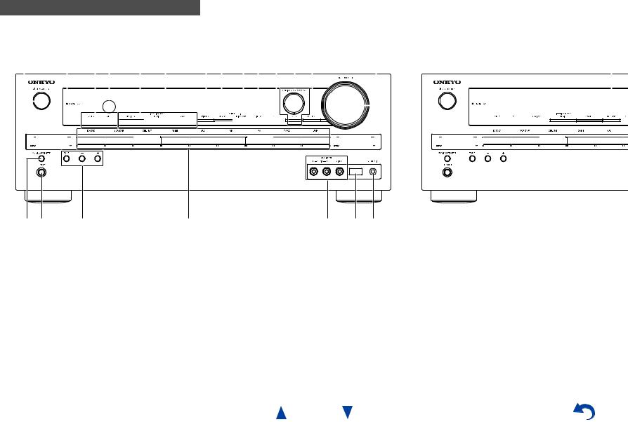
Front & Rear Panels
Front Panel
(North American, Brazilian and Taiwanese models) |
|
|
|
|
|
|
|
|
(Asian models) |
|||||||||||||||||||||||||||||||||||||||||||||||||||||||||||||||||||||||||||||||||||
a b c d e f g h i j k l m |
|
|
|
|
|
n |
|
|
|
|
|
|
|
|
|
|
|
|
|
|
|
|
|
|
|
|
|
|
|
|
v |
|||||||||||||||||||||||||||||||||||||||||||||||||||||||||||||
|
|
|
|
|
|
|
|
|
|
|
|
|
|
|
|
|
|
|
|
|
|
|
|
|
|
|
|
|
|
|
|
|
|
|
|
|
|
|
|
|
|
|
|
|
|
|
|
|
|
|
|
|
|
|
|
|
|
|
|
|
|
|
|
|
|
|
|
|
|
|
|
|
|
|
|
|
|
|
|
|
|
|
|
|
|
|
|
|
|
|
|
|
|
|
|
|
|
|
|
|
|
|
|
|
|
|
|
|
|
|
|
|
|
|
|
|
|
|
|
|
|
|
|
|
|
|
|
|
|
|
|
|
|
|
|
|
|
|
|
|
|
|
|
|
|
|
|
|
|
|
|
|
|
|
|
|
|
|
|
|
|
|
|
|
|
|
|
|
|
|
|
|
|
|
|
|
|
|
|
|
|
|
|
|
|
|
|
|
|
|
|
|
|
|
|
|
|
|
|
|
|
|
|
|
|
|
|
|
|
|
|
|
|
|
|
|
|
|
|
|
|
|
|
|
|
|
|
|
|
|
|
|
|
|
|
|
|
|
|
|
|
|
|
|
|
|
|
|
|
|
|
|
|
|
|
|
|
|
|
|
|
|
|
|
|
|
|
|
|
|
|
|
|
|
|
|
|
|
|
|
|
|
|
|
|
|
|
|
|
|
|
|
|
|
|
|
|
|
|
|
|
|
|
|
|
|
|
|
|
|
|
|
|
|
|
|
|
|
|
|
|
|
|
|
|
|
|
|
|
|
|
|
|
|
|
|
|
|
|
|
|
|
|
|
|
|
|
|
|
|
|
|
|
|
|
|
|
|
|
|
|
|
|
|
|
|
|
|
|
|
|
|
|
|
|
|
|
|
|
|
|
|
|
|
|
|
|
|
|
|
|
|
|
|
|
|
|
|
|
|
|
|
|
|
|
|
|
|
|
|
|
|
|
|
|
|
|
|
|
|
|
|
|
|
|
|
|
|
|
|
|
|
|
|
|
|
|
|
|
|
|
|
|
|
|
|
|
|
|
|
|
|
|
|
|
|
|
|
|
|
|
|
|
|
|
|
|
|
|
|
|
|
|
|
|
|
|
|
|
|
|
|
|
|
|
|
|
|
|
|
|
|
|
|
|
|
|
|
|
|
|
|
|
|
|
|
|
|
|
|
|
|
|
|
|
|
|
|
|
|
|
|
|
|
|
|
|
|
|
|
|
|
|
|
|
|
|
|
|
|
|
|
|
|
|
|
|
|
|
|
|
|
|
|
|
|
|
|
|
|
|
|
|
|
|
|
|
|
|
|
|
|
|
|
|
|
|
|
|
|
|
|
|
|
|
|
|
|
|
|
|
|
|
|
|
|
|
|
|
|
|
|
|
|
|
|
|
|
|
|
|
|
|
|
|
|
|
|
|
|
|
|
|
|
|
|
|
|
|
|
|
|
|
|
|
|
|
|
|
|
|
|
|
|
|
|
|
|
|
|
|
|
|
|
|
|
|
|
|
|
|
|
|
|
|
|
|
|
|
|
|
|
|
|
|
|
|
|
|
|
|
|
|
|
|
|
|
|
|
|
|
|
|
|
|
|
|
|
|
|
|
|
|
|
|
|
|
|
|
|
|
|
|
|
|
|
|
|
|
|
|
|
|
|
|
|
|
|
|
|
|
|
|
|
|
|
|
|
|
|
|
|
|
|
|
|
|
|
|
|
|
|
|
|
|
|
|
|
|
|
|
|
|
|
|
|
|
|
|
|
|
|
|
|
|
|
|
|
|
|
|
|
|
|
|
|
|
|
|
|
|
|
|
|
|
|
|
|
|
|
|
|
|
|
|
|
|
|
|
|
|
|
|
|
|
|
|
|
|
|
|
|
|
|
|
|
|
|
|
|
|
|
|
|
|
|
|
|
|
|
|
|
|
|
|
|
|
|
|
|
|
|
|
|
|
|
|
|
|
|
|
|
|
|
|
|
|
|
|
|
|
|
|
|
|
|
|
|
|
|
|
|
|
|
|
|
|
|
|
|
|
|
|
|
|
|
|
|
|
|
|
|
|
|
|
|
|
|
|
|
|
|
|
|
|
|
|
|
|
|
|
|
|
|
|
|
|
|
|
|
|
|
|
|
|
|
|
|
|
|
|
|
|
|
|
|
|
|
|
|
|
|
|
|
|
|
|
|
|
|
|
|
|
|
|
|
|
|
|
|
|
|
|
|
|
|
|
|
|
|
|
|
|
|
|
|
|
|
|
|
|
|
|
|
|
|
|
|
|
|
|
|
|
|
|
|
|
|
|
|
|
|
|
|
|
|
|
|
|
|
|
|
o p |
q |
r |
s |
t u |
For detailed information, see the pages in parentheses.
a 8ON/STANDBY button (18) b HDMI THRU indicator (46) c ZONE 2, OFF buttons (50) d Remote control sensor (4)
e LISTENING MODE buttons (29) f Display (8)
gDIMMER button (North American, Brazilian and Taiwanese models) (34)
h MEMORY button (24)
i TUNING MODE button (23)
j DISPLAY button (35) k SETUP button (36)
lTUNING q/w, PRESET e/r(23), cursor and
ENTER buttons
m RETURN button
n MASTER VOLUME control (19)
o MUSIC OPTIMIZER button (35, 48) p PHONES jack (35)
q TONE and Tone Level buttons (47) r Input selector buttons (19)
s AUX INPUT AUDIO and VIDEO jacks (15)
t USB port (15, 21, 22)
u SETUP MIC jack (26)
v RT/PTY/TP button (Asian models) (24)
En-7

Safety Information and Introduction
Display
|
ab cd |
e |
f g |
h |
i |
j k l |
j d |
m |
|
|
n o p |
For detailed information, see the pages in parentheses.
a Z2 (Zone 2) indicator (50)
b3D indicator
This lights when a 3D input signal is detected.
c Headphone indicator (35)
d 1, 3and cursor indicators (22)
e Listening mode and format indicators (29, 44)
fAudyssey indicator (26, 42) Dynamic EQ indicator (43) Dynamic Vol indicator (43)
g M.Opt (Music Optimizer) indicator (35, 48)
hTuning indicators
RDS indicator (excluding North American, Brazilian and Taiwanese models) (24) AUTO indicator (23)
TUNED indicator (23)
FM STEREO indicator (23)
i MUTING indicator (34)
jInput indicators (62) HDMI indicator (46, 62) DIGITAL indicator
k ARC (Audio Return Channel) indicator (47) l USB indicator (21, 22)
m Message area
n SLEEP indicator (34)
oChannel/Unit indicators ch indicator
Hz indicator m/ft indicator dB indicator
p ASb (Auto Standby) indicator (45)
En-8

|
|
|
|
|
|
|
|
|
|
|
|
|
|
|
|
|
|
|
|
|
|
|
|
|
|
|
|
|
|
|
|
|
|
|
|
|
|
|
|
|
|
|
|
|
|
|
|
|
|
|
|
|
|
|
|
|
|
|
|
|
|
|
|
|
|
|
|
|
|
|
|
|
|
|
|
|
|
|
|
Safety Information and Introduction |
|||||||||||
|
|
|
|
|
|
|
|
|
|
|
|
|
|
|
|
|
|
|
|
|
|
|
|
|
|
|
|
|
|
|
|
|
|
|
|
|
|
|
|
|
|
|
|
|
|
|
|
|
|
|
|
|
|
|
|
|
|
|
|
|
|
|
|
|
|
|
|
|
|
|
|
|
|
|
|
|
|
|
|
|
|
|
|
|
|
|
|
|
|
|
|
Rear Panel |
|
|
|
|
|
|
|
|
|
|
|
|
|
|
|
|
|
|
|
|
|
|
|
|
|
|
|
|
|
|
|
|
|
|
|
|
|
|
|
|
|
|
|
|
|
|
|
|
|
|
|
|
|
|
|
|
|
|
|
|
|
|
|
|
|
|
|
|
|
|
|
|
|
|
|
|
|
|
|
|
|
|
|
|
|
||||||
(North American and Asian models) |
|
|
|
|
|
|
|
|
|
|
|
|
|
|
|
|
|
|
|
|
|
|
|
|
|
|
|
|
|
|
|
|
|
|
|
|
|
|
|
(Brazilian and Taiwanese models) |
|||||||||||||||||||||||||||||||||||||||||||||||||||
a |
|
|
b |
|
|
|
|
|
c |
|
|
|
|
|
d |
|
|
e |
|
|
f |
|
|
|
|
|
|
|
|
|
|
|
|
|
|
l |
|||||||||||||||||||||||||||||||||||||||||||||||||||||||
|
|
|
|
|
|
|
|
|
|
|
|
|
|
|
|
|
|
|
|
|
|
|
|
|
|
|
|
|
|
|
|
|
|
|
|
|
|
|
|
|
|
|
|
|
|
|
|
|
|
|
|
|
|
|
|
|
|
|
|
|
|
|
|
|
|
|
|
|
|
|
|
|
|
|
|
|
|
|
|
|
|
|
|
|
|
|
|
|
|
|
|
|
|
|
|
|
|
|
|
|
|
|
|
|
|
|
|
|
|
|
|
|
|
|
|
|
|
|
|
|
|
|
|
|
|
|
|
|
|
|
|
|
|
|
|
|
|
|
|
|
|
|
|
|
|
|
|
|
|
|
|
|
|
|
|
|
|
|
|
|
|
|
|
|
|
|
|
|
|
|
|
|
|
|
|
|
|
|
|
|
|
|
|
|
|
|
|
|
|
|
|
|
|
|
|
|
|
|
|
|
|
|
|
|
|
|
|
|
|
|
|
|
|
|
|
|
|
|
|
|
|
|
|
|
|
|
|
|
|
|
|
|
|
|
|
|
|
|
|
|
|
|
|
|
|
|
|
|
|
|
|
|
|
|
|
|
|
|
|
|
|
|
|
|
|
|
|
|
|
|
|
|
|
|
|
|
|
|
|
|
|
|
|
|
|
|
|
|
|
|
|
|
|
|
|
|
|
|
|
|
|
|
|
|
|
|
|
|
|
|
|
|
|
|
|
|
|
|
|
|
|
|
|
|
|
|
|
|
|
|
|
|
|
|
|
|
|
|
|
|
|
|
|
|
|
|
|
|
|
|
|
|
|
|
|
|
|
|
|
|
|
|
|
|
|
|
|
|
|
|
|
|
|
|
|
|
|
|
|
|
|
|
|
|
|
|
|
|
|
|
|
|
|
|
|
|
|
|
|
|
|
|
|
|
|
|
|
|
|
|
|
|
|
|
|
|
|
|
|
|
|
|
|
|
|
|
|
|
|
|
|
|
|
|
|
|
|
|
|
|
|
|
|
|
|
|
|
|
|
|
|
|
|
|
|
|
|
|
|
|
|
|
|
|
|
|
|
|
|
|
|
|
|
|
|
|
|
|
|
|
|
|
|
|
|
|
|
|
|
|
|
|
|
|
|
|
|
|
|
|
|
|
|
|
|
|
|
|
|
|
|
|
|
|
|
|
|
|
|
|
|
|
|
|
|
|
|
|
|
|
|
|
|
|
|
|
|
|
|
|
|
|
|
|
|
|
|
|
|
|
|
|
|
|
|
|
|
|
|
|
|
|
|
|
|
|
|
|
|
|
|
|
|
|
|
|
|
|
|
|
|
|
|
|
|
|
|
|
|
|
|
|
|
|
|
|
|
|
|
|
|
|
|
|
|
|
|
|
|
|
|
|
|
|
|
|
|
|
|
|
|
|
|
|
|
|
|
|
|
|
|
|
|
|
|
|
|
|
|
|
|
|
|
|
|
|
|
|
|
|
|
|
|
|
|
|
|
|
|
|
|
|
|
|
|
|
|
|
|
|
|
|
|
|
|
|
|
|
|
|
|
|
|
|
|
|
|
|
|
|
|
|
|
|
|
|
|
|
|
|
|
|
|
|
|
|
|
|
|
|
|
|
|
|
|
|
|
|
|
|
|
|
|
|
|
|
|
|
|
|
|
|
|
|
|
|
|
|
|
|
|
|
|
|
|
|
|
|
|
|
|
|
|
|
|
|
|
|
|
|
|
|
|
|
|
|
|
|
|
|
|
|
|
|
|
|
|
|
|
|
|
|
|
|
|
|
|
|
|
|
|
|
|
|
|
|
|
|
|
|
|
|
|
|
|
|
|
|
|
|
|
|
|
|
|
|
|
|
|
|
|
|
|
|
|
|
|
g |
h |
i j |
k |
a DIGITAL IN COAXIAL and OPTICAL jacks
b COMPONENT VIDEO IN and OUT jacks
c HDMI IN and OUT jacks
d FM ANTENNA jack and AM ANTENNA terminal
e SUBWOOFER PRE OUT jack
f Power cord (North American and Asian models) g u REMOTE CONTROL jack
hComposite video and analog audio jacks
(BD/DVD IN, VCR/DVR IN and OUT, CBL/SAT IN, GAME IN, TV/CD IN)
i MONITOR OUT V jack j ZONE 2 LINE OUT jacks
kSPEAKERS terminals
(CENTER, FRONT, SURROUND, SURROUND BACK or FRONT HIGH, ZONE 2)
l AC INLET (Brazilian and Taiwanese models)
See “Connecting the AV Receiver” for connection ( pages 11 to 17).
En-9

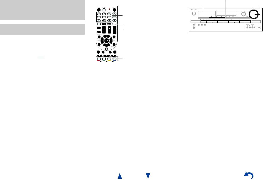
Remote Controller
Controlling the AV Receiver
a*1
b*1 


 g
g
 hc
hc
i*1

 j*1
j*1


 d ac
d ac


d


 k
k  l
l
e


 e
e
bf


 m
m
To control the AV receiver, press RECEIVER to select Receiver mode.
You can also use the remote controller to control Onkyo Blu-ray Disc/DVD player, CD player, and other components.
See “Entering Remote Control Codes” for more details ( page 53).
For detailed information, see the pages in parentheses.
a 8button (18)
b REMOTE MODE/INPUT SELECTOR buttons (19) c q/w/e/rand ENTER buttons
d SETUP button (36)
e Listening Mode buttons (29) f DIMMER button (34)
g TONE and Tone Level buttons (47) h DISPLAY button (35)
i MUTING button (34) j VOL q/wbutton (19) k RETURN button
l HOME button (34) m SLEEP button (34)
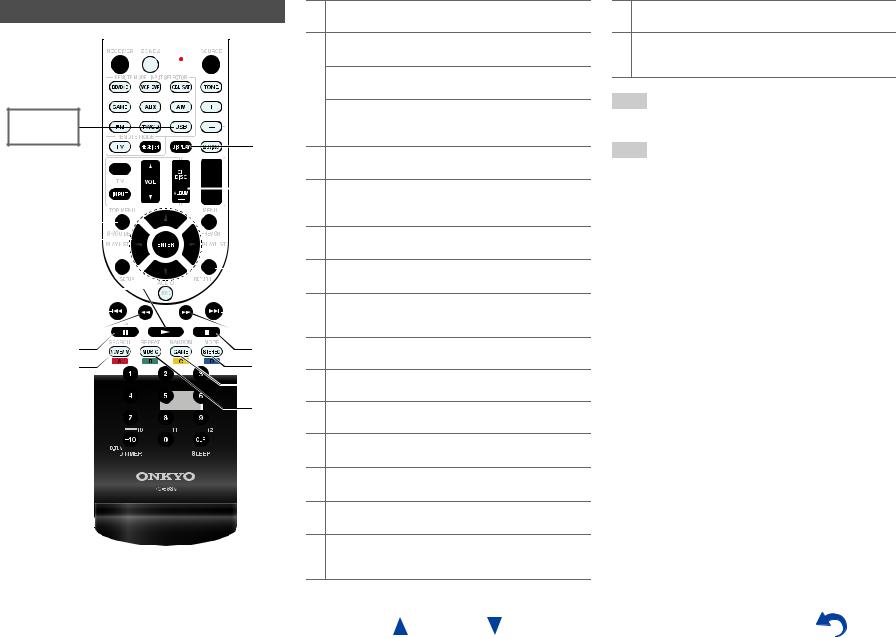
Safety Information and Introduction
Controlling the tuner
To control the AV receiver’s tuner, press AM or FM (or
RECEIVER).
a q/wbuttons (23)
b D.TUN button (23)
c DISPLAY button
d CH +/– button (24)
e Number buttons (23)
*1 These buttons can also be used when a REMOTE MODE other than Receiver mode is selected.
En-10
Connecting the AV
Receiver
Connecting Your Speakers
Speaker Configuration
The following table indicates the channels you should use depending on the number of speakers that you have.
No matter how many speakers you use, a powered subwoofer is recommended for a really powerful and solid bass.
To get the best from your surround sound system, you need to set the speaker settings automatically ( page 26) or manually ( page 39).
Number of speakers |
2 |
3 |
4 |
5 |
6 |
7 |
7 |
Front speakers |
|
|
|
|
|
|
|
|
|
|
|
|
|
|
|
Center speaker |
|
|
|
|
|
|
|
|
|
|
|
|
|
|
|
Surround speakers |
|
|
|
|
|
|
|
|
|
|
|
|
|
|
|
Surround back speaker*1*2 |
|
|
|
|
|
|
|
Surround back speakers*2 |
|
|
|
|
|
|
|
Front high speakers*2 |
|
|
|
|
|
|
|
*1 If you’re using only one surround back speaker, connect it to the SURROUND BACK or FRONT HIGH L terminals.
*2 Front high and surround back speakers cannot be used at the same time.
Connecting the Speaker Cables
The following illustration shows how to connect the speakers to each pair of terminals. If you’re using only one surround back speaker, connect it to the SURROUND BACK or FRONT HIGH L terminals.
Tip
•You can specify whether surround back or front high speakers are connected in the “4. Sp Config (Speaker Configuration)” menu ( page 39) or during Audyssey 2EQ® Room Correction and Speaker Setup ( page 26).
Connections
Surround back/ |
Surround back/ |
|
|
|
|
|
|
|
|
|
|
|
|
|
|
|
|
|
|
|
|
|
|
|
|
|
|
|
|
|
|||||||||||||||||
|
front high |
|
front high |
Surround |
|
Surround |
|
|
|
|
|
||||||||||||||||||||||||||||||||||||
|
right |
|
|
|
|
left |
|
|
|
right |
|
|
|
left |
Center |
||||||||||||||||||||||||||||||||
|
|
|
|
|
|
|
|
|
|
|
|
|
|
|
|
|
|
|
|
|
|
|
|
|
|
|
|
|
|
|
|
|
|
|
|
|
|
|
|
|
|
|
|
|
|
|
|
|
|
|
|
|
|
|
|
|
|
|
|
|
|
|
|
|
|
|
|
|
|
|
|
|
|
|
|
|
|
|
|
|
|
|
|
|
|
|
|
|
|
|
|
|
|
|
|
|
|
|
|
|
|
|
|
|
|
|
|
|
|
|
|
|
|
|
|
|
|
|
|
|
|
|
|
|
|
|
|
|
|
|
|
|
|
|
|
|
|
|
|
|
|
|
|
|
|
|
|
|
|
|
|
|
|
|
|
|
|
|
|
|
|
|
|
|
|
|
|
|
|
|
|
|
|
|
|
|
|
|
|
|
|
|
|
|
|
|
|
|
|
|
|
|
|
|
|
|
|
|
|
|
|
|
|
|
|
|
|
|
|
|
|
|
|
|
|
|
|
|
|
|
|
|
|
|
|
|
|
|
|
|
|
|
|
|
|
|
|
|
|
|
|
|
|
|
|
|
|
|
|
|
|
|
|
|
|
|
|
|
|
|
|
|
|
|
|
|
|
|
|
|
|
|
|
|
|
|
|
|
|
|
|
|
|
|
|
|
|
|
|
|
|
|
|
|
|
|
|
|
|
|
|
|
|
|
|
|
|
|
|
|
|
|
|
|
|
|
|
|
|
|
|
|
|
|
|
|
|
|
|
|
|
|
|
|
|
|
|
|
|
|
|
|
|
|
|
|
|
|
|
|
|
|
|
|
|
|
|
|
|
|
|
|
|
|
|
|
|
|
|
|
|
|
|
|
|
|
|
|
|
|
|
|
|
|
|
|
|
|
|
|
|
|
|
|
|
|
|
|
|
|
|
|
|
|
|
|
|
|
|
|
|
|
|
|
|
|
|
|
|
|
|
|
|
|
|
|
|
|
|
|
|
|
|
|
|
|
|
|
|
|
|
|
|
|
|
|
|
|
|
|
|
|
|
|
|
|
|
|
|
|
|
|
|
|
|
|
|
|
|
|
|
|
|
|
|
|
|
|
|
|
|
|
|
|
|
|
|
|
|
|
|
|
|
|
|
|
|
|
|
|
|
|
|
|
|
|
|
|
|
|
|
|
|
|
|
|
|
|
|
|
|
|
|
|
|
|
|
|
|
|
|
|
|
|
|
|
|
|
|
|
|
|
|
|
|
|
|
|
|
|
|
|
|
|
|
|
|
|
|
|
|
|
|
|
|
|
|
|
|
|
|
|
|
|
|
|
|
|
|
|
|
|
|
|
|
|
|
|
|
|
|
|
|
|
|
|
|
|
|
|
|
|
|
|
|
|
|
|
|
|
|
|
|
|
|
|
|
|
|
|
|
|
|
|
|
|
|
|
|
|
|
|
|
|
|
|
|
|
|
|
|
|
|
|
|
|
|
|
|
|
|
|
|
|
|
|
|
|
|
|
|
|
|
|
|
|
|
|
|
|
|
|
|
|
|
|
|
|
|
|
|
|
|
|
|
|
|
|
|
|
|
|
|
|
|
|
|
|
|
|
|
|
|
|
|
|
|
|
|
|
|
|
|
|
|
|
|
|
|
|
|
|
|
|
|
|
|
|
|
|
|
|
|
|
|
|
|
|
|
|
|
|
|
|
|
|
|
|
|
|
|
|
|
|
|
|
|
|
|
|
|
|
|
|
|
|
|
|
|
|
|
|
|
|
|
|
|
|
|
|
|
|
|
|
|
|
|
|
|
|
|
|
|
|
|
|
|
|
|
|
|
|
|
|
|
|
|
|
|
|
|
|
|
|
|
|
|
|
|
|
|
|
|
|
|
|
|
|
|
|
|
|
|
|
|
|
|
|
|
|
|
|
|
|
|
|
|
|
|
|
|
|
|
|
|
|
|
|
|
|
|
|
|
■Screw-type speaker terminals
Strip 1/2" to 5/8" (12 to 15 mm) of insulation from the ends of the speaker cables, and twist the bare wires tightly, as shown (Supplied speaker cables are already stripped).
1/2" to 5/8" (12 to 15 mm)
Front right |
Front left |
■Push-type speaker terminals
Strip 3/8" to 1/2" (10 to 12 mm) of insulation from the ends of the speaker cables, and twist the bare wires tightly, as shown.
3/8" to 1/2"(10 to 12 mm)
■Banana Plugs (North American and Brazilian models)
•If you are using banana plugs, tighten the speaker terminal before inserting the banana plug.
•Do not insert the speaker code directly into the center hole of the speaker terminal.
En-11

Connecting the Speaker Cables
The speaker terminals are color-coded for identification purpose.
Speaker |
Color |
Front left, Zone 2 left |
White |
|
|
Front right, Zone 2 right |
Red |
|
|
Center |
Green |
|
|
Surround left |
Blue |
|
|
Surround right |
Gray |
|
|
Surround back left, Front high left |
Brown |
|
|
Surround back right, Front high right |
Tan |
|
|
(Taiwanese models) The supplied speaker cable labels are also color-coded and you should attach them to the positive
(+) side of each speaker cable in accordance with the table above. Then all you need to do is to match the color of each label to the corresponding speaker terminal.
•Be careful not to short the positive and negative wires. Doing so may damage the AV receiver.
•Make sure the metal core of the wire does not have contact with the AV receiver’s rear panel. Doing so may damage the AV receiver.
•Don’t connect more than one cable to each speaker terminal. Doing so may damage the AV receiver.
•Don’t connect one speaker to several terminals.
Speaker Connection Precautions
Read the following before connecting your speakers:
• You can connect speakers with an impedance of between 6 and 16 ohms. If you use speakers with a lower impedance, and use the amplifier at high volume levels for a long period of time, the built-in amp protection circuit may be activated.
• Disconnect the power cord from the wall outlet before making any connections.
• Read the instructions supplied with your speakers.
• Pay close attention to speaker wiring polarity. In other words, connect positive (+) terminals only to positive (+) terminals, and negative (–) terminals only to negative (–) terminals. If you get them the wrong way around, the sound will be out of phase and will sound unnatural.
•Unnecessarily long, or very thin speaker cables may affect the sound quality and should be avoided.
En-12
Connections
Using a Powered Subwoofer
LINE INPUT
Powered subwoofer
Corner position
1/3 of wall position
To find the best position for your subwoofer, while playing a movie or some music with good bass, experiment by placing your subwoofer at various positions within the room, and choose the one that provides the most satisfying results.
Tip
•If your subwoofer is unpowered and you’re using an external amplifier, connect the subwoofer pre out jack to an input on the amplifier.
About AV Connections
Connecting AV components |
||||||
HDMI cable |
|
|
|
: Video & Audio |
||
TV, projector, etc. |
|
|
|
|||
|
|
|
|
|
|
|
|
|
|
|
|
AV receiver |
|
|
|
|
|
|
|
|
|
|
|
|
|
|
|
Blu-ray Disc/ |
|
DVD player |
Game console |
Other cables
|
|
|
|
|
: Video |
|
|
: Audio |
|||
|
|
|
|
|
|
|
|||||
TV, projector, etc. |
|
||||||||||
|
|
|
|
|
|
AV receiver |
|
||||
|
|
|
|
|
|||||||
|
|
|
|
|
|
|
|
|
|
|
|
|
|
|
|
|
|
|
|
|
|
|
|
|
|
|
|
|
|
|
|
|
|
|
|
|
|
|
|
|
|
|
|
|
|
|
|
Blu-ray Disc/ |
|
DVD player |
Game console |
•Before making any AV connections, read the manuals supplied with your AV components.
•Don’t connect the power cord until you’ve completed and double-checked all AV connections.
• Push plugs in all the way to make |
|
|
|
|
|
Right! |
|
||||||||||
good connections (loose connections |
|
|
|
|
|
|
|
|
|
|
|
|
|
|
|
|
|
can cause noise or malfunctions). |
|
|
|
|
|
|
|
|
|
|
|
|
|
|
|
|
|
• To prevent interference, keep audio |
|
|
|
|
|
|
|
|
|
|
|
|
|
|
|
|
|
and video cables away from power |
|
|
|
|
|
Wrong! |
|
||||||||||
|
|
|
|
|
|
||||||||||||
|
|
|
|
|
|
||||||||||||
cords and speaker cables. |
|
|
|
|
|
|
|
|
|
|
|
|
|
|
|
|
|
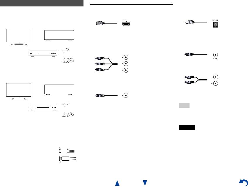
AV Cables and Jacks
■HDMI
HDMI connections can carry digital video and audio.
■Component video
Component video separates the luminance (Y) and color difference signals (PB, PR), providing the best picture quality (some TV manufacturers label their component video sockets slightly differently).
Y |
Green |
PB |
Blue |
PR |
Red |
■Composite video
Composite video is commonly used on TVs, VCRs, and other video equipment.
Yellow
En-13
Connections
■Optical digital audio
Optical digital connections allow you to enjoy digital sound such as PCM*1, Dolby Digital or DTS. The audio quality is the same as coaxial.
■Coaxial digital audio
Coaxial digital connections allow you to enjoy digital sound such as PCM*1, Dolby Digital or DTS. The audio quality is the same as optical.
Orange
■Analog audio (RCA)
Analog audio connections (RCA) carry analog audio.
White
Red
*1 For PCM signals, the supported sampling rates are 32/44.1/48/88.2/96 kHz. With HDMI connections, 176.4 and 192 kHz are also supported.
Note
•The AV receiver does not support SCART plugs.
•The AV receiver’s optical digital jacks have shutter-type covers that open when an optical plug is inserted and close when it’s removed. Push plugs in all the way.
Caution
•To prevent shutter damage, hold the optical plug straight when inserting and removing.

Connections
Connecting Components with HDMI
VCR or DVD recorder/digital video recorder
Game console |
TV, projector, etc. |
|
Satellite/cable set-top box, etc.
*If your TV doesn’t support Audio Return Channel (ARC), you need to connect an optical digital cable together with the HDMI cable to the AV receiver.
*When listening to an HDMI component through the AV receiver, set the HDMI component so that its video can be seen on the TV screen (on the TV, select the input of the HDMI component connected to the AV receiver). If the TV power is off or the TV is set to another input source, this may result in no sound from the AV receiver or the sound may be cut off.
Connect your components to the appropriate jacks. The default input assignments are shown below.
: Assignment can be changed ( page 38).
Jack |
Components |
|
HDMI IN1 |
Blu-ray Disc/DVD player |
|
|
|
|
HDMI IN2 |
VCR or DVD recorder/digital video recorder |
|
|
|
|
HDMI IN3 |
Satellite/cable set-top box, etc. |
|
|
|
|
HDMI IN4 |
Game console |
|
|
|
|
HDMI OUT |
TV, projector, etc. |
|
|
|
|
Blu-ray Disc/DVD player
See also:
•“Connection Tips and Video Signal Path” ( page 62)
•“Using an RIHD-compatible TV, Player, or Recorder” ( page 63)
•“About HDMI” ( page 65)
Tip
•To listen to the audio of a component connected via HDMI through your TV’s speakers, enable “HDMI Through” ( page 46) and set the AV receiver to standby mode.
Note
•In the case of Blu-ray Disc/DVD players, if no sound is output despite following the above-mentioned procedure, set your Bluray Disc/DVD player’s HDMI audio settings to PCM.
Audio Return Channel (ARC) function
Audio Return Channel (ARC) function enables an HDMI capable TV to send the audio stream to the HDMI OUT of the AV receiver.
•This function can be used when:
–Your TV is ARC capable, and
–The TV/CD input selector is selected, and
–“HDMI CEC (RIHD)” is set to “On” ( page 46), and
–“Audio Return Ch (ARC)” is set to “Auto” ( page 47).
En-14
Connecting Your Components
|
|
A B C |
D |
E |
F |
Connect your components to the appropriate jacks. The default input assignments are shown below.
See “Connection Tips and Video Signal Path” for more information ( page 62).
The on-screen menus appear only on a TV that is connected to the HDMI OUT. If your TV is connected to other video outputs, use the AV receiver’s display when changing settings.
: Assignment can be changed ( pages 38, 39).
No. |
Jack/Port |
Components |
|
A |
AUX INPUT |
|
|
|
|
|
|
|
VIDEO |
Camcorder, etc. |
|
|
|
|
|
|
AUDIO L/R |
|
|
|
|
|
|
B |
USB, AUX INPUT |
iPod/iPhone (video |
|
|
VIDEO*1 |
playback) |
|
C |
USB*2 |
iPod/iPhone, MP3 player, |
|
|
|
USB flash drive |
|
|
|
|
|
D |
DIGITAL IN |
|
|
|
|
|
|
|
OPTICAL (TV/CD) |
TV, CD player |
|
|
|
|
|
|
COAXIAL 1 (BD/DVD) |
Blu-ray Disc/DVD player |
|
|
|
|
|
|
COAXIAL 2 (CBL/SAT) |
Satellite/cable set-top box, |
|
|
|
RI dock, etc. |
|
|
|
|
|
E |
COMPONENT VIDEO |
|
|
|
|
|
|
|
IN 1 (BD/DVD) |
Blu-ray Disc/DVD player, |
|
|
|
RI dock |
|
|
|
|
|
|
IN 2 (CBL/SAT) |
Satellite/cable set-top box, |
|
|
|
RI dock, etc. |
|
|
|
|
|
|
OUT |
TV, projector, etc. |
|
|
|
|
|
F |
MONITOR OUT |
TV, projector, etc. |
|
|
|
|
|
|
BD/DVD IN |
Blu-ray Disc/DVD player |
|
|
|
|
|
|
VCR/DVR IN |
VCR, DVD recorder/ |
|
|
|
digital video recorder, RI |
|
|
|
dock |
|
|
|
|
|
|
CBL/SAT IN |
Satellite/cable set-top box, |
|
|
|
etc. |
|
|
|
|
|
|
GAME IN |
Game console, RI dock |
|
|
|
|
|
|
TV/CD IN |
TV, CD player, cassette |
|
|
|
tape deck, MD, CD-R, |
|
|
|
Turntable*3, RI dock |
|
Connections
Note
*1 When USB input is selected, you can input video signals from the AUX INPUT VIDEO jack. Video signals input from AUX INPUT VIDEO will be output from the MONITOR OUT jack.
*2 Do not connect the AV receiver’s USB port to a USB port on your computer. Music on your computer cannot be played through the AV receiver in this way.
*3 Connect a turntable (MM) that has a phono preamp built-in. If your turntable (MM) doesn’t have it, you’ll need a commercially available phono preamp.
If your turntable has a moving coil (MC) type cartridge, you’ll need a commercially available MC head amp or MC transformer as well as a phono preamp. See your turntable’s manual for details.
•With connection D, you can enjoy Dolby Digital and DTS. (To record or listen the audio in Zone 2 as well, use D and F.)
•With connection F, you can listen to and record audio from external components while you are in Zone 2.
•With connection F, if your Blu-ray Disc/DVD player has both the main stereo and multichannel outputs, be sure to connect to the main stereo.
How to record a video source
With the connections described above, you cannot record the videos through the AV receiver. See “Recording” about connections for video recording ( page 35).
En-15
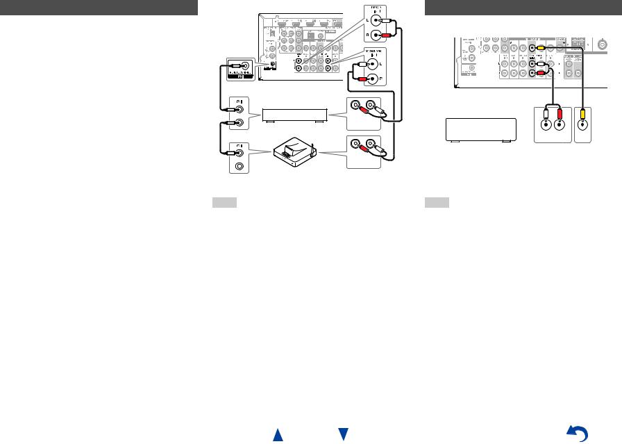
Connecting Onkyo RI Components
1 |
Make sure that each Onkyo component is |
|
connected with an analog audio cable (connection |
|
F in the hookup examples) ( page 15). |
2 |
Make the uconnection (see the illustration). |
3 |
If you’re using an RI Dock or cassette tape deck, |
|
change the Input Display ( page 35). |
With u(Remote Interactive), you can use the following special functions:
System On/Auto Power On
When you start playback on a component connected via uwhile the AV receiver is on standby, the AV receiver will automatically turn on and select that component as the input source.
Direct Change
When playback is started on a component connected via u, the AV receiver automatically selects that component as the input source.
Remote Control
You can use the AV receiver’s remote controller to control your other u-capable Onkyo components, pointing the remote controller at the AV receiver’s remote control sensor instead of the component. You must enter the appropriate remote control code first ( page 54).
R L
ANALOG
AUDIO OUT
e.g., cassette tape deck
R L
ANALOG
AUDIO OUT
RI Dock
Note
•Use only ucables for uconnections. ucables are supplied with Onkyo components.
•Some components have two ujacks. You can connect either one to the AV receiver. The other jack is for connecting additional u-capable components.
•Connect only Onkyo components to ujacks. Connecting other manufacturer’s components may cause a malfunction.
•Some components may not support all ufunctions. Refer to the manuals supplied with your other Onkyo components.
•While Zone 2 is on, the System On/Auto Power On and Direct Change ufunctions do not work.
Connections
Connecting a Recording Component
See “Recording” for details on recording ( page 35).
L R
AUDIO |
VIDEO |
IN |
IN |
VCR, DVD recorder, cassette tape deck, CDR, MD recorder, etc.
Note
•The AV receiver must be turned on for recording. Recording is not possible while it’s in standby mode.
•If you want to record directly from your TV or playback VCR to the recording VCR without going through the AV receiver, connect the TV/VCR’s audio and video outputs directly to the recording VCR’s audio and video inputs. See the manuals supplied with your TV and VCR for details.
•Video signals connected to composite video inputs can be recorded only via composite video outputs. For example, if your TV/VCR is connected to a composite video input, the recording VCR must be connected to a composite video output.
•The surround sound and DSP listening modes cannot be recorded.
•Copy-protected Blu-ray Discs and DVDs cannot be recorded.
•Sources connected to a digital input cannot be recorded. Only analog inputs can be recorded.
•DTS signals will be recorded as noise, so don’t attempt analog recording of DTS CDs or LDs.
En-16
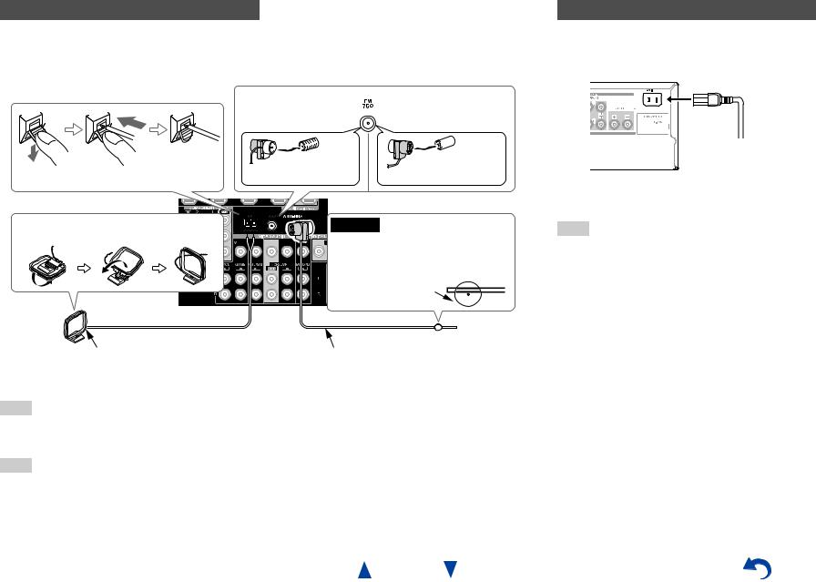
Connecting the Antennas
This section explains how to connect the supplied indoor FM antenna and AM loop antenna.
The AV receiver won’t pick up any radio signals without any antenna connected, so you must connect the antenna to use the tuner.
Connections
Connecting the Power Cord
1 (Brazilian and Taiwanese models) Connect the supplied power cord to the AV receiver’s AC INLET.
Push. |
Insert wire. |
Release. |
Assembling the AM loop antenna
AM loop antenna (supplied)
Note
North American, |
Asian models |
Brazilian and Taiwanese |
|
models |
|
Insert the plug fully |
Insert the plug fully |
into the jack. |
into the jack. |
Caution
 • Be careful not to injure yourself when using thumbtacks.
Thumbtacks, etc.
Indoor FM antenna (supplied)
•Once your AV receiver is ready for use, you’ll need to tune into a radio station and position the antenna to achieve the best possible reception.
•Keep the AM loop antenna as far away as possible from your AV receiver, TV, speaker cables, and power cords.
Tip
•If you cannot achieve good reception with the supplied indoor FM antenna, try a commercially available outdoor FM antenna instead.
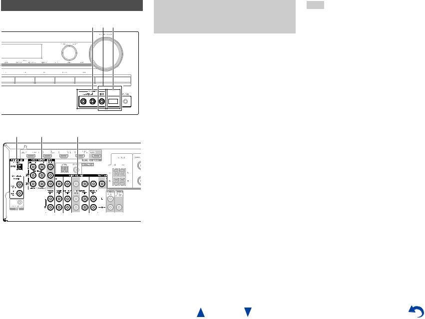
•If you cannot achieve good reception with the supplied indoor AM loop antenna, try using it with a commercially available outdoor AM antenna.
To AC wall outlet
2 Plug the power cord into an AC wall outlet.
Note
•Before connecting the power cord, connect all of your speakers and AV components.
•Turning on the AV receiver may cause a momentary power surge that might interfere with other electrical equipment on the same circuit. If this is a problem, plug the AV receiver into a different branch circuit.
•Do not use a power cord other than the one supplied with the AV receiver. The supplied power cord is designed exclusively for use with the AV receiver and should not be used with any other equipment.
•Never disconnect the power cord from the AV receiver while the other end is still plugged into a wall outlet. Doing so may cause an electric shock. Always disconnect the power cord from the wall outlet first, and then the AV receiver.
En-17

Turning On/Off the AV
Receiver
8ON/STANDBY
8
RECEIVER
|
|
|
Turning On & Basic Operations |
|
|
||
Turning On |
|
Turning Off |
|
1 Press 8ON/STANDBY on the front panel. |
1 Press 8ON/STANDBY on the front panel. |
||
or |
or |
||
Press RECEIVER followed by 8on the remote |
Press RECEIVER followed by 8on the remote |
||
controller. |
controller. |
||
The AV receiver comes on, and its display lights. |
The AV receiver will enter standby mode. To prevent |
||
|
|
any loud surprises when you turn on the AV receiver, |
|
|
|
always turn down the volume before you turn it off. |
|
|
|
|
|
|
|
Tip |
|
|
|
• For details on power management settings, see “Auto Standby” |
|
|
|
( page 45). |
|
En-18
Playback
The on-screen menus appear only on a TV that is connected to the HDMI OUT. If your TV is connected to other video outputs, use the AV receiver’s display when changing settings.
This section describes the procedure for using the remote controller unless otherwise specified.
Turning On & Basic Operations
|
Operating on the AV receiver |
|
Playing the Connected Component |
||
|
||
|
|
Input selector buttons |
|
Operating with the remote controller |
|
LISTENING MODE |
MASTER VOLUME |
INPUT SELECTOR |
|
RECEIVER |
|
VOL q/w |
|
1 Use the input selector buttons to select the input source.
|
Listening mode buttons |
2 |
|
|
3 |
||
1 |
Press RECEIVER followed by an INPUT |
||
|
|||
|
SELECTOR button. |
4 |
|
2 |
Start playback on the source component. |
||
|
|||
|
See also: |
|
•“Playing an iPod/iPhone via USB” ( page 21)
•“Playing a USB Device” ( page 22)
•“Listening to AM/FM Radio” ( page 23)
•“iPod/iPhone Playback via Onkyo Dock” ( page 51)
•“Controlling Other Components” ( page 53)
3 |
To adjust the volume, use VOL q/w. |
4 |
Select a listening mode and enjoy! |
|
See also: |
• “Using the Listening Modes” ( page 29)
Start playback on the source component.
To adjust the volume, use the MASTER VOLUME control.
Select a listening mode and enjoy!
En-19
Controlling Contents of USB Devices
Press USB first.
h
a |
|
|
|
|
|
|
|
|
|
|
|
|
|
|
|
|
i |
||
|
|
|
|
|
|
|
|
|
|
|
|
|
|
|
|
||||
|
|
|
|
|
|
|
|||||||||||||
|
|
|
|
|
|
||||||||||||||
b |
|
|
|
|
|
|
|
|
|
|
|
|
|
|
|
j |
|||
|
|
|
|
|
|
|
|
|
|
|
|
|
|||||||
|
|
|
|
|
|
|
|
|
|
|
|
|
|||||||
|
|
|
|
|
|
|
|
|
|
|
|
|
|
|
|||||
|
|
|
|
|
|||||||||||||||
|
|
|
|
|
|
|
|
|
|
|
|
|
|
|
|
|
|
|
|
|
|
|
|
|
|
|
|
|
|
|
|
|
|
|
|
|
|
|
|
|
|
|
|
|
|
|
|
|
|
|
|
|
|
|
|
|
|
||
c |
|
|
|
|
|
|
|
|
|
||||||||||
|
|
|
|
|
|
||||||||||||||
d |
|
|
|
|
|
|
|
|
k |
||||||||||
|
|
|
|
||||||||||||||||
e |
|
|
|
l |
|||||||||||||||
f |
|
|
|
|
|
|
|
|
m |
||||||||||
|
|
||||||||||||||||||
|
|
||||||||||||||||||
g |
|
|
|
n |
|||||||||||||||
|
|
|
|
|
|
|
|
|
|
|
|
|
|
|
|
|
o |
||
|
|
|
|
|
|
|
|
|
|
|
|
|
|
|
|
|
|
p |
|
|
|
|
|
|
|
|
|
|
|
|
|
|
|
|
|
|
|
|
|
|
|
|
|
|
|
|
|
|
|
|
|
|
|
|
|
|
|
|
|
aTOP MENU
This button displays the top menu for each media or service.
bq/wand ENTER
These buttons navigate through the menus. e/r
This button cycles through pages.
PLAYLIST e/r
In Standard Mode (iPod/iPhone), this button selects playlists.
c1
This button starts playback.
d7
This button selects the beginning of the current song. Pressing this button twice selects the previous song.
e5
This button fast-reverses the current song.
f3
This button pauses playback.
gSEARCH
You can toggle between the playback screen and the list screen during playback.
hDISPLAY
This button switches between song information.
iCH +/–
In Standard Mode (iPod/iPhone), this button selects albums.
jRETURN
This button returns to the previous menu.
k6
This button selects the next song.
l4
This button fast-forwards the current song.
m2
This button stops playback.
nMODE
You can switch between Standard Mode and Extended Mode.
En-20
Turning On & Basic Operations
oRANDOM
This button performs random playback.
pREPEAT
Press this button repeatedly to cycle through the repeat modes.
Tip
•See “Controlling Other Components” about the operation of other components ( page 53).
Note
•The buttons you can use will differ depending on the devices and media used for playback.
Understanding Icons on the Display
This section describes icons that appear on the AV receiver’s display during media playback.
Icon Description
Folder
Track
Playback
Pause
Fast Forward
Fast Reverse
Artist
Album
Repeat One Track
Repeat Folder (USB Device)
Repeat
Shuffle
Shuffle Album (iPod/iPhone)
Playing an iPod/iPhone via USB
The on-screen menus appear only on a TV that is connected to the HDMI OUT.
This section explains how to play music files on the iPod/iPhone.
Compatible iPod/iPhone models Made for:
iPod touch (1st, 2nd, 3rd, 4th and 5th generation), iPod classic, iPod nano (2nd, 3rd, 4th, 5th, 6th and 7th
generation), iPhone 5, iPhone 4S, iPhone 4, iPhone 3GS, iPhone 3G, iPhone
1 |
Press USB to select the “USB” input. |
2 |
Connect the USB cable that comes with the |
|
iPod/iPhone to the USB port on the front of the AV |
|
receiver. |
|
While reading the contents of your iPod/iPhone, the |
|
message “Connecting...” appears on the AV |
|
receiver’s display. |
|
A list of your iPod/iPhone model’s contents appears |
|
(Extended Mode). |
3 |
Use q/wto select a folder, and then press ENTER to |
|
open it. |
Tip
•If you want to operate using the iPod/iPhone or the remote controller, press MODE to switch to Standard mode.
•When you disconnect the iPod/iPhone, the AV receiver remembers the current mode. This means that if you disconnect when in Extended Mode, the AV receiver will start in Extended Mode the next time you connect the iPod/iPhone.
•You can also use the q/w, ENTER and TUNING MODE buttons on the front panel. TUNING MODE allows you to switch modes.
•When connecting your iPod/iPhone with a USB cable, we recommend you use an official USB cable from Apple Inc.
En-21
Turning On & Basic Operations
4 Use q/wto select a music file, and press ENTER or 1to start playback.
Note
•While the message “Connecting...” appears on the AV receiver’s display, do not disconnect the USB cable supplied with your iPod/iPhone or the USB device from the USB port.
•If you connect an iPod or iPhone to the USB port, no sound will be output from the headphones jack.
Extended Mode Control
The content information is displayed (lists are displayed), and you can control the content while looking at the screen. Top screen list:
Playlists, Artists, Albums, Genres, Songs, Composers, Shuffle Songs, Now Playing.
Standard Mode Control
The content information is not displayed, but can be operated using the iPod/iPhone or the remote controller.

Turning On & Basic Operations
Playing a USB Device
The on-screen menus appear only on a TV that is connected to the HDMI OUT.
This section explains how to play music files from a USB device (e.g., USB flash drives and MP3 players).
See also:
• “USB Features” ( page 66).
1
2
3
4
Press USB to select the “USB” input.
Plug your USB device into the AV receiver’s USB port.
While reading the contents of your USB device, the message “Connecting...” appears on the AV receiver’s display.
Press ENTER.
A list of the device’s contents appears. To open a folder, use q/wto select it, and then press ENTER.
Use q/wto select a music file, and press ENTER or 1to start playback.
Note
•While the message “Connecting...” appears on the AV receiver’s display, do not disconnect the USB cable supplied with your iPod/iPhone or the USB device from the USB port.
En-22

Listening to AM/FM Radio
This section describes the procedure using the buttons on the front panel unless otherwise specified.
Using the Tuner
With the built-in tuner you can enjoy AM and FM radio stations. You can store your favorite stations as presets for quick selection.
You can also change the frequency steps ( page 45).
1 Press AM or FM to select either “AM” or “FM”.
In this example, FM has been selected.
Band Frequency
(Actual display depends on the country.)
Tuning into Radio Stations
■Auto tuning mode
1 Press TUNING MODE so that the AUTO indicator lights on the AV receiver’s display.
2 Press TUNING q/w.
Searching stops when a station is found.
When tuned into a station, the TUNED indicator lights. When tuned into a stereo FM station, the FM STEREO indicator lights as shown.
TUNED
AUTO
FM STEREO
Tip
•Tuning into weak FM stereo stations
If the signal from a stereo FM station is weak, it may be impossible to get good reception. In this case, switch to manual tuning mode and listen to the station in mono.
Turning On & Basic Operations
■Manual tuning mode
In manual tuning mode, FM stations will be in mono.
1 |
Press TUNING MODE so that the AUTO indicator |
|
goes off on the AV receiver’s display. |
2 |
Press and hold TUNING q/w. |
|
The frequency stops changing when you release the |
|
button. |
Press the buttons repeatedly to change the frequency one step at a time.
■Tuning into stations by frequency
You can tune into AM and FM stations directly by entering the appropriate frequency.
1 On the remote controller, press AM or FM to select “AM” or “FM”, followed by D.TUN.
(Actual display depends on the country.)
2 Within 8 seconds, use the number buttons to enter the frequency of the radio station.
For example, to tune to 87.5 (FM), press 8, 7, 5 or 8,
7, 5, 0.
If you have entered the wrong number, you can retry after 8 seconds.
En-23
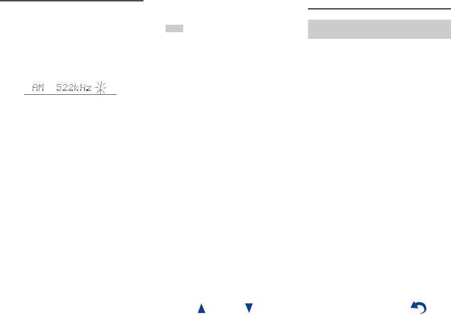
Presetting AM/FM Stations
You can store a combination of up to 40 of your favorite AM/FM radio stations as presets.
1 |
Tune into the AM/FM station that you want to store |
||
|
as a preset. |
||
|
See the previous section. |
||
2 |
Press MEMORY. |
||
|
The preset number flashes. |
||
|
|
|
|
(Actual display depends on the country.)
3 |
While the preset number is flashing (about 8 |
|
seconds), use PRESET e/rto select a preset from |
|
1 through 40. |
4 |
Press MEMORY again to store the station or |
|
channel. |
The station or channel is stored and the preset number stops flashing.
Repeat this procedure for all of your favorite AM/FM radio stations.
■Selecting Presets
1 To select a preset, use PRESET e/ron the AV receiver, or the remote controller’s CH +/–.
Tip
•You can also use the remote controller’s number buttons to select a preset directly.
■Deleting Presets
1 |
Select the preset that you want to delete. |
|
See the previous section. |
2 |
While holding down MEMORY, press TUNING |
|
MODE. |
The preset is deleted and its number disappears from the AV receiver’s display.
Turning On & Basic Operations
Using RDS (excluding North American, Brazilian and Taiwanese models)
RDS works only in areas where RDS broadcasts are available.
When tuned into an RDS station, the RDS indicator lights. When the station is broadcasting text information, the text can be displayed.
■What is RDS?
RDS stands for Radio Data System and is a method of transmitting data in FM radio signals. It was developed by the European Broadcasting Union (EBU) and is available in most European countries. Many FM stations use it these days. In addition to displaying text information, RDS can also help you find radio stations by type (e.g., news, sport, rock, etc.).
The AV receiver supports four types of RDS information:
PS (Program Service)
When tuned to an RDS station that’s broadcasting PS information, the station’s name will be displayed. Pressing DISPLAY will display the frequency for 3 seconds.
RT (Radio Text)
When tuned to an RDS station that’s broadcasting text information, the text will be shown on the AV receiver’s display as described in the next section.
PTY (Program Type)
This allows you to search for RDS radio stations by type ( page 25).
TP (Traffic Program)
This allows you to search for RDS radio stations that broadcast traffic information ( page 25).
En-24

Note
•In some cases, the text characters displayed on the AV receiver may not be identical to those broadcast by the radio station. Also, unexpected characters may be displayed when unsupported characters are received. This is not a malfunction.
•If the signal from an RDS station is weak, RDS data may be displayed intermittently or not at all.
■Displaying Radio Text (RT)
1 Press RT/PTY/TP once.
The RT information scrolls across the AV receiver’s display.
Note
•The message “Waiting” may appear while the AV receiver waits for the RT information.
•If the message “No Text Data” appears, no RT information is available.
■Listening to Traffic News (TP)
You can search for stations that broadcast traffic news.
1 Press RT/PTY/TP three times.
If the current radio station is broadcasting TP (Traffic Program), “[TP]” will appear on the AV receiver’s display. If “TP” without square brackets appears, this means that the station is not broadcasting TP.
2 To locate a station that is broadcasting TP, press
ENTER.
The AV receiver searches until it finds a station that’s broadcasting TP.
If no stations are found, the message “Not Found” appears.
■Finding Stations by Type (PTY)
You can search for radio stations by type.
1 |
Press RT/PTY/TP twice. |
|
The current program type appears on the AV |
|
receiver’s display. |
2 |
Use PRESET e/rto select the type of program |
|
you want. |
|
See the table shown later in this chapter. |
3 |
To start the search, press ENTER. |
|
The AV receiver searches until it finds a station of the |
|
type you specified, at which point it stops briefly |
|
before continuing with the search. |
4 |
When a station you want to listen to is found, press |
|
ENTER. |
If no stations are found, the message “Not Found” appears.
En-25
|
Turning On & Basic Operations |
|
RDS program types (PTY) |
||
|
|
|
Type |
|
Display |
None |
|
None |
|
|
|
News reports |
|
News |
|
|
|
Current affairs |
|
Affairs |
|
|
|
Information |
|
Info |
|
|
|
Sport |
|
Sport |
|
|
|
Education |
|
Educate |
|
|
|
Drama |
|
Drama |
|
|
|
Culture |
|
Culture |
|
|
|
Science and technology |
|
Science |
|
|
|
Varied |
|
Varied |
|
|
|
Pop music |
|
Pop M |
|
|
|
Rock music |
|
Rock M |
|
|
|
Middle of the road music |
|
Easy M |
|
|
|
Light classics |
|
Light M |
|
|
|
Serious classics |
|
Classics |
|
|
|
Other music |
|
Other M |
|
|
|
Weather |
|
Weather |
|
|
|
Finance |
|
Finance |
|
|
|
Children’s programmes |
|
Children |
|
|
|
Social affairs |
|
Social |
|
|
|
Religion |
|
Religion |
|
|
|
Phone in |
|
Phone In |
|
|
|
Travel |
|
Travel |
|
|
|
Leisure |
|
Leisure |
|
|
|
Jazz music |
|
Jazz |
|
|
|
Country music |
|
Country |
|
|
|
National music |
|
Nation M |
|
|
|
Oldies music |
|
Oldies |
|
|
|
Folk music |
|
Folk M |
|
|
|
Documentary |
|
Document |
|
|
|
Alarm test |
|
TEST |
|
|
|
Alarm |
|
Alarm! |
|
|
|
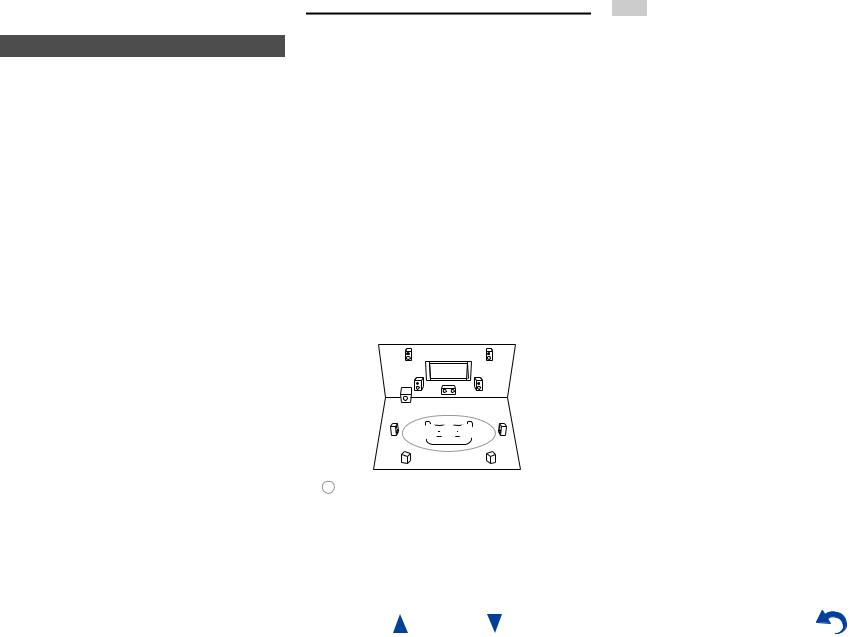
Using Basic Functions
Using the Automatic Speaker Setup
With the supplied calibrated microphone, Audyssey 2EQ® automatically determines the number of speakers connected, their size for purposes of bass management, optimum crossover frequencies to the subwoofer (if present), and distances from the primary listening position. Audyssey 2EQ then removes the distortion caused by room acoustics by capturing room acoustical problems over the listening area in both the frequency and time domain. The result is clear, well-balanced sound for everyone. Audyssey 2EQ can be used with Audyssey Dynamic EQ® and Audyssey Dynamic Volume® ( pages 42, 43). Before using this function, connect and position all of your speakers.
Audyssey 2EQ offers two ways of measuring: the “Audyssey Quick Start” and “Audyssey 2EQ Full Calibration”.
•“Audyssey Quick Start” uses the measurement from one position to perform the speaker setting only.
•“Audyssey 2EQ Full Calibration” uses the measurement from three positions to correct room response in addition to the speaker setting.
The more positions are used in measuring, the better the listening environment will become. We recommend using a measurement from three positions to create the best listening environment.
The Quick Start takes 2 minutes and Full Calibration takes about 10 minutes.
Total measurement time varies depending on the number of speakers.
Measurement procedure
To create a listening environment in your home theater that all listeners will enjoy, Audyssey 2EQ takes measurements at up to three positions within the listening area. Position the microphone at ear height of a seated listener with the microphone tip pointed directly at the ceiling using a tripod. Do not hold the microphone in your hand during measurements as this will produce inaccurate results.
aFirst measurement position
Also referred to as the Main Listening Position, this refers to the most central position where one would normally sit within the listening environment.
Audyssey 2EQ uses the measurements from this position to calculate speaker distance, level, polarity, and the optimum crossover value for the subwoofer.
bSecond measurement position
The right side of the listening area.
cThird measurement position
The left side of the listening area.
The distances from position a to b and a to c must be at least 1 meter (3.3 ft.).
TV
cab
: Listening area |
a to c: Listening position |
En-26
Turning On & Basic Operations
Note
•Make the room as quiet as possible. Background noise and Radio Frequency Interference (RFI) can disrupt the room measurements. Close windows, televisions, radios, air conditioners, fluorescent lights, home appliances, light dimmers, or other devices. Turn off the cell phone (even if it is not in use) or place it away from all audio electronics.
•The microphone picks up test tones played through each speaker as Audyssey 2EQ Room Correction and Speaker Setup runs.
•Audyssey 2EQ Room Correction and Speaker Setup cannot be performed while a pair of headphones is connected.
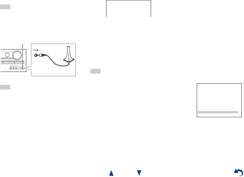
1 Turn on the AV receiver and the connected TV.
On the TV, select the input to which the AV receiver is connected.
Note
•Before plugging the Speaker setup microphone to perform Automatic Speaker Setup, please make sure that all your connected speakers and subwoofers produce sound.
2 Set the speaker setup microphone at the Main Listening Position a, and connect it to the SETUP
MIC jack.
SETUP MIC jack
Speaker setup microphone
The speaker setting menu appears.
Note
•The on-screen menus appear only on a TV that is connected to the HDMI OUT. If your TV is connected to other video outputs, use the AV receiver’s display when changing settings.
3 When you’ve finished making the settings, press
ENTER.
2EQ: Auto Setup |
Audyssey |
Powered Zone 2 |
No |
SurrBk/FrontHigh |
< SurrBack > |
Subwoofer |
Yes |
Perform the “4. Sp Config (Speaker Configuration)” according to your speaker configuration:
–Powered Zone 2 ( page 39)
–SurrBk/FrontHigh ( page 39)
–Subwoofer ( page 39)
If you use a powered subwoofer(s), go to step 4. If not, go to step 5.
4 Adjust the subwoofer volume level to 75 dB, and then press ENTER.
Test tones are played through the subwoofer. Use the volume control on the subwoofer.
Note
•If your subwoofer does not have a volume control, disregard the displayed level and press ENTER to proceed to the next step.
•If you set the subwoofer’s volume control to its maximum and the level displayed is lower than 75 dB, leave the subwoofer’s volume control at its maximum and press ENTER to proceed to the next step.
5 Use q/wto select “Audyssey Quick Start” or
“Audyssey 2EQ Full Calibration”, and then press
ENTER.
Turning On & Basic Operations
6 Press ENTER.
Audyssey 2EQ® Room Correction and Speaker Setup starts.
Test tones are played through each speaker as Audyssey 2EQ Room Correction and Speaker Setup runs. This process takes a few minutes. Please refrain from talking during measurements and do not stand between speakers and the microphone.
Do not disconnect the speaker setup microphone during Audyssey 2EQ Room Correction and Speaker Setup, unless you want to cancel the setup.
If you select “Audyssey Quick Start”, you will go to step 9.
7 Place the speaker setup microphone at the next position, and then press ENTER.
Audyssey 2EQ performs more measurements. This takes a few minutes.
8 |
When prompted, repeat step 7. |
9 |
Use q/wto select an option, and then press ENTER. |
2EQ: Auto Setup |
|
Audyssey |
<- Review Speaker Configuration -> |
||
Subwoofer |
: |
Yes |
Front |
: |
Small |
Center |
: |
Small |
Surround |
: |
Small |
Front High |
: |
None |
Surr Back |
: |
Small |
Surr Back Ch |
: |
2ch |
Crossover |
: |
100Hz |
Save
Cancel
The options are:
`Save:
Save the calculated settings and exit Audyssey 2EQ Room Correction and Speaker Setup.
`Cancel:
Cancel Audyssey 2EQ Room Correction and Speaker Setup.
En-27
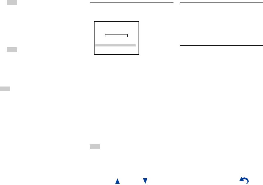
Tip
•You can view the calculated settings for the speaker configuration, speaker distances, and speaker levels by using e/r.
10Use q/wto select a target, and use e/rto change the setting.
After the results of Audyssey 2EQ have been saved, the menu will display the “Audyssey” ( page 42), “Dynamic EQ” ( page 43), “Dynamic Volume” ( page 43) settings.
Note
•When “Audyssey Quick Start” has been used for measurement, “Audyssey” cannot be selected.
•These settings are applied to all input selectors.
11Press ENTER.
12Disconnect the speaker setup microphone.
Note
•You can cancel Audyssey 2EQ Room Correction and Speaker Setup at any point in this procedure simply by disconnecting the setup microphone.
•Do not connect or disconnect any speakers during Audyssey 2EQ Room Correction and Speaker Setup.
•If the AV receiver is muted, it will be unmuted automatically when Audyssey 2EQ Room Correction and Speaker Setup starts.
•Changes to the room after Audyssey 2EQ Room Correction and Speaker Setup requires you run Audyssey 2EQ Room Correction and Speaker Setup again, as room EQ characteristics may have changed.
Error Messages
While Audyssey 2EQ® Room Correction and Speaker Setup is in progress, one of the error messages below may appear.
2EQ: Auto Setup |
Audyssey |
Ambient noise is too high.  Error message
Retry
Cancel
The options are:
`Retry:
Try again.
`Cancel:
Cancel Audyssey 2EQ Room Correction and Speaker Setup.
• Ambient noise is too high.
The background noise is too loud. Remove the source of the noise and try again.
• Speaker Matching Error!
The number of speakers detected was different from that of the first measurement. Check the speaker connection.
• Writing Error!
This message appears if saving fails. Try saving again. If this message appears after 2 or 3 attempts, contact your Onkyo dealer.
• Speaker Detect Error
This message appears if a speaker is not detected. “No” means that no speaker was detected.
Tip
•See “Speaker Configuration” for appropriate settings ( page 11).
Turning On & Basic Operations
Changing the Speaker Setup Manually
You can manually make changes to the settings found during Audyssey 2EQ Room Correction and Speaker Setup.
See also:
•“4. Sp Config (Speaker Configuration)” ( page 39)
•“5. Sp Distance (Speaker Distance)” ( page 40)
•“6. Level Cal (Level Calibration)” ( page 41)
Using a Powered Subwoofer
If you’re using a powered subwoofer and it outputs very low-frequency sound at a low volume level, it may not be detected by Audyssey 2EQ Room Correction and Speaker Setup.
If the “Subwoofer” appears on the “Review Speaker Configuration” screen as “No”, increase the subwoofer’s volume to the half-way point, set it to its highest crossover frequency, and then try running Audyssey 2EQ Room Correction and Speaker Setup again. Note that if the volume is set too high and the sound distorts, detection issues may occur, so use an appropriate volume level. If the subwoofer has a low-pass filter switch, set it to Off or Direct. Refer to your subwoofer’s instruction manual for details.
En-28
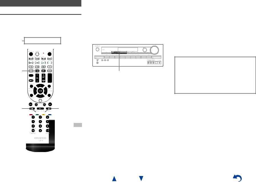
Using the Listening Modes
Selecting Listening Modes
See “About Listening Modes” for detailed information about the listening modes ( page 30).
Listening Mode Buttons
Press RECEIVER first.
MOVIE/TV, MUSIC, GAME
MUSIC |
GAME |
MOVIE/TV 


 STEREO
En-29
Turning On & Basic Operations
MOVIE/TV button
This button selects the listening modes intended for use with movies and TV.
MUSIC button
This button selects the listening modes intended for use with music.
GAME button
This button selects the listening modes intended for use with video games.
STEREO button
This button selects the Stereo listening mode and All Channel Stereo listening mode.
•The Dolby Digital and DTS listening modes can only be selected if your Blu-ray Disc/DVD player is connected to the AV receiver with a digital audio connection (coaxial, optical, or HDMI).
•The listening modes you can select depends on the format of the input signal. To check the format, see “Displaying Source Information” ( page 35).
•While a pair of headphones is connected, you can select the following listening modes: Direct, Stereo, and Mono.
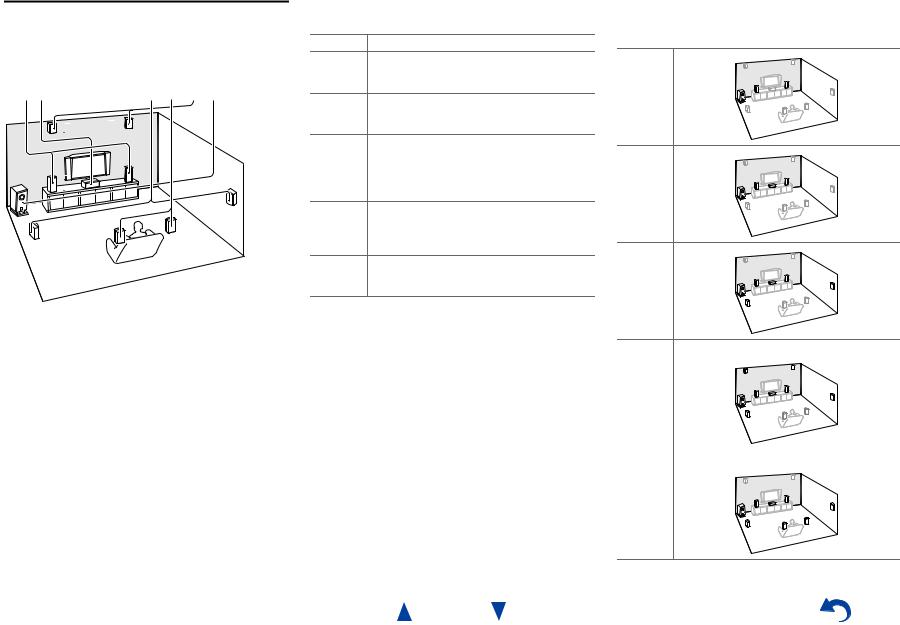
About Listening Modes
The AV receiver’s listening modes can transform your listening room into a movie theater or concert hall, with high fidelity and stunning surround sound.
Explanatory Notes
ab |
c d e f |
a Front speakers b Center speaker
c Surround speakers
d Surround back speakers e Front high speakers
f Subwoofer
Input Source
The following audio formats are supported by the listening mode.
AThis is mono (monophonic) sound.
SThis is stereo (stereophonic) sound. Two independent audio signal channels are reproduced through two speakers.
DThis is 5.1-channel surround sound. This surround system has five main channels of sound and a sixth subwoofer channel (called the point-one channel).
FThis is 7.1-channel surround sound. This is a further sound enhancement to 5.1-channel sound with two additional speakers that provide greater sound envelopment and more accurate positioning of sounds.
GThis is DTS-ES surround sound. This surround system can produce a discrete or a matrix-encoded sixth channel from existing DTS 5.1 encoded material.
HThis is Dolby Digital EX surround sound. This provides a center back surround channel from 5.1- channel sources.
Turning On & Basic Operations
Speaker Layout
The illustration shows which speakers are activated in each channel. See “4. Sp Config (Speaker Configuration)” for the speaker setup ( page 39).
Z
X
C
NB
V
En-30
Loading...