


HT-R990
Table of contents
 Loading...
AV Receiver
HT-R990
Instruction Manual
Thank you for purchasing an Onkyo AV Receiver. Please
read this manual thoroughly before making connections
and plugging in the unit.
Following the instructions in this manual will enable you
to obtain optimum performance and listening enjoyment
from your new AV Receiver.
Please retain this manual for future reference.
Manuel d’instructions
Merci d’avoir porté votre choix sur le ampli-tuner Audio-
Video de Onkyo. Veuillez lire attentivement ce manuel
avant de connecter l’appareil et de le mettre sous tension.
Observez les instructions données dans ce manuel afin de
pouvoir profiter pleinement de votre nouveau ampli-tuner
Audio-Video.
Conservez ce manuel afin de pouvoir le consulter
ultérieurement.
F
r
E
n
English Français
Introduction .............................En-2
Introduction ..............................Fr-2
Connections...........................En-12
Branchements ........................Fr-12
Turning On &
Basic Operations ..............En-21
Mise sous tension et
opérations de base............Fr-21
Advanced Operations ...........En-41
Opérations plus
sophistiquées.....................Fr-41
Controlling
Other Components ...........En-61
Commande d’autres
appareils.............................Fr-61
Appendix................................En-67
Annexe ....................................Fr-67
2
En
Introduction
Important Safety Instructions
1. Read these instructions.
2. Keep these instructions.
3. Heed all warnings.
4. Follow all instructions.
5. Do not use this apparatus near water.
6. Clean only with dry cloth.
7. Do not block any ventilation openings. Install in
accordance with the manufacturer’s instructions.
8. Do not install near any heat sources such as radiators,
heat registers, stoves, or other apparatus (including
amplifiers) that produce heat.
9. Do not defeat the safety purpose of the polarized or
grounding-type plug. A polarized plug has two blades
with one wider than the other. A grounding type plug
has two blades and a third grounding prong. The wide
blade or the third prong are provided for your safety.
If the provided plug does not fit into your outlet,
consult an electrician for replacement of the obsolete
outlet.
10. Protect the power cord from being walked on or
pinched particularly at plugs, convenience receptacles,
and the point where they exit from the apparatus.
11. Only use attachments/accessories specified by the
manufacturer.
12. Use only with the cart, stand,
tripod, bracket, or table
specified by the manufacturer,
or sold with the apparatus.
When a cart is used, use
caution when moving the
cart/apparatus combination to
avoid injury from tip-over.
13. Unplug this apparatus during lightning storms or when
unused for long periods of time.
14. Refer all servicing to qualified service personnel.
Servicing is required when the apparatus has been
damaged in any way, such as power-supply cord or
plug is damaged, liquid has been spilled or objects
have fallen into the apparatus, the apparatus has been
exposed to rain or moisture, does not operate
normally, or has been dropped.
15. Damage Requiring Service
Unplug the apparatus from the wall outlet and refer
servicing to qualified service personnel under the
following conditions:
A. When the power-supply cord or plug is damaged,
B. If liquid has been spilled, or objects have fallen
into the apparatus,
C. If the apparatus has been exposed to rain or water,
D. If the apparatus does not operate normally by
following the operating instructions. Adjust only
those controls that are covered by the operating
instructions as an improper adjustment of other
controls may result in damage and will often
require extensive work by a qualified technician to
restore the apparatus to its normal operation,
E. If the apparatus has been dropped or damaged in
any way, and
F. When the apparatus exhibits a distinct change in
performance this indicates a need for service.
16. Object and Liquid Entry
Never push objects of any kind into the apparatus
through openings as they may touch dangerous
voltage points or short-out parts that could result in a
fire or electric shock.
The apparatus shall not be exposed to dripping or
splashing and no objects filled with liquids, such as
vases shall be placed on the apparatus.
Don’t put candles or other burning objects on top of
this unit.
17. Batteries
Always consider the environmental issues and follow
local regulations when disposing of batteries.
18. If you install the apparatus in a built-in installation,
such as a bookcase or rack, ensure that there is
adequate ventilation.
Leave 20 cm (8") of free space at the top and sides and
10 cm (4") at the rear. The rear edge of the shelf or
board above the apparatus shall be set 10 cm (4")
away from the rear panel or wall, creating a flue-like
gap for warm air to escape.
WARNING:
TO REDUCE THE RISK OF FIRE OR ELECTRIC
SHOCK, DO NOT EXPOSE THIS APPARATUS TO
RAIN OR MOISTURE.
CAUTION:
TO REDUCE THE RISK OF ELECTRIC SHOCK,
DO NOT REMOVE COVER (OR BACK). NO
USER-SERVICEABLE PARTS INSIDE. REFER
SERVICING TO QUALIFIED SERVICE
PERSONNEL.
The lightning flash with arrowhead symbol, within an
equilateral triangle, is intended to alert the user to the
presence of uninsulated “dangerous voltage” within
the product’s enclosure that may be of sufficient
magnitude to constitute a risk of electric shock to
persons.
The exclamation point within an equilateral triangle is
intended to alert the user to the presence of important
operating and maintenance (servicing) instructions in
the literature accompanying the appliance.
WARNING
RISK OF ELECTRIC SHOCK
DO NOT OPEN
RISQUE DE CHOC ELECTRIQUE
NE PAS
OUVRIR
AVIS
PORTABLE CART WARNIN
G
S3125A

3
En
Precautions
1. Recording Copyright—Unless it’s for personal use
only, recording copyrighted material is illegal without
the permission of the copyright holder.
2. AC Fuse—The AC fuse inside the unit is not user-
serviceable. If you cannot turn on the unit, contact
your Onkyo dealer.
3. Care—Occasionally you should dust the unit all over
with a soft cloth. For stubborn stains, use a soft cloth
dampened with a weak solution of mild detergent and
water. Dry the unit immediately afterwards with a
clean cloth. Don’t use abrasive cloths, thinners,
alcohol, or other chemical solvents, because they may
damage the finish or remove the panel lettering.
4. Power
WARNING
BEFORE PLUGGING IN THE UNIT FOR THE
FIRST TIME, READ THE FOLLOWING SECTION
CAREFULLY.
AC outlet voltages vary from country to country.
Make sure that the voltage in your area meets the
voltage requirements printed on the unit’s rear panel
(e.g., AC 230 V, 50 Hz or AC 120 V, 60 Hz).
The power cord plug is used to disconnect this unit
from the AC power source. Make sure that the plug is
readily operable (easily accessible) at all times.
Pressing the [ON/STANDBY] button to select
Standby mode does not fully disconnect from the
mains. If you do not intend to use the unit for an
extended period, remove the power cord from the AC
outlet.
5. Preventing Hearing Loss
Caution
Excessive sound pressure from earphones and
headphones can cause hearing loss.
6. Batteries and Heat Exposure
Warning
Batteries (battery pack or batteries installed) shall not
be exposed to excessive heat as sunshine, fire or the
like.
7. Never Touch this Unit with Wet Hands—Never
handle this unit or its power cord while your hands are
wet or damp. If water or any other liquid gets inside
this unit, have it checked by your Onkyo dealer.
8. Handling Notes
• If you need to transport this unit, use the original
packaging to pack it how it was when you originally
bought it.
• Do not leave rubber or plastic items on this unit for
a long time, because they may leave marks on the
case.
• This unit’s top and rear panels may get warm after
prolonged use. This is normal.
• If you do not use this unit for a long time, it may not
work properly the next time you turn it on, so be
sure to use it occasionally.
For U.S. models
FCC Information for User
CAUTION:
The user changes or modifications not expressly approved
by the party responsible for compliance could void the
user’s authority to operate the equipment.
NOTE:
This equipment has been tested and found to comply with
the limits for a Class B digital device, pursuant to Part 15
of the FCC Rules. These limits are designed to provide
reasonable protection against harmful interference in a
residential installation.
This equipment generates, uses and can radiate radio
frequency energy and, if not installed and used in
accordance with the instructions, may cause harmful
interference to radio communications. However, there is
no guarantee that interference will not occur in a particular
installation. If this equipment does cause harmful
interference to radio or television reception, which can be
determined by turning the equipment off and on, the user
is encouraged to try to correct the interference by one or
more of the following measures:
• Reorient or relocate the receiving antenna.
• Increase the separation between the equipment and
receiver.
• Connect the equipment into an outlet on a circuit
different from that to which the receiver is connected.
• Consult the dealer or an experienced radio/TV
technician for help.
For Canadian Models
NOTE: THIS CLASS B DIGITAL APPARATUS
COMPLIES WITH CANADIAN ICES-003.
For models having a power cord with a polarized plug:
CAUTION: TO PREVENT ELECTRIC SHOCK,
MATCH WIDE BLADE OF PLUG TO WIDE SLOT,
FULLY INSERT.
Modèle pour les Canadien
REMARQUE: CET APPAREIL NUMÉRIQUE DE
LA CLASSE B EST CONFORME À LA NORME NMB-
003 DU CANADA.
Sur les modèles dont la fiche est polarisée:
ATTENTION: POUR ÉVITER LES CHOCS
ÉLECTRIQUES, INTRODUIRE LA LAME LA PLUS
LARGE DE LA FICHE DANS LA BORNE
CORRESPONDANTE DE LA PRISE ET POUSSER
JUSQU’AU FOND.
4
En
For British models
Replacement and mounting of an AC plug on the power
supply cord of this unit should be performed only by
qualified service personnel.
IMPORTANT
The wires in the mains lead are coloured in accordance
with the following code:
Blue: Neutral
Brown: Live
As the colours of the wires in the mains lead of this
apparatus may not correspond with the coloured markings
identifying the terminals in your plug, proceed as follows:
The wire which is coloured blue must be connected to the
terminal which is marked with the letter N or coloured
black.
The wire which is coloured brown must be connected to
the terminal which is marked with the letter L or coloured
red.
IMPORTANT
The plug is fitted with an appropriate fuse. If the fuse
needs to be replaced, the replacement fuse must approved
by ASTA or BSI to BS1362 and have the same ampere
rating as that indicated on the plug. Check for the ASTA
mark or the BSI mark on the body of the fuse.
If the power cord’s plug is not suitable for your socket
outlets, cut it off and fit a suitable plug. Fit a suitable fuse
in the plug.
For European Models
Supplied Accessories
Make sure you have the following accessories:
*
In catalogs and on packaging, the letter at the end of the product
name indicates the color. Specifications and operations are the
same regardless of color.
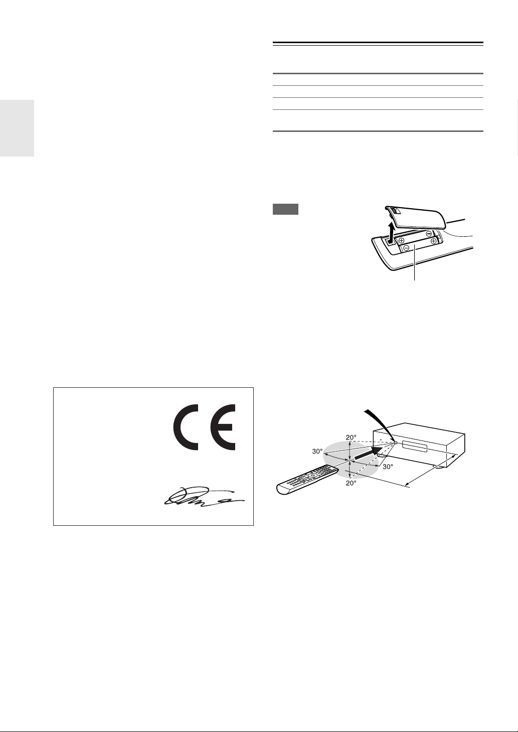
■ Installing the batteries
Note
• If the remote controller
doesn’t work reliably,
try replacing the
batteries.
• Don’t mix new and old
batteries or different
types of batteries.
• If you intend not to use
the remote controller for a long time, remove the batteries to
prevent damage from leakage or corrosion.
• Remove expired batteries as soon as possible to prevent damage
from leakage or corrosion.
■ Aiming the remote controller
To use the remote controller, point it at the AV receiver’s
remote control sensor, as shown below.
Declaration of Conformity
We,
ONKYO EUROPE
ELECTRONICS GmbH
LIEGNITZERSTRASSE 6,
82194 GROEBENZELL,
GERMANY
GROEBENZELL, GERMANY
ONKYO EUROPE ELECTRONICS GmbH
K. MIYAGI
declare in own responsibility, that the ONKYO product
described in this instruction manual is in compliance with the
corresponding technical standards such as EN60065,
EN55013, EN55020 and EN61000-3-2, -3-3.
Indoor FM antenna (➔ page 20)
AM loop antenna (➔ page 20)
Speaker setup microphone (➔ page 30)
Remote controller (RC-801M) and two batteries
(AA/R6)
Batteries (AA/R6)
Remote control sensor
AV receiver
Approx. 16 ft. (5 m)

5
En
Contents
Important Safety Instructions ......................................... 2
Precautions....................................................................... 3
Supplied Accessories...................................................... 4
Features ............................................................................6
Front & Rear Panels......................................................... 8
Front Panel..................................................................... 8
Display............................................................................ 9
Rear Panel ................................................................... 10
Remote Controller.......................................................... 11
Controlling the AV Receiver .........................................11
Connecting the AV Receiver ......................................... 12
Connecting Your Speakers .......................................... 12
About AV Connections .................................................15
Connecting Components with HDMI ............................16
Connecting Your Components ..................................... 17
Connecting Onkyo u Components ............................ 19
Connecting a Recording Component ...........................19
Connecting the Antennas............................................. 20
Connecting the Power Cord .........................................20
Turning On/Off the AV Receiver ................................... 21
Turning On ................................................................... 21
Turning Off ................................................................... 21
Playback.......................................................................... 22
Selecting the Language for the Onscreen
Setup Menus.............................................................. 22
Playing the Connected Component.............................. 22
Controlling Contents of USB or Network Devices ........ 22
Understanding Icons on the Display............................. 23
Playing an iPod/iPhone via USB ..................................23
Playing a USB Device ..................................................24
Listening to Internet Radio ........................................... 24
Playing Music Files on a Server ................................... 26
Remote Playback .........................................................26
Listening to AM/FM Radio ............................................ 27
Using Basic Functions .................................................. 30
Using the Automatic Speaker Setup ............................ 30
Using the Listening Modes........................................... 33
Using the Home Menu.................................................. 39
Using the Sleep Timer.................................................. 39
Setting the Display Brightness ..................................... 39
Displaying Source Information ..................................... 40
Changing the Input Display ..........................................40
Muting the AV Receiver................................................ 40
Using Headphones....................................................... 40
Recording..................................................................... 40
Advanced Setup .............................................................41
On-screen Setup Menus............................................... 41
Common Procedures in Setup Menu ...........................41
Input/Output Assign ......................................................42
Speaker Setup.............................................................. 43
Audio Adjust .................................................................47
Source Setup................................................................ 48
Listening Mode Preset.................................................. 53
Miscellaneous............................................................... 53
Hardware Setup............................................................ 54
Remote Controller Setup ..............................................57
Lock Setup.................................................................... 57
Using the Audio Settings ..............................................57
Zone 2.............................................................................. 59
Making Zone 2 Connections......................................... 59
Controlling Zone 2 Components................................... 60
iPod/iPhone Playback via Onkyo Dock ........................61
Using the Onkyo Dock.................................................. 61
Controlling Your iPod/iPhone .......................................62
Controlling Other Components.....................................64
Preprogrammed Remote Control Codes ......................64
Looking up for Remote Control Code ...........................64
Entering Remote Control Codes................................... 64
Remote Control Codes for Onkyo Components
Connected via u...................................................... 65
Resetting REMOTE MODE Buttons ............................. 65
Resetting the Remote Controller ..................................65
Controlling Other Components .....................................65
Troubleshooting .............................................................67
Network/USB Features...................................................73
Firmware Update ............................................................76
Connection Tips and Video Signal Path ...................... 79
About HDMI..................................................................... 81
Using an RIHD-compatible TV, Player, or Recorder ... 82
Specifications .................................................................84
Video Resolution Chart..................................................85
Introduction
Connections
Turning On & Basic Operations
Advanced Operations
Controlling Other Components
Appendix
To reset the AV receiver to its factory defaults, turn
it on and, while holding down VCR/DVR, press
8ON/STANDBY (➔ page 67).

6
En
Features
Amplifier
• 80 Watts/Channel @ 8 ohms (FTC)
• 130 Watts/Channel @ 6 ohms (IEC)
• Optimum Gain Volume Circuitry
• H.C.P.S. (High Current Power Supply) Massive High
Power Transformer
• Jitter Cleaning Circuit Technology
Processing
•THX
*1
Integrated System Certified
• THX Surround EX
*1
, THX I/S
*1
Cinema, THX Music
Mode
• Incorporates Qdeo™
*2
technology for HDMI Video
Upscaling (to 4K Compatible)
• HDMI (Audio Return Channel, 3D, DeepColor,
x.v.Color
*3
, Lip Sync, DTS-HD Master Audio
*4
,
DTS-HD High Resolution Audio, Dolby TrueHD
*5
,
Dolby Digital Plus, DSD and Multi-CH PCM)
• Dolby TrueHD
*5
and DTS-HD Master Audio
*4
• Dolby Pro Logic IIz
*5
• Non-Scaling Configuration
• A-Form Listening Mode Memory
• Direct Mode
• Music Optimizer
*7
for Compressed Digital Music files
• 192 kHz/24-bit D/A Converters
• Powerful and Highly Accurate 32-bit Processing DSP
Connections
• 4 HDMI
*8
Inputs and 1 Output
• Onkyo p for System Control
• 4 Digital Inputs (2 Optical/2 Coaxial)
• Component Video Switching (2 Inputs/1 Output)
• Universal Port for the Dock for iPod
®
/iPhone
®
*9
/
HD Radio™
*10
tuner module (North American
models)/DAB+ tuner module (European models)
• Banana Plug-Compatible Speaker Posts
*11
• Powered Zone 2
• Analog RGB Video Input (D-sub 15) for PC
• Internet Radio Connectivity (SiriusXM Internet
Radio/vTuner/Last.fm/Pandora/Rhapsody/Slacker/
Mediafly/Napster)
*
Services available may vary depending on the region.
• Network Capability for Streaming Audio Files
*12
• Front-Panel USB Input for Memory Devices and
iPod
®
/iPhone
®
*9
models (Enables Display of Album
Artwork)
Miscellaneous
• 40 AM/FM Presets
• Audyssey 2EQ
®
*6
to correct room acoustic problems
• Audyssey Dynamic EQ
®
*6
for loudness correction
• Audyssey Dynamic Volume
®
*6
to maintain optimal
listening level and dynamic range
• A/V Sync Control Function (up to 800 ms)
• Auto Standby Function
• On-Screen Display via HDMI
• Preprogrammed u-Compatible Remote
7
En
*1
THX and the THX logo are trademarks of THX Ltd. which
are registered in some jurisdictions. All rights reserved.
*2
Qdeo and QuietVideo are trademarks of Marvell or its
affiliates.
*3
“x.v.Color” is a trademark of Sony Corporation.
*4
Manufactured under license under U.S. Patent #’s: 5,451,942;
5,956,674; 5,974,380; 5,978,762; 6,226,616; 6,487,535;
7,212,872; 7,333,929; 7,392,195; 7,272,567 & other U.S. and
worldwide patents issued & pending. DTS and the Symbol are
registered trademarks, & DTS-HD, DTS-HD Master Audio,
and the DTS logos are trademarks of DTS, Inc. Product
includes software.
© DTS, Inc. All Rights Reserved.
*5
Manufactured under license from Dolby Laboratories. Dolby,
Pro Logic, Surround EX and the double-D symbol are
trademarks of Dolby Laboratories.
*6
Manufactured under license from Audyssey Laboratories™,
Inc. U.S. and foreign patents pending. Audyssey 2EQ
®
,
Audyssey Dynamic EQ
®
and Audyssey Dynamic Volume
®
are registered trademarks of Audyssey Laboratories, Inc.
*7
Music Optimizer™ is a trademark of Onkyo Corporation.
*8
“HDMI, the HDMI Logo, and High-Definition Multimedia
Interface are trademarks or registered trademarks of HDMI
Licensing LLC in the United States and other countries.”
*9
iPhone, iPod, iPod classic, iPod nano, iPod shuffle, and
iPod touch are trademarks of Apple Inc., registered in the U.S.
and other countries.
“Made for iPod” and “Made for iPhone” mean that an
electronic accessory has been designed to connect specifically
to iPod or iPhone, respectively, and has been certified by the
developer to meet Apple performance standards. Apple is not
responsible for the operation of this device or its compliance
with safety and regulatory standards.
Please note that the use of this accessory with iPod or iPhone
may affect wireless performance.
*10
HD Radio™, HD Radio Ready™, and the HD Radio Ready
logo are proprietary trademarks of iBiquity Digital
Corporation.
This HD Radio Ready™ receiver is ready to receive
HD Radio broadcasts when connected to the Onkyo UP-HT1
HD Radio tuner module (sold separately).
*11
In Europe, using banana plugs to connect speakers to an audio
amplifier is prohibited.
*12
“DLNA
®
, the DLNA Logo and DLNA CERTIFIED™ are
trademarks, service marks, or certification marks of the
Digital Living Network Alliance.”
*12
Windows and the Windows logo are trademarks of the
Microsoft group of companies.
THX
The HT-R990, jointly developed by Onkyo and THX
Ltd., provides home theater enthusiasts the perfect blend
of performance and ease of use. All of the components in
this THX Certified System are engineered to work seam-
lessly together to deliver exceptional entertainment expe-
riences. Whether you are watching a movie, listening to
music, or playing the hottest new video game, the
HT-R990 will transform your room into the ultimate
entertainment environment.
8
En
Front & Rear Panels
(North American models)
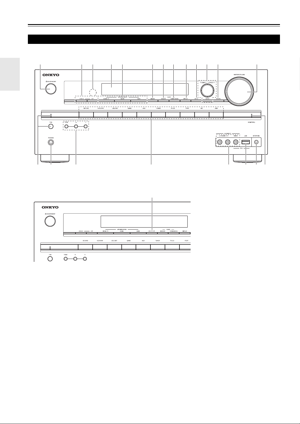
The page numbers in parentheses show where you can find the main explanation for each item.
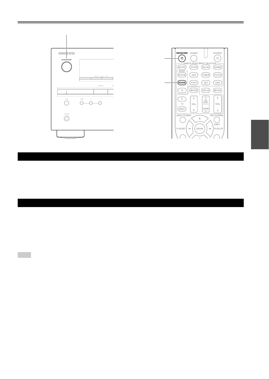
a 8ON/STANDBY button (21)
b ZONE 2, OFF buttons (60)
c Remote control sensor (4)
d Display (9)
e LISTENING MODE buttons (33)
f DIMMER button (North American models) (39)
g MEMORY button (28)
h TUNING MODE button (27)
i DISPLAY button (40)
j SETUP button (41)
k TUNING, PRESET (27 to 28), arrow and ENTER
buttons
l RETURN button
m MASTER VOLUME control (22)
n THX button and indicator (33)
o PHONES jack (40)
p TONE and Tone Level buttons (57)
q Input selector buttons (22)
r AUX INPUT AUDIO/VIDEO jacks (17)
s USB port (17)
t SETUP MIC jack (30)
u HDMI THRU indicator (55)
v RT/PTY/TP button (European models) (29)
Front Panel
qpr
tu
s
o
n
abcdeg
fhijkl m
v
(European models)
9
En
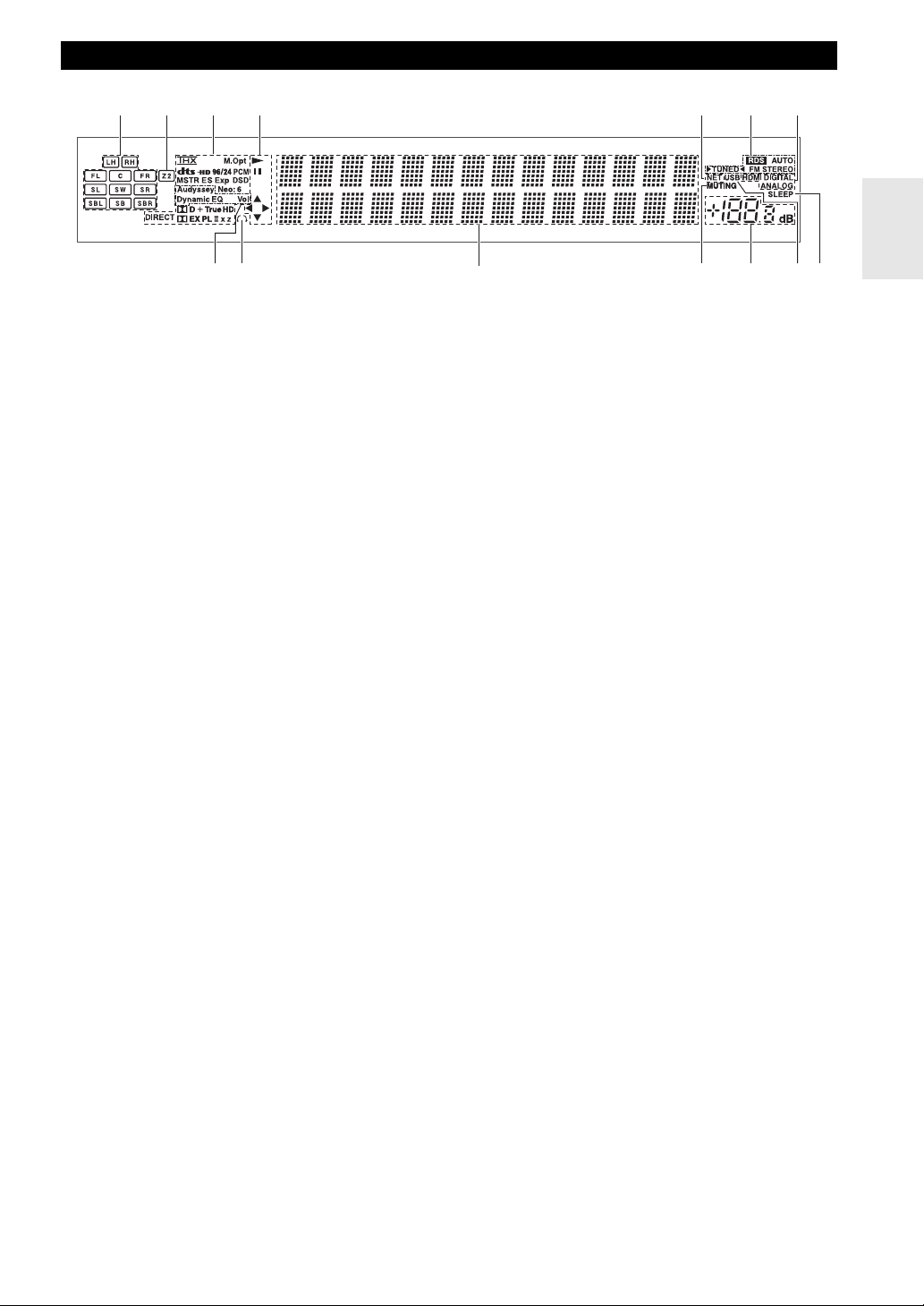
For detailed information, see the pages in parentheses.
a Speaker/channel indicators
b Z2 (Zone 2) indicator (60)
c Listening mode and format indicators (33, 58)
d 1, 3 and cursor indicators (22)
e NET indicator (24, 56)
f Tuning indicators
RDS indicator (excluding North American models)
(28)
AUTO indicator (27)
TUNED indicator (27)
FM STEREO indicator (27)
g Audio input indicators
h Audyssey indicator (30, 48)
Dynamic EQ indicator (48)
Dynamic Vol indicator (49)
i Headphone indicator (40)
j Message area
k MUTING indicator (40)
l Volume level (22)
m USB indicator (23, 24)
n SLEEP indicator (39, 52)
Display
cb dfea g
i
j
klm
n
h
10
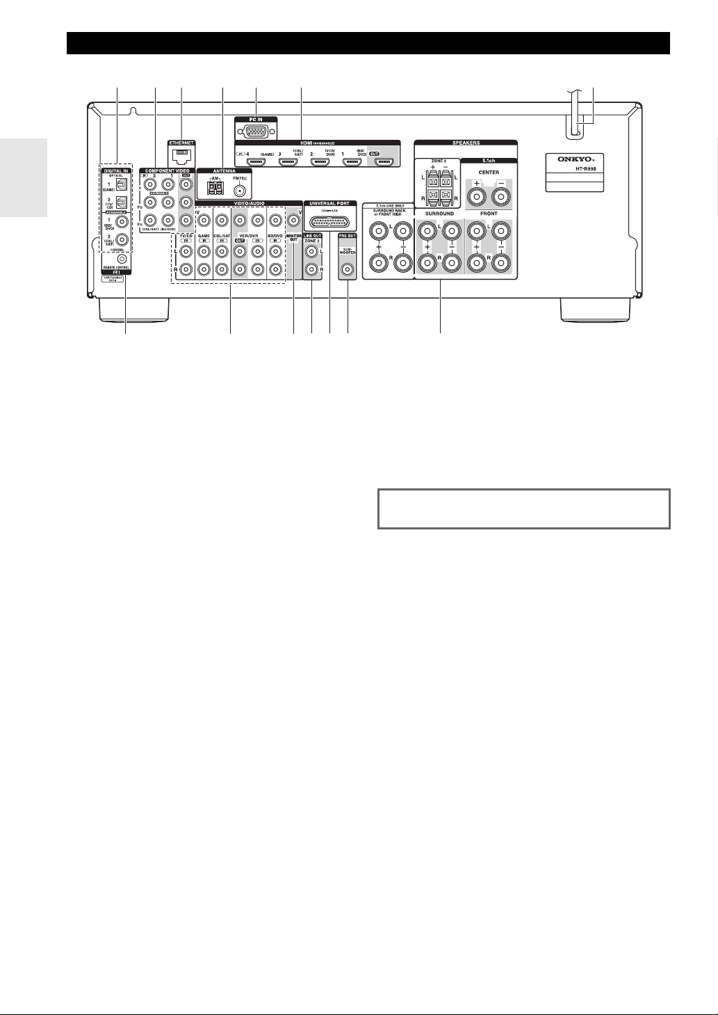
En
a DIGITAL IN COAXIAL and OPTICAL jacks
b COMPONENT VIDEO IN and OUT jacks
c ETHERNET port
d FM ANTENNA jack and AM ANTENNA terminal
e PC IN jack
f HDMI IN and OUT jacks
g Power cord
h u REMOTE CONTROL jack
i Composite video and analog audio jacks
(BD/DVD IN, VCR/DVR IN and OUT, CBL/SAT
IN, GAME IN, TV/CD IN)
j MONITOR OUT V jack
k ZONE 2 LINE OUT jacks
l UNIVERSAL PORT jack
m SUBWOOFER PRE OUT jack
n SPEAKERS terminals
(CENTER, FRONT, SURROUND, SURROUND
BACK or FRONT HIGH, ZONE 2)
Rear Panel
a b
f
g
e
h
i
jklm
n
c d
See “Connecting the AV Receiver” for connection
(➔ pages 12 to 20).
11
En
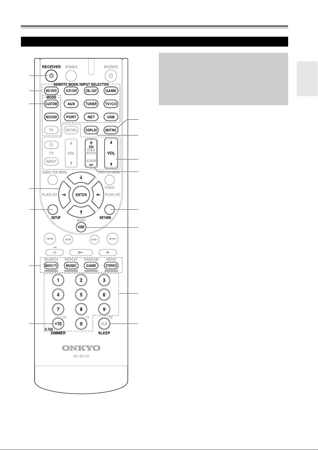
Remote Controller
For detailed information, see the pages in parentheses.
a 8RECEIVER button (21)
b REMOTE MODE/INPUT SELECTOR buttons
(22)
c Arrow q/w/e/r and ENTER buttons
d SETUP button (41)
e Listening Mode buttons (33)
f DIMMER button (39)
g MUTING button (40)
h DISPLAY button (40)
i VOL q/w button (22)
j RETURN button
k HOME button (39, 57)
l SLEEP button (39)
■ Controlling the tuner
To control the AV receiver’s tuner, press TUNER (or
RECEIVER).
You can select AM or FM by pressing TUNER
repeatedly.
a Arrow q/w buttons (27)
b D.TUN button (28)
c DISPLAY button
d CH +/– button (28)
e Number buttons (28)
*1
To control component, you must first enter remote control
code.
See “Entering Remote Control Codes” for more details
(
➔ page 64).
*2
These buttons can be used when not in receiver mode, and
when a REMOTE MODE other than receiver mode is
selected.
Controlling the AV Receiver
i
j
k
c
d
l
f
b
d
a
c
b
a
g
h
e
e
*1
*2
*2
To control the AV receiver, press RECEIVER to
select Receiver mode.
You can also use the remote controller to control
Onkyo Blu-ray Disc/DVD player, CD player, and
other components.
See “Entering Remote Control Codes” for more
details (➔ page 64).
12
En
Connections
Connecting the AV Receiver
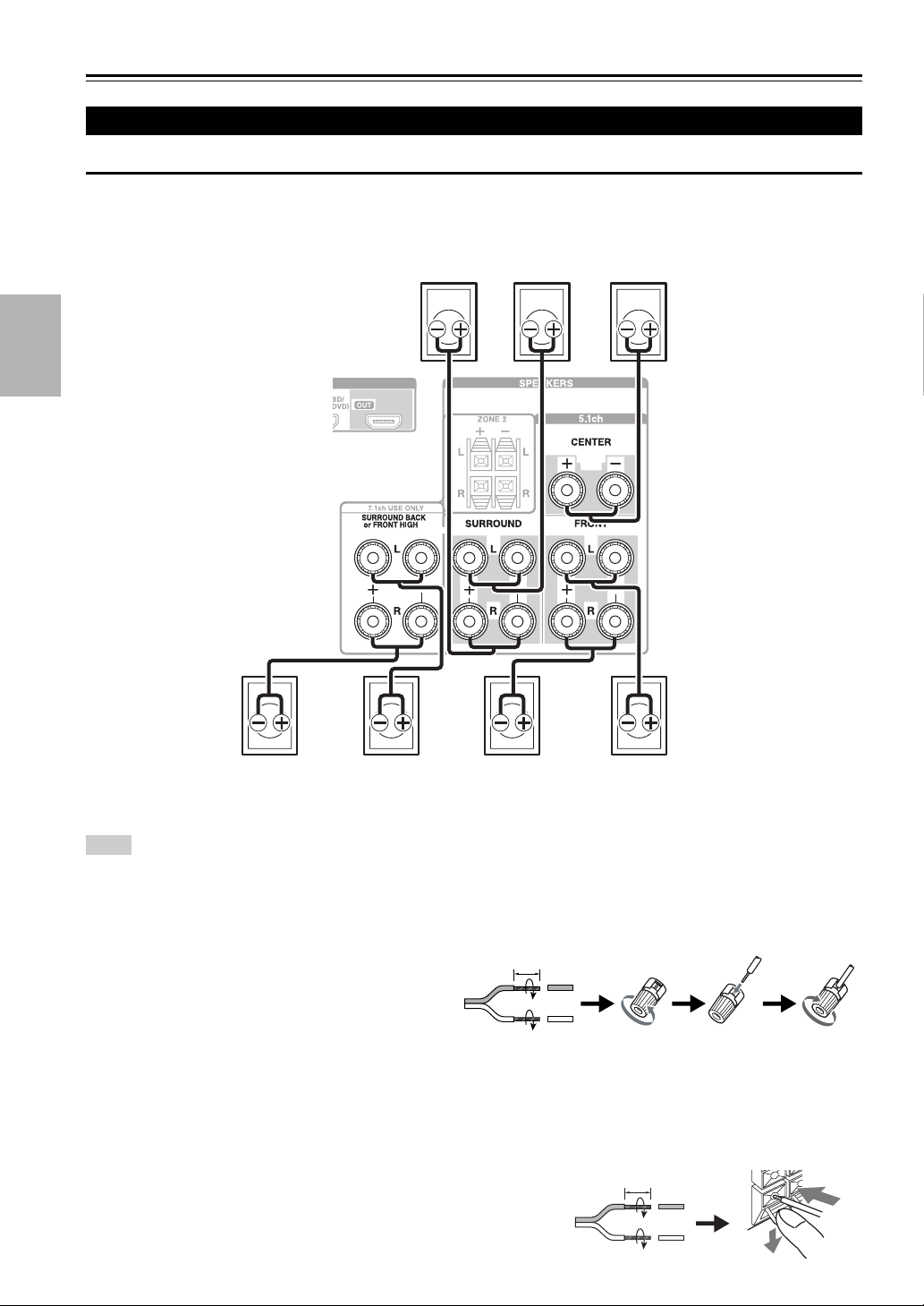
Connecting the Speaker Cables
The following illustration shows which speaker should be connected to each pair of terminals. If you’re using only one
surround back speaker, connect it to the SURROUND BACK or FRONT HIGH L terminals.
Tip
• You can specify whether surround back or front high speakers are connected in the “Speaker Configuration” menu (➔ page 44) or
during Audyssey 2EQ
®
Room Correction and Speaker Setup (➔ page 30).
• The speakers you can connect will differ depending on the speaker system that you have.
■ Screw-type speaker terminals
Strip 1/2" to 5/8" (12 to 15 mm) of insulation from
the ends of the speaker cables, and twist the bare
wires tightly, as shown. (Supplied speaker cables are
already stripped.)
■ Banana Plugs (North American models)
• If you are using banana plugs, tighten the speaker terminal before inserting the banana plug.
• Do not insert the speaker code directly into the center hole of the speaker terminal.
■ Push-type speaker terminals
Strip 3/8" to 1/2" (10 to 12 mm) of insulation from the ends of the
speaker cables, and twist the bare wires tightly, as shown. (Supplied
speaker cables are already stripped.)
Connecting Your Speakers
Surround back/
Front high
right
Surround
left
Surround
right
Center
Front leftFront right
Surround back/
Front high
left
1/2" to 5/8" (12 to 15 mm)
3/8" to 1/2" (10 to 12 mm)
13
En
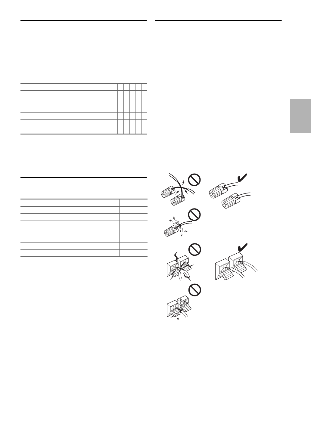
Speaker Configuration
The following table indicates the channels you should use
depending on the number of speakers that you have.
No matter how many speakers you use, a powered
subwoofer is recommended for a really powerful and solid
bass.
To get the best from your surround sound system, you
need to set the speaker settings automatically
(➔ page 30) or manually (➔ page 43).
*1
If you’re using only one surround back speaker, connect it to
the SURROUND BACK or FRONT HIGH L terminals.
*2
Front high and surround back speakers cannot be used at the
same time.
Connecting the Speaker Cables
The speaker terminals are color-coded for identification
purpose.
Speaker Connection Precautions
Read the following before connecting your speakers:
• You can connect speakers with an impedance of between
6 and 16 ohms. If you use speakers with a lower
impedance, and use the amplifier at high volume levels
for a long period of time, the built-in amp protection
circuit may be activated.
• Disconnect the power cord from the wall outlet before
making any connections.
• Read the instructions supplied with your speakers.
• Pay close attention to speaker wiring polarity. In other
words, connect positive (+) terminals only to positive (+)
terminals, and negative (–) terminals only to negative (–)
terminals. If you get them the wrong way around, the
sound will be out of phase and will sound unnatural.
• Unnecessarily long, or very thin speaker cables may
affect the sound quality and should be avoided.
• Be careful not to short the positive and negative wires.
Doing so may damage the AV receiver.
• Make sure the metal core of the wire does not have
contact with the AV receiver’s rear panel. Doing so may
damage the AV receiver.
Number of channels 2345677
Front speakers ✔✔✔✔✔✔✔
Center speaker ✔✔✔✔✔
Surround speakers ✔✔✔✔✔
Surround back speaker
*1*2
✔
Surround back speakers
*2
✔
Front high speakers
*2
✔
Speaker Color
Front left, Zone 2 left White
Front right, Zone 2 right Red
Center Green
Surround left Blue
Surround right Gray
Surround back left, Front high left Brown
Surround back right, Front high right Tan
14
En
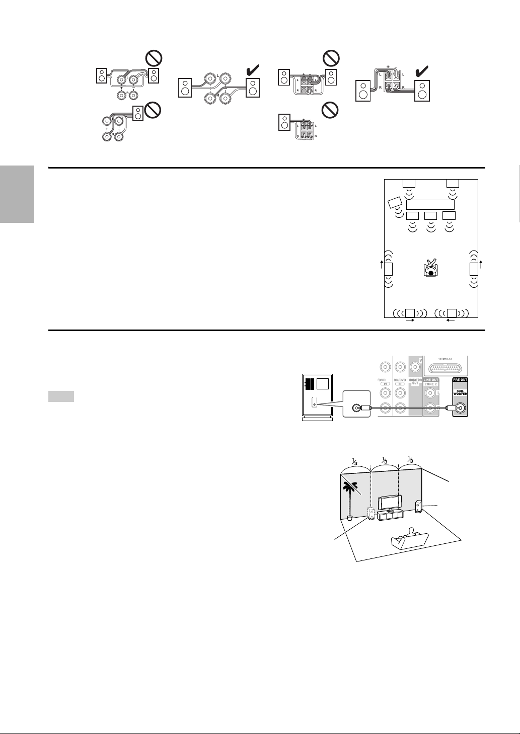
• Don’t connect more than one cable to each speaker terminal. Doing so may damage the AV receiver.
• Don’t connect one speaker to several terminals.
Using Dipole Speakers
You can use dipole speakers for the surround and surround back speakers. Dipole
speakers output the same sound in two directions.
Dipole speakers typically have an arrow printed on them to indicate how they should be
positioned. The surround dipole speakers (A) should be positioned so that their arrows
point toward the TV/screen, while the surround back dipole speakers (B) should be
positioned so that their arrows point toward each other, as shown.
Using a Powered Subwoofer
To find the best position for your subwoofer, while playing a
movie or some music with good bass, experiment by placing
your subwoofer at various positions within the room, and
choose the one that provides the most satisfying results.
Tip
• If your subwoofer is unpowered and you’re using an external
amplifier, connect the subwoofer pre out jack to an input on the
amplifier.
BB
AA
TV/screen
LINE INPUT
LINE INPUT
Powered subwoofer
Corner
position
1/3 of wall
position
15
En
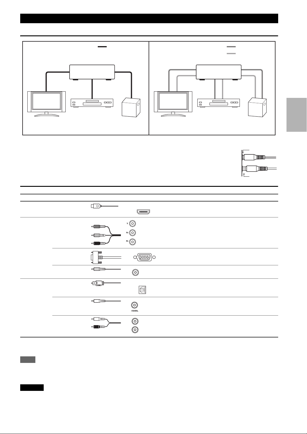
Connecting AV components
• Before making any AV connections, read the manuals supplied with your AV components.
• Don’t connect the power cord until you’ve completed and double-checked all AV connections.
• Push plugs in all the way to make good connections (loose connections can cause noise or
malfunctions).
• To prevent interference, keep audio and video cables away from power cords and speaker cables.
AV Cables and Jacks
*
Available sampling rate for PCM input signal (stereo/mono) is 32/44.1/48/88.2/96 kHz. In case of an HDMI connection,
176.4/192 kHz is also available.
Note
• The AV receiver does not support SCART plugs.
• The AV receiver’s optical digital jacks have shutter-type covers that open when an optical plug is inserted and close when it’s removed.
Push plugs in all the way.
Caution
• To prevent shutter damage, hold the optical plug straight when inserting and removing.
About AV Connections
Signal Cable Jack Description
Video and
Audio
HDMI HDMI connections can carry digital video and audio.
Video Component video Component video separates the luminance (Y) and color
difference signals (P
B, PR), providing the best picture
quality (some TV manufacturers label their component
video sockets slightly differently).
Analog RGB This is a conventional analog interface to connect a PC and
a display device (also called D-Sub or D-subminiature).
Composite video Composite video is commonly used on TVs, VCRs, and
other video equipment.
Audio Optical digital
audio
Optical digital connections allow you to enjoy digital
sound such as PCM
*
, Dolby Digital or DTS. The audio
quality is the same as coaxial.
Coaxial digital
audio
Coaxial digital connections allow you to enjoy digital
sound such as PCM
*
, Dolby Digital or DTS. The audio
quality is the same as optical.
Analog audio
(RCA)
Analog audio connections (RCA) carry analog audio.
HDMI cable Other cables
: Video & Audio
: Video
: Audio
Game console
Blu-ray Disc/
DVD player
TV, projector, etc.
Game console
Blu-ray Disc/
DVD player
TV, projector, etc.
AV receiverAV receiver
Right!
Wrong!
HDMI
Y
P
B
PR
Green
Blue
Red
V
Yellow
OPTICAL
Orange
L
R
White
Red
16
En
Connect your components to the appropriate jacks. The default input assignments are shown below.
✔: Assignment can be changed (➔ page 42).
See also:
• “Connection Tips and Video Signal Path” (➔ page 79)
• “About HDMI” (➔ page 81)
• “Using an RIHD-compatible TV, Player, or Recorder” (➔ page 82)
■ Audio Return Channel (ARC) function
Audio Return Channel (ARC) function enables an HDMI capable TV to send the audio stream to the HDMI OUT of the
AV receiver.
• This function can be used when:
– your TV is ARC capable, and
–the TV/CD input selector is selected, and
–“HDMI Control (RIHD)” is set to “On”(➔ page 54), and
–“Audio Return Channel” is set to “Auto” (➔ page 55).
Tip
• To listen to audio received by the HDMI IN jacks through your TV’s speakers:
– Set the “HDMI Control (RIHD)” setting to “On” (➔ page 54) for an p-compatible TV.
– Set the “Audio TV Out” setting to “On” (➔ page 55) when the TV is not compatible with p, or the “HDMI Control
(RIHD)” setting to “Off”.
– Set your Blu-ray Disc/DVD player’s HDMI audio output setting to PCM.
– To listen to TV audio through the AV receiver, see “Connecting Your Components” (➔ page 17).
Note
• When listening to an HDMI component through the AV receiver, set the HDMI component so that its video can be seen on the TV
screen (on the TV, select the input of the HDMI component connected to the AV receiver). If the TV power is off or the TV is set to
another input source, this may result in no sound from the AV receiver or the sound may be cut off.
•As the “Audio TV Out” setting is set to “On” (➔ page 55) to hear from your TV speakers, the sound will also be output from the AV
receiver’s speakers if you adjust the volume of the AV receiver. Similarly, as the
“HDMI Control (RIHD)” setting is set to “On”
(➔ page 54) to hear from the speakers of an p-compatible TV, the AV receiver’s speakers will produce sound if you adjust
the volume of the AV receiver, while the TV speakers will be muted. To stop the AV receiver’s speakers from producing sound, you
can either change the settings on the AV receiver or on the TV, or turn down the volume of the AV receiver.
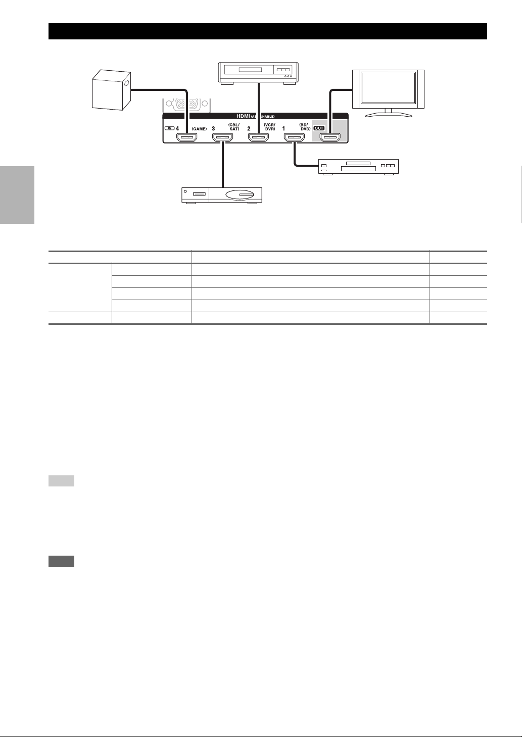
Connecting Components with HDMI
Jack Components Assignable
Input HDMI IN 1 Blu-ray Disc/DVD player ✔
HDMI IN 2 VCR or DVD recorder/Digital Video Recorder ✔
HDMI IN 3 Satellite/cable set-top box, etc. ✔
HDMI IN 4 Game console ✔
Output HDMI OUT TV, projector, etc.
Game console
VCR or DVD recorder/Digital Video Recorder
TV, projector,
etc.
Satellite/cable set-top box, etc.
Blu-ray Disc/DVD player
17
En
Connect your components to the appropriate jacks. The default input assignments are shown below. See “Connection
Tips and Video Signal Path” for more information (➔ page 79).
✔: Assignment can be changed (➔ page 43).
Note
*1
When USB input is selected, you can input video signals from the AUX INPUT VIDEO jack. Video signals input from AUX
INPUT VIDEO will be output from the MONITOR OUT V jack.
*2
Do not connect the AV receiver’s USB port to a USB port on your computer. Music on your computer cannot be played through the
AV receiver in this way.
*3
Connect a turntable (MM) that has a phono preamp built-in. If your turntable (MM) doesn’t have it, you’ll need a commercially
available phono preamp.
If your turntable has a moving coil (MC) type cartridge, you’ll need a commercially available MC head amp or MC transformer as
well as a phono preamp. See your turntable’s manual for details.
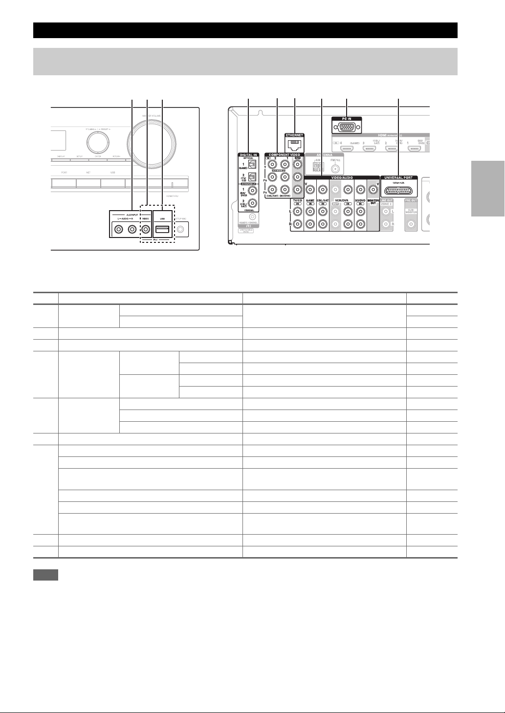
Connecting Your Components
The on-screen menus appear only on a TV that is connected to the HDMI OUT. If your TV is connected to other
video outputs, use the AV receiver’s display when changing settings.
No. Jack/Port Components Assignable
A
AUX INPUT AUDIO L/R Camcorder, etc
VIDEO
B
USB, AUX INPUT VIDEO
*1
iPod/iPhone (video playback)
C
USB
*2
iPod/iPhone, MP3 player, USB flash drive
D
DIGITAL IN OPTICAL 1 (GAME) Game console ✔
2 (TV/CD) TV, CD player ✔
COAXIAL 1 (BD/DVD) Blu-ray Disc/DVD player ✔
2 (CBL/SAT) Satellite/cable set-top box, RI dock, etc. ✔
E
COMPONENT
VIDEO
IN 1 (BD/DVD) Blu-ray Disc/DVD player, RI dock ✔
IN 2 (CBL/SAT) Satellite/cable set-top box, RI dock, etc. ✔
OUT TV, projector, etc.
F
ETHERNET Router
G
MONITOR OUT TV, projector, etc.
BD/DVD IN Blu-ray Disc/DVD player
VCR/DVR IN VCR or DVD recorder/digital video recorder, RI
dock
CBL/SAT IN Satellite/cable set-top box, etc.
GAME IN Game console, RI dock
TV/CD IN TV, CD player, cassette tape deck, MD, CD-R,
Turntable
*3
, RI dock
H
PC IN
*4
Personal computer ✔
I
UNIVERSAL PORT Universal port option dock (UP-A1 etc.)
A CB
EDGHF I

18
En
*4
When you connect your personal computer to PC IN and select the corresponding input selector, the video of the personal computer
is output from the HDMI outputs. However, if you have assigned the HDMI inputs to the same input selector, the AV receiver will
output signals received from the HDMI inputs instead of signals from PC IN. To have the signals output from PC IN, select
“-----” for the corresponding input selector in the “HDMI Input” setting (➔ page 42).
• With connection D, you can enjoy Dolby Digital and DTS. (To record or listen the audio in Zone 2 as well, use D and
G.)
• With connection G, you can listen to and record audio from external components while you are in Zone 2.
• With connection
G, if your Blu-ray Disc/DVD player has both the main stereo and multichannel outputs, be sure to
connect to the main stereo.
■ How to record a video source
With the connections described above, you cannot record the videos through the AV receiver. See “Recording” about
connections for video recording (➔ page 40).
19
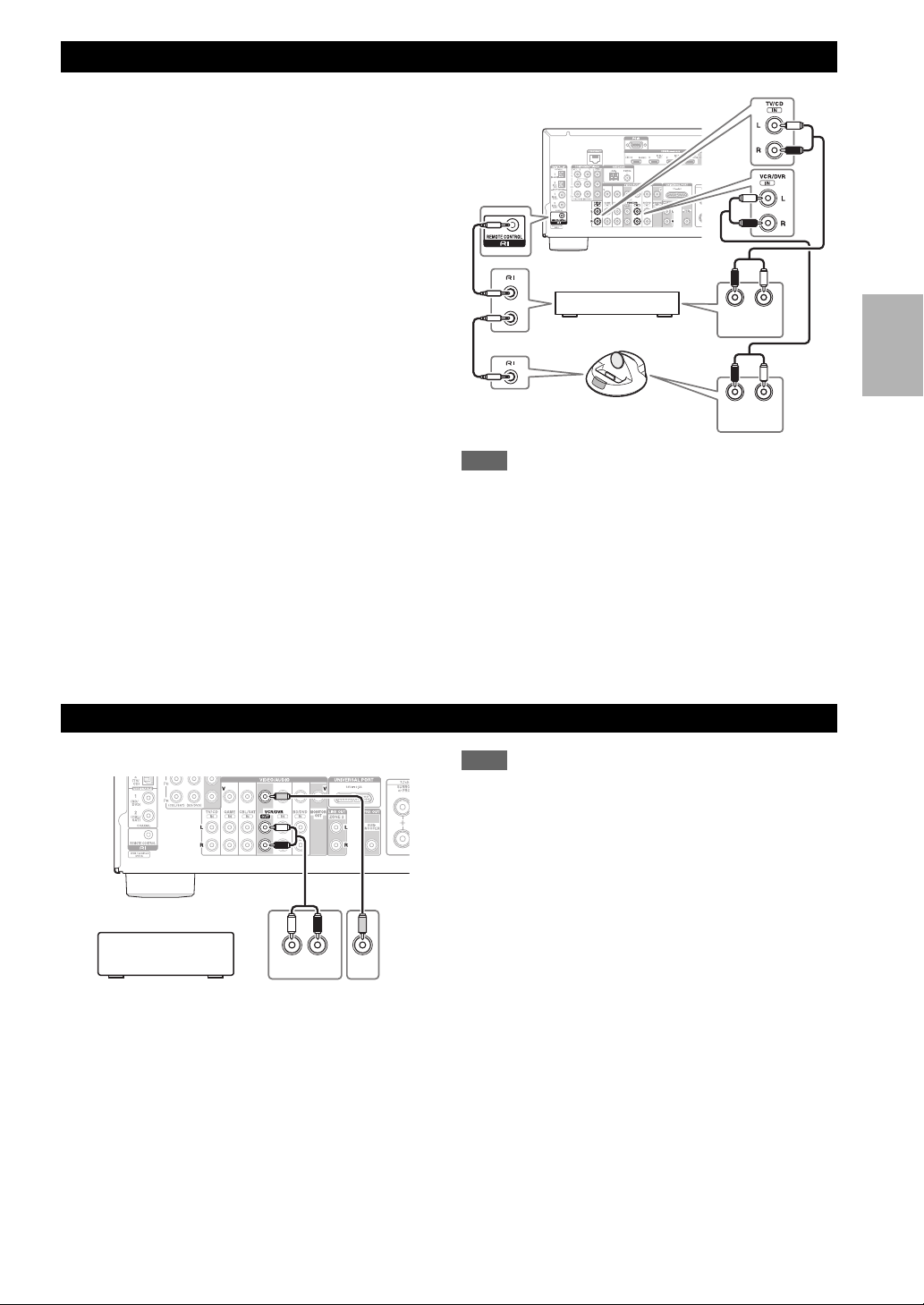
En
With u (Remote Interactive), you can use the following
special functions:
■ System On/Auto Power On
When you start playback on a component connected via
u while the AV receiver is on Standby, the AV
receiver will automatically turn on and select that
component as the input source.
■ Direct Change
When playback is started on a component connected via
u, the AV receiver automatically selects that
component as the input source.
■ Remote Control
You can use the AV receiver’s remote controller to
control your other u-capable Onkyo components,
pointing the remote controller at the AV receiver’s
remote control sensor instead of the component. You
must enter the appropriate remote control code first
(➔ page 65).
Note
•Use only u cables for u connections. u cables are supplied
with Onkyo components.
• Some components have two u jacks. You can connect either
one to the AV receiver. The other jack is for connecting
additional u-capable components.
• Connect only Onkyo components to u jacks. Connecting other
manufacturer’s components may cause a malfunction.
• Some components may not support all u functions. Refer to
the manuals supplied with your Onkyo components.
• While Zone 2 is on, the System On/Auto Power On and Direct
Change u functions do not work.
See “Recording” for details on recording (➔ page 40).
Note
• The AV receiver must be turned on for recording. Recording is
not possible while it’s in standby mode.
• If you want to record directly from your TV or playback VCR to
the recording VCR without going through the AV receiver,
connect the TV/VCR’s audio and video outputs directly to the
recording VCR’s audio and video inputs. See the manuals
supplied with your TV and VCR for details.
• Video signals connected to composite video inputs can be
recorded only via composite video outputs. For example, if your
TV/VCR is connected to a composite video input, the recording
VCR must be connected to a composite video output.
• The surround sound and DSP listening modes cannot be
recorded.
• Copy-protected Blu-ray Discs and DVDs cannot be recorded.
• Sources connected to a digital input cannot be recorded. Only
analog inputs can be recorded.
• DTS signals will be recorded as noise, so don’t attempt analog
recording of DTS CDs or LDs.
Connecting Onkyo u Components
1
Make sure that each Onkyo component is
connected with an analog audio cable (connection
G in the hookup examples) (➔ page 17).
2
Make the u connection (see the illustration).
3
If you’re using an RI Dock, or cassette tape deck,
change the Input Display (➔ page 40).
LR
ANALOG
AUDIO OUT
LR
ANALOG
AUDIO OUT
e.g., CD player
RI Dock
Connecting a Recording Component
AUDI O
IN
LR
VIDEO
IN
VCR, DVD recorder,
cassette tape deck,
CDR, MD recorder, etc.
20
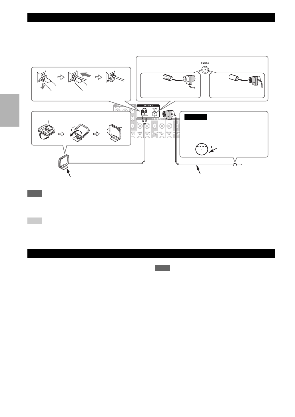
En
This section explains how to connect the supplied indoor FM antenna and AM loop antenna.
The AV receiver won’t pick up any radio signals without any antenna connected, so you must connect the antenna to use
the tuner.
Note
• Once your AV receiver is ready for use, you’ll need to tune into a radio station and position the antenna to achieve the best possible
reception.
• Keep the AM loop antenna as far away as possible from your AV receiver, TV, speaker cables, and power cords.
Tip
• If you cannot achieve good reception with the supplied indoor FM antenna, try a commercially available outdoor FM antenna instead.
• If you cannot achieve good reception with the supplied indoor AM loop antenna, try using it with a commercially available outdoor
AM antenna.
Note
• Before connecting the power cord, connect all of your
speakers and AV components.
• Turning on the AV receiver may cause a momentary power
surge that might interfere with other electrical equipment on the
same circuit. If this is a problem, plug the AV receiver into a
different branch circuit.
Connecting the Antennas
Connecting the Power Cord
Thumbtacks, etc.
Insert the plug fully
into the jack.
Insert the plug fully
into the jack.
North American models European models
Push. Insert wire. Release.
Assembling the AM loop antenna
Indoor FM antenna (supplied)
AM loop antenna (supplied)
Caution
• Be careful not to injure yourself
when using thumbtacks.
1
Plug the power cord into an AC wall outlet.
21
En
Turning On & Basic Operations
Turning On/Off the AV Receiver
Tip
• For details on power management settings, see “Auto Standby” (➔ page 55).
Turning On
1
Press 8ON/STANDBY on the front panel.
or
Press RECEIVER followed by 8RECEIVER on the remote controller.
The AV receiver comes on, the display lights.
Turning Off
1
Press 8ON/STANDBY on the front panel.
or
Press RECEIVER followed by 8RECEIVER on the remote controller.
The AV receiver will enter standby mode. To prevent any loud surprises when you turn on the AV receiver, always
turn down the volume before you turn it off.
8RECEIVER
RECEIVER
8ON/STANDBY
22
En
Playback
You can determine the language used for the onscreen
setup menus. See “Language” in the “OSD Setup”
(➔ page 54).
■ Operating with the remote controller
■ Operating on the AV receiver
See “Controlling Other Components” about the operation
of other components (➔ page 64).
The on-screen menus appear only on a TV that is
connected to the HDMI OUT. If your TV is connected
to other video outputs, use the AV receiver’s display
when changing settings.
This section describes the procedure for using the
remote controller unless otherwise specified.
Selecting the Language for the
Onscreen Setup Menus
Playing the Connected Component
1
Press RECEIVER followed by INPUT
SELECTOR.
2
Start playback on the source component.
See also:
• “Playing an iPod/iPhone via USB” (➔ page 23)
• “Playing a USB Device” (➔ page 24)
• “Listening to Internet Radio” (➔ page 24)
• “Playing Music Files on a Server” (➔ page 26)
• “Remote Playback” (➔ page 26)
• “Listening to AM/FM Radio” (➔ page 27)
• “iPod/iPhone Playback via Onkyo Dock”
(➔ page 61)
• “Controlling Other Components” (➔ page 64)
3
To adjust the volume, use VOL q/w.
4
Select a listening mode and enjoy!
See also:
• “Using the Listening Modes” (➔ page 33)
• “Audyssey” (➔ page 48)
1
Use the input selector buttons to select the input
source.
2
Start playback on the source component.
3
To adjust the volume, use the MASTER VOLUME
control.
4
Select a listening mode and enjoy!
Controlling Contents of USB or
Network Devices
a
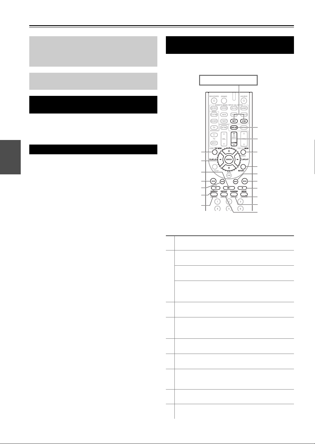
TOP MENU
This button displays the top menu for each media or service.
b
q/w and ENTER
These buttons navigate through the menus.
e/r
This button cycles through pages.
PLAYLIST e/r
In Standard Mode (iPod/iPhone), this button selects
playlists.
c
1
This button starts playback.
d
7
This button selects the beginning of the current song.
Pressing this button twice selects the previous song.
e
5
This button fast-reverses the current song.
f
3
This button pauses playback.
g
SEARCH
You can toggle between the playback screen and the list
screen during playback.
h
DISPLAY
This button switches between song informations.
i
ALBUM +/–
In Standard Mode (iPod/iPhone), this button selects albums.
d
k
j
m
b
a
c
e
f
g
l
n
o
q
h
i
p
Press USB or NET first.
23
En
Note
• The buttons you can use will differ depending on the devices and
media used for playback.
This section describes icons that appear on the display
during media playback.
This section explains how to play music/video files on the
iPod/iPhone.
Compatible iPod/iPhone models
Made for:
iPod touch (1st, 2nd, 3rd and 4th generation), iPod classic,
iPod with video, iPod nano (1st, 2nd, 3rd, 4th, 5th and 6th
generation), iPhone 4, iPhone 3GS, iPhone 3G, iPhone
Note
• Do not disconnect the USB device or USB cable that comes with
iPod/iPhone to the USB port at the front of the AV receiver,
while the message “Connecting...” appears on the display.
• If you connect an iPod or iPhone to the USB port on this device,
no sound will be output from the headphones jack.
j
MENU
This button returns to top menu of the Internet Radio
service.
k
RETURN
This button returns to the previous menu.
l
4
This button fast-forwards the current song.
m
6
This button selects the next song.
n
2
This button stops playback.
o
MODE
You can switch between Standard Mode and Extended
Mode during iPod/iPhone playback.
p
RANDOM
This button performs random playback.
q
REPEAT
Press this button repeatedly to cycle through the repeat
modes.
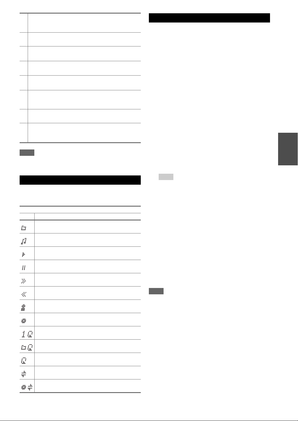
Understanding Icons on the Display
Displayed Icons
Icon Description
Folder
Track
Playback
Pause
Fast Forward
Fast Reverse
Artist
Album
Repeat One Track
Repeat Folder (USB Device)
Repeat
Shuffle
Shuffle Album (iPod/iPhone)
Playing an iPod/iPhone via USB
1
Press USB to select the “USB” input.
2
Connect the USB cable that comes with the
iPod/iPhone to the USB port on the front of the AV
receiver.
While reading the contents of your iPod/iPhone, the
message “Connecting...” appears on the display.
The USB indicator lights. It will flash if the AV
receiver cannot read the iPod/iPhone.
3
Press MODE repeatedly to switch to Extended
Mode (Music) or Extended Mode (Video).
A list of your iPod/iPhone model’s contents appears.
To open a folder, use q/w to select it, and then press
ENTER.
Tip
• With the default settings, the iPod/iPhone is operated in
Standard Mode.
• Pressing MODE repeatedly switches back to Standard
Mode.
• When you disconnect the iPod/iPhone, the AV receiver
stores the mode. This means that if you disconnect when in
Extended Mode (Music), the AV receiver will start in
Extended Mode (Music) the next time you connect the
iPod/iPhone.
• You can also use q/w, ENTER and TUNING MODE
buttons on the front panel. TUNING MODE allows you to
switch modes.
• When connecting your iPod/iPhone with a USB cable, we
recommend you use an official USB cable from Apple Inc.
4
Use q/w to select a music/video file, and press
ENTER or 1 to start playback.

24
En
Extended Mode (Music) control
The music content information is displayed (lists are
displayed), and you can control the music content while
looking at the screen.
Top screen list:
Playlists, Artists, Albums, Genres, Songs, Composers,
Shuffle Songs, Now Playing.
Extended Mode (Video) control
The video content information is displayed (lists are
displayed), and you can control the video content while
looking at the screen.
Top screen list:
Movies, Music Videos, TV Shows, Video Podcasts,
Rentals.
Note
• To view the video contents of your iPod/iPhone, connect it to the
USB port and AUX INPUT VIDEO jack on the AV receiver’s
front panel, using the official Apple Composite AV Cable.
• Depending on your iPod/iPhone model and generation, the
displayed items may vary and the support for Extended Mode
(Video) is not guaranteed.
Standard Mode control
The content information is not displayed, but can be
operated using the iPod/iPhone or the remote controller
(USB).
Note
• The following iPod models are not supported in Standard Mode.
(They can only be controlled in Extended Mode).
– iPod with video
– iPod nano (1st generation)
This section explains how to play music files from a USB
device (e.g., USB flash drives and MP3 players).
See also:
• “Network/USB Features” (➔ page 73).
Note
• Do not disconnect the USB device or USB cable that comes with
iPod/iPhone to the USB port at the front of the AV receiver,
while the message “Connecting...” appears on the display.
You can select Internet radio stations by connecting to the
AV receiver from your computer and selecting stations in
your web browser.
Internet radio URLs in the following formats are
supported: PLS, M3U, and podcast (RSS). However,
depending on the type of data or audio format used by the
Internet radio station, you may not be able to listen to
some stations.
Note
• Services available may vary depending on the region. See the
separate instructions for more information.
Listening to vTuner Internet Radio
This unit includes the full vTuner Internet Radio Service
at no additional charge. Once you have connected your
unit to the Internet you can select vTuner Internet Radio to
search for and play Internet radio stations and podcasts at
any time. To enhance your Internet radio experience, the
http://onkyo.vtuner.com/ portal is available to you as an
easy way to browse to find stations, set up/organize your
favorites, add your own stations, get help, etc. After the
first time you try vTuner Internet Radio on your unit you
can use the MAC Address of your unit to create a member
login account (email address and password) on the
http://onkyo.vtuner.com/ portal. To verify your MAC
Address, please see “Network” (➔ page 56).
Playing a USB Device
1
Press USB to select the “USB” input.
2
Plug your USB device into the AV receiver’s USB
port.
The USB indicator lights. It will flash if the AV
receiver cannot read the USB device.
3
Press ENTER.
A list of the device’s contents appears. To open a
folder, use q/w to select it, and then press ENTER.
4
Use q/w to select a music file, and press ENTER or
1 to start playback.
Listening to Internet Radio
You need to connect the AV receiver to your home
network (➔ page 73).
1
Press NET.
The “NET” screen appears, and the NET indicator
lights. If it flashes, verify that the Ethernet cable is
firmly connected to the AV receiver.
2
Use q/w/e/r to select “vTuner Internet Radio”
and then press ENTER.

25
En
Listening to Other Internet Radio
To listen to other internet radio stations, insert the
following step after step 1 in the “Listening to vTuner
Internet Radio” section.
Registering My Favorites
*1
You can add the currently playing song or station to the
“My Favorites”. You can save up to 40 Internet radio
stations.
Once you’ve added a station to the list, simply select it in
the “My Favorites” menu, and then press ENTER to start
playback.
*1
From the search results you can save the stations and songs
but cannot listen to them directly.
■ Top menu of Internet Radio
` Create new station:
Add a favorite station or Internet radio to the My
Favorites.
` Rename this station:
You can rename the stations and songs saved in “My
Favorites” list.
` Delete from My Favorites:
You can delete the stations and songs saved in “My
Favorites” list.
3
Use q/w to select a program and then press
ENTER.
Playback starts.
Press MENU to enable selection from the following
menu items.
` Stations like this:
Stations like the one currently being played
back are displayed.
` Add to My Favorites:
Adds a station to My Favorites list.
Press TOP MENU to go to the top menu of the
Internet Radio services.
Tip
• By pressing SEARCH, you can toggle between the
playback screen and the radio list screen.
1
On your computer, start your web browser and
enter the AV receiver’s IP address in the browser’s
Internet address (URL) field.
The browser connects to the AV receiver (WEB
Setup Menu).
Note
• The AV receiver’s IP address is shown on “IP Address”
(➔ page 56).
• If you’re using DHCP, your router may not always allocate
the same IP address to the AV receiver, so if you find that
you can’t connect to the AV receiver, recheck the AV
receiver’s IP address on the “Network” screen.
2
Click on the “My Favorites” tab.
3
Enter the preset name and Internet address
(URL).
4
Click “Save” to save the Internet radio station.
5
The Internet radio station is then added to “My
Favorites”.
Greate Artist
My Music
My Favorite
0 : 11
1
Press MENU with the station selected or while a
song is playing.
2
Use q/w to select “Add to My Favorites”, and press
ENTER.
3
Use q/w/e/r to select “OK”, and then press
ENTER.
Tip
• If you choose to rename the station, see “Name Edit”
(
➔ page 50).
26
En
This section explains how to play music files on a
computer or media server through the AV receiver (Server
Playback).
Windows Media Player 11 Setup
This section explains how to configure Windows Media
Player 11 so that the AV receiver can play the music files
stored on your computer.
Remote Playback means you can play the music files
stored on a media server or personal computer with the
AV receiver by operating the controller device in the
home network.
Windows Media Player 12 Setup
This section explains how to configure Windows Media
Player 12 so that the AV receiver can play the music files
stored on your personal computer.
Playing Music Files on a Server
You need to connect the AV receiver to your home
network (➔ page 73).
1
Start your computer or media server.
2
Press NET.
The “NET” screen appears. The NET indicator
lights. If it flashes, confirm the network connection.
3
Use q/w/e/r to select “dlna”, and press ENTER.
Tip
• To go back to the previous screen, press RETURN.
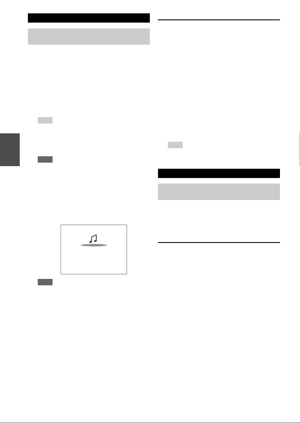
4
Use q/w to select a server, and then press ENTER.
The menu is displayed according to the server
functions.
Note
• The search function does not work with media servers
which do not support this function.
• Photos and movies stored on a media server cannot be
accessed from the AV receiver.
• Depending on the sharing settings in the media server, the
AV receiver may not able to access the content. See the
instruction manual of the media server.
5
Use q/w to select an item, and then press ENTER
or 1 to start playback.
Note
• Depending on the media server, 5/4/3 may not
work.
• If the message “No Item.” appears, this means that no
information can be retrieved from the server. In this case,
check your server, network, and AV receiver connections.
Artist name
My favorite song 1
My favorite album
0 : 11
1
Start Windows Media Player 11.
2
On the “Library” menu, select “Media Sharing”.
The “Media Sharing” dialog box appears.
3
Select the “Share my media” check box, and then
click “OK”.
4
Select the AV receiver in the list, and then click
“Allow”.
5
Click “OK” to close the dialog box.
This completes the Windows Media Player 11
configuration.
You can now play the music files in your Windows
Media Player 11 library through the AV receiver.
Tip
• Windows Media Player 11 can be downloaded for free
from the Microsoft web site.
Remote Playback
You need to connect the AV receiver to your home
network (➔ page 73).
1
Start Windows Media Player 12.
2
On the “Stream” menu, select “Turn on media
streaming”.
A dialog box appears.
3
Move your cursor and click on “Turn on media
streaming”.
A list of media server appears. Wording may vary
slightly depending on the network location.
4
Select the product in the list, and then click
“Allowed”.
5
Click “OK” to close the dialog box.
This completes the Windows Media Player 12
configuration.
You can now play the music files in your Windows
Media Player 12 library.
27
En
Using Remote Playback
Using the Tuner
With the built-in tuner you can enjoy AM and FM radio
stations. You can store your favorite stations as presets for
quick selection.
You can also change the frequency steps (➔ page 54).
Tuning into Radio Stations
■ Auto tuning mode
■ Manual tuning mode
In manual tuning mode, FM stations will be in mono.
1
Start Windows Media Player 12.
To enable remote playback, you must first configure
Windows Media Player 12.
2
Press NET.
The “NET” screen appears. The NET indicator
lights. If it flashes, verify the network connection.
3
Use q/w/e/r to select “dlna”, and press ENTER.
A list of media server appears.
Note
• Remote playback cannot be used while the music files of
another media server are being played. You must stop their
playback first.
4
On Windows Media Player 12, right-click on a
music file.
The right-click menu appears. For selecting another
media server, select the desired media server from the
“Other Libraries” menu on Windows Media Player
12.
5
Select the AV receiver from the right-click menu.
The “Play to” window appears and playback on the
product starts. Operations during remote playback
can be made from the “Play to” window of Windows
7 on your personal computer. During remote
playback, operations (such as Playback, Pause, Fast
Forward, Fast Rewind, Previous, Next, Repeat,
Random) cannot be made.
6
Adjusting the Volume.
You can adjust the volume by adjusting the volume
bar in the “Remote playback” window. The default
maximum volume level is 82 (0dB). If you wish to
change this, enter the value from the Web Setup in
your browser.
The volume value of the remote window and the
volume value of the AV receiver may not always
match.
Adjustments you make to the volume in the AV
receiver will not be reflected in the “Remote
playback” window.
Listening to AM/FM Radio
This section describes the procedure using the
buttons on the front panel unless otherwise specified.
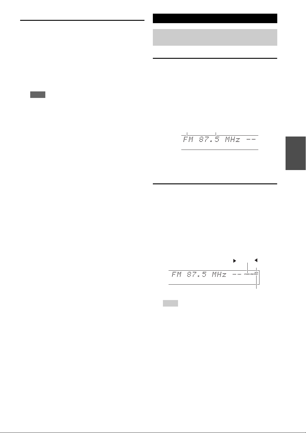
1
Press TUNER to select either “AM” or “FM”.
In this example, FM has been selected.
Each time you press TUNER, the radio band changes
between AM and FM.
(Actual display depends on the country.)
1
Press TUNING MODE so that the AUTO indicator
lights on the display.
2
Press TUNING q/w.
Searching stops when a station is found.
When tuned into a station, the TUNED indicator
lights. When tuned into a stereo FM station, the FM
STEREO indicator lights on the display, as shown.
Tip
• Tuning into weak FM stereo stations
If the signal from a stereo FM station is weak, it may be
impossible to get good reception. In this case, switch to
manual tuning mode and listen to the station in mono.
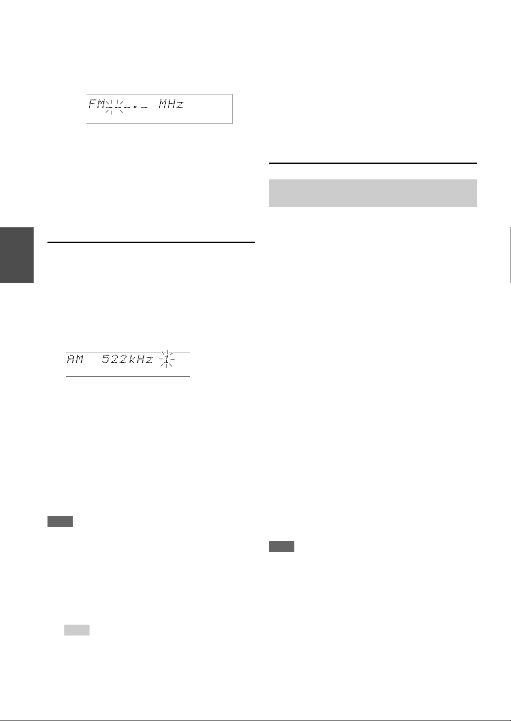
1
Press TUNING MODE so that the AUTO indicator
goes off on the display.
2
Press and hold TUNING q/w.
The frequency stops changing when you release the
button.
Press the buttons repeatedly to change the frequency
one step at a time.
Band Frequency
TUNED
FM
S
TERE
O
AUTO
28
En
■ Tuning into stations by frequency
You can tune into AM and FM stations directly by
entering the appropriate frequency.
Presetting AM/FM Stations
You can store a combination of up to 40 of your favorite
AM/FM radio stations as presets.
Note
• You can name your radio presets for easy identification
(➔ page 50). Its name is displayed instead of the band and
frequency.
■ Selecting Presets
■ Deleting Presets
Using RDS (excluding North American
models)
When tuned into an RDS station, the RDS indicator lights.
When the station is broadcasting text information, the text
can be displayed.
■ What is RDS?
RDS stands for Radio Data System and is a method of
transmitting data in FM radio signals. It was developed by
the European Broadcasting Union (EBU) and is available
in most European countries. Many FM stations use it these
days. In addition to displaying text information, RDS can
also help you find radio stations by type (e.g., news, sport,
rock, etc.).
The AV receiver supports four types of RDS information:
PS (Program Service)
When tuned to an RDS station that’s broadcasting PS
information, the station’s name will be displayed. Pressing
DISPLAY will display the frequency for 3 seconds.
RT (Radio Text)
When tuned to an RDS station that’s broadcasting text
information, the text will be shown on the display as
described in the next section.
PTY (Program Type)
This allows you to search for RDS radio stations by type
(➔ page 29).
TP (Traffic Program)
This allows you to search for RDS radio stations that
broadcast traffic information (➔ page 29).
Note
• In some cases, the text characters displayed on the AV receiver
may not be identical to those broadcast by the radio station. Also,
unexpected characters may be displayed when unsupported
characters are received. This is not a malfunction.
• If the signal from an RDS station is weak, RDS data may be
displayed intermittently or not at all.
1
On the remote controller, press TUNER repeatedly
to select “AM” or “FM”, followed by D.TUN.
(Actual display depends on the country.)
2
Within 8 seconds, use the number buttons to enter
the frequency of the radio station.
For example, to tune to 87.5 (FM), press 8, 7, 5.
If you have entered the wrong number, you can retry
after 8 seconds.
1
Tune into the AM/FM station that you want to
store as a preset.
See the previous section.
2
Press MEMORY.
The preset number flashes.
(Actual display depends on the country.)
3
While the preset number is flashing (about 8
seconds), use PRESET e/r to select a preset from
1 through 40.
4
Press MEMORY again to store the station or
channel.
The station or channel is stored and the preset number
stops flashing.
Repeat this procedure for all of your favorite AM/FM
radio stations.
1
To select a preset, use PRESET e/r on the AV
receiver, or the remote controller’s CH +/–.
Tip
• You can also use the remote controller’s number buttons to
select a preset directly.
1
Select the preset that you want to delete.
See the previous section.
2
While holding down MEMORY, press TUNING
MODE.
The preset is deleted and its number disappears from
the display.
RDS works only in areas where RDS broadcasts are
available.

29
En
■ Displaying Radio Text (RT)
■ Finding Stations by Type (PTY)
You can search for radio stations by type.
■ Listening to Traffic News (TP)
You can search for stations that broadcast traffic news.
RDS program types (PTY)
1
Press RT/PTY/TP once.
The RT information scrolls across the display.
Note
• The message “Waiting” may appear while the AV receiver
waits for the RT information.
• If the message “No Text Data” appears on the display, no
RT information is available.
1
Press RT/PTY/TP twice.
The current program type appears on the display.
2
Use PRESET e/r to select the type of program
you want.
See the table shown later in this chapter.
3
To start the search, press ENTER.
The AV receiver searches until it finds a station of the
type you specified, at which point it stops briefly
before continuing with the search.
4
When a station you want to listen to is found, press
ENTER.
If no stations are found, the message “Not Found”
appears.
1
Press RT/PTY/TP three times.
If the current radio station is broadcasting TP (Traffic
Program), “[TP]” will appear on the display, and
traffic news will be heard as and when it’s broadcast.
If “TP” without square brackets appears, this means
that the station is not broadcasting TP.
2
To locate a station that is broadcasting TP, press
ENTER.
The AV receiver searches until it finds a station that’s
broadcasting TP.
If no stations are found, the message “Not Found”
appears.
Type Display
None None
News reports News
Current affairs Affairs
Information Info
Sport Sport
Education Educate
Drama Drama
Culture Culture
Science and technology Science
Varied Varied
Pop music Pop M
Rock music Rock M
Middle of the road music Easy M
Light classics Light M
Serious classics Classics
Other music Other M
Weather Weather
Finance Finance
Children’s programmes Children
Social affairs Social
Religion Religion
Phone in Phone In
Travel Travel
Leisure Leisure
Jazz music Jazz
Country music Country
National music Nation M
Oldies music Oldies
Folk music Folk M
Documentary Document
Alarm test TEST
Alarm Alarm!
30
En
Using Basic Functions
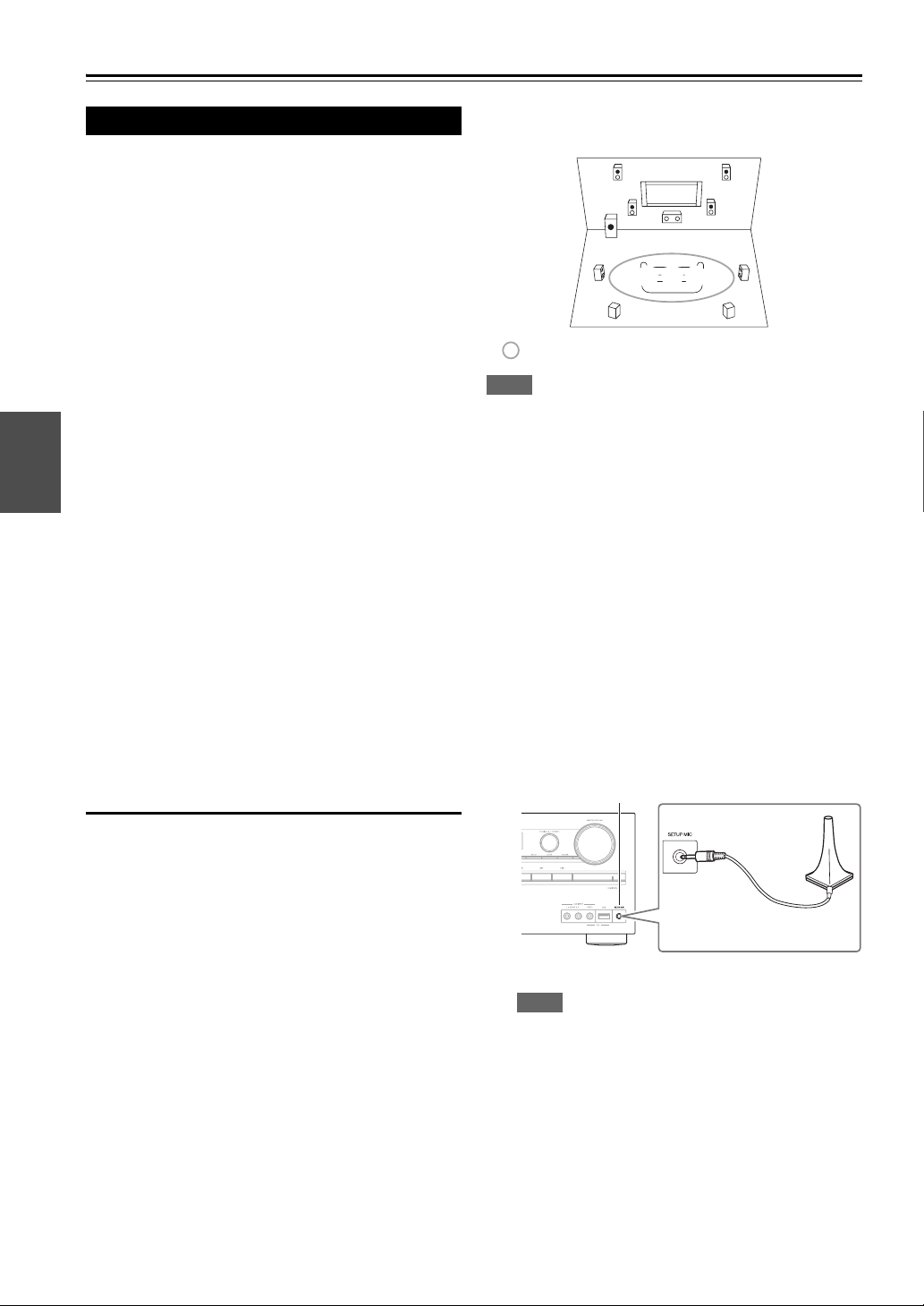
With the supplied calibrated microphone,
Audyssey 2EQ
®
automatically determines the number of
speakers connected, their size for purposes of bass
management, optimum crossover frequencies to the
subwoofer (if present), and distances from the primary
listening position.
Audyssey 2EQ then removes the distortion caused by
room acoustics by capturing room acoustical problems
over the listening area in both the frequency and time
domain. The result is clear, well-balanced sound for
everyone. Audyssey 2EQ can be used with
Audyssey Dynamic EQ
®
and
Audyssey Dynamic Volume
®
(➔ pages 48, 49).
Before using this function, connect and position all of
your speakers.
Audyssey 2EQ offers two ways of measuring: the
“Audyssey Quick Start” and “Audyssey 2EQ Full
Calibration”.
•“Audyssey Quick Start” uses the measurement from
one position to perform the speaker setting only.
•“Audyssey 2EQ Full Calibration” uses the
measurement from three positions to correct room
response in addition to the speaker setting.
The more positions are used in measuring, the better the
listening environment will become. We recommend using
a measurement from three positions to create the best
listening environment.
The Quick Start takes 2 minutes and Full Calibration takes
about 10 minutes.
Total measurement time varies depending on the number
of speakers.
Measurement procedure
To create a listening environment in your home theater
that all listeners will enjoy, Audyssey 2EQ takes
measurements at up to three positions within the listening
area. Position the microphone at ear height of a seated
listener with the microphone tip pointed directly at the
ceiling using a tripod. Do not hold the microphone in your
hand during measurements as this will produce inaccurate
results.
a First measurement position
Also referred to as the Main Listening Position this
refers to the most central position where one would
normally sit within the listening environment.
Audyssey 2EQ uses the measurements from this
position to calculate speaker distance, level, polarity,
and the optimum crossover value for the subwoofer.
b Second measurement position
The right side of the listening area.
c Third measurement position
The left side of the listening area.
The distances from position a to b and a to c must be
at least 1 meter (3.3 ft).
Note
• Make the room as quiet as possible. Background noise and Radio
Frequency Interference (RFI) can disrupt the room
measurements. Close windows, televisions, radios, air
conditioners, fluorescent lights, home appliances, light dimmers,
or other devices. Turn off the cell phone (even if it is not in use)
or place it away from all audio electronics.
• The microphone picks up test tones played through each speaker
as Audyssey 2EQ Room Correction and Speaker Setup run.
• Audyssey 2EQ Room Correction and Speaker Setup cannot be
performed while a pair of headphones is connected.
Using the Automatic Speaker Setup
1
Turn on the AV receiver and the connected TV.
On the TV, select the input to which the AV receiver
is connected.
2
On the subwoofer, set the OUTPUT LEVEL
control to THX POSITION.
3
Set the speaker setup microphone at the Main
Listening Position a, and connect it to the SETUP
MIC jack.
The speaker setting menu appears.
Note
• The on-screen menus appear only on a TV that is
connected to the HDMI OUT. If your TV is
connected to other video outputs, use the AV
receiver’s display when changing settings.
TV
abc
: Listening area
a to c: Listening position
Speaker setup microphone
SETUP MIC jack
Loading...