


Stereo Cassette Tape Deck
K-501A
English
using Before
Instruction Manual


 STEREO CASSETTE TAPE DECK
CASSETTE LOADING MECHANISM
B C
CD DUBBING
STANDBY / ON |
DOLBY NR REV MODE |
ALBUM |
FADE |
STANDBY
K-501A
|
|
|
|
|
1/K-501A(hyo1)_E.65E |
1 |
10/17/01, 10:23 AM |
||
Connections
Operation
Information Other
Before using
Thank you for purchasing ...
Thank you for purchasing Onkyo K-501A Stereo Cassette Tape Deck.
Please read this manual thoroughly before making connections and plugging in the unit. Following the instructions in this manual will enable you to obtain optimum performance and listening enjoyment from your new K-501A.
Please retain this manual for future reference.
Main Features
•A compact, discrete component with155mm (6-1/8") wide
•Dolby* B NR and Dolby C NR systems that reduce tape background hiss
Declaration of Conformity
We, ONKYO EUROPE ELECTRONICS GmbH INDUSTRIESTRASSE 20 82110 GERMERING, GERMANY
declare in own responsibility, that the ONKYO product described in this instruction manual is in compliance with the corresponding technical standards such as EN60065, EN55013, EN55020 and EN61000-3-2, -3-3.
GERMERING, GERMANY
I. MORI
ONKYO EUROPE ELECTRONICS GmbH
•Dolby HX Pro system that expands the dynamic range in higher frequencies and constantly adjusts recording conditions
*Dolby noise reduction and HX Pro headroom extension manufactured under license from Dolby Laboratories Licensing Corporation. HX Pro originated by Bang and Olufsen.
“Dolby,” the double-D symbol and “HX Pro” are trademarks of Dolby Laboratories Licensing Corporation.
WARNING:
TO REDUCE THE RISK OF FIRE OR ELECTRIC SHOCK, DO NOT EXPOSE THIS APPLIANCE TO RAIN OR MOISTURE.
CAUTION:
TO REDUCE THE RISK OF ELECTRIC SHOCK, DO NOT REMOVE COVER (OR BACK). NO USER-SERVICEABLE PARTS INSIDE. REFER SERVICING TO QUALIFIED SERVICE PERSONNEL.
WARNING |
|
AVIS |
RISK OF ELECTRIC SHOCK |
|
RISQUE DE CHOC ELECTRIQUE |
DO NOT OPEN |
|
NE PAS OUVRIR |
|
|
|
The lightning flash with arrowhead symbol, within an equilateral triangle, is intended to alert the user to the presence of uninsulated “dangerous voltage” within the product’s enclosure that may
be of sufficient magnitude to constitute a risk of electric shock to persons.
The exclamation point within an equilateral triangle is intended to alert the user to the presence of important operating and maintenance
(servicing) instructions in the literature accompanying the appliance.
2

Important Safeguards
1.Read Instructions – All the safety and operating instructions should be read before the appliance is operated.
2.Retain Instructions – The safety and operating instructions should be retained for future reference.
3.Heed Warnings – All warnings on the appliance and in the operating instructions should be adhered to.
4.Follow Instructions – All operating and use instructions should be followed.
5.Water and Moisture – The appliance should not be used near water – for example, near a bathtub, washbowl, kitchen sink, laundry tub, in a wet basement, or near a swimming pool, and the like.
6.Carts and Stands – The appliance should be used only with a cart or stand that is recommended by the manufacturer.
6A. An appliance and cart combination should be moved with care. Quick stops, excessive force, and uneven surfaces may cause the appliance and cart combination to overturn.
PORTABLE CART WARNING
S3125A 
7.Wall or Ceiling Mounting – The appliance should be mounted to a wall or ceiling only as recommended by the manufacturer.
8.Ventilation – The appliance should be situated so that its location or position does not interfere with its proper ventilation. For example, the appliance should not be situated on a bed, sofa, rug, or similar surface that may block the ventilation openings; or if placed in a built-in installation, such as a bookcase or cabinet that may impede the flow of air through the ventilation openings, there should be at least 5 cm (2 in.) of free space behind the appliance.
9.Heat – The appliance should be situated away from heat sources such as radiators, heat registers, stoves, or other appliances (including amplifiers) that produce heat.
10.Power Sources – The appliance should be connected to a power supply only of the type
described in the operating instructions or as marked on the appliance.
11.Polarization – If the appliance is provided with a polarized plug having one blade wider than the other, please read the following information:
The polarization of the plug is a safety feature. The polarized plug will only fit the outlet one way. If the plug does not fit fully into the outlet, try reversing it. If there is still trouble, the user should seek the services of a qualified electrician. Under no circumstances should the user attempt to defeat the polarization of the plug.
12.Power-Cord Protection – Power-supply cords should be routed so that they are not likely to be walked on or pinched by items placed upon or against them, paying particular attention to the cords at plugs, convenience receptacles, and the point where they exit from the appliance.
13.Cleaning – The appliance should be cleaned only as recommended by the manufacturer.
14.Nonuse Periods – The power cord of the appliance should be unplugged from the outlet when left unused for a long period of time.
15.Object and Liquid Entry – Care should be taken so that objects do not fall and liquids are not spilled into the enclosure through openings.
16.Damage Requiring Service – The appliance should be serviced by qualified service personnel when:
A.The power-supply cord or the plug has been damaged; or
B.Objects have fallen or liquid has been spilled into the appliance; or
C.The appliance has been exposed to rain; or
D.The appliance does not appear to operate normally or exhibits a marked change in performance; or
E.The appliance has been dropped or the enclosure damaged.
17.Servicing – The user should not attempt to service the appliance beyond that described in the operating instructions. All other servicing should be referred to qualified service personnel.
18.Liquid Hazards – The appliance shall not be exposed to dripping or splashing and no objects filled with liquids, such as vases shall be placed on the appliance.
Using Before
Connections
Operations
Information Other
3

Precautions
1.Recording Copyright
Recording of copyrighted material for other than personal use is illegal without permission of the copyright holder.
2.Deck Location
•Do not use or leave in direct sunlight or in other places subject to high temperature and humidity. The unit should also not be left in potentially hot places such as near heating appliances. Excessive heat and moisture can lead to internal damage and serious malfunctions (this also applies to
cassette tapes). The recommended ambient temperature range is 5°C to 35°C.
•Avoid damp and dusty places and locations prone to vibrations.
•Be extremely careful with the recording/ playback heads. Clean and demagnetize them regularly, but under no circumstances should magnets or other metals be used anywhere near the heads.
•This unit is extremely sensitive to magnetic fields, so do not use near large speakers or other devices which generate magnetic fields.
•Hum may even be induced by magnetic flux leakage from the power transformer in certain amplifiers. Therefore, this unit should also be kept clear of the amplifier.
•Do not remove the cabinet case. If any of the internal parts are handled, there is a considerable danger of electric shock.
3.Cassettes to Avoid:
•Cassettes with poorly formed cases that rattle during rewind and fast forward.
•Low cost cassettes with no guide roller or pressure pad spring should never be used for stereo.
•C-120 cassettes because the tape and the coating are extremely thin, distortion levels are high. Also, even a slight stretching of the tape will make it susceptible to being caught up in the pinch roller and capstan.
•Endless tapes, if used for a long period of time, can overheat.
4.Care
|
From time to time you should wipe the front |
|
and rear panels and the cabinet with a soft |
|
cloth. For heavier dirt, dampen a soft cloth in |
|
a weak solution of mild detergent and water, |
|
wring it out dry, and wipe off the dirt. |
|
Following this, dry immediately with a clean |
|
cloth. Do not use rough material, thinners, |
|
alcohol or other chemical solvents or cloths |
|
since these could damage the finish or remove |
|
the panel lettering. |
5. |
Power |
|
WARNING |
4 |
BEFORE PLUGGING IN THE UNIT FOR THE FIRST |
TIME, READ THE FOLLOWING SECTION CAREFULLY. |
The voltage of the available power supply differs according to country or region. Be sure that the power supply voltage of the area where this unit will be used meets the required voltage (e.g., AC230V 50Hz or AC120V 60Hz) written on the rear panel.
For British Model
Replacement and mounting of an AC plug on the power supply cord of this unit should be performed only by qualified service personnel.
IMPORTANT:
The wires in the mains lead are coloured in accordance with the following code:
Blue: Neutral
Brown: Live
As the colours of the wires in the mains lead of this appliance may not correspond with the coloured markings identifying the terminals in your plug, proceed as follows:
The wire which is coloured BLUE must be connected to the terminal in the plug which is marked with the letter N or coloured BLACK.
The wire which is coloured BROWN must be connected to the terminal in the plug which is marked with the letter L or coloured RED.
IMPORTANT
A 5 ampere fuse is fitted in this plug. Should the fuse need to be replaced please ensure that the replacement fuse has a rating of 5 amperes and that it is approved by ASTA or BSI to BS 1362. Check for the ASTA mark or the BSI mark on the body of the fuse.
IF THE FITTED MOULDED PLUG IS UNSUITABLE FOR THE SOCKET OUTLET IN YOUR HOME THEN THE FUSE SHOULD BE REMOVED AND THE PLUG CUT OFF AND DISPOSED OF SAFELY. THERE IS A DANGER OF SEVERE ELECTRICAL SHOCK IF THE CUT OFF PLUG IS INSERTED INTO ANY 13 AMPERE SOCKET.
If in any doubt please consult a qualified electrician.
For Canadian model NOTE:
THIS CLASS B DIGITAL APPARATUS COMPLIES WITH CANADIAN ICES-003.
For models having a power cord with a polarized plug:
CAUTION: TO PREVENT ELECTRIC SHOCK, MATCH WIDE BLADE OF PLUG TO WIDE SLOT, FULLY INSERT.
Modele pour les Canadien REMARQUE:
CET APPAREIL NUMÉRIQUE DE LA CLASSE B EST CONFORME À LA NORME NMB-003 DU CANADA. Sur les modèles dont la fiche est polarisée: ATTENTION: POUR ÉVITER LES CHOCS ÉLECTRIQUES, INTRODUIRE LA LAME LA PLUS LARGE DE LA FICHE DANS LA BORNE CORRESPONDANTE DE LA PRISE ET POUSSER JUSQU’AU FOND.
1/K-501A(p02~05)_E.65E |
4 |
10/17/01, 10:22 AM |
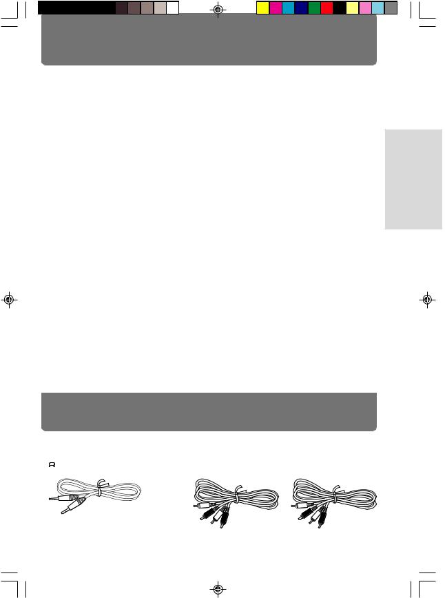
Table of contents |
|
Before Using |
|
Checking the supplied accessories ............................................... |
Below |
Connections |
|
Connecting to the ONKYO Separate Collection Series components .... 6 |
|
Connecting to other components ....................................................... |
7 |
Operation |
|
Playing a tape .................................................................................... |
9 |
Recording ........................................................................................ |
12 |
CD dubbing with ONKYO Separate Collection Series ........................ |
16 |
CD/MD/CDR Synchro Recording with ONKYO Separate |
|
Collection Series ............................................................................... |
20 |
Other Information |
|
Handling cassette tapes/Maintenance ............................................... |
22 |
Troubleshooting ............................................................................... |
23 |
Specifications ................................................................................... |
25 |
Index to parts and controls ............................................................... |
26 |
Checking the supplied accessories
Check that the following accessories are supplied with this unit.
• |
|
remote control cable × 1 |
• Audio connection cable × 2 |
|
|||
|
1/K-501A(p02~05)_E.65E |
5 |
10/17/01, 10:22 AM |
Using Before
Connections
Operations
Information Other
5
Connections
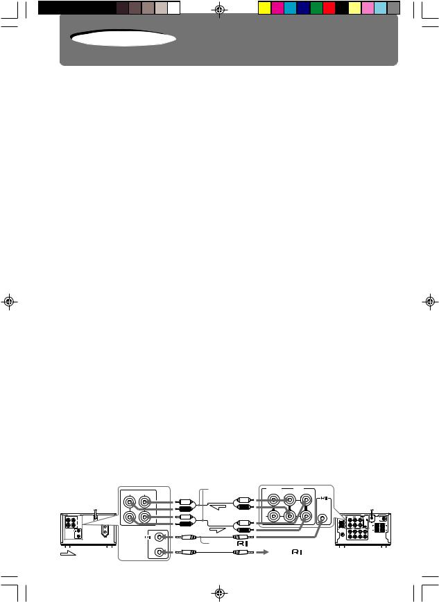
Connecting to the ONKYO Separate Collection Series components
This section introduces you to the other ONKYO Separate Collection Series system components and their convenient system functions. For the actual connecting instructions and detailed information, please refer to the Instruction Manual of the Tuner Amplifier R-801A.
The following ONKYO Separate Collection Series components are commercially available:
•C-701A ........ Compact Disc (CD) Player (Not available in U.S.A. and Canada)
•MD-101A ..... Minidisc (MD) Recorder (Not available in U.S.A., Canada and Europe)
•R-801A ......... TUNER AMPLIFIER (Not available in U.S.A. and Canada)
•CDR-201A .... Compact Disc (CD) Recorder (Not available in U.S.A. and Canada)
Note that the available components may vary according to the area.
Combination use of the unit with the above system components enables you to operate the following convenient functions:
•Auto Power On
–You can turn on the amplifier by pressing the STANDBY/ON button on one of the system components.
–You can turn on all the system components at the same time by pressing the STANDBY/ON button on the amplifier.
You can turn off each component not in use independently afterwards.
•Direct Change
Press the following button on the component you want to operate to switch the amplifier’s input selector automatically to that component:
–The play button on the K-501A.
•Remote Control Operation
All the system components can be operated using the remote controller supplied with the R-801A.
•Program Timer
You can operate timer playback and recording using the R-801A (refer to the Instruction Manual of the R-801A).
•Sleep Timer
You can fall asleep to a music/radio program using the timer (refer to the Instruction Manual of the R-801A).
•CD Dubbing
Simple CD dubbing with this unit is possible with the pressing of a single button (see page 16).
•CD/MD/CDR Synchro Recording
When using this unit to record a tape from the CD player, MD recorder or CD recorder, you can start recording automatically (while the unit is in recording standby) at the same time as you start playing a CD, MD or CDR (see page 20).
•MD/CDR Synchro Recording from this unit
When using the MD recorder or CD recorder to record a MD or CD from this unit, you can start recording automatically at the same time as you start playing a tape.
Connecting the unit to R-801A
Supplied audio
|
R |
L |
connection cable |
CD/DVD |
OUT |
TAPE |
|
|
|
|
|
IN |
IN |
|
|
|
|||||
|
|
|
|
|
|
|
|
|||
|
K-501A |
INPUT |
|
|
L |
|
REMOTE |
R-801A |
|
|
|
|
|
|
|
|
|
|
|
|
|
|
|
|
|
|
|
|
CONTROL |
|
|
|
|
|
OUTPUT |
|
|
R |
|
ANTENNA |
CD/DVD |
PRE OUT |
|
R L |
AC OUTLET |
|
|
|
|
|
|
SUBWOOFER |
||
|
INPUT |
|
|
|
|
|
L |
|
|
|
|
|
|
|
|
|
|
|
|
R |
L |
|
|
|
|
|
|
|
AM |
|
|
|
|
OUTPUT |
|
|
|
|
|
R |
|
|
|
|
|
|
|
|
|
|
|
MD |
CDR/PC SPEAKERS |
|
|
|
|
|
|
|
|
FM 75 L |
|
CAUTION: |
|
|
|
|
|
|
|
|
|
|
SPEAKER R |
L |
|
|
|
|
|
|
|
|
|
IMPEDANCE |
|
|
|
|
|
|
|
|
|
|
4 OHMS MIN. |
|
|
|
|
Supplied |
|
|
|
R |
|
/ SPEAKER |
|
|
|
CONTROL |
remote control cable |
|
|
|
||||
|
|
REMOTE |
|
|
|
|
|
|
|
|
6 |
: Signal flow |
|
|
|
To the |
connector |
|
|
|
|
|
|
|
|
on the other ONKYO component |
|
|||||
|
|
|
|
|
|
|||||
1/K-501A(p06~21)_E.65E |
6 |
|
|
|
10/17/01, 10:16 AM |
|
|
|
||
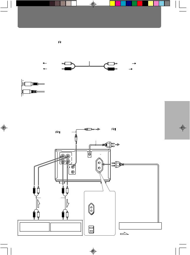
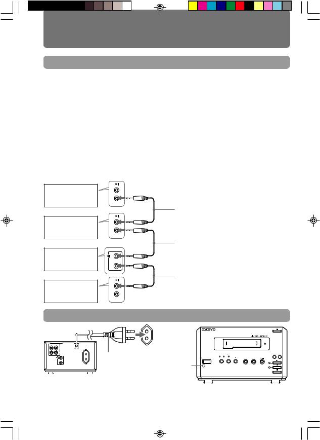
Connecting to other components
Before connecting
• Do not connect the AC power cord (mains lead) until you have completed all the other
connections including the |
|
connections on the next page. |
|
||
|
•On each pair of connectors, a red connector (marked R) corresponds to the right channel, and a white connector (marked L) to the left channel. Connect white plugs of audio connection cables to L connectors and connect red plugs of audio connection cables to R connectors .
|
|
Audio connection cable |
|
To L connectors |
(White) |
(White) |
To L connectors |
To R connectors |
(Red) |
(Red) |
To R connectors |
• Insert the plug securely. If the connection is incomplete, noise or malfunction may result.
 Improper connection
 Insert completely
•Bundling an audio connection cable with the power cord or speaker cord may degrade the sound quality.
•To use the unit with the other ONKYO Separate Collection Series components, follow the connection diagram in the R-801A instruction manual to connect the unit to the system.
Note:
The 230-240 V model is shown in the following illustrations.
Supplied |
remote |
To the |
connector on the other |
ONKYO component (See next page.) |
|||
control cable |
AC power cord (mains lead) |
||
|
|
||
To a wall outlet (the mains) (See next page.)
R |
L |
AC OUTLET |
|
|
|
AC 230-240V |
50 Hz |
|
INPUT |
UNSWITCHED |
|
|
100W MAX. |
|
|
|
OUTPUT |
|
|
|
REMOTE |
|
To the AC OUTLET |
|
CONTROL |
|
|
|
|
|
(UNSWITCHED) connector |
|
|
|
The AC power cord (mains lead) |
|
|
|
of the other component can be |
|
|
|
connected to this AC OUTLET |
|
|
|
connector. |
Red |
White |
Red |
White |
|
|
|
(to R) |
(to L) |
(to R) |
(to L) |
230-240 V, 50 Hz and |
Note on the AC OUTLET |
|
|
Supplied |
|
220-230 V, 50/60 Hz |
connector |
||
|
audio |
|
models |
The shape, number, or total |
||
|
connection |
|
Capacity is |
capacity of the AC outlets |
||
|
cable |
|
may differ depending on the |
|||
Red |
White |
Red |
White |
100 watts. |
area where the unit is |
|
|
purchased. |
|||||
(to R) |
(to L) |
(to R) |
(to L) |
|
||
120 V, 60 Hz models |
|
|||||
To the TAPE |
|
To the TAPE |
|
|
||
|
|
Capacity is |
Other component |
|||
OUTPUT (REC) jacks |
INPUT (PLAY) jacks |
|||||
|
||||||
|
Amplifier |
|
120 watts. |
: Signal flow |
||
|
|
|
||||
|
|
|
|
|
||
Using Before
Connections
Operation
Information Other
7
1/K-501A(p06~21)_E.65E |
7 |
10/17/01, 10:16 AM |
Connecting to other components (continued)
Connecting the 
 connectors
If you are using other ONKYO components equipped with 
 connectors, you can control these components using the amplifier’s remote controller.
Before connecting
•The amplifier must be connected in the 
 system hookups for
 control operations.
•Each component has two 
 connectors. There is no difference between these connectors.
•The components may be connected in any order.
•The hookups on the previous page are necessary independently of the 
 system hookups.
The illustration below is an example of a 
 hookup. With these hookups, you can operate the CD Synchro Recording; when recording a tape with this unit from the CD player, you can start recording automatically (while the unit is in recording standby) at the same time as you play the CD (see “CD Synchro Recording” on page 14).
For CD Synchro Recording, at least the unit, amplifier, and CD player must be connected with the 
 connectors.
Tuner
Amplifier
This unit (K-501A)
CD player
REMOTE CONTROL

 remote control cable (optional)
Supplied 
 remote control cable

 remote control cable (optional)
Note
An remote control cable equipped with a 1/8 in. (3.5mm) diameter miniature twoconductor phone plug is included with this unit and with every compact disc player and tuner that bears the
 mark.
mark.
Connecting the AC power cord (mains lead) to the wall outlet (the mains)
R |
L |
AC OUTLET |
|
|
AC 230-240V 50 Hz |
|
INPUT |
UNSWITCHED |
|
100W MAX. |
OUTPUT |
AC power cord |
|
|
REMOTE |
(mains lead) |
CONTROL |
|
The STANDBY indicator lights
Note
STEREO CASSETTE TAPE DECK
CASSETTE LOADING MECHANISM
|
B |
C |
|
|
|
|
|
CD DUBBING |
|
STANDBY / ON |
DOLBY NR REV MODE |
ALBUM |
FADE |
|
 STANDBY
K-501A
If you connect the AC power cord (mains lead) to the AC outlet of another component, the component’s AC power cord (mains lead) must be connected to the wall outlet (the mains) to supply power to the unit. If the component has a main power switch, it must be set to On.
8
1/K-501A(p06~21)_E.65E |
8 |
10/17/01, 10:16 AM |

Operation
Playing a tape
|
|
|
STANDBY/ ON |
|
|
|
|
|
TAPE IN indicator |
|
|
ACOUSTIC |
|
STANDBY/ON Cassette slot |
|
|
PRESENCE |
|
||
CDR/PC |
TAPE |
INPUT SELECTOR |
||||
|
|
|
CD/DVD |
MD |
FM |
AM |
STEREO CASSETTE TAPE DECK |
|
|
|
|
|
|
|
|
|
|
VO LUME |
|
|
|
|
|
TAPE REW |
|
UP |
TAPE FF |
|
|
|
|
MUTING |
|
|
CASSETTE LOADING MECHANISM |
|
|
DOWN |
|
||
|
|
|
|
|
||
|
|
|
SLEEP |
CLOCK |
TIMER |
ENTER |
B C |
|
|
MODE |
|
TAPE |
|
|
CD DUBBING |
|
|
|
|
|
STANDBY / ON DOLBY NR REV MODE |
ALBUM FADE |
|
REPEAT |
|
CD/DVD |
|
|
|
|
|
|
||
CLEAR |
MD |
STANDBY |
|
|
|
SCROLL |
CDR |
REPEAT |
|
|
|
K-501A |
|
|
|
|
|
1 |
2 |
3 |
4 |
|
REV MODE |
5 |
6 |
7 |
8 |
STANDBY |
9 |
10/0 |
--/--- |
(This remote controller is |
|
indicator |
DOLBY NR |
|
REMOTE CONTROLLER RC-466S |
supplied with R-801A.) |
|
1 Insert a recorded cassette in the cassette slot with the tape side facing to the left.
The unit turns on automatically if it is in standby. (The STANDBY indicator goes off, then the TAPE IN indicator lights.)
Note
The tape side of the cassette must face to the left.
Never insert it in any other direction.
STEREO CASSETTE TAPE DECK
CASSETTE LOADING MECHANISM
|
B |
C |
|
|
|
|
|
CD DUBBING |
|
STANDBY / ON |
DOLBY NR REV MODE |
ALBUM |
FADE |
|
 STANDBY
K-501A
2 Press DOLBY NR until the proper indicator of the Dolby NR mode lights, matching the mode the tape is recorded in.
The indicators light in the following order:
3 Press REV MODE (or REPEAT) to select the reverse mode.
Each press turns  (the REV MODE indicator) on or off.
REV MODE
•When  is lit (Auto reverse mode)
The unit plays both sides of the tape eight times and stops.
•When  goes off (One-way mode)
The unit will stop playing when the playing side of the tape reaches its end.
4 Press  to start playback (or
  to play the reverse side).
 or
or 
B(Dolby B NR)  C (Dolby C NR)
 The indicator goes off.

DOLBY NR
Note
No sound is reproduced while the unit is rotating the playing head for reverse side playback.
To stop playback
Press  . (Press this button to stop whatever the
tape operation is.)
To eject the cassette.
Press  .
.
(Continued on the next page)
1/K-501A(p06~21)_E.65E |
9 |
10/17/01, 10:16 AM |
Using Before
Connections
Operation
Information Other
9
 Loading...