


HT-S3910
Table of contents
 Loading...
Front Panel≫ Rear Panel≫ Remote≫
5.1-CHANNEL HOME THEATER SYSTEM
Instruction Manual
HT-S3910
En
Table of contents ≫
Connections ≫
- Connecting Speakers ≫
Playback ≫
Setup ≫
Troubleshooting ≫
Appendix ≫
Supplementary Information ≫
2
Front Panel≫ Rear Panel≫ Remote≫
Contents
≫
Connections
≫
Playback
≫
Setup
≫
What’s in the box 4
Additional Function (Firmware Update) 5
Update Information of the rmware 5
Operation of added new functions 5
Firmware Update Procedure 6
Part Names 8
Front Panel 8
Display 10
Rear Panel 11
Remote Controller 13
Speaker/Subwoofer 14
Connections
Connecting speakers 19
Speaker Installation 20
Speaker Connections and "Speaker Setup" Settings 25
Speaker combinations 28
Connecting the TV 29
To ARC TV 30
To Non-ARC TV 31
Connecting Playback Devices 32
Connecting an AV Component with HDMI Jack
Mounted 32
Connecting an Audio Component 33
Connecting an AV Component in a Separate Room
(ZONE B Connection) 34
Connecting a Pre-main Amplier (ZONE B) 34
Connecting Antennas 35
Connecting the Power Cord 36
Playback
AV Component Playback 38
Basic Operations 38
BLUETOOTH
®
Playback 39
Basic Operations 39
Listening To the AM/FM Radio 40
Tuning into a Radio Station 40
Presetting a Radio Station 42
Using RDS (European, Australian and Asian models) 44
ZONE B Playback 45
Playing Back 45
Convenience functions 47
Displaying Your Favorite Video on TV While Playing
Music 47
Adjusting the tone 48
Sleep Timer 49
Listening Mode 50
Selecting a Listening mode 50
3
Front Panel≫ Rear Panel≫ Remote≫
Contents
≫
Connections
≫
Playback
≫
Setup
≫
Speaker Layouts and Selectable Listening Modes 52
Listening Mode Effects 54
Input Formats and Selectable Listening Modes 58
Setup
Setup Menu 65
Menu list 65
Menu operations 67
1. Input/Output Assign 68
2. Speaker 71
3. Audio Adjust 74
4. Source 75
5. Hardware 77
6. Miscellaneous 80
Quick Menu 81
Menu operations 81
Initial Setup with Auto Start-up Wizard 83
Operations 83
Troubleshooting
When the unit is operating erratically 86
Troubleshooting 87
Appendix
About HDMI 93
General Specications 95

4
Front Panel≫ Rear Panel≫ Remote≫
Contents
≫
Connections
≫
Playback
≫
Setup
≫
What’s in the box
1. Main unit (HT-R398) (1)
2. Remote controller (RC-970R) (1), Batteries (AAA/R03) (2)
3. Indoor FM antenna (1)
4. AM loop antenna (1)
5. Front speaker (SKF-398) (2)
6. Center speaker (SKC-398) (1)
7. Surround speaker (SKR-398) (2)
8. Subwoofer (SKW-398) (1)
9. Speaker cable (10' (3 m)) (4)
10.
Speaker cable (26' (8 m)) (2)
11.
Non skid pad (20)
• When installing front speakers, center speaker, or surround speakers on a
rack, etc., apply non-skid pads at the bottom four corners of each speaker
to prevent them from sliding.
• Quick Start Guide (1)
* This document is an online instruction manual. It is not included as an
accessory.
• Connect speakers with an impedance of 4 Ω to 16 Ω.
• The power cord must be connected only after all other connections are
completed.
• We will not accept any responsibility for damage arising from the connection
with equipment manufactured by other companies.
• Specications and appearance are subject to change without prior notice.
1
7
8
9
bl
62
5
4
3
bk
5
Front Panel≫ Rear Panel≫ Remote≫
Contents
≫
Connections
≫
Playback
≫
Setup
≫
Additional Function (Firmware Update)
This unit is equipped with a function to update the rmware via USB port when the rmware update is announced after purchase. This enables various functions to be
added and operations to be improved.
Depending on the manufacturing timing of the product, the rmware may be switched to the updated one. In such a case, new functions may be added from the start.
For how to conrm the latest rmware contents and the rmware version of your product, see the following section.
Update Information of the rmware
For the latest rmware contents and the rmware version, visit our company’s website. If the rmware version of your product differs from the latest one, it is
recommended to update the rmware.
To conrm the rmware version of your product, press the button on the remote controller, and refer to "6. Miscellaneous" - "Firmware Update" - "Version" ( p80).
Operation of added new functions
If functions are added or changed from contents described in the Instruction Manual, see the following reference.
Supplementary Information ≫
❏ Firmware Update Procedure ( p6)

6
Front Panel≫ Rear Panel≫ Remote≫
Contents
≫
Connections
≫
Playback
≫
Setup
≫
Firmware Update Procedure
Approx. 30 minutes are required for updating. Existing settings are kept after
updating.
Disclaimer: The program and accompanying online documentation are furnished
to you for use at your own risk.
Our company will not be liable and you will have no remedy for damages for
any claim of any kind whatsoever concerning your use of the program or the
accompanying online documentation, regardless of legal theory, and whether
arising in tort or contract.
In no event will our company be liable to you or any third party for any special,
indirect, incidental, or consequential damages of any kind, including, but not
limited to, compensation, reimbursement or damages on account of the loss of
present or prospective prots, loss of data, or for any other reason whatsoever.
Updating the Firmware via USB
• While updating the rmware, do not do the following:
– Disconnecting and reconnecting cables, USB storage device or
headphones, or performing operations on the unit such as turning the
power off
• Prepare a 128 MB or larger USB storage device. The format of USB storage
devices supports FAT16 or FAT32 le system format.
– Media inserted into a USB card reader may not be used for this function.
– USB storage devices equipped with the security function are not supported.
– USB hubs and USB devices equipped with the hub function are not
supported. Do not connect these devices to the unit.
• Delete any data stored on the USB storage device.
• If "HDMI CEC" is set to "On", set it to "Off".
– Press . Next, select "5. Hardware" - "HDMI" and press ENTER, then
select "HDMI CEC" and select "Off".
* Depending on the USB storage device or its content, long time may be required
for loading, the content may not be loaded correctly, or power may not be supplied
correctly.
* Our company will not be liable whatsoever for any loss or damage of data, or storage
failure arising from the use of the USB storage device. Please note this in advance.
* The descriptions may differ from the actual on-screen displays, however, operations
and functions are the same.
Update
1. Connect the USB storage device to your PC.
2. Download the rmware le from the our company's website to your PC and
unzip.
Firmware les are named as below.
ONKAVR_.zip
Unzip the le on your PC. The number of unzipped les and folders varies
depending on the model.
3. Copy all unzipped les and folders to the root folder of the USB storage
device.
• Make sure to copy the unzipped les.
4. Connect the USB storage device to the POWER OUT port of this unit.
• If an AC adapter is supplied with the USB storage device, connect the AC
adapter, and use it with a household outlet.
• If the USB storage device has been partitioned, each section will be treated
as an independent device.
5. Press .
The Setup menu is displayed on the TV screen.
Setup
1. Input/Output Assign
4. Source
6. Miscellaneous
5. Hardware
2. Speaker
3. Audio Adjust
1. TV Out / OSD
4. Analog Audio Input
2. HDMI Input
3. Digital Audio Input

7
Front Panel≫ Rear Panel≫ Remote≫
Contents
≫
Connections
≫
Playback
≫
Setup
≫
6. Select "6. Miscellaneous" - "Firmware Update" - "Update via USB" with the
cursors in order, then press ENTER.
Setup
1. Input/Output Assign
4. Source
6. Miscellaneous
5. Hardware
2. Speaker
3. Audio Adjust
1. Tuner
4. Lock
2. Firmware Update
3. Initial Setup
• If "Firmware Update" is grayed out and cannot be selected, wait for a while
until it starts up.
7. Press ENTER with "Update" selected, and start update.
• During the update, the TV screen may go black depending on the program
to be updated. In such a case, check the progress on the display of the
unit. The TV screen will remain black until the update is completed and the
power is turned on again.
• During the update, do not turn the power off, or disconnect or reconnect the
USB storage device.
• When "Completed!" is displayed, the update is complete.
8. Disconnect the USB storage device from the unit.
9. Press ON/STANDBY on the main unit to turn the unit into standby mode.
The process is completed, and your rmware is updated to the latest version.
• Do not use on the remote controller.
If an Error Message is Displayed
If an error occurs, "Error! -" is displayed on the display of the unit. (""
represents an alphanumeric character.) Refer to the following descriptions and
check.
Error Code
• -70:
The USB storage device cannot be recognized, the rmware le is not present
in the root folder of the USB storage device, or the rmware le is for another
model. Check if the USB storage device or USB cable is securely inserted to
the POWER OUT port of the unit.
Connect the USB storage device to an external power source if it has its own
power supply.
• -51:
The rmware le is for another model, or the rmware le is corrupted. Retry
from the download of the rmware le.
• Others:
After removing the power plug once, insert it to the outlet, and then start the
operation from the beginning.

8
Contents
≫
Connections
≫
Playback
≫
Setup
≫
Front Panel≫ Rear Panel≫ Remote≫
Part Names
Front Panel
❏ For details, see ( p9)

9
Contents
≫
Connections
≫
Playback
≫
Setup
≫
Front Panel≫ Rear Panel≫ Remote≫
1. ON/STANDBY button
2. MUSIC OPTIMIZER button: Turns on/off the MUSIC OPTIMIZER function that
improves the quality of the compressed audio.
3. BLUETOOTH indicator: Lights up when this unit and a BLUETOOTH-enabled
device are connected.
4. DOLBY ATMOS indicator: Lights up when Dolby Atmos signals are reproduced
in appropriate listening mode.
5. Remote control sensor: Receives signals from the remote controller.
• The reception range of the remote controller is within a distance of approx.
16´/5 m, and an angle of 20° in vertical direction and 30° to right and left.
6. ZONE A/B button: Selects an audio output destination from among "ZONE A",
"ZONE B" and "ZONE A+B". ( p45)
7.
INFO button: Switches the information on the display and is used to operate
RDS ( p44).
8. DIMMER button: Switches the brightness of the display with three levels. It
cannot be turned off completely.
9. Display ( p10)
10.
SETUP button: You can display advanced setting items on the TV and the
display to have a more enjoyable experience with this unit. ( p65)
11.
Cursor buttons ( / / / ) and ENTER button: Select an item with the
cursors, and press ENTER to conrm your selection. When using TUNER, use
them to tune in to stations. ( p40)
12.
RETURN button: Returns the display to the previous state while setting.
13.
MASTER VOLUME
14.
PHONES jack: Connect headphones with a standard plug (ø1/4"/6.3 mm).
15.
LISTENING MODE button: Switches the listening mode ( p50) by
pressing "STEREO", "MOVIE/TV" and "MUSIC" repeatedly.
16.
Input selector buttons: Switches the input to be played.
17.
TONE CONTROL button: Adjusts the sound quality. Press / of "TREBLE",
"VOCAL" or "BASS" respectively. ( p48)
18.
AUX INPUT jack: Connect a mobile music player, etc. using a stereo mini plug
cable (ø1/8″/3.5 mm).
10
Front Panel≫ Rear Panel≫ Remote≫
Contents
≫
Connections
≫
Playback
≫
Setup
≫
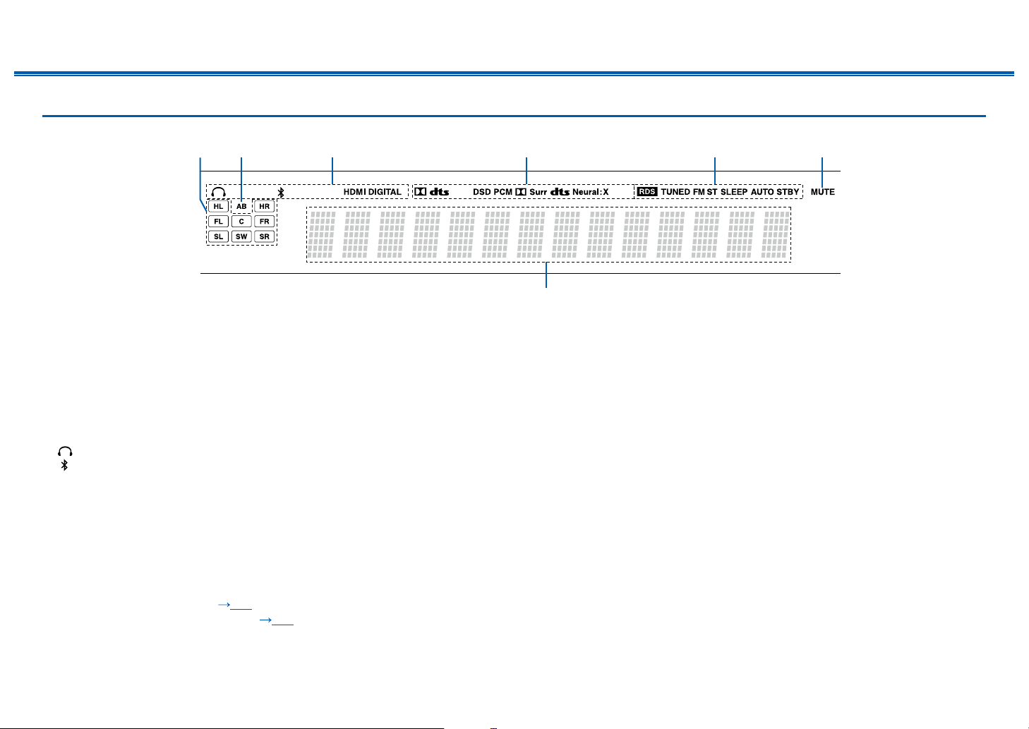
Display
1. Speaker/Channel display: Displays the output channel that corresponds to the
selected listening mode.
2. Displays the audio output destination.
A: Outputs audio only to the main room (ZONE A).
B: Outputs audio only to the separate room (ZONE B).
AB: Outputs audio to both the main room (ZONE A) and separate room (ZONE
B).
3. Lights in the following conditions.
: Headphones are connected.
: Connected by BLUETOOTH.
HDMI: HDMI signals are input and the HDMI input is selected.
DIGITAL: Digital signals are input and the digital input is selected.
4. Lights according to the type of input digital audio signal and the listening
mode.
5. Lights in the following conditions.
RDS (European, Australian and Asian models): Receiving RDS broadcasting.
TUNED: Receiving AM/FM radio.
FM ST: Receiving FM stereo.
SLEEP: Sleep timer is set. ( p79)
AUTO STBY: Auto Standby is set. ( p79)
6. Blinks when muting is on.
7. Displays various information of the input signals.
32
7
654
1
11
Contents
≫
Connections
≫
Playback
≫
Setup
≫
Front Panel≫ Rear Panel≫ Remote≫
Rear Panel
❏ For details, see ( p12)

12
Contents
≫
Connections
≫
Playback
≫
Setup
≫
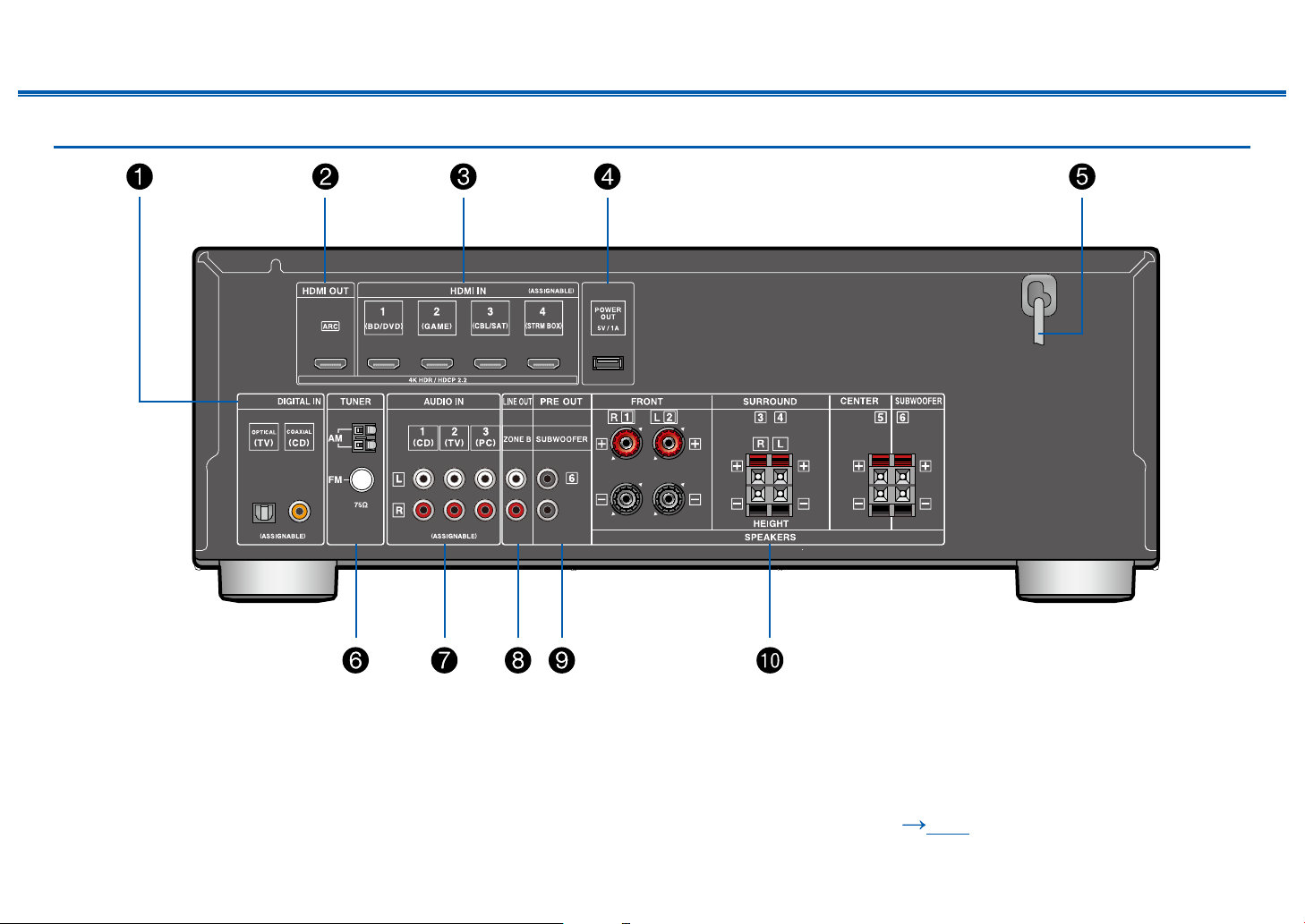
Front Panel≫ Rear Panel≫ Remote≫
1. DIGITAL IN OPTICAL/COAXIAL jacks: Input TV or AV component digital audio
signals with a digital optical cable or digital coaxial cable.
2. HDMI OUT jacks: Transmit video signals and audio signals with an HDMI
cable connected to a TV.
3. HDMI IN jacks: Transmit video signals and audio signals with an HDMI cable
connected to an AV component.
4. POWER OUT port: You can also supply power (5 V/1 A) to the Streaming
media player connected to the HDMI IN terminal of this unit with a USB cable.
( p32) The playback function of music les and power supply to smart
phones/tablets, or other devices are not supported.
5. Power cord
6. TUNER AM/FM terminal: Connect the supplied antennas.
7. AUDIO IN jacks: Input TV or AV component audio signals with an analog audio
cable.
8. ZONE B LINE OUT jacks: Output audio signals with an analog audio cable
connected to a pre-main amplier in a separate room (ZONE B).
9. SUBWOOFER PRE OUT jacks: Connect a powered subwoofer sold
separately with a subwoofer cable. Up to two powered subwoofers can be
connected. The same signal is output from each SUBWOOFER PRE OUT
jack.
10.
SPEAKERS terminals: Connect included speakers and subwoofer with
speaker cables. (FRONT L/R terminals of North American models support
banana plugs.)
13
Contents
≫
Connections
≫
Playback
≫
Setup
≫
Front Panel≫ Rear Panel≫ Remote≫
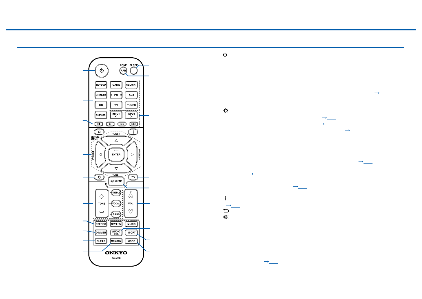
Remote Controller
1. ON/STANDBY button
2. Input selector buttons: Switches the input to be played.
3. Play buttons:
Used for playback operation of a BLUETOOTH-enabled device. If the unit
is switched to "CEC MODE" using the MODE button, an HDMI CEC function-enabled AV
component can be operated. (Depending on the device, operation may not be possible.)
4. Q (QUICK MENU) button:
Pressing this button during playback can make settings
such as "HDMI" and "Audio" quickly on the TV screen while playing.
( p81)
5. Cursor buttons and ENTER button: Select an item with the cursors, and press
ENTER to conrm your selection.
6. button: Display advanced setting items on the TV or the display to have a
more enjoyable experience with this unit. ( p65)
7. TONE button: Adjusts the sound quality. ( p48)
8. LISTENING MODE button: Select a listening mode ( p50).
9. DIMMER button: Switches the brightness of the display with three levels. It
cannot be turned off completely.
10.
CLEAR button: Deletes all characters you have entered when entering text on
the TV screen.
11.
MEMORY button: Used to register AM/FM radio stations. ( p42)
12.
SLEEP button: Set the sleep timer. Select the time from "30 min", "60 min" and
"90 min". ( p49)
13.
ZONE A/B button: Selects an audio output destination from among "ZONE A",
"ZONE B" and "ZONE A+B". ( p45)
14.
Input selector cursors: Switches the input to be played.
15.
button: Switches the information on the display and is used to operate RDS
( p44).
16.
button: Returns the display to the previous state while setting.
17.
button: Temporarily mutes audio. Press the button again to cancel muting.
18.
VOLUME buttons
19.
AUDIO SEL button: When a device is connected to two or more audio input
terminals for one input selector, you can select which audio input signal to play.
20.
M.OPT button: Turns on/off the MUSIC OPTIMIZER function that improves the
quality of the compressed audio.
21.
MODE button: Switches between automatic tuning and manual tuning for
AM/FM stations ( p40). Also, when an HDMI CEC function-enabled AV
component is connected to this unit, you can switch "3. Play buttons" between
"CEC MODE" and "RCV MODE" (normal mode).
14
Front Panel≫ Rear Panel≫ Remote≫
Contents
≫
Connections
≫
Playback
≫
Setup
≫
Speaker/Subwoofer
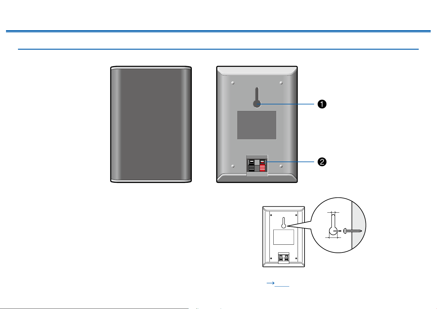
Front Speakers/Surround Speakers
Included front speakers and surround speakers can be used for both left and right
side. The sound quality does not differ when used for left or right side.
The grill net cannot be removed.
1. Wall mount hole: the speaker system may be mounted to a wall by suspending
speakers on wooden screw using the wall mount hole.
• Wooden wall mount screw is not included. Please consult with a
construction service personnel and prepare screw considering its type,
material, and length so it provides sufcient support. Moreover, please also
install a reinforcement panel, anchor, etc. if necessary.
• Our company bears no responsibility in the case of accident or injury
sustained due to improper installation, insufciently mounting, misuse,
natural disaster, etc.
2. Speaker jack: use the included speaker cable to connect to the main unit.
• Do not place objects on the speaker system. The speaker system may drops
or fall over by losing balance and may cause an injury.
10mm
4mm
❏ Notice ( p17)

15
Front Panel≫ Rear Panel≫ Remote≫
Contents
≫
Connections
≫
Playback
≫
Setup
≫
Center Speaker
The grill net cannot be removed.
1. Speaker jack: use the included speaker cable to connect to the main unit.
2. Wall mount hole: the speaker system may be mounted to a wall by suspending
speakers on wooden screw using the wall mount hole.
• Wooden wall mount screw is not included. Please consult with a
construction service personnel and prepare screw considering its type,
material, and length so it provides sufcient support. Moreover, please also
install a reinforcement panel, anchor, etc. if necessary.
• Our company bears no responsibility in the case of accident or injury
sustained due to improper installation, insufciently mounting, misuse,
natural disaster, etc.
• Do not place objects on the speaker system. The speaker system may drops
or fall over by losing balance and may cause an injury.
116mm
10mm
4mm
❏ Notice ( p17)
16
Front Panel≫ Rear Panel≫ Remote≫
Contents
≫
Connections
≫
Playback
≫
Setup
≫
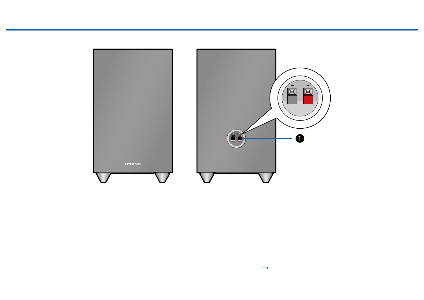
Subwoofer
1. Speaker jack: use the included speaker cable to connect to the main unit.
❏ Notice ( p17)

17
Front Panel≫ Rear Panel≫ Remote≫
Contents
≫
Connections
≫
Playback
≫
Setup
≫
Notice
• Do not place objects on the speaker system. The speaker system may drops
or fall over by losing balance and may cause an injury.
• Do not place on a shaky platform, sloping surface, or other unstable place.
The speaker system may drop or fall over by losing balance and may cause
an injury.
• Please select an installation site that has stable oor. If placed on a long-ber
carpet, the bers may contact the oscillator panel and cause irregular noise.
• Install the unit away from the tuner's antenna cable. Noise may be generated
if the two are too close together. If this happens, keep the main unit away from
the antenna and antenna cable.
• If a television or other device is nearby, noise interference may be produced
by the speakers due to electrical interference, etc. even if audio device power
is disconnected. If such noise interference is problematic, further separate the
speakers.
• The speaker unit for this product uses an extremely strong magnet. Do not
place drivers or other metallic objects near the front of the speaker system.
Doing so may cause injury from objects being attracted or damage the
oscillation panel. Moreover, do not place cash cards, oppy disks, or other
magnetic media near the speaker. The magnetic eld may cause those items
to be unusable or lose data.
• This unit is not designed with anti-magnetic shielding. Nearby CRT televisions
and computers may experience screen color distortion due to the presence the
magnetic eld. In such cases, move the speakers further away before use.
• This unit is capable of regular music playback. However, if any of the following
special signals are input, circuits may burnout due to excessive current.
Please exercise caution.
1. Noise resulting from incorrect FM channel reception
2. Noise from oscillator, electronic music device, or other high-frequency
component
3. Audio Check CD and other special signal sounds
4. Feedback from microphone
5. Sound produced when tape recorder is fast forwarded
6. When amplier is reverberating
7. Shock sound when plugging and unplugging pin cord or other connection
jacks
Maintenance
Periodically wiped the top and side surfaces of this product with a soft cloth.
When particularly dirty, soak the cloth in a diluted neutral cleaning solution and
squeeze out excess liquid before cleaning. Then, nish wiping with a dry cloth.
If using a chemical cloth, please read the warning label afxed to the cleaning
product.
18
Front Panel≫ Rear Panel≫ Remote≫
Contents
≫
Connections
≫
Playback
≫
Setup
≫
Connections
Connecting speakers 19
Connecting the TV 29
Connecting Playback Devices 32
Connecting an AV Component in a Separate Room
(ZONE B Connection) 34
Connecting Antennas 35
Connecting the Power Cord 36

19
Front Panel≫ Rear Panel≫ Remote≫
Contents
≫
Connections
≫
Playback
≫
Setup
≫
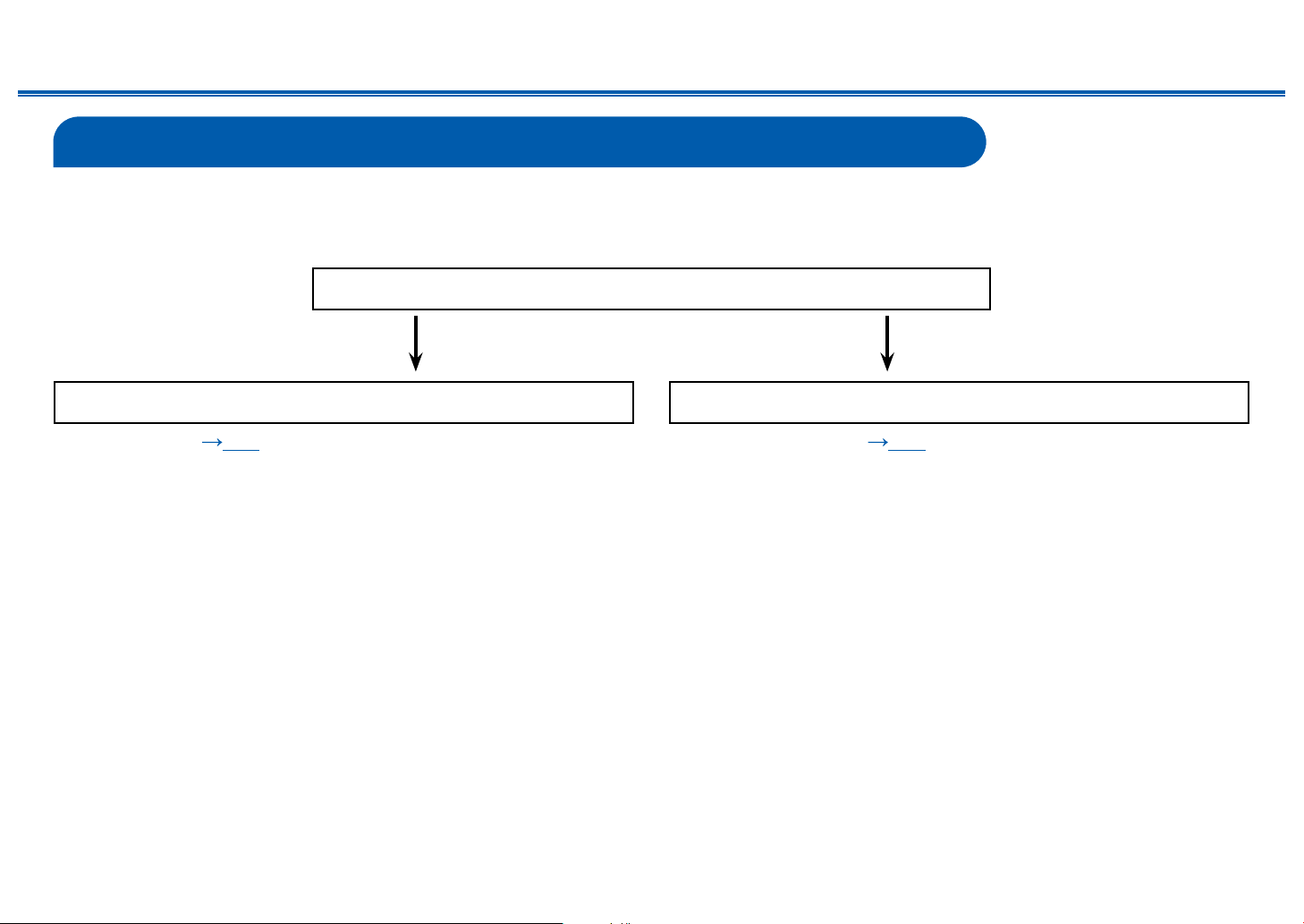
Connecting speakers
You can select the layout of speakers to be installed from various patterns when using this unit. Use the following ow chart to select the speaker layout that suits your
speakers and usage environment. You can check the connection method and default settings.
Use height speakers?
Yes No
• 3.1.2 Channel System ( p27) • 5.1 Channel System ( p26)

20
Front Panel≫ Rear Panel≫ Remote≫
Contents
≫
Connections
≫
Playback
≫
Setup
≫
Speaker Installation
5.1 Channel System
a
b
12
34
5
6
a: 22° to 30°, b: 120°
This is a basic 5.1 Channel System. Front speakers output the front stereo
sound, and a center speaker outputs the sound of the center of the screen,
such as dialogs and vocals. Surround speakers create the back sound eld.
Subwoofer reproduces the bass sound, and creates the rich sound eld.
The front speakers should be positioned at ear height while the surround
speakers should be positioned just above ear height. The center speaker should
be set up facing the listening position at an angle. Placing the subwoofer between
the center speaker and the front speaker gives you a natural sound even when
playing music sources.
1,2 Front Speakers
3,4 Surround Speakers
5 Center Speaker
6 Subwoofer
❏ Speaker Layouts and Selectable Listening
Modes ( p52)

21
Front Panel≫ Rear Panel≫ Remote≫
Contents
≫
Connections
≫
Playback
≫
Setup
≫
3.1.2 Channel System
A 3.1.2 Channel System is a speaker layout consisting of a 3.1 Channel System that includes front speakers, center speaker and subwoofer, and added height
speakers. Select the height speakers that suit your speakers and usage environment from the following three types.
❏ Front High Speakers Installation Example
( p22)
❏ Ceiling Speakers Installation Example
( p23)
❏ Dolby Enabled Speakers (Dolby Speakers)
Installation Example ( p24)
22
Front Panel≫ Rear Panel≫ Remote≫
Contents
≫
Connections
≫
Playback
≫
Setup
≫
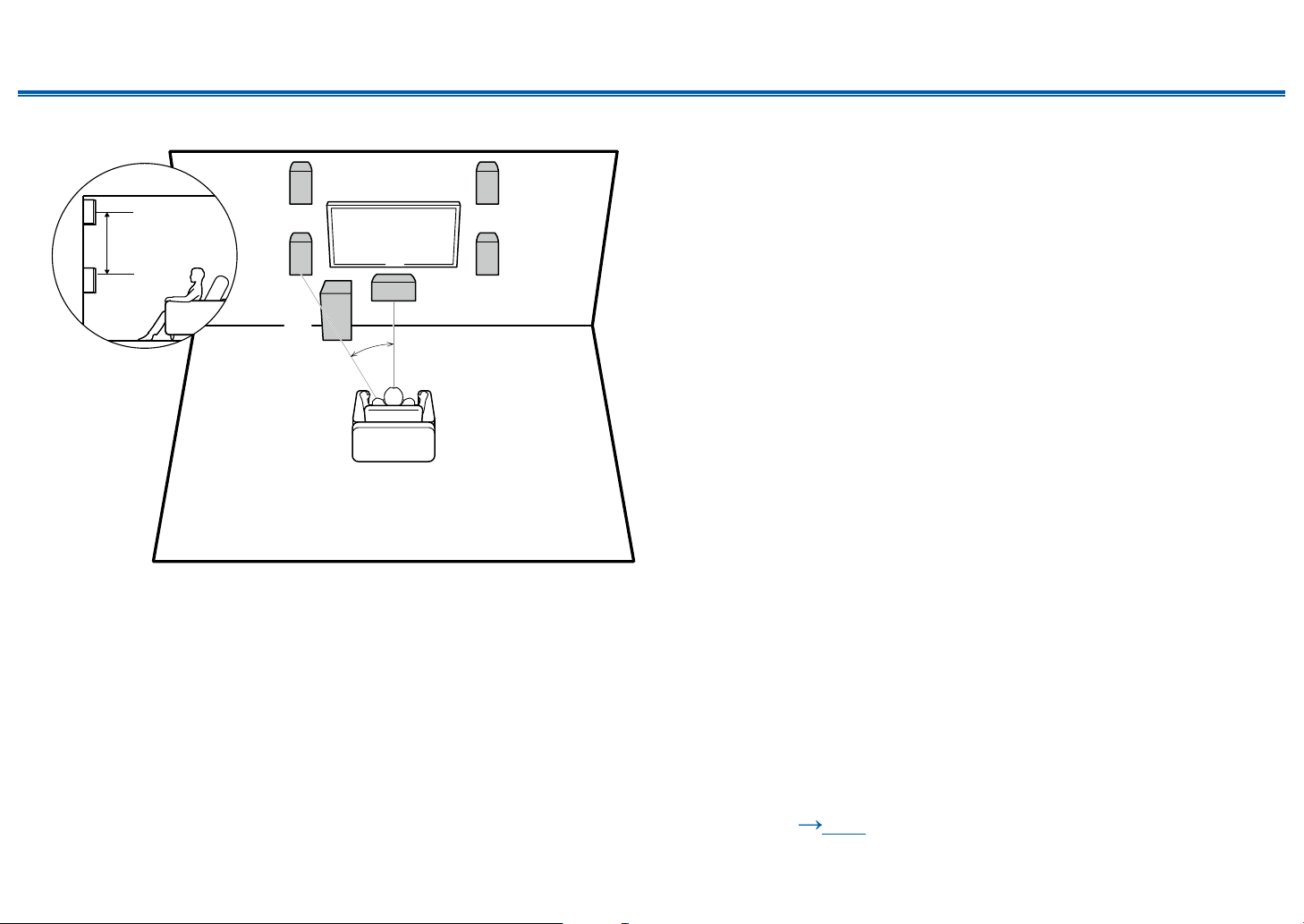
❏ Front High Speakers Installation Example
a
12
6
3
4
5
a: 22° to 30°
3´ (0.9 m)
or more
This is a 3.1-channel system consisting of front speakers, a center speaker, and
a subwoofer, with the installation of front high speakers, a type of height speaker.
Installing the height speakers will enrich the sound eld feeling in the upper
space. Front high speakers should be situated at least 3'/0.9 m higher than the
front speakers.
They should also be put directly above the front speakers.
1,2 Front Speakers
3,4 Front High Speakers
5 Center Speaker
6 Subwoofer
❏ Speaker Layouts and Selectable Listening
Modes ( p52)

23
Front Panel≫ Rear Panel≫ Remote≫
Contents
≫
Connections
≫
Playback
≫
Setup
≫
❏ Ceiling Speakers Installation Example
a
12
6
5
b
3
4
*
*
a: 22° to 30°, b: 65° to 100°
This is a 3.1-channel system consisting of inclueded front speakers, a center
speaker, and a subwoofer, with the addition of top middle speakers sold
separately, a type of height speaker. Installing the height speakers will enrich
the sound eld feeling in the upper space. Fit top middle speakers on the ceiling
directly above the listening position. The distance between each pair should
match the distance between the two front speakers.
• Dolby Laboratories recommends the setups of these types of height speakers
to obtain the best Dolby Atmos effect.
1,2 Front Speakers
3,4 Top Middle Speakers*
5 Center Speaker
6 Subwoofer
* Optional items
❏ Speaker Layouts and Selectable Listening
Modes ( p52)
24
Front Panel≫ Rear Panel≫ Remote≫
Contents
≫
Connections
≫
Playback
≫
Setup
≫
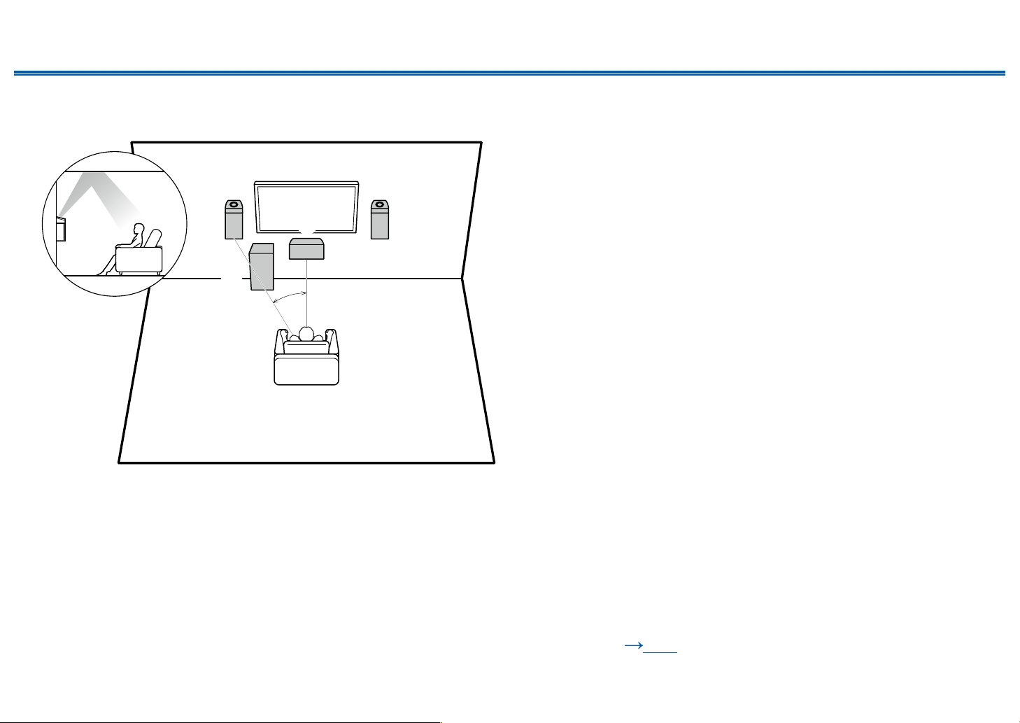
❏ Dolby Enabled Speakers (Dolby Speakers)
Installation Example
a
5
12
34
6
**
**
a: 22° to 30°
Separately sold Dolby-enabled speakers have been selected as the height
speakers for this system. Dolby enabled speakers are special speakers designed
to face the ceiling, so that the sound is heard from overhead by bouncing the
sound off the ceiling.
Place Dolby enabled speakers (front) above the front speakers. The front
speakers included with this unit are not designed for Dolby enabled speakers to
be installed on top of them, so do not use them with this system. Be sure to use
sold separately front speakers.
1,2 Front Speakers*
3,4 Dolby Enabled Speakers (Front)*
5 Center Speaker
6 Subwoofer
* Optional items
❏ Speaker Layouts and Selectable Listening
Modes ( p52)
25
Front Panel≫ Rear Panel≫ Remote≫
Contents
≫
Connections
≫
Playback
≫
Setup
≫
Speaker Connections and "Speaker Setup" Settings
Connections
(Note) Speaker Impedance
When using the included speakers, setup explained in this section is not required. When using speakers sold separately, use speakers with impedance of 4 Ω to
16 Ω. If any of the speakers to be connected has an impedance of 4 Ω or more and less than 6 Ω, set "Speaker Impedance" to "4 ohms" for "Speaker Setup" in the
Initial Setup section ( p83). When setting "Speaker Impedance" from the Setup menu, press on the remote controller, and set "2. Speaker" - "Conguration" -
"Speaker Impedance" ( p71) to "4 ohms".
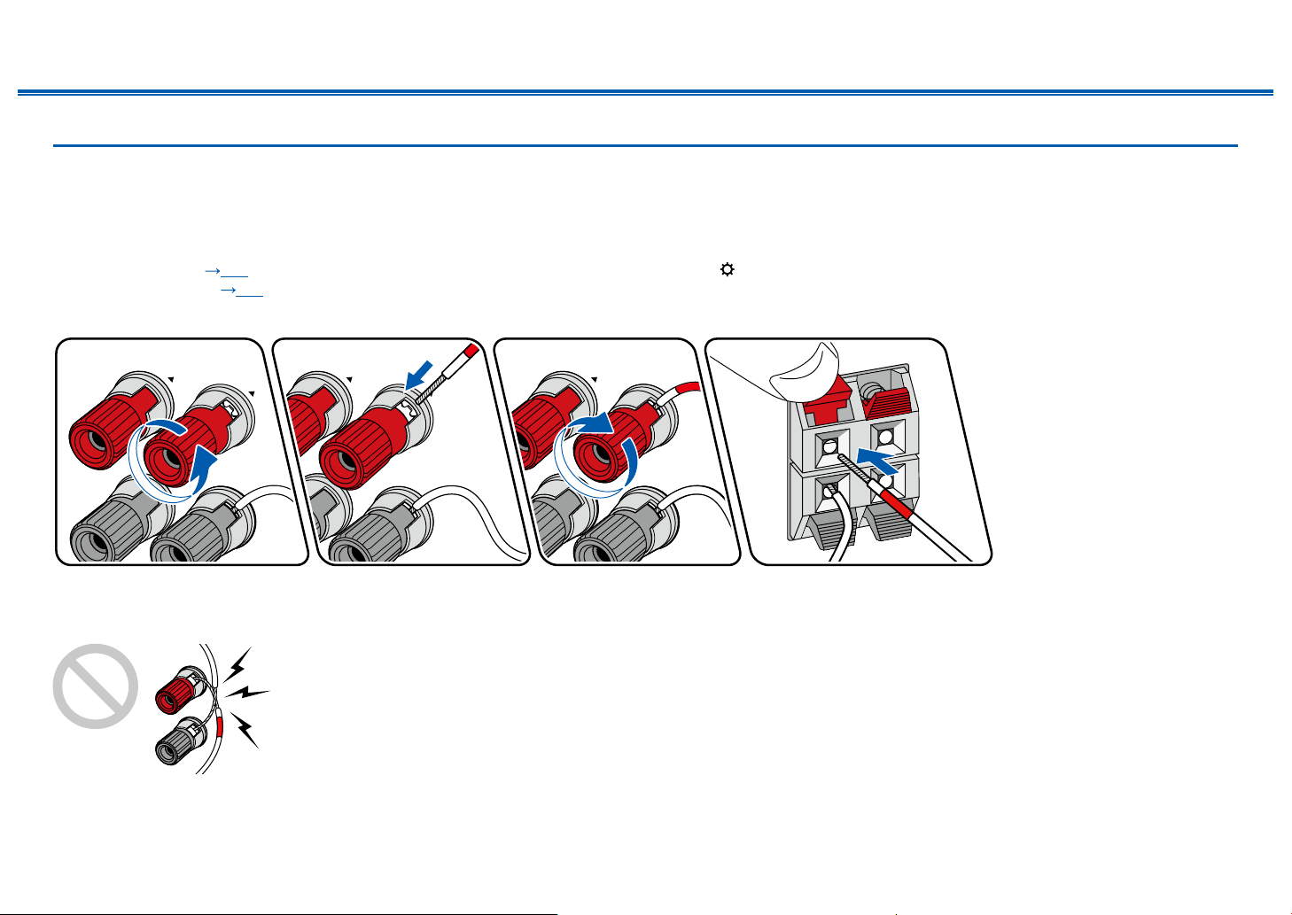
Connect the Speaker Cables
Make correct connection between the unit's jacks and speaker's jacks (+ side to + side, and - side to - side) for each channel. If the connection is wrong, a bass sound
will not be reproduced properly due to reverse phase. The wires exposed from the tip of the speaker cable do not stick out of the speaker terminal when connecting. If
the exposed wires touch the rear panel, or the + side and - side wires touch each other, a malfunction may occur.

26
Front Panel≫ Rear Panel≫ Remote≫
Contents
≫
Connections
≫
Playback
≫
Setup
≫
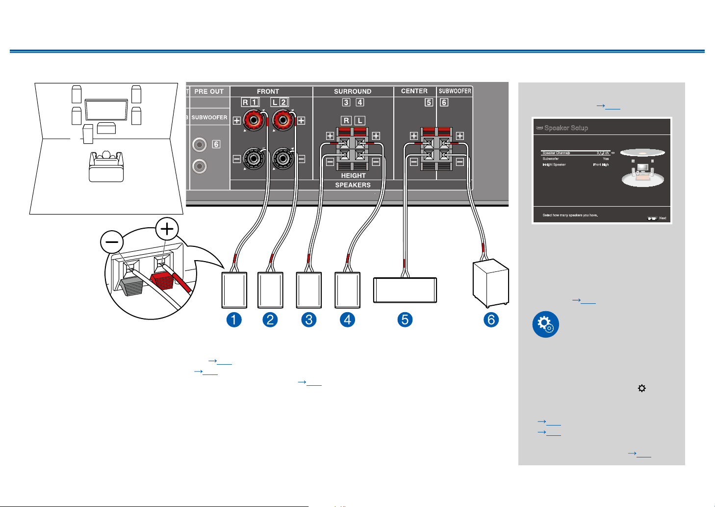
5.1 Channel System
12
34
5
6
This is a basic 5.1 Channel System. For details of the speaker layout, refer to "Speaker Installation" ( p20).
"Speaker Setup" settings during
Initial Setup ( p84)
Speaker Setup
Select how many speakers you have.
Next
ENTER
Speaker Channels 5.1 ch
Yes
Subwoofer
- - -Height Speaker
• Speaker Channels: 5.1 ch
• Subwoofer: Yes
• Height Speaker: ---
• Speaker Impedance: Set any
value ( p25)
Setup
In order to optimize the sound eld
effect, some settings must be made
in the Setup menu after the Initial
Setup is completed. Press on
the remote controller, then set
"2. Speaker" - "Distance"
( p72) and "Level Calibration"
( p73).
27
Front Panel≫ Rear Panel≫ Remote≫
Contents
≫
Connections
≫
Playback
≫
Setup
≫
3.1.2 Channel System
12
6
34
5
This is a combination of the 3.1 Channel System and front high speakers. A front high speaker is a type of height speaker.
You can select only one set of height speakers from the following three types for connection.
❏ Front High Speakers Installation Example ( p22)
❏ Ceiling Speakers Installation Example ( p23)
❏ Dolby Enabled Speakers (Dolby Speakers) Installation Example ( p24)
"Speaker Setup" settings during
Initial Setup ( p84)
Speaker Setup
Select how many speakers you have.
Next
ENTER
Speaker Channels 3.1.2 ch
Yes
Subwoofer
Front HighHeight Speaker
• Speaker Channels: 3.1.2 ch
• Subwoofer: Yes
• Height Speaker: Select the
type of height speaker actually
installed.
• Speaker Impedance: Set any
value ( p25)
Setup
In order to optimize the sound eld
effect, some settings must be made
in the Setup menu after the Initial
Setup is completed. Press on
the remote controller, then set
"2. Speaker" - "Distance"
( p72) and "Level Calibration"
( p73).When using separately
sold speakers, also set "2.
Speaker" - "Crossover"( p71).

28
Front Panel≫ Rear Panel≫ Remote≫
Contents
≫
Connections
≫
Playback
≫
Setup
≫
Speaker combinations
Speaker Channels FRONT CENTER SURROUND HEIGHT SUBWOOFER
2.1 ch
3.1 ch
4.1 ch
5.1 ch
2.1.2 ch
3.1.2 ch
29
Front Panel≫ Rear Panel≫ Remote≫
Contents
≫
Connections
≫
Playback
≫
Setup
≫
Connecting the TV
Connect this unit between a TV and AV component. Connecting this unit with the TV can output the video and audio signals of the AV component to the TV, or play the
audio of the TV on this unit. Connection with the TV differs depending on whether the TV supports the ARC (Audio Return Channel) function or not. The ARC function
transmits the audio signals of the TV via an HDMI cable, and plays the audio of the TV on this unit. To check if the TV supports the ARC function, refer to the instruction
manual of the TV, etc.
Yes No
Does your TV support the ARC function?
• To ARC TV ( p30) • To Non-ARC TV ( p31)

30
Front Panel≫ Rear Panel≫ Remote≫
Contents
≫
Connections
≫
Playback
≫
Setup
≫
To ARC TV
If the TV supports the ARC (Audio Return Channel) function (*), use only the
HDMI cable to connect with the TV. Use the ARC-compatible HDMI IN jack of the
TV for connection.
• If a 4K high-quality video is played, use a Premium High Speed HDMI Cable
or Premium High Speed HDMI Cable with Ethernet whose package has a
"PREMIUM Certied Cable" label.
Setup
• Settings are required to use the ARC function. Select "Yes" for "2. ARC Setup"
in Initial Setup ( p83). If "No, Skip" is selected, settings are required in the
Setup menu after Initial Setup is completed. Press on the remote controller,
and set "5. Hardware" - "HDMI" - "Audio Return Channel" to "On". ( p78)
• For detailed settings for TV connection, CEC function and audio output, refer
to the instruction manual of the TV.
(*) ARC function: This function transmits the audio signals of the TV via an
HDMI cable, and plays the audio of the TV on this unit. Connection to an ARC-
compatible TV is complete with one HDMI cable. To check if the TV supports the
ARC function, refer to the instruction manual of the TV, etc.
a HDMI cable
a
TV
Loading...