


HT-R820THX

HT-S870_En.book Page 1 Monday, September 13, 2004 5:15 PM
Contents
Introduction .....................................2
6.1ch Home Theater System
Connection.....................................18
HT-S870
AV Receiver (HT-R820THX)
6.1ch Speaker System (HTP-820)
Instruction Manual
Thank you for purchasing an Onkyo 6.1ch Home
Theater System. Please read this manual thoroughly
before making connections and plugging in the unit.
Following the instructions in this manual will enable
you to obtain optimum performance and listening
enjoyment from your new 6.1ch Home Theater System.
Please retain this manual for future reference.
Turning On & First Time Setup..... 33
Basic Operation
Playing your AV components ....... 34
Using the Tuner ............................36
Enjoying the Listening Modes .....40
Advanced Operation ..................... 45
Troubleshooting ............................58
En
HT-S870_En.book Page 2 Monday, September 13, 2004 5:15 PM
WARNING:
TO REDUCE THE RISK OF FIRE OR ELECTRIC
SHOCK, DO NOT EXPOSE THIS APPARATUS
TO RAIN OR MOISTURE.
CAUTION:
TO REDUCE THE RISK OF ELECTRIC SHOCK,
DO NOT REMOVE COVER (OR BACK). NO
USER-SERVICEABLE PARTS INSIDE. REFER
SERVICING TO QUALIFIED SERVICE
PERSONNEL.
Important Safety Instructions
1. Read these instructions.
2. Keep these instructions.
3. Heed all warnings.
4. Follow all instructions.
5. Do not use this apparatus near water.
6. Clean only with dry cloth.
7. Do not block any ventilation openings. Install in
accordance with the manufacturer’s instructions.
8. Do not install near any heat sources such as radiators, heat registers, stoves, or other apparatus
(including amplifiers) that produce heat.
9. Do not defeat the safety purpose of the polarized or
grounding-type plug. A polarized plug has two
blades with one wider than the other. A grounding
type plug has two blades and a third grounding
prong. The wide blade or the third prong are provided for your safety. If the provided plug does not
fit into your outlet, consult an electrician for
replacement of the obsolete outlet.
10. Protect the power cord from being walked on or
pinched particularly at plugs, convenience receptacles, and the point where they exit from the apparatus.
11. Only use attachments/accessories specified by the
manufacturer.
12.
Use only with the cart, stand,
tripod, bracket, or table specified by the manufacturer, or
sold with the apparatus.
When a cart is used, use caution when moving the cart/
apparatus combination to
avoid injury from tip-over.
13. Unplug this apparatus during lightning storms or
when unused for long periods of time.
14. Refer all servicing to qualified service personnel.
Servicing is required when the apparatus has been
damaged in any way, such as power-supply cord or
plug is damaged, liquid has been spilled or objects
have fallen into the apparatus, the apparatus has
been exposed to rain or moisture, does not operate
normally, or has been dropped.
PORTABLE CART WARNING
S3125A
WARNING
RISK OF ELECTRIC SHOCK
DO NOT OPEN
The lightning flash with arrowhead symbol, within an
equilateral triangle, is intended to alert the user to the
presence of uninsulated “dangerous voltage” within
the product’s enclosure that may be of sufficient
magnitude to constitute a risk of electric shock to
persons.
The exclamation point within an equilateral triangle is
intended to alert the user to the presence of important
operating and maintenance (servicing) instructions in
the literature accompanying the appliance.
AVIS
RISQUE DE CHOC ELECTRIQUE
NE PAS
OUVRIR
15. Damage Requiring Service
Unplug the apparatus from the wall outlet and refer
servicing to qualified service personnel under the
following conditions:
A. When the power-supply cord or plug is damaged,
B. If liquid has been spilled, or objects have fallen
into the apparatus,
C. If the apparatus has been exposed to rain or
water,
D. If the apparatus does not operate normally by
following the operating instructions. Adjust only
those controls that are covered by the operating
instructions as an improper adjustment of other
controls may result in damage and will often
require extensive work by a qualified technician
to restore the apparatus to its normal operation,
E. If the apparatus has been dropped or damaged in
any way, and
F. When the apparatus exhibits a distinct change in
performance this indicates a need for service.
16. Object and Liquid Entry
Never push objects of any kind into the apparatus
through openings as they may touch dangerous voltage points or short-out parts that could result in a
fire or electric shock.
The apparatus shall not be exposed to dripping or
splashing and no objects filled with liquids, such as
vases shall be placed on the apparatus.
Don’t put candles or other burning objects on top of
this unit.
17. Batteries
Always consider the environmental issues and follow local regulations when disposing of batteries.
18. If you install the apparatus in a built-in installation,
such as a bookcase or rack, ensure that there is adequate ventilation.
Leave 20 cm (8") of free space at the top and sides
and 10 cm (4") at the rear. The rear edge of the shelf
or board above the apparatus shall be set 10 cm (4")
away from the rear panel or wall, creating a flue-like
gap for warm air to escape.
2

HT-S870_En.book Page 3 Monday, September 13, 2004 5:15 PM
Precautions
1. Recording Copyright —Unless it’s for personal use
only, recording copyrighted material is illegal without the permission of the copyright holder.
2. AC Fuse —The AC fuse inside the HT-R820THX
and SKW-820 is not user-serviceable. If you cannot
turn on the HT-R820THX and SKW-820, contact
your Onkyo dealer.
3. Care —Occasionally you should dust the HT-S870
all over with a soft cloth. For stubborn stains, use a
soft cloth dampened with a weak solution of mild
detergent and water. Dry the HT-S870 immediately
afterwards with a clean cloth. Don’t use abrasive
cloths, thinners, alcohol, or other chemical solvents,
because they may damage the finish or remove the
panel lettering.
4. Power
WARNING
BEFORE PLUGGING IN THE UNIT FOR THE
FIRST TIME, READ THE FOLLOWING SECTION CAREFULLY.
AC outlet voltages vary from country to country.
Make sure that the voltage in your area meets the
voltage requirements printed on the HT-R820THX’s
rear panel (e.g., AC 120 V, 60 Hz).
Setting the [STANDBY/ON] switch to STANDBY
does not fully shutdown the HT-R820THX. If you
do not intend to use the HT-R820THX for an
extended period, remove the power cord from the
AC outlet.
Memory backup
The HT-R820THX uses a battery-less memory backup
system in order to retain radio presets and other settings
when it’s unplugged or in the case of a power failure.
Although no batteries are required, the HT-R820THX
must be plugged into an AC outlet in order to charge the
backup system.
Once it has been charged, the HT-R820THX will retain
the settings for several weeks, although this depends on
the environment and will be shorter in humid climates.
For U.S. models
Note to CATV system installer:
This reminder is provided to call the CATV system
installer's attention to Section 820-40 of the NEC which
provides guidelines for proper grounding and, in particular, specifies that the cable ground shall be connected
to the grounding system of the building, as close to the
point of cable entry as practical.
FCC Information for User
CAUTION:
The user changes or modifications not expressly
approved by the party responsible for compliance could
void the user’s authority to operate the equipment.
NOTE:
This equipment has been tested and found to comply
with the limits for a Class B digital device, pursuant to
Part 15 of the FCC Rules. These limits are designed to
provide reasonable protection against harmful interference in a residential installation.
This equipment generates, uses and can radiate radio
frequency energy and, if not installed and used in accordance with the instructions, may cause harmful interference to radio communications. However, there is no
guarantee that interference will not occur in a particular
installation. If this equipment does cause harmful interference to radio or television reception, which can be
determined by turning the equipment off and on, the
user is encouraged to try to correct the interference by
one or more of the following measures:
• Reorient or relocate the receiving antenna.
• Increase the separation between the equipment and
receiver.
• Connect the equipment into an outlet on a circuit different from that to which the receiver is connected.
• Consult the dealer or an experienced radio/TV technician for help.
For Canadian Models
NOTE:
COMPLIES WITH CANADIAN ICES-003.
For models having a power cord with a polarized plug:
CAUTION:
MATCH WIDE BLADE OF PLUG TO WIDE SLOT,
FULLY INSERT.
THIS CLASS B DIGITAL APPARATUS
TO PREVENT ELECTRIC SHOCK,
Modèle canadien
REMARQUE:
LA CLASSE B EST CONFORME À LA NORME
NMB-003 DU CANADA.
Sur les modèles dont la fiche est polarisée:
ATTENTION:
TRIQUES, INTRODUIRE LA LAME LA PLUS
LARGE DE LA FICHE DANS LA BORNE CORRESPONDANTE DE LA PRISE ET POUSSER
JUSQU’AU FOND.
CET APPAREIL NUMÉRIQUE DE
POUR ÉVITER LES CHOCS ÉLEC-
3

HT-S870_En.book Page 4 Monday, September 13, 2004 5:15 PM
7.
4.
5.
6.
1.
2.
3.
Speaker Precautions
Placement
• The speaker cabinets are made out of wood and are
therefore sensitive to extreme temperatures and
humidity, do not put them in locations subject to direct
sunlight or in humid places, such as near an air conditioner, humidifier, bathroom, or kitchen.
• Do not put water or other liquids close to the speakers.
If liquid is spilled over the speakers, the drive units
may be damaged.
• Speakers should only be placed on sturdy, flat surfaces
that are free from vibration. Putting them on uneven or
unstable surfaces, where they may fall and cause damage, will affect the sound quality.
• Subwoofer is designed to be used in the upright vertical position only. Do not use it in the horizontal or
tilted position.
• If the unit is used near a turntable or CD player, howling or slipping of sound may occur. To prevent this,
move the unit away from the turntable or CD player
otherwise lower the unit’s output level.
Using Close to a TV or Computer
TVs and computer monitors are magnetically sensitive
devices and as such are likely to suffer discoloration or
picture distortion when conventional speakers are
placed nearby. To prevent this, the SKF-820F and SKC820C feature internal magnetic shielding. In some situations, however, discoloration may still be an issue, in
which case you should turn off your TV or monitor, wait
15 to 30 minutes, and then turn it back on again. This
normally activates the degaussing function, which neutralizes the magnetic field, thereby removing any discoloration effects. If discoloration problems persist, try
moving the speakers away from your TV or monitor.
Note that discoloration can also be caused by a magnet
or demagnetizing tool that’s too close to your TV or
monitor.
Do not place surround speakers close to TV or a computer monitor because they have no magnetic shield.
Input Signal Warning
The speakers can handle the specified input power when
used for normal music reproduction. If any of the following signals are fed to them, even if the input power is
within the specified rating, excessive current may flow
in the speaker coils, causing burning or wire breakage:
Interstation noise from an untuned FM radio.
Sound from fast-forwarding a cassette tape.
High-pitched sounds generated by an oscillator,
electronic musical instrument, and so on.
Amplifier oscillation.
Special test tones from audio test CDs and so on.
Thumps and clicks caused by connecting or disconnecting audio cables (Always turn off your amplifier
before connecting or disconnecting cables.)
Microphone feedback.
Features
Amp
• 6-channel amplifier
• 130 watts per channel min. RMS at 8 Ω , 2 channels
driven from 20 Hz to 20 kHz with no more than 0.08%
total harmonic distortion
• WRAT (Wide Range Amplifier Technology)
• Optimum gain volume circuitry
• OptiResponse™ Equalizer (OR-EQ™)
Processing
• Dolby
• DTS, DTS-ES Matrix/Discrete, DTS Neo:6, and DTS
• THX Surround EX
• THX Select certified
• Linear PCM 96 kHz/24-bit D/A converters on all
*2
Digital EX and Dolby Pro Logic IIx
96/24 processing
channels
*3
*4
Audio/Video
• HDTV-capable component video (2 inputs, 1 output)
•4 S-Video inputs, 2 outputs
•4 assignable digital inputs (3 optical, 1 coaxial)
• Subwoofer pre out
• Color-coded multichannel input for use with Super
Audio CD and DVD-Audio
• A/B speaker drive
• Color-coded speaker terminal posts
FM/AM Tuner
• 30 FM/AM presets
• FM/AM auto tuning
Remote Controller
• Preprogrammed for use with other AV components
Speaker
• Color coded speaker cable
• A-OMF cone (front and center speakers)
• Color coded and gold plating binding post terminals
*1. OptiResponse and OR-EQ are trademarks of Onkyo Cor-
poration.
*2. Manufactured under license from Dolby Laboratories.
“Dolby”, “Pro Logic”, “Surround EX” and the double-D
symbol are trademarks of Dolby Laboratories.
*3. “DTS,” “DTS 96/24,” “DTS-ES,” and “Neo:6” are trade-
marks of Digital Theater Systems, Inc.
*4. “THX” is a trademark or registered trademark of THX Ltd.
“Surround EX” is a trademark of Dolby Laboratories. Used
under authorization. All rights reserved.
*1
function
4
HT-S870_En.book Page 5 Monday, September 13, 2004 5:15 PM
THX Select
Before any home theater component can be THX
Select certified, it must pass a rigorous series of quality and performance tests. Only then can a product
feature the THX Select logo, which is your guarantee
that the Home Theater products you purchase will
give you superb performance for many years to come.
THX Select requirements define hundreds of parameters, including power amplifier performance, and preamplifier performance and operation for both digital
and analog domains. THX Select receivers also feature proprietary THX technologies (e.g., THX Mode)
which accurately translate movie soundtracks for
home theater playback.
Table of Contents
Introduction
Important Safety Instructions................2
Precautions.............................................3
Speaker Precautions..............................4
Features...................................................4
Supplied Accessories ............................6
Before Using the HT-R820THX ..............7
Front & Rear Panels ...............................8
Speaker Package..................................11
Remote Controller ................................12
Connection
Connecting Speakers........................... 18
Connecting Antenna ............................20
Connecting the HT-R820THX...............22
Turning on & First Time Setup ............. 33
Basic Operation
Playing Your AV Components.............34
Using the Tuner ....................................36
Common Functions..............................38
Enjoying the listening Modes
Using the Listening Modes..................40
Advanced Operation
Recording.............................................. 45
Advanced Function ..............................46
Advanced Setup ...................................48
Controlling Other Components...........52
Troubleshooting .................................... 58
Specifications .......................................62
5
HT-S870_En.book Page 6 Monday, September 13, 2004 5:15 PM
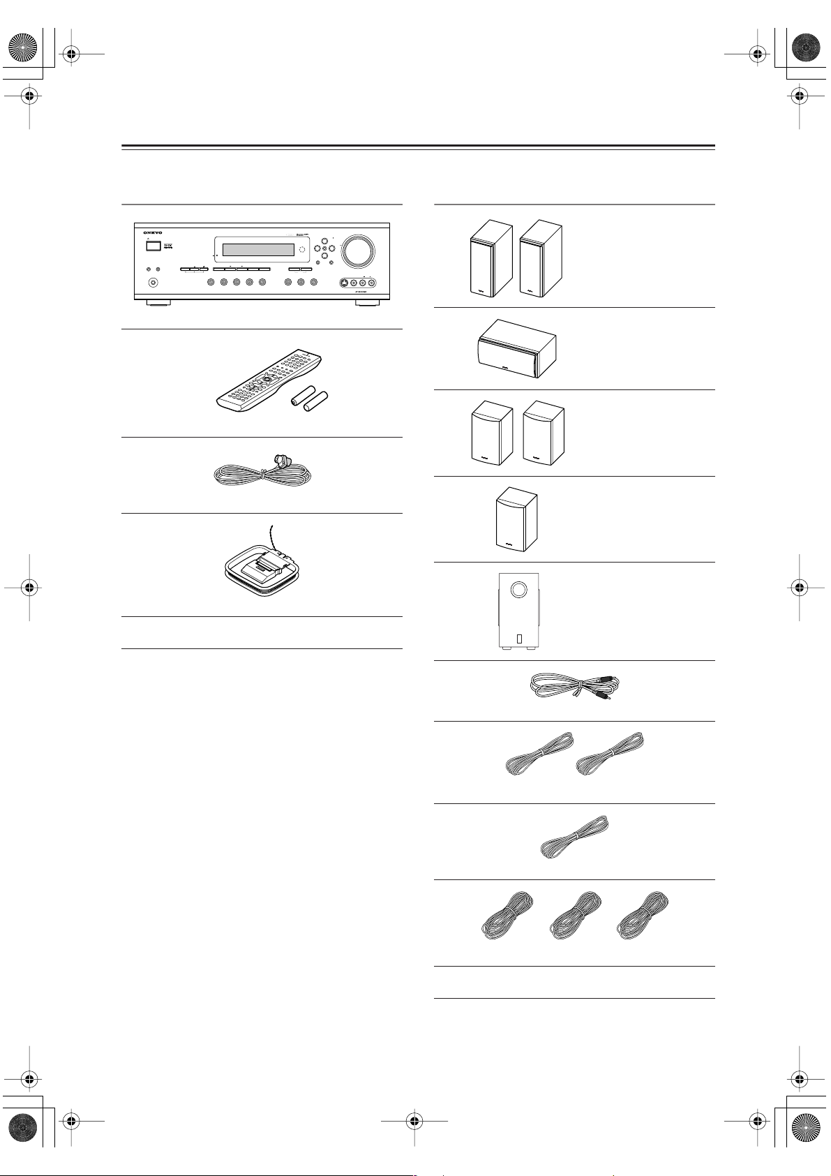
Supplied Accessories
Make sure you have the following accessories:
HT-R820THX
MEMORY
TAPE TUNER
TUNING
ENTER
RETURNSETUP
CLEAR
D
C
STANDBY/ON
STANDBY
LISTENING
DISPLAYTONE TUNING MODEDIGITAL INPUT
SPEAKERSBA
PHONES
THX
MODE
1
VIDEO
DVD
MULTI CH
VIDEO
VIDEO 2
3
VCR
HT-R820THX
Remote controller & two batteries (AA/R6)
Indoor FM antenna
HTP-820
MASTER VOLUME
PRESET
INPUT
VIDEO 3
VIDEO
LR
S VIDEO
AUDIO
HT-R820THX
Front speakers
(SKF-820 FL/FR)
Center speaker
(SKC-820C)
Surround speakers
(SKM-820 SL/SR)
Surround back speaker
(SKB-820)
AM loop antenna
THX Ultimate Demo Disc
* In catalogs and on packaging, the letter added to the end of
the product name indicates the color of the HT-S870. Specifications and operation are the same regardless of color.
Subwoofer (SKW-820)
RCA analog audio cable for subwoofer 10ft. (3m)
(Red) (White)
Speaker cable for front speakers 15 ft. (4.5 m)
(Green)
Speaker cable for center speaker 10 ft. (3 m)
(Blue) (Gray) (Brown)
Speaker cables for surround speakers 30 ft. (9 m)
Cork Spacer x 24
6

HT-S870_En.book Page 7 Monday, September 13, 2004 5:15 PM
Before Using the HT-R820THX
Installing the Batteries
To open the battery compartment, press
1
the small hollow and slide off the cover.
Insert the two supplied batteries (AA/R6)
2
in accordance with the polarity diagram
inside the battery compartment.
Put the cover onto the remote controller
3
and slide it shut.
Notes:
• The batteries should last for about six months,
although this will vary with usage.
• If the remote controller doesn’t work reliably, try
replacing the batteries.
• Don’t mix new and old batteries or different types of
batteries.
• If you intend not to use the remote controller for a long
time, remove the batteries to prevent damage from
leakage or corrosion.
• Expired batteries should be removed as soon as possible to prevent damage from leakage or corrosion.
Using the Remote Controller
To use the remote controller, point it at the HTR820THX’s remote control sensor, as shown below.
Remote control sensor
STANDBY indicator
30˚
Notes:
• The remote controller may not work reliably if the HTR820THX is subjected to bright light, such as direct
sunlight or inverter-type fluorescent lights. Keep this
in mind when installing.
• If another remote controller of the same type is used in
the same room, or the HT-R820THX is installed close
to equipment that uses infrared rays, the remote controller may not work reliably.
• Don’t put anything, such as a book, on the remote controller, because the buttons may be pressed inadvertently, thereby draining the batteries.
• The remote controller may not work reliably if the HTR820THX is installed in a rack behind colored glass
doors. Keep this in mind when installing.
• The remote controller will not work if there’s an obstacle between it and the HT-R820THX’s remote control
sensor.
30˚
HT-R820THX
(5 m)
Approx. 16 ft.
7

HT-S870_En.book Page 8 Monday, September 13, 2004 5:15 PM
Front & Rear Panels
Front Panel
123457 896 J
STANDBY/ON
STANDBY
MULTI CH
THX
DVD
SPEAKERS BA
PHONES
NLM
For detailed information, refer to the pages in
parenthesis.
STANDBY/ON button (33)
A
This button is used to set the HT-R820THX to On
or Standby.
STANDBY indicator (33)
B
This indicator lights up when the HT-R820THX is
in Standby mode, and it flashes while a signal is
being received from the remote controller.
THX button (41)
C
This button is used to select the THX listening
mode.
LISTENING MODE [ ] [ ] buttons (41)
D
These buttons are used to select the listening modes.
DISPLAY button (35)
E
This button is used to display various information
about the currently selected source.
DIGITAL INPUT button (33, 47)
F
This button is used to assign the digital inputs and to
specify the format of digital input signals.
Display
G
H
Remote control sensor (7)
This sensor receives control signals from the remote
controller.
I
Arrow buttons
These buttons are used to select and adjust settings.
TUNING [ ] [ ] buttons
These buttons are used to tune into radio stations.
PRESET [ ] [ ] buttons
These buttons are used to select radio presets.
ENTER button
J
This button is used to confirm settings.
K
PRESET
S VIDEO
MASTER VOLUME
INPUT
VIDEO 3
VIDEO
LR
AUDIO
HT-R820THX
LISTENING
MODE
VIDEO
TUNING
ENTER
DISPLAYTONE TUNING MODEDIGITAL INPUT
1
VIDEO
VIDEO 2
3
VCR
MEMORY
CLEAR
TAPE TUNER
RETURNSETUP
C
D
POQRSTU
K
MASTER VOLUME control (34)
This control is used to set the volume of the
HT-R820THX.
L
SPEAKER A & B buttons (34)
These buttons are used to turn speaker sets A and B
on and off.
M
PHONES jack (39)
This 1/4-inch phone jack is for connecting a standard pair of stereo headphones for private listening.
N
TONE, [–] & [+] buttons (38)
These buttons are used to adjust the bass and treble.
MULTI CH button (35)
O
This button is used to select the multichannel DVD
input.
Input selector buttons (33, 34, 45)
P
These buttons are used to select the input sources.
MEMORY button (36, 37)
Q
This button is used to preset radio stations.
R
TUNING MODE button (36)
This button is used to select the Auto or Manual
Tuning mode.
S
SETUP button (46–51)
This button is used to access various settings.
T
RETURN button (46–51)
This button is used to return to the previous screen
when changing settings.
VIDEO 3 INPUT (29)
U
These S-Video, composite video, and analog audio
inputs can be used to connect a camcorder or games
console.
8

HT-S870_En.book Page 9 Monday, September 13, 2004 5:15 PM
Front & Rear Panels —Continued
Display
2134
5
For detailed information, refer to the pages in parenthesis.
1
A & B speaker indicators (34)
Indicator A lights up when speaker set A is on. Indicator B lights up when speaker set B is on.
2
MUTING indicator (39)
This indicator flashes when the HT-R820THX is
muted.
Source/listening mode indicators (43)
3
These indicators show the currently selected listening mode and digital audio format.
Tuning indicators (36)
4
TUNED (36): This indicator lights up when the
HT-R820THX is tuned into a radio station.
AUTO (36): This indicator lights up when Auto
Tuning is selected, and disappears when Manual
Tuning is selected.
MEMORY (36): This indicator lights up when pre-
setting radio stations.
FM STEREO (36): This indicator lights up when
the HT-R820THX is tuned to a stereo FM station.
6
5
SLEEP indicator (39)
This indicator lights up when the Sleep function has
been set.
6
Message area
This area of the display shows various information
about the currently selected source.
9

HT-S870_En.book Page 10 Monday, September 13, 2004 5:15 PM
Front & Rear Panels —Continued
Rear Panel
16
COMPONENT VIDEO
VIDEO 1
/2/3
IN
L
SUBWOOFER
PRE OUT
R
789JK M N
For detailed information, refer to the pages in
parenthesis.
COMPONENT VIDEO (22–25, 28)
A
A DVD player, TV, or other component that supports component video can be connected here.
AM ANTENNA (20, 21)
B
These push terminals are for connecting an AM
antenna.
FM ANTENNA (20, 21)
C
This socket is for connecting an FM antenna.
D
FRONT SPEAKERS B (19)
These push terminals are for connecting supplied
speakers.
E
FRONT SPEAKERS A, SURROUND
SPEAKERS, CENTER SPEAKER &
SURROUND BACK SPEAKER (19)
These terminal posts are for connecting supplied
speakers.
AC OUTLET (32)
F
This switched AC outlet can be used to supply
power to another component. The connector type
depends on the country in which you purchased
your HT-R820THX.
G
DIGITAL IN OPTICAL 1, 2, 3 & COAXIAL
(22–25, 28, 30, 31)
These optical and coaxial sockets can be used to
connect a CD, DVD, or LD (laser disc) player and
other components with digital audio outputs.
SUBWOOFER PRE OUT (19)
H
A powered subwoofer can be connected here.
CD IN (30)
I
These analog inputs can be used to connect a CD
player with analog outputs.
TAPE IN/OUT (30, 31, 33)
J
These analog inputs and outputs can be used to connect a cassette recorder, Mini Disc recorder, or other
recorder with analog inputs and outputs.
DVD IN
OUT
DIGITAL IN
OPTICAL COAXIAL
OUT
IN
CD
ANTENNA
Y
P
B
PR
REMOTE
CONTROL
123
IN IN
TAPE
FM
AM
75
VIDEO 1
VIDEO 2
IN
IN
L
R
VIDEO 2
DVD MONITOR
OUT
IN
IN
OUT
OUT
IN
SURR
FRONT
L
R
VIDEO 1
DVD
L
CENTER
SUB
WOOFER
S VIDEO
4532
Class 2 Wiring
SURROUND
SPEAKERS
CENTER
SPEAKER
SURROUND BACK
SPEAKER
AV RECEIVER
MODEL NO. HT
K
FRONT
SPEAKERS A
L
R
-
R
520
(32)
L
R
FRONT
SPEAKERS B
L
VIDEO
R
This (Remote Interactive) socket can be connected to the socket on another Onkyo compo-
nent. The HT-R820THX’s remote controller can
then be used to control that component. To use ,
you must make an analog audio connection (RCA)
between the HT-R820THX and the other component, even if they are connected digitally.
Note:
can only be used with Onkyo components.
VIDEO 1 IN/OUT & VIDEO 2 IN (26, 27, 45)
L
The VIDEO 1 S-Video, composite video, and audio
inputs and outputs can be used to connect a VCR.
The VIDEO 2 S-Video, composite video, and audio
inputs can be used to connect another video source
(e.g., cable TV, satellite TV, or a set-top box).
M
DVD IN/MULTI CH INPUT (25, 26)
The FRONT, SURR, CENTER, and SUBWOOFER
inputs can be used to connect components with multiple analog audio outputs, including DVD players
with individual 5.1-channel analog outputs. The
S-Video or composite video input should be connected to a video output on the DVD player.
N
MONITOR OUT (23, 24)
The S-Video or composite video output should be
connected to a video input on your TV or projector.
AC OUTLET
AC 120 V 60 Hz
SWITCHED
120
W 1 A
MAX.
10

HT-S870_En.book Page 11 Monday, September 13, 2004 5:15 PM
Speaker Package
Subwoofer (SKW-820)
■ Front
1
■ Rear
MIN
OUTPUT
LEVEL
LINE INPUT
■ Attaching and detaching the speaker
grilles
Front and Center spakers have detachable
grilles. Use the following method to attach or
detach the grilles.
1. While holding the narrow edge of the speaker
grille with your both hands, pull it gently toward
you to remove the bottom of the grille.
2. In the same way, gently pull the other edge of
the speaker grille toward you to remove it from
the main unit.
3. To replace the grill, push the projections at the
corners into the grille plug holes on the speaker
cabinet.
ReplacementRemoval
MAX
The subwoofer and surround speaker grilles are
not detachable.
2 3
To AC outlet
A
STANDBY/ON indicator
Red: Subwoofer in standby mode
Green: Subwoofer on
With the Auto Standby function, the SKW-820
automatically turns on when an input signal is
detected in Standby mode. When there’s no input
signal for a while, the SKW-820 automatically
enters Standby mode.
B
OUTPUT LEVEL control
This control is used to adjust the volume of the subwoofer.
C
LINE INPUT
Connect this input to the subwoofer pre out of the
HT-R820THX with supplied RCA cable.
Note:
• The Auto Standby function turns the subwoofer on
when the input signal exceeds a certain level. If the
Auto Standby function does not work reliably, try
slightly increasing or decreasing the subwoofer output
level on your receiver or amp.
11

HT-S870_En.book Page 12 Monday, September 13, 2004 5:15 PM
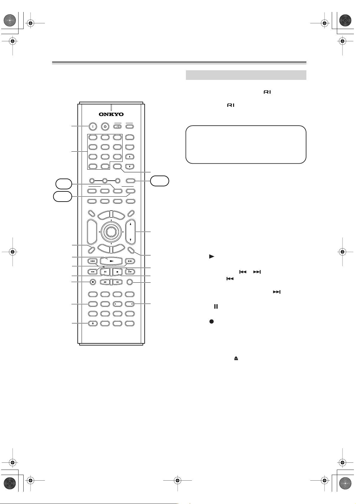
Remote Controller
■
■
■
How to Use the Remote Controller
Including the HT-R820THX, the remote controller can
be used to control up to 10 different components, including Onkyo components connected via . The remote
controller has a specific operating mode for use with
each type of component. Modes are selected by using the
nine REMOTE MODE buttons.
AMP/TUNER & TAPE Mode
TUNER/
TAPE
AMP
In AMP/TUNER & TAPE mode you can control the
HT-R820THX and an Onkyo cassette recorder connected via .
DVD, CD, MD & CDR Modes
REMOTE MODE
DVD
CD MD
With these modes you can control an Onkyo DVD
player, CD player, MiniDisc recorder, or CD recorder
connected via (the remote controller should be
pointed at the HT-R820THX). By entering the appropriate remote control code, the DVD mode can also be used
to control another manufacturer’s DVD player and the
[CD], [MD], and [CDR] mode buttons can also be used
with other manufacturer’s components (e.g., DVD, TV,
VCR, satellite or cable receiver). (See page 52.)
TV, VCR, CABLE & SAT Modes
With these modes you can control a TV, VCR, cable
receiver, and satellite receiver. You must enter the appropriate remote control code first (see page 52).
Use the REMOTE MODE—[AMP], [DVD],
1
[CD], [MD], [CDR], [TV], [VCR], [CABLE],
[SAT]— buttons to select the modes.
Uses the buttons supported by that mode
2
to control the component.
AMP/TUNER mode see page 12
DVD mode see page 14
CD mode see page 15
MD/ CDR mode see page 16
TAPE mode see page 17
TV mode see page 57
VCR/CABLE / SAT mode see page 57
CDR
SATTV VCR
CABLE
see page 17 for TV
control buttons
AMP/TUNER Mode
AMP/TUNER mode is used to control the
HT-R820THX. To select AMP/TUNER mode, press the
[AMP] mode button.
Remote
A
B
C
D
E
ON STANDBY
V1 V2 V3
123
DVD MULTI CH
456
CD
789
+
10 0
--/---
TONE
DVD
I
TAPE TUNER
CLEAR
_
+
REMOTE MODE
CD MD
T
V
INPUT
+
TV CH
-
V VOL
T
TUNER/
TAPE
AMP
CDR
indicator
This indicator
lights up when
the remote
controller is
transmitting
commands.
AMP/
TUNER
P
CABLE
M
E
N
U
E
D
I
U
G
P
U
T
E
S
RANDOM
ANGLE
LAST M
THX
STEREO
MEMORYA-BREPEAT
SEARCH
DSP
DSP
LEVEL -LEVEL
Re-EQ
L NIGHT
SAT
VOL
MUTING
+
Q
R
S
T
U
F
G
H
I
J
K
L
M
N
O
TV VCR
DIMMER SLEEP
TV
INPUT
CH
DISC
PREV
CH
DISPLAY
TEST TONE
OPEN/CLOSE
+
-
REC
SURR
U
N
E
M
P
O
T
ENTER
E
X
I
T
R
E
T
U
R
N
SP A SP B
SUBTITLEAUDIO
ALL ST
DIRECT
CH SEL
VIDEO OFF
OR-EQ
RC-571M
Note:
• Some of the functions described in this manual may
not work as expected with other components.
12

HT-S870_En.book Page 13 Monday, September 13, 2004 5:15 PM
Remote Controller —Continued
For detailed information, refer to the pages in
parenthesis.
STANDBY button (33)
A
This button is used to set the HT-R820THX to
Standby.
B
ON button (33)
This button is used to turn on the HT-R820THX.
Input selector buttons (34)
C
These buttons are used to select the input sources.
D
MULTI CH button (35)
This button is used to select the multichannel DVD
input.
E
TONE, [–] & [+] buttons (38)
These buttons are used to adjust the bass and treble.
F
DIMMER button (38)
This button is used to adjust the display brightness.
G
Arrow [ ]/[ ]/[ ]/[ ] & ENTER button
This button is used to select and adjust settings.
CH +/– button (37)
H
This button is used to select radio presets.
RETURN button
I
This button is used to return to the previous screen
when changing settings.
DISPLAY button (35, 37)
J
This button is used to display various information
about the currently selected input source.
SP A & SP B buttons (34)
K
These buttons are used to turn on and off speaker
sets A and B.
Listening mode buttons (41)
L
SURR button
This button is used to select the Dolby and DTS listening modes.
ALL ST button
This button is used to select the All Ch Stereo listening mode.
THX button
This button is used to select the THX listening
mode.
STEREO button
This button is used to select the Stereo listening
mode.
DIRECT button
This button is used to select the Direct listening
mode.
[ DSP] & [DSP ] buttons
These buttons are used to select the Onkyo original
DSP (digital signal processor) listening modes.
M
TEST TONE, CH SEL, LEVEL- & LEVEL+
buttons (51)
These buttons are used to adjust the level of each
speaker individually.
OR-EQ button (38)
N
This button is used to turn on the OptiResponse
equalizer, which optimizes performance when the
HT-R820THX is used with the speakers included in
the HTP-820 Home Theater Speaker Package.
When the OptiResponse equalizer is on, you can
enjoy a powerful sound with movies or music.
L NIGHT button (46)
O
This button is used to set the Late Night function.
REMOTE MODE buttons (12)
P
These buttons are used to select the remote controller modes. When you use the remote controller, the
mode button for the currently selected mode lights
up.
Q
SLEEP button (39)
This button is used to set the Sleep function.
VOL button (34)
R
This button is used to set the volume of the
HT-R820THX.
SETUP button (46–51)
S
This button is used to access various settings.
MUTING button (39)
T
This button is used to mute the HT-R820THX.
U
Re-EQ button (46)
This button is used to turn on and off the Re-EQ
function.
13

HT-S870_En.book Page 14 Monday, September 13, 2004 5:15 PM
Remote Controller —Continued
1
2
DVD
3
4
5
6
7
A
B
C
4
5
6
7
8
9
J
K
L
M
N
O
P
ON STANDBY
V1 V2 V3
123
DVD MULTI CH
456
CD
TAPE TUNER
789
+
10 0
--/---
TONE
REMOTE MODE
DVD
CD MD
TV VCR
DIMMER SLEEP
TV
INPUT
PREV
CH
+
CH
DISC
-
DISPLAY
REC
SURR
TEST TONE
OPEN/CLOSE
P
O
T
R
E
T
SP A SP B
SUBTITLEAUDIO
ALL ST THX
DIRECT
CH SEL
VIDEO OFF
OR-EQ
_
U
N
E
M
ENTER
E
X
I
T
G
U
R
N
SEARCH
RC-571M
T
V
INPUT
I
+
TV CH
-
V VOL
T
CLEAR
TUNER/
TAPE
AMP
+
CDR
CABLE
SAT
M
E
N
U
VOL
E
D
I
U
P
U
T
E
S
MUTING
RANDOM
ANGLE
LAST M
STEREO
MEMORYA-BREPEAT
DSP
DSP
LEVEL -LEVEL
Re-EQ
L NIGHT
8
Q
CD
R
S
9
T
U
0
A
V
W
X
Y
Z
+
B
DVD Mode
DVD mode is used to control an Onkyo DVD player connected to the HT-R820THX via .
To set the remote controller to DVD mode, press the
[DVD] mode button.
Before selecting DVD mode and starting playback, you should press the [AMP] mode button
followed by the [DVD] input selector button to
select your DVD player as the input source.
STANDBY button
A
This button is used to set the DVD player to
Standby.
ON button
B
This button is used to turn on the DVD player and
set it to Standby.
Number buttons
C
These buttons are used to enter title, chapter, and
track numbers and to enter times for locating specific points in time.
TOP MENU button
D
This button is used to select a DVD’s top menu.
Arrow [ ]/[ ]/[ ]/[ ] & ENTER button
E
This button is used to navigate DVD menus and the
DVD player’s onscreen setup menus.
DISC +/– button
F
This button selects discs on a DVD changer.
RETURN/EXIT button
G
This button is used to exit the DVD player’s
onscreen setup menu and to restart menu playback.
DISPLAY button
H
This button is used to display information about the
current disc, title, chapter, or track on the DVD
player’s display, including the elapsed time, remaining time, total time, and so on.
I
Playback buttons
From left to right: Previous, Play, Next, Fast
Reverse, Pause, Stop, and Fast Forward.
J
Step & Slow [ ]/[ ] buttons
These buttons are used for frame-by-frame playback
and slow-motion playback.
K
AUDIO button
This button is used to select foreign language
soundtracks and audio formats (e.g., Dolby Digital
or DTS).
L
SUBTITLE button
This button is used to select subtitles.
M
REPEAT button
This button is used to set the repeat playback functions.
14

HT-S870_En.book Page 15 Monday, September 13, 2004 5:15 PM
Remote Controller —Continued
A-B button
N
This button is used to set the A–B repeat playback
function.
O
OPEN/CLOSE [ ] button
This button is used to open and close the disc tray.
P
VIDEO OFF button
This button is used to turn off the internal video circuitry, eliminating the possibility of interference
when playing audio-only discs.
Q
CLEAR button
This button is used to cancel functions and to clear
entered numbers.
R
MENU button
This button is used to display a DVD’s menu.
S
VOL button
This button is used to set the volume of the
HT-R820THX.
T
SETUP/GUIDE button
This button is used to access the DVD player’s
onscreen setup menus.
U
MUTING button
This button is used to mute the HT-R820THX.
RANDOM button
V
This button is used with the random playback function.
ANGLE button
W
This button is used to select different camera angles.
LAST M button
X
This button is used with the last memory function,
which allows you to resume DVD playback from
where you left off.
SEARCH button
Y
This button is used to search for titles, chapters,
tracks, and specific points in time.
MEMORY button
Z
This button is used with the memory playback function, which allows you to create a custom playlist of
titles, chapters, or tracks.
CD Mode
CD mode is used to control an Onkyo CD player connected to the HT-R820THX via .
To set the remote controller to CD mode, press the
[CD] mode button.
Before selecting CD mode and starting playback, you should press the [AMP] mode button
followed by the [CD] input selector button to
select your CD player as the input source.
ON button
1
This button is used to set the CD player to On or
Standby.
Number buttons
2
These buttons are used to enter track numbers and
to enter times for locating specific points in time.
3
DISC button
This button is used to select discs on a CD changer.
DISPLAY button
4
This button is used to display information about the
current disc or track on the CD player’s display,
including the elapsed time, remaining time, total
time, and so on.
5
Playback buttons
From left to right: Previous, Play, Next, Fast
Reverse, Pause, Stop, and Fast Forward.
REPEAT button
6
This button is used to set the repeat playback functions.
7
OPEN/CLOSE [ ] button
This button is used to open and close the disc tray.
8
CLEAR button
This button is used to cancel functions and to clear
entered numbers.
9
VOL button
This button is used to set the volume of the
HT-R820THX.
0
MUTING button
This button is used to mute the HT-R820THX.
A
RANDOM button
This button is used with the random playback function.
B MEMORY button
This button is used with the memory playback function, which allows you to create a custom playlist of
tracks.
15
HT-S870_En.book Page 16 Monday, September 13, 2004 5:15 PM
Remote Controller —Continued
MD
CDR
1
2
3
4
A
B
3
4
5
6
7
8
9
ON STANDBY
V1 V2 V3
123
DVD MULTI CH
456
CD
TAPE TUNER
789
+
10 0
--/---
TONE
_
REMOTE MODE
DVD
CD MD
TV VCR
DIMMER SLEEP
+
CH
DISC
-
REC
SURR
TEST TONE
E
M
P
O
T
E
X
R
E
T
U
SP A SP B
SUBTITLEAUDIO
ALL ST THX
DIRECT
CH SEL
VIDEO OFF
OR-EQ
RC-571M
TV
INPUT
PREV
CH
DISPLAY
OPEN/CLOSE
N
I
R
U
ENTER
T
N
V
T
I
TV CH
T
CLEAR
TUNER/
TAPE
+
CABLE
M
E
N
U
E
D
I
U
G
P
U
T
E
S
RANDOM
ANGLE
LAST M
STEREO
MEMORYA-BREPEAT
SEARCH
DSP
LEVEL -LEVEL
L NIGHT
INPUT
+
-
V VOL
AMP
CDR
SAT
VOL
MUTING
DSP
Re-EQ
J
TAPE
5
K
6
L
7
M
8
N
O
P
+
MD Mode & CDR Mode
MD mode is used to control an Onkyo MiniDisc recorder
connected to the HT-R820THX via . CDR mode is
used to control an Onkyo CD recorder connected to the
HT-R820THX via .
To select MD mode, press the [MD] mode button. To
select CDR mode, press the [CDR] mode button.
Before selecting MD or CDR mode and starting
playback, you should press the [AMP] mode
button followed by the [TAPE] input selector
button to select your MiniDisc or CD recorder
as the input source.
ON button
A
This button is used to set the MiniDisc recorder or
CD recorder to On or Standby.
Number buttons
B
These buttons are used to enter track numbers and
to enter times for locating specific points in time.
DISPLAY button
C
This button is used to display information about the
current disc or track on the MD/CDR recorder’s display, including the elapsed time, remaining time,
total time, and so on.
D
Play [ ] button
This button is used to start playback.
E
Previous & Next [ ]/[ ] buttons
The Previous [ ] button is used to select the previous track. During playback it selects the beginning of the current track. The Next [ ] button is
used to select the next track.
Pause [ ] button
F
This button is used to pause playback.
REC [ ] button
G
This button is used to start recording.
H
REPEAT button
This button is used to set the repeat playback functions.
OPEN/CLOSE [ ] button
I
This button is used to eject the MiniDisc or open
and close the disc tray of the CD recorder.
CLEAR button
J
This button is used to cancel functions and to clear
entered numbers.
VOL button
K
This button is used to set the volume of the
HT-R820THX.
MUTING button
L
This button is used to mute the HT-R820THX.
16

HT-S870_En.book Page 17 Monday, September 13, 2004 5:15 PM
Remote Controller —Continued
FR & FF [ ]/[ ] buttons
M
The FR [ ] button is used to start fast reverse. The
FF [ ] button is used to start fast forward.
N
Stop [ ] button
This button is used to stop playback.
RANDOM button
O
This button is used with the random playback function.
MEMORY button
P
This button is used with the memory playback function, which allows you to create a custom playlist of
tracks.
Tape Mode
Tape mode is used to control an Onkyo cassette recorder
connected to the HT-R820THX via .
To set the remote controller to Tape mode, press the
[AMP] mode button.
Before selecting TAPE mode and starting playback, you should press the [AMP] mode button
followed by the [TAPE] input selector button to
select your cassette recorder as the input
For double cassette decks, only Deck B can be controlled.
1
Play [ ] button
This button is used to start playback.
2
Previous & Next [ ]/[ ] buttons
The Previous [ ] button is used to select the previous track. During playback it selects the beginning of the current track. The Next [ ] button is
used to select the next track.
The Previous and Next [ ]/[ ] buttons may not
work properly with some cassette tapes depending
on how they were recorded.
3
Reverse Play [ ] button
This button is used to start reverse playback.
REC [ ] button
4
This button is used to start recording.
5
VOL button
This button is used to set the volume of the
HT-R820THX.
MUTING button
6
This button is used to mute the HT-R820THX.
7
Rewind & FF [ ]/[ ] buttons
The Rewind [ ] button is used to start rewind. The
FF [ ] button is used to start fast forward.
Stop [ ] button
8
This button is used to stop playback.
TV Control Buttons
The remote controller has dedicated buttons for controlling a TV, which can be used regardless of which remote
controller mode is currently selected. To use these buttons, you must first program the [TV] mode button with
the appropriate remote control code for your TV (see
page 52).
I
ON STANDBY
V1 V2 V3
123
DVD MULTI CH
456
CD
TAPE TUNER
789
+
10 0
--/---
TONE
_
REMOTE MODE
DVD
CD MD
TV VCR
DIMMER SLEEP
TV
INPUT
PREV
CH
DISPLAY
DISC
U
N
E
M
P
O
T
+
CH
ENTER
-
E
X
I
T
R
E
T
U
R
N
TV [ ]
TV CH [+]/[–]
[TV INPUT]
TV VOL [ ]/[ ]
V
T
INPUT
I
+
TV CH
-
T
V VOL
CLEAR
TUNER/
TAPE
AMP
+
CDR
SAT
CABLE
M
E
N
U
VOL
E
D
I
U
G
P
U
T
E
S
MUTING
Set the TV to On or Standby
Selects channels on the TV
Selects the TV’s VCR input
Adjusts the TV’s volume
TV
TV INPUT
TV CH
TV VOL
TV
You must enter the
appropriate remote
control code (see
page 52)
17
HT-S870_En.book Page 18 Monday, September 13, 2004 5:15 PM
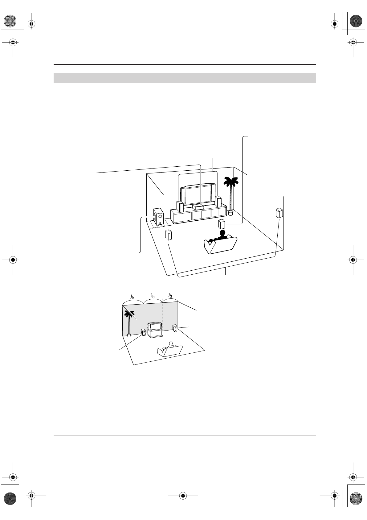
Connecting Speakers
Enjoying Home Theater
You can use two sets of speakers with the HT-R820THX: speaker set A and speaker set B.
Speaker set A (HTP-820) should be installed in your main listening room and can be used with THX, Dolby Digital
and DTS surround material.
Speaker set B can be installed in another room and used with stereo and mono material. Speakers can be positioned in
the standard position for stereo speakers or however you like.
Front left and right speakers
These output the overall sound. Their role in a home theater is to provide a solid
anchor for the sound image. They should be positioned facing the listener at
about ear level, and equidistant from the TV. Angle them inward so as to create
a triangle, with the listener at the apex.
Center speaker
This speaker enhances the front left
and right speakers, making sound
movements distinct and providing a
full sound image. In movies it’s used
mainly for dialog.
Position it close to your TV (preferably
on top) facing forward at about ear
level, or at the same height as the
front left and right speakers.
Subwoofer
The subwoofer handles the bass sounds of
the LFE (Low-Frequency Effects) channel.
The volume and quality of the bass output
from your subwoofer will depend on its position, the shape of your listening room, and
your listening position. In
general, a good bass sound
can be obtained by installing the subwoofer in a front
corner, or at one-third the
width of the wall, as shown.
If the subwoofer is situated
close to a wall, rack, etc.,
leave a gap of at least 6
inches (15 cm).
1/3 room
length
Corner
Surround left and right speakers
These speakers are used for precise sound
positioning and to add realistic ambience.
Position them at the sides of the listener, or
slightly behind, about 2–3 feet (60–100 cm)
above ear level. Ideally they should be equidistant from the listener.
Wall-mounting the surround speakers
If the surround speakers are to be wallmounted, make sure that the walls are
strong enough to support the speaker’s
weight. The weight that mounting screws
can support varies greatly depending on the
wall material and the position of the reinforcing ribs embedded in the wall.
Use long screws with a head diameter of
1/4 inch (6.3 mm) or less and a shank diameter of 1/8 inch (3.5 mm) or less. (We recommend that you consult a home
installation professional.)
Surround back speaker
This speaker further enhances
the realism of surround sound
and improves sound localization behind the listener. Position it behind the listener about
2–3 feet (60–100 cm) above
ear level. Make sure that the
listening position is within the
range of the speaker.
Speaker Configuration
To get the very best from your surround-sound system, you should also specify the distance between the listener and
each individual speaker so that the sound from each speaker arrives at the listener’s ears at the same time (see page 48).
In addition, you should set the level of each individual speaker to achieve an equal balance (see page 49.)
18
HT-S870_En.book Page 19 Monday, September 13, 2004 5:15 PM
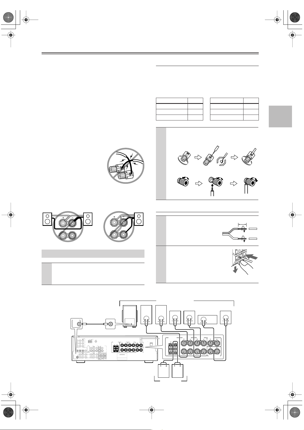
Connecting Speakers —Continued
Before you connect the supplied speakers, read the following:
• Disconnect the power cord from the wall outlet.
•Pay close attention to speaker wiring polarity. In other
words, connect positive (+) terminals only to positive (+)
terminals, and negative (–) terminals only to negative (–)
terminals. If you get them the wrong way around, the
sound will be out of phase and will sound odd.
• Only use speakers with an impedance of 8 ohms or
higher. If you use speakers with a lower impedance,
and use the amplifier at high volume levels for a long
period of time, the built-in protection circuit may be
activated.
• Unnecessarily long or very thin speaker cables may
affect the sound quality and should be avoided.
• Be careful not to short the positive and negative connections.
Doing so may damage the
HT-R820THX.
• Don’t connect more than one
cable to each speaker terminal.
Doing so may damage the
HT-R820THX.
• If you want to connect a single speaker instead of a
pair, connect it to either the left or right speaker terminals, not both.
Connecting speaker Set A
The HT-R820THX’s positive (+) speaker terminals and
speaker’s positive (+) terminals are color-coded for ease
of identification. (The negative (–) speaker terminals are
all black.) Match the color of each cables to the corresponding apeaker terminal.
Speaker terminal Color Speaker terminal Color
Front left White Surround left Blue
Front right Red Surround right Gray
Center Green Surround back Brown
Unscrew the terminal. Fully insert the
1
wire. Screw the terminal tight.
• On the AV receiver
• On the speakers
When you Connecting Speaker Set B
Strip 3/8" (10 mm) of insula-
L
R
L
R
Connecting the Subwoofer
1
tion from the ends of the
speaker cables, and twist the
bare wires tightly, as shown.
While pressing the lever, insert
2
the wire into the hole, and then
release the lever.
Using the supplied RCA cable, connect
1
the subwoofer’s LINE INPUT to your
HT-R820THX’s SUBWOOFER PRE OUT.
Make sure that the terminals are
gripping the bare wires, not the
insulation.
The following illustration shows which speakers should be connected to which terminals.
Speaker set A (HTP-820)
Surround
Surround
right
FRONT
SPEAKERS A
L
R
left
speaker
SURROUND
SPEAKERS
L
R
SUBWOOFER
PRE OUT
VIDEO 1
IN
SUBWOOFER
PRE OUT
COMPONENT VIDEO
/2/3
DVD IN
DIGITAL IN
L
R
OPTICAL COAXIAL
IN
CD
Front
Powerd
Subwoofer
LINE INPUT
ANTENNA
FM
OUT
AM
75
Y
P
B
VIDEO 1
VIDEO 2
DVD MONITOR
P
R
123
IN IN
OUT
TAPE
OUT
IN
IN
IN
OUT
REMOTE
CONTROL
L
R
VIDEO 2
VIDEO
S VIDEO
OUT
IN
IN
SURR
CENTER
FRONT
L
R
SUB
VIDEO 1
WOOFER
DVD
Class 2 Wiring
FRONT
FRONT
SPEAKERS A
SPEAKERS B
L
L
R
RLR
AV RECEIVER
Front
right
speaker
CENTER
SPEAKER
SURROUND BACK
SPEAKER
AC OUTLET
AC 120 V 60 Hz
120
SWITCHED
W 1 A
MAX.
SURROUND
SPEAKERS
left
speaker
FRONT
SPEAKERS B
L
R
speaker
Center
speaker
CENTER
SPEAKER
SURROUND BACK
SPEAKER
Surround
back
speaker
3/8" (10 mm)
Front
right
speaker
Speaker set B
Front
left
speaker
(Sold separately)
19
HT-S870_En.book Page 20 Monday, September 13, 2004 5:15 PM
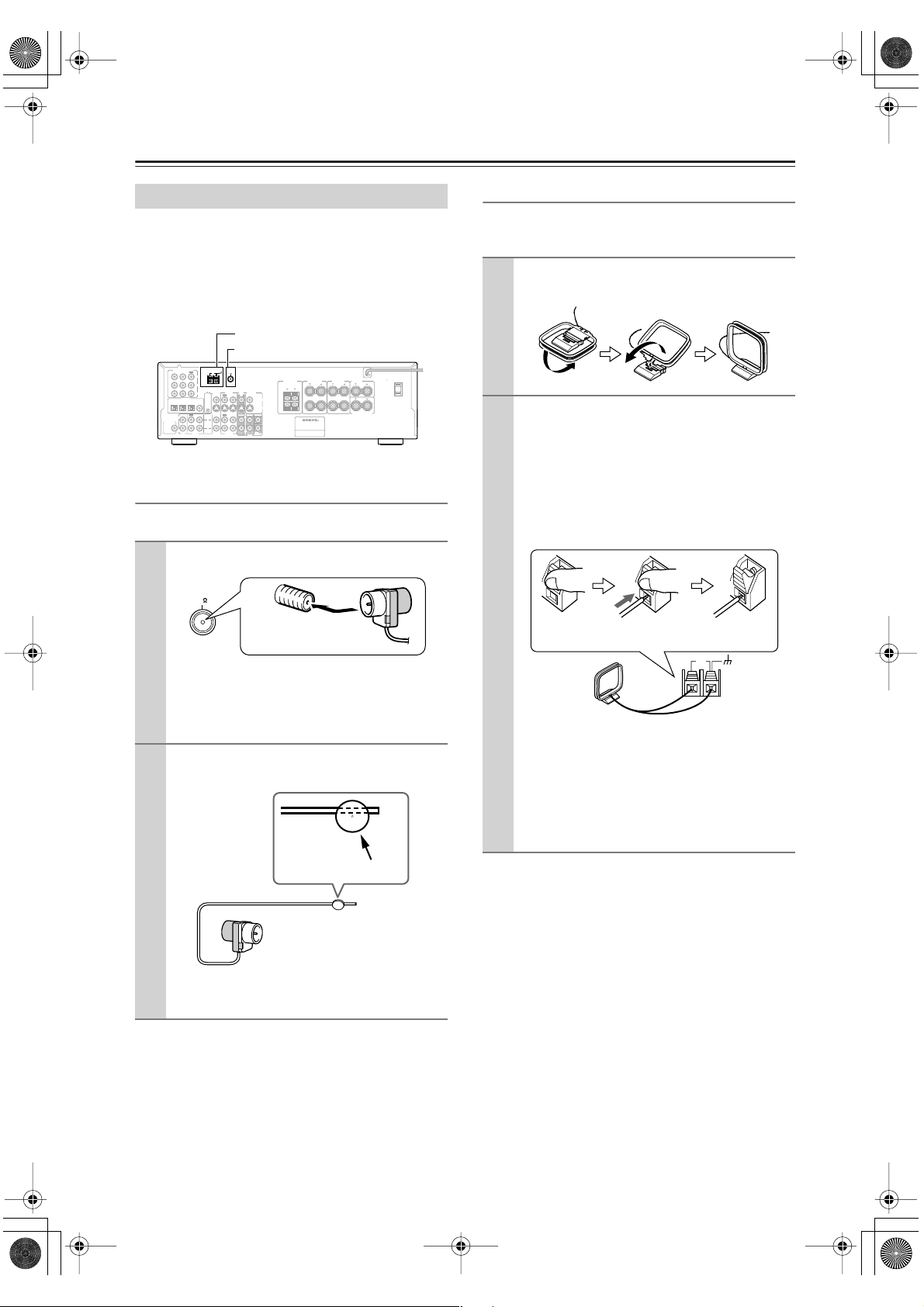
Connecting Antenna
Connecting Antenna
This chapter explains how to connect the supplied indoor
FM antenna and AM loop antenna and how to connect
commercially available outdoor FM and AM antennas.
The HT-R820THX won’t pick up any radio signals without any antenna connected, so you must connect the
antenna to use the tuner.
AM antenna push terminals
FM antenna socket
COMPONENT VIDEO
ANTENNA
OPTICAL COAXIAL
IN
FM
OUT
AM
75
Y
P
B
VIDEO 1
VIDEO 2
DVD MONITOR
PR
123
IN IN
OUT
TAPE
FM
75
OUT
IN
IN
IN
OUT
REMOTE
CONTROL
L
R
VIDEO 2
VIDEO
S VIDEO
OUT
IN
IN
SURR CENTER
FRONT
L
R
SUB
VIDEO 1
WOOFER
DVD
Class 2 Wiring
SURROUND
FRONT
FRONT
SPEAKERS B
L
R
SPEAKERS
SPEAKERS A
L
RLR
AV RECEIVER
CENTER
SPEAKER
SURROUND BACK
SPEAKER
AC OUTLET
AC 120 V 60 Hz
SWITCHED
W 1 A
MAX.
120
Insert the plug fully
into the socket.
VIDEO 1
/2/3
DVD IN
IN
DIGITAL IN
L
SUBWOOFER
PRE OUT
R
CD
Connecting the Indoor FM Antenna
The supplied indoor FM antenna is for indoor use only.
Attach the FM antenna, as shown.
1
Once the HT-R820THX is ready for use, you’ll
need to tune into an FM radio station and adjust
the position of the FM antenna to achieve the best
possible reception.
Use thumbtacks or something similar to
2
fix the FM antenna into position.
Connecting the AM Loop Antenna
The supplied indoor AM loop antenna is for indoor use
only.
Assemble the AM loop antenna, inserting
1
the tabs into the base, as shown.
Connect both wires of the AM loop
2
antenna to the AM push terminals, as
shown.
(The antenna’s wires are not polarity sensitive, so
they can be connected either way around.)
Make sure that the wires are attached securely and
that the push terminals are gripping the bare
wires, not the insulation.
Push Insert wire Release
AM
Once the HT-R820THX is ready for use, you’ll
need to tune into an AM radio station and adjust
the position of the AM antenna to achieve the best
possible reception.
Keep the antenna as far away as possible from the
HT-R820THX, TV, speaker cables, and power
cords.
Thumbtacks, etc.
Caution: Be careful that you don’t injure yourself
when using thumbtacks.
If you cannot achieve good reception with the supplied
indoor FM antenna, try a commercially available outdoor FM antenna instead (see page 21).
20
If you cannot achieve good reception with the supplied
indoor AM loop antenna, try using it with a commercially available outdoor AM antenna (see page 21).
 Loading...