


 Loading...
AV Receiver
HT-R548
Instruction Manual
Thank you for purchasing an Onkyo AV Receiver. Please read this manual thoroughly before making connections and plugging in the unit.
Following the instructions in this manual will enable you to obtain optimum performance and listening enjoyment from your new AV Receiver.
Please retain this manual for future reference.
Contents
Introduction ................................... |
2 |
Connections................................. |
10 |
Turning On & Basic Operations ......17
Advanced Operations ................. |
32 |
Controlling Other Components... |
42 |
Appendix ...................................... |
47 |
En
WARNING:
TO REDUCE THE RISK OF FIRE OR ELECTRIC SHOCK, DO NOT EXPOSE THIS APPARATUS TO RAIN OR MOISTURE.
CAUTION:
TO REDUCE THE RISK OF ELECTRIC SHOCK, DO NOT REMOVE COVER (OR BACK). NO USER-SERVICEABLE PARTS INSIDE. REFER SERVICING TO QUALIFIED SERVICE PERSONNEL.
WARNING |
|
AVIS |
RISK OF ELECTRIC SHOCK |
|
RISQUE DE CHOC ELECTRIQUE |
DO NOT OPEN |
|
NE PAS OUVRIR |
The lightning flash with arrowhead symbol, within an equilateral triangle, is intended to alert the user to the presence of uninsulated “dangerous voltage” within the product’s enclosure that may be of sufficient
magnitude to constitute a risk of electric shock to persons.
The exclamation point within an equilateral triangle is intended to alert the user to the presence of important operating and maintenance (servicing) instructions in the literature accompanying the appliance.
Important Safety Instructions
1.Read these instructions.
2.Keep these instructions.
3.Heed all warnings.
4.Follow all instructions.
5.Do not use this apparatus near water.
6.Clean only with dry cloth.
7.Do not block any ventilation openings. Install in accordance with the manufacturer’s instructions.
8.Do not install near any heat sources such as radiators, heat registers, stoves, or other apparatus (including amplifiers) that produce heat.
9.Do not defeat the safety purpose of the polarized or grounding-type plug. A polarized plug has two blades with one wider than the other. A grounding type plug has two blades and a third grounding prong. The wide blade or the third prong are provided for your safety. If the provided plug does not fit into your outlet, consult an electrician for replacement of the obsolete outlet.
10.Protect the power cord from being walked on or pinched particularly at plugs, convenience receptacles, and the point where they exit from the apparatus.
11.Only use attachments/accessories specified by the manufacturer.
12. Use only with the cart, stand, tripod, bracket, or table
specified by the manufacturer, or sold with the apparatus.
When a cart is used, use caution when moving the
cart/apparatus combination to
S3125A
avoid injury from tip-over.
13.Unplug this apparatus during lightning storms or when unused for long periods of time.
14.Refer all servicing to qualified service personnel. Servicing is required when the apparatus has been damaged in any way, such as power-supply cord or plug is damaged, liquid has been spilled or objects have fallen into the apparatus, the apparatus has been exposed to rain or moisture, does not operate normally, or has been dropped.
En
15.Damage Requiring Service
Unplug the apparatus from the wall outlet and refer servicing to qualified service personnel under the following conditions:
A.When the power-supply cord or plug is damaged,
B.If liquid has been spilled, or objects have fallen into the apparatus,
C.If the apparatus has been exposed to rain or water,
D.If the apparatus does not operate normally by following the operating instructions. Adjust only those controls that are covered by the operating instructions as an improper adjustment of other controls may result in damage and will often require extensive work by a qualified technician to restore the apparatus to its normal operation,
E.If the apparatus has been dropped or damaged in any way, and
F.When the apparatus exhibits a distinct change in performance this indicates a need for service.
16.Object and Liquid Entry
Never push objects of any kind into the apparatus through openings as they may touch dangerous voltage points or short-out parts that could result in a fire or electric shock.
The apparatus shall not be exposed to dripping or splashing and no objects filled with liquids, such as vases shall be placed on the apparatus.
Don’t put candles or other burning objects on top of this unit.
17.Batteries
Always consider the environmental issues and follow local regulations when disposing of batteries.
18.If you install the apparatus in a built-in installation, such as a bookcase or rack, ensure that there is adequate ventilation.
Leave 20 cm of free space at the top and sides and 10 cm at the rear. The rear edge of the shelf or board above the apparatus shall be set 10 cm away from the rear panel or wall, creating a flue-like gap for warm air to escape.
The temperature protection operates if the apparatus attain an abnormal high temperature.
The apparatus cannot operate until it has cooled down.
2

Precautions
1.Recording Copyright—Unless it’s for personal use only, recording copyrighted material is illegal without the permission of the copyright holder.
2.AC Fuse—The AC fuse inside the unit is not userserviceable. If you cannot turn on the unit, contact your Onkyo dealer.
3.Care—Occasionally you should dust the unit all over with a soft cloth. For stubborn stains, use a soft cloth dampened with a weak solution of mild detergent and water. Dry the unit immediately afterwards with a clean cloth. Don’t use abrasive cloths, thinners, alcohol, or other chemical solvents, because they may damage the finish or remove the panel lettering.
4.Power WARNING
BEFORE PLUGGING IN THE UNIT FOR THE FIRST TIME, READ THE FOLLOWING SECTION CAREFULLY.
AC outlet voltages vary from country to country. Make sure that the voltage in your area meets the voltage requirements printed on the unit’s rear panel (e.g., AC 230 V, 50 Hz or AC 120 V, 60 Hz).
The power cord plug is used to disconnect this unit from the AC power source. Make sure that the plug is readily operable (easily accessible) at all times.
Pressing the [ON/STANDBY] button to select Standby mode does not fully disconnect from the mains. If you do not intend to use the unit for an extended period, remove the power cord from the AC outlet.
5.Preventing Hearing Loss Caution
Excessive sound pressure from earphones and headphones can cause hearing loss.
6.Batteries and Heat Exposure Warning
Batteries (battery pack or batteries installed) shall not be exposed to excessive heat as sunshine, fire or the like.
7.Never Touch this Unit with Wet Hands—Never handle this unit or its power cord while your hands are wet or damp. If water or any other liquid gets inside this unit, have it checked by your Onkyo dealer.
8.Handling Notes
•If you need to transport this unit, use the original packaging to pack it how it was when you originally bought it.
•Do not leave rubber or plastic items on this unit for a long time, because they may leave marks on the case.
•This unit’s top and rear panels may get warm after prolonged use. This is normal.
•If you do not use this unit for a long time, it may not work properly the next time you turn it on, so be sure to use it occasionally.
For British models
Replacement and mounting of an AC plug on the power supply cord of this unit should be performed only by qualified service personnel.
IMPORTANT
The wires in the mains lead are coloured in accordance with the following code:
Blue: Neutral Brown: Live
As the colours of the wires in the mains lead of this apparatus may not correspond with the coloured markings identifying the terminals in your plug, proceed as follows: The wire which is coloured blue must be connected to the terminal which is marked with the letter N or coloured black.
The wire which is coloured brown must be connected to the terminal which is marked with the letter L or coloured red.
IMPORTANT
The plug is fitted with an appropriate fuse. If the fuse needs to be replaced, the replacement fuse must approved by ASTA or BSI to BS1362 and have the same ampere rating as that indicated on the plug. Check for the ASTA mark or the BSI mark on the body of the fuse.
If the power cord’s plug is not suitable for your socket outlets, cut it off and fit a suitable plug. Fit a suitable fuse in the plug.
For European Models
Declaration of Conformity
We, ONKYO EUROPE ELECTRONICS GmbH LIEGNITZERSTRASSE 6, 82194 GROEBENZELL, GERMANY
declare in own responsibility, that the ONKYO product described in this instruction manual is in compliance with the corresponding technical standards such as EN60065, EN55013, EN55020 and EN61000-3-2, -3-3.
GROEBENZELL, GERMANY
K. MIYAGI
ONKYO EUROPE ELECTRONICS GmbH
En
3
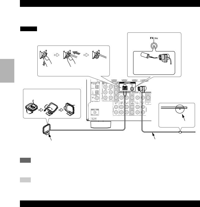
Supplied Accessories
Make sure you have the following accessories:
Indoor FM antenna ( page 16)
AM loop antenna ( page 16)
Speaker setup microphone ( page 23)
Remote controller (RC-799M) and two batteries (AA/R6) ( page 4)
*In catalogs and on packaging, the letter at the end of the product name indicates the color. Specifications and operations are the same regardless of color.
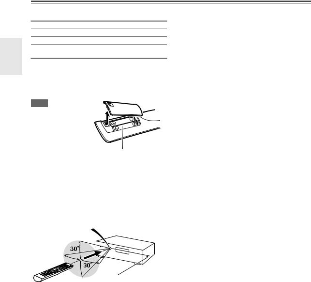
■Installing the batteries
Note
• If the remote controller doesn’t work reliably, try replacing the batteries.
•Don’t mix new and old batteries or different
types of batteries. |
Batteries (AA/R6) |
•If you intend not to use
the remote controller for a long time, remove the batteries to prevent damage from leakage or corrosion.
•Remove expired batteries as soon as possible to prevent damage from leakage or corrosion.
■Aiming the remote controller
To use the remote controller, point it at the AV receiver’s remote control sensor, as shown below.
Remote control sensor
AV receiver
 Approx. 5 m
En
4

Contents
Introduction |
|
Important Safety Instructions ......................................... |
2 |
Precautions....................................................................... |
3 |
Supplied Accessories...................................................... |
4 |
Features ............................................................................ |
6 |
Front & Rear Panels......................................................... |
7 |
Front Panel..................................................................... |
7 |
Display............................................................................ |
8 |
Rear Panel ..................................................................... |
8 |
Remote Controller............................................................ |
9 |
Controlling the AV Receiver ........................................... |
9 |
Controlling Other Components |
|
iPod/iPhone Playback via Onkyo Dock ........................ |
42 |
Using the Onkyo Dock.................................................. |
42 |
Controlling Your iPod/iPhone ....................................... |
42 |
Controlling Other Onkyo Components ........................ |
44 |
Preprogrammed Remote Control Codes ...................... |
44 |
Entering Remote Control Codes................................... |
44 |
Remote Control Codes for Onkyo Components |
|
Connected via u...................................................... |
44 |
Resetting REMOTE MODE Buttons ............................. |
45 |
Resetting the Remote Controller .................................. |
45 |
Controlling Other Components ..................................... |
45 |
Connections |
|
Connecting the AV Receiver ......................................... |
10 |
Connecting Your Speakers .......................................... |
10 |
About AV Connections ................................................. |
12 |
Connecting Components with HDMI ............................ |
13 |
Connecting Your Components ..................................... |
14 |
Connecting Onkyo u Components ............................ |
15 |
Connecting a Recording Component ........................... |
15 |
Connecting Antenna..................................................... |
16 |
Connecting the Power Cord ......................................... |
16 |
Turning On & Basic Operations |
|
Turning On/Off the AV Receiver ................................... |
17 |
Turning On ................................................................... |
17 |
Turning Off ................................................................... |
17 |
Playback.......................................................................... |
18 |
Playing the Connected Component.............................. |
18 |
Controlling Contents of USB Devices........................... |
18 |
Understanding Icons on the Display............................. |
19 |
Playing iPod/iPhone via USB ....................................... |
19 |
Playing USB Device ..................................................... |
20 |
Listening to AM/FM Radio ............................................ |
20 |
Using Basic Functions .................................................. |
23 |
Using the Automatic Speaker Setup ............................ |
23 |
Using the Listening Modes ........................................... |
26 |
Using the Home Menu.................................................. |
29 |
Selecting Speakers A and B......................................... |
29 |
Using the Sleep Timer.................................................. |
29 |
Setting the Display Brightness ..................................... |
30 |
Displaying Source Information ..................................... |
30 |
Changing the Input Display .......................................... |
30 |
Using the Music Optimizer ........................................... |
30 |
Muting the AV Receiver................................................ |
31 |
Using Headphones....................................................... |
31 |
Recording ..................................................................... |
31 |
Appendix |
|
Troubleshooting ............................................................. |
47 |
USB Features.................................................................. |
51 |
Connection Tips and Video Signal Path ...................... |
52 |
About HDMI..................................................................... |
53 |
Using an RIHD-compatible TV, Player, or Recorder ... |
54 |
Specifications ................................................................. |
56 |
To reset the AV receiver to its factory defaults, turn it on and, while holding down VCR/DVR, press
8ON/STANDBY ( page 47).
Advanced Operations |
|
Advanced Setup ............................................................. |
32 |
On-screen Setup Menus .............................................. |
32 |
Common Procedures in Setup Menu ........................... |
32 |
HDMI Input ................................................................... |
33 |
Component (Component Video Input).......................... |
33 |
Digital Audio (Digital Audio Input)................................. |
33 |
Sp Config (Speaker Configuration) .............................. |
34 |
Sp Distance (Speaker Distance) .................................. |
34 |
Level Cal (Level Calibration) ........................................ |
35 |
Audio Adjust ................................................................. |
35 |
Source Setup................................................................ |
36 |
Hardware...................................................................... |
38 |
HDMI Setup.................................................................. |
39 |
Using the Audio Settings .............................................. |
40 |
En
5
Features
Amplifier
•100 Watts/Channel @ 6 ohms (IEC)
•120 Watts/Channel @ 6 ohms (JEITA)
•Optimum Gain Volume Circuitry
•H.C.P.S. (High Current Power Supply) Massive High Power Transformer
Processing
•HDMI (Audio Return Channel, 3D, DeepColor, x.v.Color*1, Lip Sync, DTS*2-HD Master Audio, DTSHD High Resolution Audio, Dolby TrueHD*3, Dolby Digital Plus, DSD and Multi-CH PCM)
•Non-Scaling Configuration
•A-Form Listening Mode Memory
•Direct Mode
•Music Optimizer*4 for Compressed Digital Music files
•192 kHz/24-bit D/A Converters
•Powerful and Highly Accurate 32-bit Processing DSP
Connections
•4 HDMI*5 Inputs and 1 Output
•Onkyo pfor System Control
•3 Digital Inputs (2 Optical/1 Coaxial)
•Component Video Switching (2 Inputs/1 Output)
•Front-Panel USB Input for Memory Devices and iPod®/iPhone®*6 models
Miscellaneous
•40 FM/AM Presets
•Audyssey 2EQ®*7 to correct room acoustic problems
•Audyssey Dynamic EQ®*7 for loudness correction
•Audyssey Dynamic Volume®*7 to maintain optimal listening level and dynamic range
•Crossover Adjustment (40/50/60/70/80/90/100/120/150/200 Hz)
•A/V Sync Control Function (up to 400 ms)
•Auto Standby Function
•On-Screen Display via HDMI
*1 “x.v.Color” is a trademark of Sony Corporation.
*2
Manufactured under license under U.S. Patent #’s: 5,451,942; 5,956,674; 5,974,380; 5,978,762; 6,226,616; 6,487,535; 7,212,872; 7,333,929; 7,392,195; 7,272,567 & other U.S. and worldwide patents issued & pending. DTS and the Symbol are registered trademarks, & DTS-HD, DTS-HD Master Audio, and the DTS logos are trademarks of DTS, Inc. Product includes software.
© DTS, Inc. All Rights Reserved.
*3
Manufactured under license from Dolby Laboratories. Dolby, Pro Logic and the double-D symbol are trademarks of Dolby Laboratories.
*4 Music Optimizer™ is a trademark of Onkyo Corporation.
*5
“HDMI, the HDMI Logo, and High-Definition Multimedia Interface are trademarks or registered trademarks of HDMI Licensing LLC in the United States and other countries.”
*6
iPhone, iPod, iPod classic, iPod nano, iPod shuffle, and iPod touch are trademarks of Apple Inc., registered in the U.S. and other countries.
“Made for iPod” and “Made for iPhone” mean that an electronic accessory has been designed to connect specifically to iPod or iPhone, respectively, and has been certified by the developer to meet Apple performance standards. Apple is not responsible for the operation of this device or its compliance with safety and regulatory standards.
Please note that the use of this accessory with iPod or iPhone may affect wireless performance.
*7
Manufactured under license from Audyssey Laboratories™, Inc. U.S. and foreign patents pending. Audyssey 2EQ®, Audyssey Dynamic EQ® and Audyssey Dynamic Volume® are registered trademarks of Audyssey Laboratories, Inc.
En
6
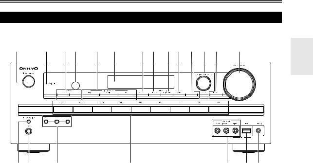
Front & Rear Panels
Front Panel
a b cd e f g h i j k l m n
o p q |
r |
s t u |
The page numbers in parentheses show where you can find the main explanation for each item.
a 8ON/STANDBY button (17)
b HDMI THRU indicator (39)
c SPEAKERS A and B buttons (29)
d Remote control sensor (4)
e LISTENING MODE buttons (26)
f Display (8)
g RT/PTY/TP button (21)
h MEMORY button (21)
i TUNING MODE button (20)
j DISPLAY button (30)
k SETUP button (32)
lTUNING, PRESET (20 to 21), arrow and ENTER buttons
m RETURN button
n MASTER VOLUME control (18)
o MUSIC OPTIMIZER button (30, 41) p PHONES jack (31)
q TONE and Tone Level buttons(40) r Input selector buttons (18)
s AUX INPUT AUDIO and VIDEO jacks (14, 31) t USB port (14)
u SETUP MIC jack (23)
En
7

Display |
|
|
|
|
|
|
a |
b |
c |
d |
e |
f |
g |
|
|
|
|
|
|
h |
|
|
|
|
|
|
i |
For detailed information, see the pages in parentheses.
a A and B speaker indicators (29) b Audio input indicators
c Listening mode and format indicators (26, 30)
dAudyssey indicator (23, 36) Dynamic EQ indicator (36) Dynamic Vol indicator (37)
e Tuning indicators (20)
f RDS indicator (21)
g SLEEP indicator (29)
hMUTING indicator (31) i Message area
Rear Panel
a |
|
|
|
b |
|
|
|
|
|
|
|
|
c d e |
|
|
|
|
|
|
|
|
|
|
|
|
|
|
f |
|
|||||||||||||||||||||||||||||||||||||||||||||||||||||||
|
|
|
|
|
|
|
|
|
|
|
|
|
|
|
|
|
|
|
|
|
|
|
|
|
|
|
|
|
|
|
|
|
|
|
|
|
|
|
|
|
|
|
|
|
|
|
|
|
|
|
|
|
|
|
|
|
|
|
|
|
|
|
|
|
|
|
|
|
|
|
|
|
|
|
|
|
|
|
|
|
|
|
|
|
|
|
|
|
|
|
|
|
|
|
|
|
|
|
|
|
|
|
|
|
|
|
|
|
|
|
|
|
|
|
|
|
|
|
|
|
|
|
|
|
|
|
|
|
|
|
|
|
|
|
|
|
|
|
|
|
|
|
|
|
|
|
|
|
|
|
|
|
|
|
|
|
|
|
|
|
|
|
|
|
|
|
|
|
|
|
|
|
|
|
|
|
|
|
|
|
|
|
|
|
|
|
|
|
|
|
|
|
|
|
|
|
|
|
|
|
|
|
|
|
|
|
|
|
|
|
|
|
|
|
|
|
|
|
|
|
|
|
|
|
|
|
|
|
|
|
|
|
|
|
|
|
|
|
|
|
|
|
|
|
|
|
|
|
|
|
|
|
|
|
|
|
|
|
|
|
|
|
|
|
|
|
|
|
|
|
|
|
|
|
|
|
|
|
|
|
|
|
|
|
|
|
|
|
|
|
|
|
|
|
|
|
|
|
|
|
|
|
|
|
|
|
|
|
|
|
|
|
|
|
|
|
|
|
|
|
|
|
|
|
|
|
|
|
|
|
|
|
|
|
|
|
|
|
|
|
|
|
|
|
|
|
|
|
|
|
|
|
|
|
|
|
|
|
|
|
|
|
|
|
|
|
|
|
|
|
|
|
|
|
|
|
|
|
|
|
|
|
|
|
|
|
|
|
|
|
|
|
|
|
|
|
|
|
|
|
|
|
|
|
|
|
|
|
|
|
|
|
|
|
|
|
|
|
|
|
|
|
|
|
|
|
|
|
|
|
|
|
|
|
|
|
|
|
|
|
|
|
|
|
|
|
|
|
|
|
|
|
|
|
|
|
|
|
|
|
|
|
|
|
|
|
|
|
|
|
|
|
|
|
|
|
|
|
|
|
|
|
|
|
|
|
|
|
|
|
|
|
|
|
|
|
|
|
|
|
|
|
|
|
|
|
|
|
|
|
|
|
|
|
|
|
|
|
|
|
|
|
|
|
|
|
|
|
|
|
|
|
|
|
|
|
|
|
|
|
|
|
|
|
|
|
|
|
|
|
|
|
|
|
|
|
|
|
|
|
|
|
|
|
|
|
|
|
|
|
|
|
|
|
|
|
|
|
|
|
|
|
|
|
|
|
|
|
|
|
|
|
|
|
|
|
|
|
|
|
|
|
|
|
|
|
|
|
|
|
|
|
|
|
|
|
|
|
|
|
|
|
|
|
|
|
|
|
|
|
|
|
|
|
|
|
|
|
|
|
|
|
|
|
|
|
|
|
|
|
|
|
|
|
|
|
|
|
|
|
|
|
|
|
|
|
|
|
|
|
|
|
|
|
|
|
|
|
|
|
|
|
|
|
|
|
|
|
|
|
|
|
|
|
|
|
|
|
|
|
|
|
|
|
|
|
|
|
|
|
|
|
|
|
|
|
|
|
|
|
|
|
|
|
|
|
|
|
|
|
|
|
|
|
|
|
|
|
|
|
|
|
|
|
|
|
|
|
|
|
|
|
|
|
|
|
|
|
|
|
|
|
|
|
|
|
|
|
|
|
|
|
|
|
|
|
|
|
|
|
|
|
|
|
|
|
|
|
|
|
|
|
|
|
|
|
|
|
|
|
|
|
|
|
|
|
|
|
|
|
|
|
|
|
|
|
|
|
|
|
|
|
|
|
|
|
|
|
|
|
|
|
|
|
|
|
|
|
|
|
|
|
|
|
|
|
|
|
|
|
|
|
|
|
|
|
|
|
|
|
|
|
|
|
|
|
|
|
|
|
|
|
|
|
|
|
|
|
|
|
|
|
|
|
|
|
|
|
|
|
|
|
|
|
|
|
|
|
|
|
|
|
|
|
|
|
|
|
|
|
|
|
|
|
|
|
|
|
|
|
|
|
|
|
|
|
|
|
|
|
|
|
|
|
|
|
|
|
|
|
|
|
|
|
|
|
|
|
|
|
|
|
|
|
|
|
|
|
|
|
|
|
|
|
|
|
|
|
|
|
|
|
|
|
|
|
|
|
|
|
|
|
|
|
|
|
|
|
|
|
|
|
|
|
|
|
|
|
|
|
|
|
|
|
|
|
|
|
|
|
|
|
|
|
|
|
|
|
|
|
|
|
|
|
|
|
|
|
|
|
|
|
|
|
|
|
|
|
|
|
|
|
|
|
|
|
|
|
|
|
|
|
|
|
|
|
|
|
|
|
|
|
|
|
|
|
|
|
|
|
|
|
|
|
|
|
|
|
|
|
|
|
|
|
|
|
|
|
|
|
|
|
|
|
|
|
|
|
|
|
|
|
|
|
|
|
|
|
|
|
|
|
|
|
|
|
|
|
|
|
|
|
|
|
|
|
|
|
|
|
|
|
|
|
|
|
|
|
|
|
|
|
|
|
|
|
|
|
|
|
|
|
|
|
|
|
|
|
|
|
|
|
|
|
|
|
|
|
|
|
|
|
|
|
|
|
|
|
|
|
|
|
|
|
|
|
|
|
|
|
|
|
|
|
|
|
|
|
|
|
|
|
|
|
|
|
|
|
|
|
|
|
|
|
|
|
|
|
|
|
|
|
|
|
|
|
|
|
|
|
|
|
|
|
|
|
|
|
|
|
|
|
|
|
|
|
|
|
|
|
|
|
|
|
|
|
|
|
|
|
|
|
|
|
|
|
|
|
|
|
|
|
|
|
|
|
|
|
|
|
|
|
|
|
|
|
|
|
|
|
|
|
|
|
|
|
|
|
|
|
|
|
|
|
|
|
|
|
|
|
|
|
|
|
|
|
|
|
|
|
|
|
|
|
|
|
|
|
|
|
|
|
|
|
|
|
|
|
|
|
|
|
|
|
|
|
|
|
|
|
|
|
|
|
|
|
|
|
|
|
|
|
|
|
|
|
|
|
|
|
|
|
|
|
|
|
|
|
|
|
|
|
|
|
|
|
|
|
|
|
|
|
|
|
|
|
|
|
|
|
|
|
|
|
|
|
|
|
|
|
|
|
|
|
|
|
|
|
|
|
|
|
|
|
|
|
|
|
|
|
|
|
|
|
|
|
|
|
|
|
|
|
|
|
|
|
|
|
|
|
|
|
|
|
|
|
|
|
|
|
|
|
|
|
|
|
|
|
|
|
|
|
|
|
|
|
|
|
|
|
|
|
|
|
|
|
|
|
|
|
|
|
|
|
|
|
|
|
|
|
|
|
|
|
|
|
|
|
|
|
|
|
|
|
|
|
|
|
|
|
|
|
|
|
|
|
|
|
|
|
|
|
|
|
|
|
|
|
|
|
|
|
|
|
|
|
|
|
|
|
|
|
|
|
|
|
|
|
|
|
|
|
|
|
|
|
|
|
|
|
|
|
|
|
|
|
|
|
|
|
|
|
|
|
|
|
|
|
|
|
|
|
|
|
|
|
|
|
|
|
|
|
|
|
|
|
|
|
|
|
|
|
|
|
|
|
|
|
|
|
|
|
|
|
|
|
|
|
|
|
|
|
|
|
|
|
|
|
|
|
|
|
|
|
|
|
|
|
|
|
|
|
|
|
|
|
|
|
|
|
|
|
|
|
|
|
|
|
|
|
|
|
|
|
|
|
|
|
|
|
|
|
|
|
|
|
|
|
|
|
|
|
|
|
|
|
|
|
|
|
|
|
|
|
|
|
|
|
|
|
|
|
|
|
|
|
|
|
|
|
|
|
|
|
|
|
|
|
|
|
|
|
|
|
|
|
|
|
|
|
|
|
|
|
|
|
|
|
|
|
|
|
|
|
|
|
|
|
|
|
|
|
|
|
|
|
|
|
|
|
|
|
|
|
|
|
|
|
|
|
|
|
|
|
g h i j
a DIGITAL IN COAXIAL and OPTICAL jacks b HDMI IN and OUT jacks
c FM ANTENNA jack and AM ANTENNA terminal d SUBWOOFER PRE OUT jack
eSPEAKERS terminals
(FRONT A, CENTER, SURROUND, FRONT B)
f Power cord
g u REMOTE CONTROL jack
h COMPONENT VIDEO IN and OUT jacks
iComposite video and analog audio jacks (BD/DVD IN, VCR/DVR IN and OUT, CBL/SAT IN, GAME IN, TV/CD IN)
j MONITOR OUT V jack
See “Connecting the AV Receiver” for connection ( pages 10 to 16).
En
8

Remote Controller
Controlling the AV Receiver
a |
i |
|
c |
||
|
||
b |
|
|
|
j |
|
c |
|
|
|
k |


 d d
d d


e a
f |
l |
m
g


|
e |
|
h |
n |
|
b |
||
|
To control the AV receiver, press RECEIVER to select Receiver mode.
You can also use the remote controller to control Onkyo Blu-ray Disc/DVD player, CD player, and other components.
See “Entering Remote Control Codes” for more details ( page 44).
For detailed information, see the pages in parentheses.
a 8button (17)
bREMOTE MODE/INPUT SELECTOR buttons (18, 44 to 45)
c TONE and Tone Level buttons (40) d SP A/B button (29)
e Arrow q/w/e/rand ENTER buttons f SETUP button (32)
g LISTENING MODE buttons (26)
hDIMMER button (30) i DISPLAY button (30)
j MUTING button (31) k VOL q/wbutton (18) l RETURN button
m HOME button (29) n SLEEP button (29)
Controlling the tuner
To control the AV receiver’s tuner, press AM or FM.
a Arrow q/wbuttons (20)
b D.TUN button (21)
c DISPLAY button (21)
d CH +/– button (21)
e Number buttons (21)
En
9

Connecting the AV Receiver
Connecting Your Speakers
Connecting the Speaker Cables
The following illustration shows which speaker should be connected to each pair of terminals.
|
|
|
|
|
|
|
|
|
|
|
|
|
|
|
|
|
|
|
|
|
|
|
|
|
|
|
|
|
|
|
|
|
|
|
|
|
|
|
|
|
|
|
|
|
|
|
|
|
|
|
|
|
|
|
|
|
|
|
|
|
|
|
|
|
|
|
|
|
|
|
|
|
|
|
|
|
|
|
|
|
|
|
|
|
|
|
|
|
|
|
|
|
|
|
|
|
|
|
|
|
|
|
|
|
|
|
|
|
|
|
|
|
|
|
|
|
|
|
|
|
|
|
|
|
|
|
|
|
|
|
|
|
|
|
|
|
|
|
|
|
|
|
|
|
|
|
|
|
|
|
|
|
|
|
|
|
|
|
|
|
|
|
|
|
|
|
|
|
|
|
|
|
|
|
|
|
|
|
|
|
|
|
|
|
|
|
|
|
|
|
|
|
|
|
|
|
|
|
|
|
|
|
|
|
|
|
|
|
|
|
|
|
|
|
|
|
|
|
|
|
|
|
|
|
|
|
|
|
|
|
|
|
|
|
|
|
|
|
|
|
|
|
|
|
|
|
|
|
|
|
|
|
|
|
|
|
|
|
|
|
|
|
|
|
|
|
|
|
|
|
|
|
|
|
|
|
|
|
|
|
|
|
|
|
|
|
|
|
|
|
|
|
|
|
|
|
|
|
|
|
|
|
|
|
|
|
|
|
|
|
|
|
|
|
|
|
|
|
|
|
|
|
|
|
|
|
|
|
|
|
|
|
|
|
|
|
|
|
|
|
|
|
|
|
|
|
|
|
|
|
|
|
|
|
|
|
|
|
|
|
|
|
|
|
|
|
|
|
|
|
|
|
|
|
|
|
|
|
|
|
|
|
|
|
|
|
|
|
|
|
|
|
|
|
|
|
|
|
|
|
|
|
|
|
|
|
|
|
|
|
|
|
|
|
|
|
|
|
|
|
|
|
|
|
|
|
|
|
|
|
|
|
|
|
|
|
|
|
|
|
|
|
|
|
|
|
|
|
|
|
|
|
|
|
|
|
|
|
|
|
|
|
|
|
|
|
|
|
|
|
|
|
|
|
|
|
|
|
|
|
|
|
|
|
|
|
|
|
|
|
|
|
|
|
|
|
|
|
|
|
|
|
|
|
|
|
|
|
|
|
|
|
|
|
|
|
|
|
|
|
|
|
|
|
|
|
|
|
|
|
|
|
|
|
|
|
|
|
|
|
|
|
|
|
|
|
|
|
|
|
|
|
|
|
|
|
|
|
|
|
|
|
|
|
|
|
|
|
|
|
|
|
|
|
|
|
|
|
|
|
|
|
|
|
|
|
|
|
|
|
|
|
|
|
|
|
|
|
|
|
|
|
|
|
|
|
|
|
|
|
|
|
|
|
|
|
|
|
|
|
|
|
|
|
|
|
|
|
|
|
|
|
|
|
|
|
|
|
|
|
|
|
|
|
|
|
|
|
|
|
|
|
|
|
|
|
|
|
|
|
|
|
|
|
|
|
|
|
|
|
|
|
|
|
|
|
|
|
|
|
|
|
|
|
|
|
|
|
|
|
|
|
|
|
|
|
|
|
|
|
|
|
|
|
|
|
|
|
|
|
|
|
|
|
|
|
|
|
|
|
|
|
|
|
|
|
|
|
|
|
|
|
|
|
|
|
|
|
|
|
|
|
|
|
|
|
|
|
|
|
|
|
|
|
|
|
|
|
|
|
|
|
|
|
|
|
|
|
|
|
|
|
|
|
|
|
|
|
|
|
|
|
|
|
|
|
|
|
|
|
|
|
|
|
|
|
|
|
|
|
|
|
|
|
|
|
|
|
|
|
|
|
|
|
|
|
|
|
|
|
|
|
|
|
|
|
|
|
|
|
|
|
|
|
|
|
|
|
|
|
|
|
|
|
|
|
|
|
|
|
|
|
|
|
|
|
|
|
|
|
|
|
|
|
|
|
|
|
|
|
|
|
|
|
|
|
|
|
|
|
|
|
|
|
|
|
|
|
|
|
|
|
|
|
|
|
|
|
|
|
|
|
|
|
|
|
|
|
|
|
|
|
|
|
|
|
|
|
|
|
|
|
|
|
|
|
|
|
|
|
|
|
|
|
|
|
|
|
|
|
|
|
|
|
|
|
|
|
|
|
|
|
|
|
|
|
|
|
|
|
|
|
|
|
|
|
|
|
|
|
|
|
|
|
|
|
|
|
|
|
|
|
|
|
|
|
|
|
|
|
|
|
|
|
|
|
|
|
|
|
|
|
|
|
|
|
|
|
|
|
|
|
|
|
|
|
|
|
|
|
|
|
|
|
|
|
|
|
|
|
|
|
|
|
|
|
|
|
|
|
|
|
|
|
|
|
|
|
|
|
|
|
|
|
|
|
|
|
|
|
|
|
|
|
|
|
|
|
|
|
|
|
|
|
|
|
|
|
|
|
|
|
|
|
|
|
|
Front B right |
|
|
|
|
Front B left |
|
|
|
|
|
|||||||||||||||||||||
Speakers B
|
Surround |
Surround |
|
right |
left |
Front A right |
Center |
Front A left |
|
Speakers A |
|
■Push-type speaker terminals |
|
|
|
|
|
|
|
|
Strip 10 to 12 mm of insulation from the ends of the speaker cables, |
10 to 12 mm |
|
||||||
and twist the bare wires tightly, as shown. |
|
|
|
|
|
|
|
|
|
|
|
|
|
|
|
|
|
|
|
|
|
|
|
|
|
|
En
10
Speaker Configuration
The following table indicates the channels you should use depending on the number of speakers that you have.
No matter how many speakers you use, a powered subwoofer is recommended for a really powerful and solid bass.
To get the best from your surround sound system, you need to set the speaker settings manually ( page 34).
Number of channels |
2 |
3 |
4 |
5 |
Front speakers |
|
|
|
|
|
|
|
|
|
Center speaker |
|
|
|
|
|
|
|
|
|
Surround speakers |
|
|
|
|
|
|
|
|
|
Connecting the Speaker Cables
The speaker terminals are color-coded for identification purpose.
Speaker |
Color |
Front left |
White |
|
|
Front right |
Red |
|
|
Center |
Green |
|
|
Surround left |
Blue |
|
|
Surround right |
Gray |
|
|
Speaker Connection Precautions
Read the following before connecting your speakers:
•You can connect speakers with an impedance of between 6 and 16 ohms. If you use speakers with a lower impedance, and use the amplifier at high volume levels for a long period of time, the built-in amp protection circuit may be activated.
•Disconnect the power cord from the wall outlet before making any connections.
•Read the instructions supplied with your speakers.
•Pay close attention to speaker wiring polarity. In other words, connect positive (+) terminals only to positive (+) terminals, and negative (–) terminals only to negative (–) terminals. If you get them the wrong way around, the sound will be out of phase and will sound unnatural.
•Unnecessarily long, or very thin speaker cables may affect the sound quality and should be avoided.
•Be careful not to short the positive and negative wires. Doing so may damage the AV receiver.
•Make sure the metal core of the wire does not have contact with the AV receiver’s rear panel. Doing so may damage the AV receiver.
•Don’t connect more than one cable to each speaker terminal. Doing so may damage the AV receiver.
•Don’t connect one speaker to several terminals.
Using a Powered Subwoofer
To find the best position for your subwoofer, while playing a movie or some music with good bass, experiment by placing your subwoofer at various positions within the room, and choose the one that provides the most satisfying results.
Tip
•If your subwoofer is unpowered and you’re using an external amplifier, connect the subwoofer pre out jack to an input on the amplifier.
LINE INPUT
LINE INPUT
Powered subwoofer
Corner position
1/3 of wall position
En
11
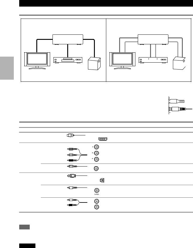
About AV Connections
Connecting AV components
HDMI cable |
|
: Video & Audio |
|
AV receiver |
|
Blu-ray Disc/ |
|
TV, projector, etc. |
DVD player |
Game console |
Other cables |
|
: Video |
|
||
|
|
: Audio |
|
|
AV receiver |
|
|
|
|
|
|
|
|
|
|
|
|
|
|
|
|
|
|
|
|
|
|
|
|
|
|
|
|
|
|
|
|
|
|
|
|
|
Blu-ray Disc/ |
|
|
|
|||||||
|
|
|
|
||||||||
TV, projector, etc. |
Game console |
||||||||||
DVD player |
|||||||||||
•Before making any AV connections, read the manuals supplied with your AV components.
•Don’t connect the power cord until you’ve completed and double-checked all AV connections.
• Push plugs in all the way to make good connections (loose connections can cause noise or |
|
|
|
|
|
Right! |
|
||
malfunctions). |
|
|
|
|
|
|
|
|
|
• To prevent interference, keep audio and video cables away from power cords and speaker cables.
 Wrong!
AV Cables and Jacks
Signal |
Cable |
Jack |
|
Description |
Video and |
HDMI |
|
HDMI |
HDMI connections can carry digital video and audio. |
Audio |
|
|
|
|
|
|
|
|
Video |
Component video |
Y |
|
|
|
|
|
PB |
|
|
PR |
Green
Component video separates the luminance (Y) and color
difference signals (PB, PR), providing the best picture Blue quality (some TV manufacturers label their component
video sockets slightly differently).
Red
Composite video |
Yellow |
Composite video is commonly used on TVs, VCRs, and |
V |
other video equipment. |
|
|
|
Audio |
Optical digital |
|
audio |
OPTICAL |
Optical digital connections allow you to enjoy digital |
||
|
|
|
sound such as PCM*, Dolby Digital or DTS. The audio |
|
|
|
|
|
|
|
quality is the same as coaxial. |
|
|
|
|
Coaxial digital |
Coaxial digital connections allow you to enjoy digital |
audio |
Orange sound such as PCM*, Dolby Digital or DTS. The audio |
|
quality is the same as optical. |
Analog audio (RCA)
L
R
White |
Analog audio connections (RCA) carry analog audio. |
|
|
Red |
|
*Available sampling rate for PCM input signal is 32/44.1/48/88.2/96 kHz. Even 176.4/192 kHz is effective in case of the HDMI connection.
Note
•The AV receiver does not support SCART plugs.
•The AV receiver’s optical digital jacks have shutter-type covers that open when an optical plug is inserted and close when it’s removed. Push plugs in all the way.
Caution
•To prevent shutter damage, hold the optical plug straight when inserting and removing.
En
12
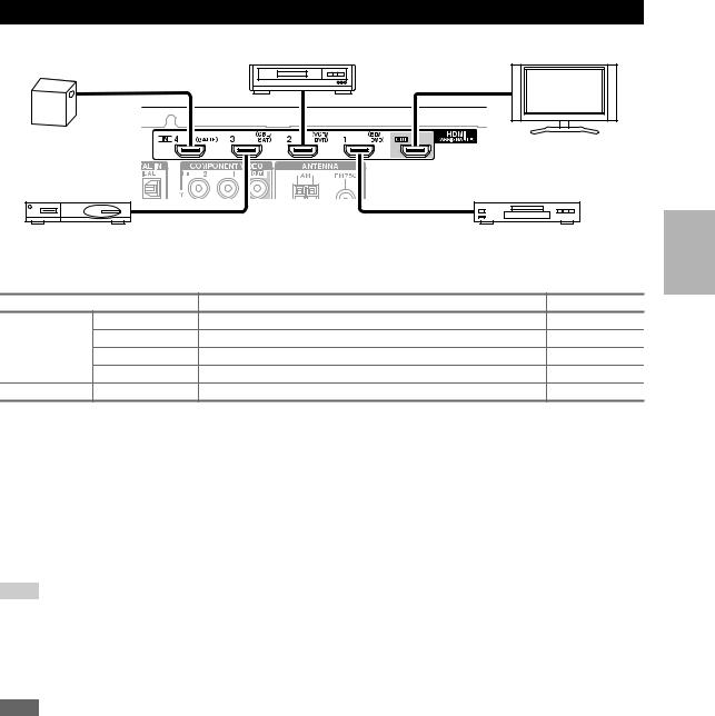
Connecting Components with HDMI
VCR or DVD recorder/Digital Video Recorder
Game console |
TV, projector, etc. |
|
Satellite/cable set-top box, etc. Blu-ray Disc/DVD player
Connect your components to the appropriate jacks. The default input assignments are shown below.
: Assignment can be changed ( page 33).
Jack |
|
Components |
Assignable |
Input |
HDMI IN1 |
Blu-ray Disc/DVD player |
|
|
HDMI IN2 |
VCR or DVD recorder/Digital Video Recorder |
|
|
HDMI IN3 |
Satellite/cable set-top box, etc. |
|
|
HDMI IN4 |
Game console |
|
Output |
HDMI OUT |
TV, projector, etc. |
|
See also:
•“Connection Tips and Video Signal Path” ( page 52)
•“About HDMI” ( page 53)
•“Using an RIHD-compatible TV, Player, or Recorder” ( page 54)
Audio return channel (ARC) function
Audio return channel (ARC) function enables an HDMI capable TV to send the audio stream to the HDMI OUT of the AV receiver ( page 40).
•To use ARC function, you must select the TV/CD input selector, your TV must support ARC function and “HDMI Ctrl(RIHD)” is set to “On” ( page 39).
Tip
•To listen to audio received by the HDMI IN jacks through your TV’s speakers:
–Set the “HDMI Ctrl(RIHD)” setting to “On” for an p-compatible TV.
–Set the “Audio TV Out” setting to “On” ( page 39) when the TV is not compatible with por the “HDMI Ctrl(RIHD)” setting to “Off”.
–Set your Blu-ray Disc/DVD player’s HDMI audio output setting to PCM.
–To listen to TV audio through the AV receiver, see “Connecting Your Components” ( page 14).
Note
•When listening to an HDMI component through the AV receiver, set the HDMI component so that its video can be seen on the TV screen (on the TV, select the input of the HDMI component connected to the AV receiver). If the TV power is off or the TV is set to another input source, this may result in no sound from the AV receiver or the sound may be cut off.
•When the “Audio TV Out” setting is set to “On” ( page 39) to hear from your TV’s speakers, by controlling the AV receiver’s volume, the sound will be output from the AV receiver’s speakers, too. When the “HDMI Ctrl(RIHD)” setting is set to “On”
( page 39) to hear from speakers of p-compatible TV, by controlling the AV receiver’s volume, the AV receiver’s speakers will produce sound while the TV’s speakers are muted. To stop the AV receiver’s speakers producing sound, change the settings, change your TV’s settings, or turn down the AV receiver’s volume.
En
13
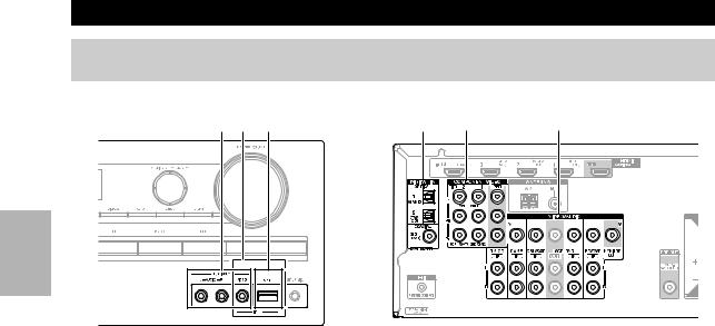
Connecting Your Components
The on-screen setup menus appear only on a TV that is connected to the HDMI OUT. If your TV is connected to the MONITOR OUT V or the COMPONENT VIDEO OUT, use the AV receiver’s display when changing settings.
A B C D E F
Connect your components to the appropriate jacks. The default input assignments are shown below.
|
|
|
|
|
|
: Assignment can be changed ( page 33). |
|
|
|
|
|
|
|
||
No. |
Jack |
|
|
Components |
Assignable |
||
|
|
|
|
|
|
|
|
A |
|
AUX INPUT |
|
VIDEO |
|
Camcorder, etc |
|
|
|
|
|
|
|
|
|
|
|
|
|
AUDIO L/R |
|
|
|
|
|
|
|
|
|
|
|
B |
|
USB, AUX INPUT VIDEO*1 |
|
iPod/iPhone (video playback) |
|
||
C |
|
USB*2 |
|
|
iPod/iPhone, MP3 player, USB flash drive |
|
|
D |
|
DIGITAL IN |
|
OPTICAL |
1 (GAME) |
Game console |
|
|
|
|
|
|
|
|
|
|
|
|
|
|
2 (TV/CD) |
TV, CD player |
|
|
|
|
|
|
|
|
|
|
|
|
|
COAXIAL (BD/DVD) |
Blu-ray Disc/DVD player |
|
|
|
|
|
|
|
|
|
|
E |
|
COMPONENT |
|
IN 1 (BD/DVD) |
|
Blu-ray Disc/DVD player, RI dock |
|
|
|
VIDEO |
|
|
|
|
|
|
|
|
IN 2 (CBL/SAT) |
|
Satellite/cable set-top box, RI dock, etc. |
|
|
|
|
|
|
|
|||
|
|
|
|
|
|
|
|
|
|
|
|
OUT |
|
TV, projector, etc. |
|
|
|
|
|
|
|
|
|
F |
|
MONITOR OUT |
|
|
TV, projector, etc. |
|
|
|
|
|
|
|
|
|
|
|
|
BD/DVD IN |
|
|
Blu-ray Disc/DVD player |
|
|
|
|
|
|
|
|
|
|
|
|
VCR/DVR IN |
|
|
VCR, DVD recorder/Digital Video Recorder, |
|
|
|
|
|
|
|
|
RI dock |
|
|
|
|
|
|
|
|
|
|
|
CBL/SAT IN |
|
|
Satellite/cable set-top box, etc. |
|
|
|
|
|
|
|
|
|
|
|
|
GAME IN |
|
|
Game console, RI dock |
|
|
|
|
|
|
|
|
|
|
|
|
TV/CD IN |
|
|
TV, CD player, cassette tape deck, MD, CD-R, |
|
|
|
|
|
|
|
|
Turntable*3, RI dock |
|
*1 |
When USB input is selected, you can input video signals from the AUX INPUT VIDEO jack. Video signals input from AUX |
||||||
|
INPUT VIDEO will be output from the MONITOR OUT jack. |
|
|
||||
*2 |
Do not connect the AV receiver’s USB port to a USB port on your computer. Music on your computer cannot be played through the |
||||||
|
AV receiver in this way. |
|
|
|
|
||
*3 |
Connect a turntable (MM) that has a phono preamp built-in. If your turntable (MM) doesn’t have it, you’ll need a commercially |
||||||
|
available phono preamp. |
|
|
|
|
||
|
If your turntable has a moving coil (MC) type cartridge, you’ll need a commercially available MC head amp or MC transformer as |
||||||
|
well as a phono preamp. See your turntable’s manual for details. |
|
|||||
•With connection D, you can enjoy Dolby Digital and DTS.
•If your Blu-ray Disc/DVD player has both the main stereo and multichannel outputs, be sure to connect the main stereo output using connection F.
How to record the video
See “Recording” to make a connection for video recording ( page 31).
En
14
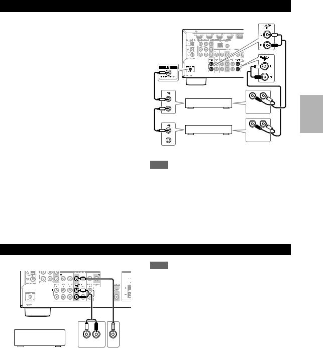
Connecting Onkyo u Components
1 |
Make sure that each Onkyo component is |
|
connected with an analog audio cable (connection |
|
F in the hookup examples) ( page 14). |
2 |
Make the uconnection (see the illustration). |
3 |
If you’re using an RI Dock or cassette tape deck, |
|
change the Input Display ( page 30). |
With u(Remote Interactive), you can use the following special functions:
System On/Auto Power On
When you start playback on a component connected via u, if the AV receiver is on Standby, it will automatically turn on and select that component as the input source.
Direct Change
When playback is started on a component connected via u, the AV receiver automatically selects that component as the input source.
Remote Control
You can use the AV receiver’s remote controller to control your other u-capable Onkyo components, pointing the remote controller at the AV receiver’s remote control sensor instead of the component. You must enter the appropriate remote control code first ( page 44).
|
R |
L |
e.g., CD player |
ANALOG |
|
AUDIO OUT |
||
|
|
|
|
R |
L |
e.g., DVD player |
ANALOG |
|
AUDIO OUT |
||
Note
•Use only ucables for uconnections. ucables are supplied with Onkyo players (DVD, CD, etc.).
•Some components have two ujacks. You can connect either one to the AV receiver. The other jack is for connecting additional u-capable components.
•Connect only Onkyo components to ujacks. Connecting other manufacturer’s components may cause a malfunction.
•Some components may not support all ufunctions. Refer to the manuals supplied with your other Onkyo components.
Connecting a Recording Component
See “Recording” on the recording ( page 31).
L |
R |
AUDIO |
VIDEO |
IN |
IN |
VCR, DVD recorder, cassette tape deck, CDR, MD recorder, etc.
Note
•The AV receiver must be turned on for recording. Recording is not possible while it’s in Standby mode.
•If you want to record directly from your TV or playback VCR to the recording VCR without going through the AV receiver, connect the TV/VCR’s audio and video outputs directly to the recording VCR’s audio and video inputs. See the manuals supplied with your TV and VCR for details.
•Video signals connected to composite video inputs can be recorded only via composite video outputs. If your TV/VCR is connected to a composite video input, the recording VCR must be connected to a composite video output.
•The surround sound and DSP listening modes cannot be recorded.
•Copy-protected Blu-ray discs and DVDs cannot be recorded.
•Sources connected to a digital input cannot be recorded. Only analog inputs can be recorded.
•DTS signals will be recorded as noise, so don’t attempt analog recording of DTS CDs or LDs.
En
15
Connecting Antenna
This section explains how to connect the supplied indoor FM antenna and AM loop antenna.
The AV receiver won’t pick up any radio signals without any antenna connected, so you must connect the antenna to use the tuner.
Caution
• Be careful that you don’t injure yourself when using thumbtacks.
|
|
|
Insert the plug fully |
Push. |
Insert wire. |
Release. |
into the jack. |
Assembling the AM loop antenna
Thumbtacks, etc.
AM loop antenna (supplied) |
Indoor FM antenna (supplied) |
Note
•Once your AV receiver is ready for use, you’ll need to tune into a radio station and position the antenna to achieve the best possible reception.
•Keep the AM loop antenna as far away as possible from your AV receiver, TV, speaker cables, and power cords.
Tip
•If you cannot achieve good reception with the supplied indoor FM antenna, try a commercially available outdoor FM antenna instead.
•If you cannot achieve good reception with the supplied indoor AM loop antenna, try using it with a commercially available outdoor AM antenna.
Connecting the Power Cord
1 Plug the power cord into an AC wall outlet. |
|
|
Note |
|
|
|
• Before connecting the power cord, connect all of your |
|
|
speakers and AV components. |
|
|
• Turning on the AV receiver may cause a momentary power |
|
|
surge that might interfere with other electrical equipment on the |
|
|
same circuit. If this is a problem, plug the AV receiver into a |
|
|
different branch circuit. |
|
En
16
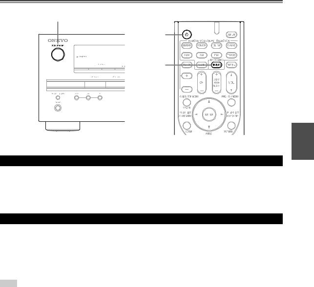
Turning On/Off the AV Receiver
8ON/STANDBY
8
RECEIVER
Turning On
1 Press 8ON/STANDBY on the front panel. or
Press RECEIVER followed by 8on the remote controller.
The AV receiver comes on, the display lights.
Turning Off
1 Press 8ON/STANDBY on the front panel. or
Press RECEIVER followed by 8on the remote controller.
The AV receiver will enter standby mode. To prevent any loud surprises when you turn on the AV receiver, always turn down the volume before you turn it off.
Tip
• See “Auto Standby” about a power management setting ( page 39).
En
17
Playback
The on-screen menus appear only on a TV that is connected to the HDMI OUT. If your TV is connected to the MONITOR OUT V or the COMPONENT VIDEO OUT, use the AV receiver’s display when changing settings.
This manual describes the procedure using the remote controller unless otherwise specified.
Playing the Connected Component
Operating with the remote controller
1 Press RECEIVER followed by INPUT SELECTOR.
2 Start playback on the source component.
See also:
• “Playing iPod/iPhone via USB” ( page 19)
• “Playing USB Device” ( page 20)
• “Listening to AM/FM Radio” ( page 20)
• “iPod/iPhone Playback via Onkyo Dock” ( page 42)
• “Controlling Other Onkyo Components” ( page 44)
3 |
To adjust the volume, use VOL q/w. |
4 |
Select a listening mode and enjoy! |
|
See also: |
•“Using the Listening Modes” ( page 26)
•“Audyssey” ( page 36)
Operating on the AV receiver
1 |
Use the input selector buttons to select the input |
|
source. |
2 |
Start playback on the source component. |
3 |
To adjust the volume, use the MASTER VOLUME |
|
control. |
4 |
Select a listening mode and enjoy! |
En
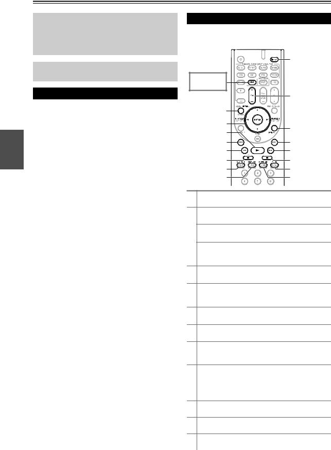
Controlling Contents of USB Devices
See “Controlling Other Onkyo Components” about the operation of other components ( page 44).
|
i |
|
Press USB |
|
|
first. |
|
|
|
j |
|
a |
|
|
b |
k |
|
c |
||
|
||
d |
l |
|
e |
m |
|
f |
n |
|
g |
o |
|
h |
p |
aTOP MENU
This button displays the top menu for each media or service.
bq/wand ENTER
These buttons navigate through the menus. e/r
This button cycles through pages.
PLAYLIST e/r
In Standard Mode (iPod/iPhone), this button selects playlists.
c1
This button starts playback.
d7
This button selects the beginning of the current song. Pressing this button twice selects the previous song.
e5
This button fast-reverses the current song.
f3
This button pauses playback.
gSEARCH
You can toggle between the playback screen and the list screen during playback.
hREPEAT
Press this button repeatedly to cycle through the repeat modes.
To cancel repeat playback, press REPEAT repeatedly until you select Off.
iDISPLAY
This button switches between song informations.
jCH +/–
In Standard Mode (iPod/iPhone), this button selects albums.
kRETURN
This button returns to the previous menu.
18
Loading...