


Operating Instructions
HT-S3800 5.1-Channel Home Theater System / 5.1-Channel Home Cinema System
HT-R395
HTP-395
AV Receiver
Speaker System

Contents
Thank you for buying this Onkyo product. Please read through these operating instructions so you will know how to operate your model properly.
Before you start . . . . . . . . . . . . . . . . . . . . . . . . . . . . 3
Checking what’s in the box . . . . . . . . . . . . . . . . . . . . . 3
Installing the receiver. . . . . . . . . . . . . . . . . . . . . . . . . . 3
Flow of settings on the receiver. . . . . . . . . . . . . 3
1 Controls and displays
Front panel . . . . . . . . . . . . . . . . . . . . . . . . . . . . . . . . . 4 Display . . . . . . . . . . . . . . . . . . . . . . . . . . . . . . . . . . . 5 Remote control . . . . . . . . . . . . . . . . . . . . . . . . . . . . . . 6 Loading the batteries. . . . . . . . . . . . . . . . . . . . . . . . . 7
Operating range of remote control . . . . . . . . . . . . . . . 7
2 Connecting your equipment
Placing the speakers . . . . . . . . . . . . . . . . . . . . . . . . . . 8 Affixing Non-Skid Pads . . . . . . . . . . . . . . . . . . . . . . . 8
Hints on the speaker placement. . . . . . . . . . . . . . . . . 8
Connecting the speakers . . . . . . . . . . . . . . . . . . . . . . . 9 Making cable connections . . . . . . . . . . . . . . . . . . . . . 10 HDMI cables . . . . . . . . . . . . . . . . . . . . . . . . . . . . . . 10 About HDMI . . . . . . . . . . . . . . . . . . . . . . . . . . . . . . 10 Analog audio cables . . . . . . . . . . . . . . . . . . . . . . . . 11 Digital audio cables . . . . . . . . . . . . . . . . . . . . . . . . . 11
Standard RCA video cables. . . . . . . . . . . . . . . . . . . 11 About video outputs connection . . . . . . . . . . . . . . . . . 11
Connecting a TV and playback components. . . . . . . . 12
Connecting using HDMI. . . . . . . . . . . . . . . . . . . . . . 12
Connecting your component with no HDMI
terminal. . . . . . . . . . . . . . . . . . . . . . . . . . . . . . . . . . 13 Connecting antennas. . . . . . . . . . . . . . . . . . . . . . . . . 14 Using external antennas . . . . . . . . . . . . . . . . . . . . . 14 Connecting a USB device . . . . . . . . . . . . . . . . . . . . . 15 Plugging in the receiver . . . . . . . . . . . . . . . . . . . . . . . 15
3 Basic playback
Playing a source . . . . . . . . . . . . . . . . . . . . . . . . . . . . 16
Selecting the audio input signal . . . . . . . . . . . . . . . . 16
Playing a USB device . . . . . . . . . . . . . . . . . . . . . . . . 18 Basic playback controls. . . . . . . . . . . . . . . . . . . . . . 18
Compressed audio compatibility . . . . . . . . . . . . . . . 18
Music playback using BLUETOOTH® wireless technology. . . . . . . . . . . . . . . . . . . . . . . . . . . . . . . . . 19
Pairing with the unit (Initial registration) . . . . . . . . . . 19
Listen to music on the unit from a BLUETOOTH capable device . . . . . . . . . . . . . . . . . . . . . . . . . . . . 19 Radio wave caution. . . . . . . . . . . . . . . . . . . . . . . . . 19 Listening to the radio . . . . . . . . . . . . . . . . . . . . . . . . . 20 Improving FM sound . . . . . . . . . . . . . . . . . . . . . . . . 20 Saving station presets . . . . . . . . . . . . . . . . . . . . . . . 20
Listening to station presets . . . . . . . . . . . . . . . . . . . 21
Naming preset stations . . . . . . . . . . . . . . . . . . . . . . 21
An introduction to RDS (For Europe) . . . . . . . . . . . . . 21 Searching for RDS programs. . . . . . . . . . . . . . . . . . 21 Displaying RDS information. . . . . . . . . . . . . . . . . . . 22
4 Listening to your system
Choosing the listening mode . . . . . . . . . . . . . . . . . . . 23 Listening in surround sound . . . . . . . . . . . . . . . . . . 23
Playing back in the STEREO mode . . . . . . . . . . . . 23
Using the DSP . . . . . . . . . . . . . . . . . . . . . . . . . . . . 23 Using Direct . . . . . . . . . . . . . . . . . . . . . . . . . . . . . . 23
Using the Music Optimizer . . . . . . . . . . . . . . . . . . . . 24
Setting the Audio options. . . . . . . . . . . . . . . . . . . . . . 24
Displaying the Fixed PCM Setting menu . . . . . . . . . . 26 Changing the TV format setting of Graphical User
Interface (Except for the U.S.A., Canada and Latin America models) . . . . . . . . . . . . . . . . . . . . . . . . . . . . 26
Changing the frequency step of AM Radio
(Except for the U.S.A., Canada and Latin America models) . . . . . . . . . . . . . . . . . . . . . . . . . . . . . . . . . . . 27
5 Setup
Using the Setup. . . . . . . . . . . . . . . . . . . . . . . . . . . . . 28 Manual speaker setup . . . . . . . . . . . . . . . . . . . . . . . . 28 Speaker Setting. . . . . . . . . . . . . . . . . . . . . . . . . . . . 28 X.Over. . . . . . . . . . . . . . . . . . . . . . . . . . . . . . . . . . . 29 Channel Level . . . . . . . . . . . . . . . . . . . . . . . . . . . . . 29 Speaker Distance . . . . . . . . . . . . . . . . . . . . . . . . . . 30 The Input Assign menu . . . . . . . . . . . . . . . . . . . . . . . 30 The Auto Power Down menu . . . . . . . . . . . . . . . . . . . 31 The HDMI Setup menu . . . . . . . . . . . . . . . . . . . . . . . 31
6 Additional information
Troubleshooting. . . . . . . . . . . . . . . . . . . . . . . . . . . . . 33 General. . . . . . . . . . . . . . . . . . . . . . . . . . . . . . . . . . 33 HDMI . . . . . . . . . . . . . . . . . . . . . . . . . . . . . . . . . . . 34
Important information regarding the HDMI
connection. . . . . . . . . . . . . . . . . . . . . . . . . . . . . . . . 34 USB messages . . . . . . . . . . . . . . . . . . . . . . . . . . . . 34 About the Speaker System . . . . . . . . . . . . . . . . . . . . 35 Precautions. . . . . . . . . . . . . . . . . . . . . . . . . . . . . . . 35
Effective Combination of Subwoofer and
Front/Center/Surround speakers . . . . . . . . . . . . . . . 35
Operation . . . . . . . . . . . . . . . . . . . . . . . . . . . . . . . . 35
Making amplifier settings . . . . . . . . . . . . . . . . . . . . . 35
Wall-mounting the Front/Center/Surround
speaker system. . . . . . . . . . . . . . . . . . . . . . . . . . . . 36 Resetting the main unit . . . . . . . . . . . . . . . . . . . . . . . 36 Cleaning the unit . . . . . . . . . . . . . . . . . . . . . . . . . . . . 36 Specifications . . . . . . . . . . . . . . . . . . . . . . . . . . . . . . 37 Software license notice . . . . . . . . . . . . . . . . . . . . . . . 39
2

Before you start |
Flow of settings on the receiver |
Checking what’s in the box
Please check that you’ve received the following supplied accessories:
•Remote control
•AAA size IEC R03 dry cell batteries (to confirm system operation) x2
•AM loop antenna
•FM wire antenna
•Speaker cables (3 m/10 ft.) x4
•Speaker cables (8 m/26 ft.) x2
•Non-Skid Pads x20
•Quick start guide
•Safety Brochure
Installing the receiver
•When installing this unit, make sure to put it on a level and stable surface.
Don’t install it on the following places:
–on a color TV (the screen may distort)
–near a cassette deck (or close to a device that gives off a magnetic field). This may interfere with the sound.
–in direct sunlight
–in damp or wet areas
–in extremely hot or cold areas
–in places where there is vibration or other movement
–in places that are very dusty
–in places that have hot fumes or oils (such as a kitchen)
The unit is a full-fledged AV receiver equipped with an abundance of functions and terminals. It can be used easily after following the procedure below to make the connections and settings.
The colors of the steps indicate the following:
Required setting item
Setting to be made as necessary
- - - - - - - - - - - - - - - - - - - - - - - - - - - - - - - - - - - - - - - - - -
1Connecting the speakers
Where you place the speakers will have a big effect on the sound.
•Placing the speakers (page 8)
•Connecting the speakers (page 9)
Ð
2Connecting the components
For surround sound, you’ll want to hook up using a digital connection from the Blu-ray Disc/DVD player to the receiver.
•About video outputs connection (page 11)
•Connecting a TV and playback components (page 12)
•Connecting antennas (page 14)
•Plugging in the receiver (page 15)
Ð
3PowerMake sureOn you’ve set the video input on your TV to this receiver. Check the manual that came with the TV if you don’t know how to do this.
Ð
3
4Making the initial settings according to the region and environment in which you live
•Changing the TV format setting of Graphical User Interface (Except for the U.S.A., Canada and Latin America models) (page 26)
•Changing the frequency step of AM Radio (Except for the U.S.A., Canada and Latin America models) (page 27)
Ð
5Specify the size and number of speakers you’ve connected
• Speaker Setting (page 28)
Ð
6The Input Assign menu (page 30)
(When using connections other than the recommended connections.)
The HDMI Setup menu (page 31)
(When the connected TV supports the HDMI Audio Return Channel function.)
Ð
7Basic playback (page 16)
•Selecting the audio input signal (page 16)
•Playing a USB device (page 18)
•Choosing the listening mode (page 23)
Ð
8Adjusting the sound as desired
•Using the Music Optimizer (page 24)
•Setting the Audio options (page 24)
•Manual speaker setup (page 28)

1: Controls and displays
Front panel
1 |
2 |
3 |
4 |
5 |
6 |
7 |
8 |
|
|
|
|
|
|
|
MASTER VOLUME |
 ON / STANDBY
USB
PHONES
TONE
5V/0.5A
AV RECEIVER HT-R395
9 |
10 |
11 |
12 |
1 ÍON/STANDBY
2BLUETOOTH
Switches to the BT Audio input
3 Remote sensor
Receives the signals from the remote control (see Operating range of remote control on page 7).
4Listening mode buttons
STEREO – Switches to the STEREO mode (page 23). SURROUND – Press for standard decoding and to switch between the modes of  Pro Logic II and NEO:6. DSP – Switches between the various surround modes (page 23).
5 Character display
See Display on page 5.
13
6HOME/ENTER/RETURN buttons
HOME – Use to access the Setup.
ENTER – Press to confirm the specified settings. RETURN – Use to return to the display immediately previous when making settings
7 Tuner control/Cursor buttons
TUNING – Used to find radio frequencies (page 20).
PRESET – Use to select preset radio stations (page 21).
These are also used to move the cursors when displaying the Setup, for example.
8
9 PHONES jack
Use to connect headphones. When the headphones are connected, there is no sound output from the speakers.
10TONE
Switches the display between Bass settings and Treble settings.
11TONE -/+
Press to change the settings while the Bass or Treble settings are displayed.
12INPUT SELECTOR buttons
Selects an input source (page 16).
13USB terminal
Use to connect your USB mass storage device as an audio source (page 15).
4
1 |
Controls and displays |
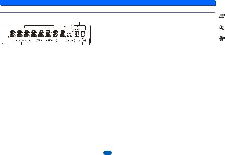
Display
14 15 16 14 17
18 |
19 |
20 |
21 |
21 |
22 |
14 Tuner indicators |
|
|
19 DTS indicators |
||
RDS – Lights when an RDS broadcast is received (page 21). (For Europe)
ST – Lights when a stereo FM broadcast is being received in auto stereo mode (page 20).
TUNE – Lights when a normal broadcast channel.
PRESET – Shows when a preset radio station is registered or called.
MEM – Blinks when a radio station is registered.
kHz/MHz – Lights when the character display is showing the currently received AM/FM broadcast frequency.
15 Speaker indicators
Shows if the speaker system is on or not.
SP |
A means the speaker system is on. |
SP |
means the speaker system is off. |
16 Sleep timer indicator
Lights when the receiver is in sleep mode (page 6).
17 PRESET information or input signal indicator
Shows the preset number of the tuner or the input signal type, etc.
18 Character display
Displays various system information.
DTS – Lights when a source with DTS encoded audio signals is detected.
HD – Lights when a source with DTS-EXPRESS or DTSHD encoded audio signals is detected.
96/24 – Lights when a source with DTS 96/24 encoded audio signals is detected.
NEO:6 – When one of the NEO:6 modes of the receiver is on, this lights to indicate NEO:6 processing (page 23).
20 Dolby Digital indicators
 D – Lights when a Dolby Digital encoded signal is detected.
 D+ – Lights when a source with Dolby Digital Plus encoded audio signals is detected.
 HD – Lights when a source with Dolby TrueHD encoded audio signals is detected.
 PLII – Lights to indicate
  Pro Logic II decoding (see
Listening in surround sound on page 23 for more on this).
21 SIGNAL SELECT indicators
DIGITAL – Lights when a digital audio signal is selected. Blinks when a digital audio signal is selected and selected audio input is not provided.
HDMI – Lights when an HDMI signal is selected. Blinks when an HDMI signal is selected and selected HDMI input is not provided.
22 DIR.
Lights when the DIRECT mode is switched on (page 23).
5

1 |
|
|
|
|
|
Controls and displays |
Remote control |
|
|
|
|
|
|
|
|
|
|
As for operating other devices, the remote control codes for |
8 TUNER control buttons |
|
|
|
|
|
the Onkyo products are preset. The settings cannot be |
See Listening to the radio on page 20. |
|
1 |
|
|
RECEIVER |
changed. |
9 AUDIO SEL |
|
|
|
|
1 |
ÍRECEIVER |
Press to select the audio input signal of the component to |
|
|
|
|
|
Switches the receiver between standby and on. |
play back (page 16). |
|
BD/DVD |
CBL/SAT |
STRM BOX |
|
2 |
Input function buttons |
10LATE NIGHT |
AUDIO SEL |
Use to select the input source to this receiver (page 16). This |
Turns ON and OFF the LATE NIGHT function (page 24). |
||||
|
|
|
9 |
will enable you to control other Onkyo components with the |
11M.OPT |
|
|
|
|
|
remote control. |
||
2 |
|
|
LATE NIGHT |
Press to restore CD quality sound to compressed audio |
||
|
|
10 |
3 |
USB control buttons |
||
|
|
sources (page 24). |
||||
|
|
|
|
Use to control the USB source. Operations other than USB |
12 |
|
|
|
|
11 |
are not possible. |
Mutes/unmutes the sound. |
|
TOP MENU |
|
|
4 |
Receiver control buttons |
13VOL +/– |
|
|
|
|
|
|
||
|
|
|
|
|
Q (QUICK MENU) – Use to access the Audio options |
Use to set the listening volume. |
3 |
|
|
|
|
(page 24). |
14SLEEP |
|
|
|
|
– Press to access the Setup (page 28). |
||
|
|
|
|
|
Press to change the amount of time before the receiver |
|
|
|
|
12 |
|
– Use to return to the display immediately previous |
switches into standby (30 min – 60 min – 90 min – Off). You |
QUICK MENU |
|
|
|
when making settings |
can check the remaining sleep time at any time by pressing |
|
|
|
|
|
5 |
/ // , ENTER |
SLEEP once. |
4 |
|
|
|
15DIMMER |
||
|
|
|
Use the arrow buttons when setting up your surround sound |
|||
|
|
|
13 |
system (page 28). |
Dims or brightens the display. The brightness can be |
|
|
|
|
6 Listening mode and component control buttons |
controlled in four steps. |
||
5 |
|
|
|
16 |
||
|
|
|
|
DIRECT – Press to select Direct playback (page 23). |
||
|
|
|
|
|
STEREO – Press to select stereo playback (page 23). |
Switches the display of this unit. The listening mode, sound |
|
|
|
|
|
volume or input name can be checked by selecting an input |
|
6 |
|
|
|
|
SURR – Press for standard decoding and to switch |
source. |
|
SURR |
DSP |
|
between the modes of Pro Logic II and NEO:6 |
|
|
|
|
TREBLE |
|
(page 23). |
|
|
7 |
|
|
DSP – Switches between the various surround modes |
|
||
|
|
|
|
|
||
|
|
|
|
(page 23). |
|
|
|
|
|
|
|
|
|
DISPLAY |
TUNING + |
EDIT |
SLEEP |
7 |
BASS +/–, TREBLE +/– |
|
Use to adjust Bass or Treble. |
|
|||||
PRESET - |
|
PRESET + |
14 |
• These controls are disabled when the listening mode is set |
|
|
|
15 |
|
||||
8 |
|
|
• |
to DIRECT. |
|
|
|
TUNING - |
BAND |
16 |
When the front speaker is set at SMALL in the Speaker |
|
|
|
TUNER |
|
|
Setting and the X.Over is set above 150 Hz, the subwoofer |
|
|
|
|
|
|
channel level will be adjusted by pressing BASS +/– |
|
|
|
|
|
|
|
|
|
(page 29).
6

1 |
Controls and displays |
Loading the batteries |
Operating range of remote control |
The batteries included with the unit are to check initial operations; they may not last over a long period. We recommend using alkaline batteries that have a longer life.
 WARNING
•Do not use or store batteries in direct sunlight or other excessively hot place, such as inside a car or near a heater. This can cause batteries to leak, overheat, explode or catch fire. It can also reduce the life or performance of batteries.
 CAUTION
•Incorrect use of batteries may result in such hazards as leakage and bursting. Observe the following precautions:
-Never use new and old batteries together.
-Insert the plus and minus sides of the batteries properly according to the marks in the battery case.
-Batteries with the same shape may have different voltages. Do not use different batteries together.
-When disposing of used batteries, please comply with governmental regulations or environmental public institution’s rules that apply in your country/area.
-When inserting the batteries, make sure not to damage the springs on the battery’s (–) terminals. This can cause batteries to leak or overheat.
The remote control may not work properly if:
•There are obstacles between the remote control and the receiver’s remote sensor.
•Direct sunlight or fluorescent light is shining onto the remote sensor.
•The receiver is located near a device that is emitting infrared rays.
•The receiver is operated simultaneously with another infrared remote control unit.
30°  30°
30° 
7 m (23 ft.)
7
2: Connecting your equipment
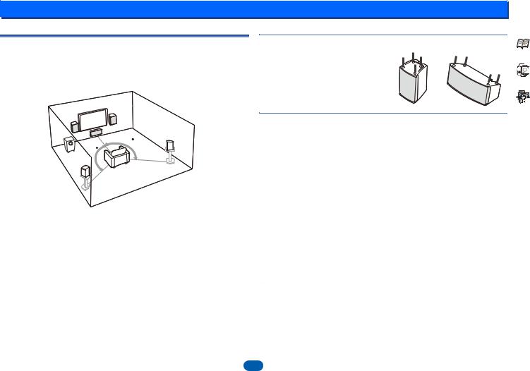
Placing the speakers
By connecting the left and right front speakers (L/R), the center speaker (C), the left and right surround speakers (SL/SR), and the subwoofer (SW), a 5.1 ch surround system can be enjoyed.
To achieve the best possible surround sound, install your speakers as shown below.
5.1 channel surround system:
Affixing Non-Skid Pads
Apply the accessory non-skid pads to the bottom surfaces of the front/center/surround speakers
R
L
SR
120
120
SW
SL
Subwoofer
•Orient the subwoofer’s front face pointing toward the listening position.
•When moving the subwoofer, avoid touching the bottom surface, since the speaker unit is located there.
•The subwoofer plays back the bass in monaural, making use of the fact that the human ear is not very sensitive to the direction of low-pitched sound. Because of this, the subwoofer can be installed almost anywhere. If it is installed too far away, however, the sound from the other speakers may become unnatural.
The degree of bass effect can be adjusted by moving the unit farther from or closer to the wall.
Front/Center/Surround speakers
•Labels located on the rear of each speaker indicate whether they are designed for front or surround use.
•Optional speaker stands can be purchased to facilitate optimal mounting of the surround speakers at or slightly above the listener’s ear height.
•The surround effect will be diminished if the surround speakers are mounted at extreme distances from the listener’s position.
Hints on the speaker placement
Where you put your speakers in the room has a big effect on the quality of the sound. The following guidelines should help you to get the best sound from your system.
•The subwoofer can be placed on the floor. Ideally, the other speakers should be at about ear-level when you’re listening to them. Putting the speakers on the floor (except the subwoofer), or mounting them very high on a wall is not recommended.
•For the best stereo effect, place the front speakers 2 m to 3 m (6 ft. to 9 ft.) apart, at equal distance from the TV.
•If you’re going to place speakers around your CRT TV, place the speakers at a sufficient distance from your CRT TV. Any other device liable to be influenced by magnetism (floppy disk drive, cassette tape recorder, video tape player, etc.) should also be kept at a distance from the subwoofer and other speakers.
•If you’re using a center speaker, place the front speakers at a wider angle. If not, place them at a narrower angle.
•It is best to angle the speakers towards the listening position. The angle depends on the size of the room. Use less of an angle for bigger rooms.
•The optimal positioning for surround speakers is just above ear height. Make sure the speakers don’t face each other. For DVD-Audio, the speakers should be more directly behind the listener than for home theater playback.
•Try not to place the surround speakers farther away from the listening position than the front and center speakers. Doing so can weaken the surround sound effect.
 CAUTION
•Make sure that all speakers are securely installed. This not only improves sound quality, but also reduces the risk of damage or injury resulting from speakers being knocked over or falling in the event of external shocks such as earthquakes.
•Install the center speaker below the TV so that the sound of the center channel is localized at the TV screen.
•Do not place the center speaker on top of the TV, the speaker may fall from the TV due to external shocks such as earthquakes, endangering those nearby or damaging the speaker.
8

|
|
|
|
|
|
|
|
|
|
|
|
|
|
|
|
|
|
|
|
|
|
|
|
|
|
|
2 |
|
|
|
|
|
|
|
|
|
Connecting your equipment |
||||||||||||||
|
|
Front right |
|
|
|
|
Front left Subwoofer |
||||||||||||||||||
|
|
||||||||||||||||||||||||
Connecting the speakers |
|||||||||||||||||||||||||
|
|
|
|
|
|
|
|
|
|
|
|
|
|
|
|
|
|
|
|
|
|
|
|||
The receiver will work with just two stereo speakers (the front speakers in the diagram) but |
|
|
|
|
|
|
|
|
Center |
||||||||||||||||
using at least three speakers is recommended, and a complete setup is best for surround |
|
|
|
|
|
|
|
|
|
|
|
|
|
|
|
|
|
|
|
|
|
|
|
||
|
|
|
|
|
|
|
|
|
|
|
|
|
|
|
|
|
|
|
|
|
|
|
|||
sound. |
|
|
|
|
|
|
|
|
|
|
|
|
|
|
|
|
|
|
|
|
|
|
|
||
|
|
|
|
|
|
|
|
|
|
|
|
|
|
|
|
|
|
|
|
|
|
|
|||
|
|
|
|
|
|
|
|
|
|
|
|
|
|
|
|
|
|
|
|
|
|
|
|||
Make sure you connect the speaker on the right to the right (R) terminal and the speaker on the left to the left (L) terminal. Also make sure the positive and negative (+/–) terminals on the receiver match those on the speakers.
You can use speakers with a nominal impedance between 6 Ω and 16 Ω.
Be sure to complete all connections before connecting this unit to the AC power source.
Bare wire connections
1 |
Twist exposed wire strands together. |
1 |
2 |
3 |
2 |
Push open the tabs and insert exposed wire. |
|
|
|
3 |
Release the tabs. |
|
12 mm |
|
|
|
|
|
|
|
|
|
(1/2 in.) |
|
Note |
|
|
|
|
|
|
|
|
|
|
|
|
|
|
|
|
|
|
|
|
|
|
|
|
|
|
|
|
|
|
|
|
|
|
|
• Connect the wire with the colored marker to the red (+) |
colored |
|
|
|
|
|
|
|
|
|
|
|
|
|
|
|
|
|
|
|
|
||
|
|
|
|
|
|
|
|
|
|
||
|
|
|
|
|
|
|
|
|
|
||
|
|
|
|
|
|
|
|
|
|||
|
|
|
|
|
|
|
|
|
|||
|
|
|
|
|
|
|
|
|
|
||
terminal; the plain wire to the black (–) terminal. |
marker |
|
|
|
|
|
|
|
|
|
|
|
|
|
|
|
|
|
|
|
|||
|
|
|
|
|
|
|
|
|
|
|
|
|
|
|
|
|
|
|
|
|
|
|
|
|
|
|
|
|
|
|
|
|
|
|
|
|
|
|
|
|
|
|
|
|
|
|
|
|
|
|
|
|
|
|
|
|
|
|
|
 CAUTION
•These speaker terminals carry HAZARDOUS LIVE voltage. To prevent the risk of electric shock when connecting or disconnecting the speaker cables, disconnect the power cord before touching any uninsulated parts.
•Make sure that all the bare speaker wire is twisted together and inserted fully into the speaker terminal. If any of the bare speaker wire touches the back panel it may cause the power to cut off as a safety measure.
•After connecting the plugs, pull lightly on the cables to make sure that the ends of the cables are securely connected to the terminals. Poor connections can create noise and interruptions in the sound.
•If the cables’ wires happen to be pushed out of the terminals, allowing the wires to come into contact with each other, it places an excessive additional load on the receiver. This may cause the amp to stop functioning, and may even damage the receiver.
•When using a set of speakers connected to an receiver, you won’t be able to obtain the normal stereo effect if the polarity (+, –) of one of the speakers (left or right) is reversed.
Check if the |
colors are the |
same. |
Surround right |
Surround left |
9

2
Making cable connections
Make sure not to bend the cables over the top of this unit (as shown in the illustration). If this happens, the magnetic field produced by the transformers in this unit may cause a humming noise from the speakers.
 Important
•Before making or changing connections, switch off the power and disconnect the power cord from the AC outlet.
•Before unplugging the power cord, switch the power into standby.
HDMI cables
Both video and sound signals can be transmitted simultaneously with one cable. If connecting the player and the TV via this receiver, for both connections, use HDMI cables.
HDMI
Be careful to connect the terminal in the proper direction.
 Note
Note
•Set the HDMI parameter in Setting the Audio options on page 24 to THRU (THROUGH) and set the input signal in
Selecting the audio input signal on page 16 to HDMI, if you want to hear HDMI audio output from your TV (no sound will be heard from this receiver).
|
|
|
|
|
|
|
Connecting your equipment |
||||
• |
If the video signal does not appear on your TV, try |
|
Note |
||||||||
|
adjusting the resolution settings on your component or |
• |
Use a High Speed HDMI®/™ Cable. If HDMI cable other |
||||||||
|
display. Note that some components (such as video game |
|
than a High Speed HDMI®/™ Cable is used, it may not |
||||||||
|
units) have resolutions that may not be displayed. In this |
|
work properly. |
||||||||
|
case, use a (analog) composite connection. |
|
|||||||||
|
• |
When an HDMI cable with a built-in equalizer is |
|||||||||
• |
When the video signal from the HDMI is 480i, 480p, 576i |
||||||||||
|
connected, it may not operate properly. |
||||||||||
|
or 576p, Multi Ch PCM sound and HD sound cannot be |
|
|||||||||
|
• |
3D, Deep Color, x.v.Color, 4K signal transfer and Audio |
|||||||||
|
received. |
||||||||||
|
|
Return Channel are only possible when connected to a |
|||||||||
|
|
|
|||||||||
|
|
|
compatible component. |
||||||||
About HDMI |
|
||||||||||
• |
HDMI format digital audio transmissions require a longer |
||||||||||
The HDMI connection transfers uncompressed digital video, |
|||||||||||
|
time to be recognized. Due to this, interruption in the audio |
||||||||||
as well as almost every kind of digital audio that the |
|
||||||||||
|
may occur when switching between audio formats or |
||||||||||
connected component is compatible with, including DVD- |
|
||||||||||
|
beginning playback. |
||||||||||
Video, DVD-Audio, SACD, Dolby Digital Plus, Dolby |
|
||||||||||
• |
Turning on/off the device connected to this unit’s HDMI |
||||||||||
TrueHD, DTS-HD Master Audio (see below for limitations), |
|||||||||||
|
OUT terminal during playback, or disconnecting/ |
||||||||||
Video CD/Super VCD and CD. |
|
||||||||||
|
connecting the HDMI cable during playback, may cause |
||||||||||
This receiver incorporates High-Definition Multimedia |
|
||||||||||
|
noise or interrupted audio. |
||||||||||
Interface (HDMI®) technology. |
|
||||||||||
|
|
|
|
|
|
|
|
|
|||
This receiver supports the functions described below through |
|
® |
|||||||||
HDMI connections. |
|
||||||||||
• |
Digital transfer of uncompressed video (contents |
|
|||||||||
|
protected by HDCP (1080p/24, 1080p/60, etc.)) |
|
|
|
|
|
|
|
|
|
|
• |
3D signal transfer |
|
|
|
|
|
|
|
|
|
|
|
|
|
|
|
|
|
|
|
|||
• |
Deep Color signal transfer |
|
|
|
|
|
|
|
|
|
|
• |
x.v.Color signal transfer |
The terms HDMI and HDMI High-Definition Multimedia |
|||||||||
• |
Audio Return Channel (see The HDMI Setup menu on |
||||||||||
Interface, and the HDMI Logo are trademarks or registered |
|||||||||||
|
page 31) |
||||||||||
|
trademarks of HDMI Licensing, LLC in the United States and |
||||||||||
• |
Input of multi-channel linear PCM digital audio signals |
||||||||||
other countries. |
|||||||||||
|
(192 kHz or less) for up to 8 channels |
|
|
|
|
|
|
|
|
|
|
•Input of the following digital audio formats:
–Dolby Digital, Dolby Digital Plus, DTS, High bitrate audio (Dolby TrueHD, DTS-HD Master Audio), DVD-Audio, CD, SACD (DSD 2 ch only), Video CD, Super VCD
•4K signal transfer
–This may not operate properly, depending on the connected equipment.
–4K 24p, 4K 25p, 4K 30p, 4K 50p and 4K 60p signals are supported.
•HDCP 2.2 compatible terminal
“x.v.Color” and |
are trademarks of Sony |
Corporation.
10
2
Analog audio cables
Use stereo RCA phono cables to connect analog audio components. These cables are typically red and white, and you should connect the red plugs to R (right) terminals and white plugs to L (left) terminals.
White (Left)
L |
|
|
AUD |
R |
IO |
|
Red (Right)
Digital audio cables
Commercially available coaxial digital audio cables or optical cables should be used to connect digital components to this receiver.
Coaxial digital |
COAXIAL |
|
IN |
OPTICAL |
|
audio cable |
|
|
|
IN |
|
|
|

 Optical cable
 Note
Note
•When connecting optical cables, be careful when inserting the plug not to damage the shutter protecting the optical socket.
•When storing optical cable, coil loosely. The cable may be damaged if bent around sharp corners.
•You can also use a standard RCA video cable for coaxial
digital connections.
Standard RCA video cables
These cables are the most common type of video connection and are used to connect to the composite video terminals. The yellow plugs distinguish them from cables for audio.
VIDEO
Yellow
Connecting your equipment 

About video outputs connection
This receiver is not loaded with a video converter. When you use HDMI cables for connecting to the input device, the same cables should be used for connecting to the TV.
The signals input from the analog (composite) video inputs of this unit will not be output from the HDMI OUT.
 Playback component
IN |
IN |
Terminal for connection |
|
|
|||
|
|
with source device |
|
HDMI |
VIDEO |
|
|
OUT |
MONITOR |
|
|
OUT |
Terminalforconnection |
||
|
|||
|
|
||
|
|
with TV monitor |
|
HDMI |
VIDEO |
The OSD will |
|
|
|
||
|
|
not appear. |
TV
Video signals can be output.
11
2 |
|
|
|
Connecting your equipment |
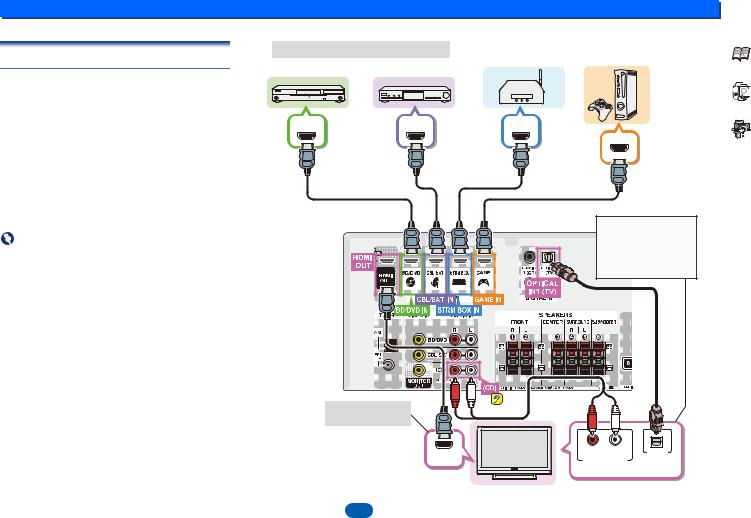
Connecting a TV and playback components |
HDMI/DVI-compatible components |
Streaming media player |
Game console |
|
|
Blu-ray Disc/DVD |
|
||
Connecting using HDMI |
player |
Set-top box |
|
|
|
|
|
|
|
If you have an HDMI or DVI (with HDCP) equipped |
|
|
|
|
component (Blu-ray Disc player, etc.), you can connect it to |
|
|
|
|
this receiver using a commercially available HDMI cable. |
|
|
|
|
• The following connection/setting is required to listen to the |
HDMI OUT |
HDMI OUT |
HDMI OUT |
|
sound of the TV over this receiver. |
|
|||
-If the TV does not support the HDMI Audio Return |
|
|
|
HDMI OUT |
Channel function, connect the receiver and TV with |
|
|
|
|
audio cables (as shown). |
|
|
|
|
-If the TV supports the HDMI Audio Return Channel |
|
|
|
|
function, the sound of the TV is input to the receiver via |
|
|
|
|
the HDMI terminal, so there is no need to connect an |
|
|
|
|
audio cable. In this case, set ARC at HDMI Setup to ON |
|
|
|
|
(see The HDMI Setup menu on page 31). |
|
|
|
|
-Please refer to the TV’s operation manual for directions |
|
|
|
If the TV does not support |
on connections and setup for the TV. |
|
|
|
|
Important |
|
|
|
the HDMI Audio Return |
|
|
|
Channel function, this |
|
• When the ARC function is ON and the receiver is |
|
|
|
connection is required to |
connected to a compatible TV with an HDMI cable, and |
|
|
|
listen to the TV sound over |
|
|
|
the receiver. |
|
you switch the input of the TV to composite, the input of the |
|
|
|
|
|
|
|
|
|
receiver may automatically switch to TV. If this happens, |
|
|
|
|
switch the receiver’s input back to the original input, or turn |
|
|
|
|
OFF the ARC function (see The HDMI Setup menu on |
|
|
|
|
page 31). |
|
|
|
|
 Note
Note
• In order to listen to the audio from the TV that is connected to this receiver using an analog audio cables, set-up for analog audio input is required (see The Input Assign menu on page 30).
OSD can only be output from HDMI.
HDMI IN |
R |
L |
OPTICAL |
|
ANALOG AUDIO OUT |
DIGITAL AUDIO OUT |
|||
|
||||
Select one
HDMI/DVI-compatible TV
12

2 |
|
|
|
|
|
|
|
Connecting your equipment |
Connecting your component with no HDMI |
|
|
|
|
Blu-ray Disc/DVD |
|
|
|
terminal |
|
|
|
|
player |
|
|
Set-top box |
This diagram shows connections of a TV and Blu-ray Disc/ |
|
|
|
|
|
|
|
|
DVD player (or other playback component) with no HDMI |
VIDEO OUT |
|
Select one |
VIDEO OUT |
|
Select one |
||
terminal to the receiver. |
|
|
||||||
|
ANALOG AUDIO OUT |
DIGITAL AUDIO OUT |
ANALOG AUDIO OUT |
DIGITAL AUDIO OUT |
||||
Important |
|
|||||||
|
R |
L |
OPTICAL |
COAXIAL |
R |
L |
OPTICAL COAXIAL |
|
•When the receiver and TV are connected by composite cable, the OSD function allowing display of the receiver’s settings, operations, etc., on the TV’s screen cannot be used. In this case, watch the receiver’s front panel display while performing the various operations and making settings.
 Note
Note
•You can only connect one component to the optical input terminal. If connecting other devices, please use a different method to connect the audio.
In order to listen to the audio from the source component that is connected to this receiver using an optical cable,
first, switch to the BD/DVD (Blu-ray Disc/DVD player) or CBL/SAT (set-top box), then press AUDIO SEL to choose the audio signal O1 (OPTICAL1) (see Selecting the audio input signal on page 16.
•You can only connect one component to the coaxial input terminal. If connecting other devices, please use a different method to connect the audio.
In order to listen to the audio from the source component that is connected to this receiver using a coaxial cable,
first, switch to the BD/DVD (Blu-ray Disc/DVD player) or CBL/SAT (set-top box), then press AUDIO SEL to choose the audio signal C1 (COAXIAL1) (see Selecting the audio input signal on page 16.
This connection is required in order to listen to the sound of the TV over the receiver.
OSD cannot be output.
R |
L |
OPTICAL |
ANALOG AUDIO OUT |
DIGITAL AUDIO OUT |
|
VIDEO IN |
Select one |
|
TV
13
 Loading...