


AV Receiver
HT-R320
Instruction Manual
Thank you for purchasing an Onkyo AV Receiver. Please read this manual thoroughly before making connections and plugging in the unit.
Following the instructions in this manual will enable you to obtain optimum performance and listening enjoyment from your new AV Receiver. Please retain this manual for future reference.
Contents |
|
Before using |
|
Important Safety Instructions ........................... |
2 |
Precautions ........................................................ |
3 |
Features ............................................................. |
4 |
Supplied accessories ......................................... |
4 |
Before Using the HT-R320 .............................. |
5 |
Facilities and connections |
|
Index to parts and controls ............................... |
6 |
Connecting to audio/video equipment ........... |
10 |
Positioning speakers/Connecting speakers .... |
12 |
Connecting antennas ....................................... |
14 |
Connections for remote control ( ) ............. |
16 |
Enjoying music or videos |
|
Enjoying music or videos with the |
|
HT-R320 ....................................................... |
17 |
Speaker setup .................................................. |
18 |
Changing the default settings according |
|
to your connections ...................................... |
21 |
Listening to the radio ...................................... |
22 |
Various functions common to all the sources .. |
24 |
Enjoying multi channel sources ..................... |
27 |
Enjoying the listening modes ......................... |
28 |
Audio adjust function ..................................... |
30 |
Recording a source ......................................... |
32 |
Remote controller |
|
Using the remote controller with your other |
|
AV components ............................................ |
33 |
Appendix |
|
Troubleshooting .............................................. |
35 |
Specifications ................................................. |
37 |
En
WARNING:
TO REDUCE THE RISK OF FIRE OR ELECTRIC SHOCK, DO NOT EXPOSE THIS APPARATUS TO RAIN OR MOISTURE.
CAUTION:
TO REDUCE THE RISK OF ELECTRIC SHOCK, DO NOT REMOVE COVER (OR BACK). NO USER-SERVICEABLE PARTS INSIDE. REFER SERVICING TO QUALIFIED SERVICE PERSONNEL.
WARNING |
|
AVIS |
RISK OF ELECTRIC SHOCK |
|
RISQUE DE CHOC ELECTRIQUE |
DO NOT OPEN |
|
NE PAS OUVRIR |
The lightning flash with arrowhead symbol, within an equilateral triangle, is intended to alert the user to the presence of uninsulated Òdangerous voltageÓ within the productÕs enclosure that may be of sufficient
magnitude to constitute a risk of electric shock to persons.
The exclamation point within an equilateral triangle is intended to alert the user to the presence of important operating and maintenance (servicing) instructions in the literature accompanying the appliance.
Important Safety Instructions
1.Read these instructions.
2.Keep these instructions.
3.Heed all warnings.
4.Follow all instructions.
5.Do not use this apparatus near water.
6.Clean only with dry cloth.
7.Do not block any ventilation openings. Install in accordance with the manufacturerÕs instructions.
8.Do not install near any heat sources such as radiators, heat registers, stoves, or other apparatus (including ampliÞers) that produce heat.
9.Do not defeat the safety purpose of the polarized or grounding-type plug. A polarized plug has two blades with one wider than the other. A grounding type plug has two blades and a third grounding prong. The wide blade or the third prong are provided for your safety. If the provided plug does not Þt into your outlet, consult an electrician for replacement of the obsolete outlet.
10.Protect the power cord from being walked on or pinched particularly at plugs, convenience receptacles, and the point where they exit from the apparatus.
11.Only use attachments/accessories speciÞed by the manufacturer.
12. Use only with the cart, stand, tripod, bracket, or table speciÞed by the manufacturer, or sold with the apparatus. When a cart is used, use caution when moving the cart/ apparatus combination to avoid injury from tip-over.
13.Unplug this apparatus during lightning storms or when unused for long periods of time.
14.Refer all servicing to qualiÞed service personnel. Servicing is required when the apparatus has been damaged in any way, such as power-supply cord or plug is damaged, liquid has been spilled or objects have fallen into the apparatus, the apparatus has been exposed to rain or moisture, does not operate normally, or has been dropped.
15.Damage Requiring Service
Unplug the apparatus from the wall outlet and refer servicing to qualiÞed service personnel under the following conditions:
A.When the power-supply cord or plug is damaged,
B.If liquid has been spilled, or objects have fallen into the apparatus,
C.If the apparatus has been exposed to rain or water,
D.If the apparatus does not operate normally by following the operating instructions. Adjust only those controls that are covered by the operating instructions as an improper adjustment of other controls may result in damage and will often require extensive work by a qualiÞed technician to restore the apparatus to its normal operation,
E.If the apparatus has been dropped or damaged in any way, and
F.When the apparatus exhibits a distinct change in performance this indicates a need for service.
16.Object and Liquid Entry
Never push objects of any kind into the apparatus through openings as they may touch dangerous voltage points or short-out parts that could result in a Þre or electric shock.
The apparatus shall not be exposed to dripping or splashing and no objects Þlled with liquids, such as vases shall be placed on the apparatus.
DonÕt put candles or other burning objects on top of this unit.
17.Batteries
Always consider the environmental issues and follow local regulations when disposing of batteries.
18.If you install the apparatus in a built-in installation, such as a bookcase or rack, ensure that there is adequate ventilation.
Leave 20 cm (8") of free space at the top and sides and 10 cm (4") at the rear. The rear edge of the shelf or board above the apparatus shall be set 10 cm (4") away from the rear panel or wall, creating a ßue-like gap for warm air to escape.
2

Precautions
For U.S. models
Note to CATV system installer:
This reminder is provided to call the CATV system installer’s attention to Section 820-40 of the NEC which provides guidelines for proper grounding and, in particular, specifies that the cable ground shall be connected to the grounding system of the building, as close to the point of cable entry as practical.
FCC information for user
CAUTION:
The user changes or modifications not expressly approved by the party responsible for compliance could void the user’s authority to operate the equipment.
NOTE:
This equipment has been tested and found to comply with the limits for a Class B digital device, pursuant to Part 15 of the FCC Rules.
These limits are designed to provide reasonable protection against harmful interference in a residential installation. This equipment generates, uses and can radiate radio frequency energy and, if not installed and used in accordance with the instructions, may cause harmful interference to radio communications. However, there is no guarantee that interference will not occur in a particular installation.
If this equipment does cause harmful interference to radio or television reception, which can be determined by turning the equipment off and on, the user is encouraged to try to correct the interference by one or more of the following measures:
•Reorient or relocate the receiving antenna.
•Increase the separation between the equipment and receiver.
•Connect the equipment into an outlet on a circuit different from that to which the receiver is connected.
•Consult the dealer or an experienced radio/TV technician for help.
For Canadian models
NOTE: THIS CLASS B DIGITAL APPARATUS COMPLIES WITH CANADIAN ICES-003.
For models having a power cord with a polarized plug:
CAUTION: TO PREVENT ELECTRIC SHOCK, MATCH WIDE BLADE OF PLUG TO WIDE SLOT, FULLY INSERT.
Modèle pour les Canadien
REMARQUE: CET APPAREIL NUMÉRIQUE DE LA CLASSE B EST CONFORME A LA NORME NMB-003 DU CANADA.
Sur les modèles dont la fiche est polarisée:
ATTENTION: POUR ÉVITER LES CHOCS ÉLECTRIQUES, INTRODUIRE LA LAME LA PLUS LARGE DE LA FICHE DANS LA BORNE CORRESPONDANTE DE LA PRISE ET POUSSER JUSQU’AU FOND.
1.Recording Copyright—Unless it’s for personal use only, recording copyrighted material is illegal without permission of the copyright holder.
2.AC Fuse—The AC fuse inside the HT-R320 is not userserviceable. If you cannot turn on the HT-R320, contact your Onkyo dealer.
3.Care—Occasionally you should dust the HT-R320 all over with a soft cloth. For stubborn stains, use a soft cloth dampened with a weak solution of mild detergent and water. Dry the HT-R320 immediately afterwards with a clean cloth. Don’t use abrasive cloths, thinners, alcohol, or other chemical solvents, because they may damage the finish or remove the panel lettering.
4.Power
WARNING
BEFORE PLUGGING IN THE UNIT FOR THE FIRST TIME, READ THE FOLLOWING SECTION CAREFULLY.
AC outlet voltages vary from country to country. Make sure that the voltage in your area meets the voltage requirements printed on the HT-R320’s rear panel (e.g., AC 230 V, 50 Hz or AC 120 V, 60 Hz).
Setting the [STANDBY/ON] switch to STANDBY does not fully shutdown the HT-R320. If you do not intend to use the HT-R320 for an extended period, remove the power cord from the AC outlet.
3
Features
Amplifier Features
•5 × 100 W/Channel @ 8Ω, 20–20 kHz, 0.08% THD
•WRAT-Wide Range Amplifier Technology
•Optimum Gain Volume Circuitry
•DTS, Dolby Digital, Dolby Pro Logic II
•CinemaFILTER
•Non-Scaling Configuration
•A-Form–Auto Format Sensing
•Linear PCM 96 kHz/24-bit D/A Converters
•Advanced 24-bit DSP Chips
•2 Digital Inputs (Optical/Coaxial)
•Subwoofer Pre Out
•Dot Matrix FL Display
•Crossover Adjustment (60/80/100/120/150 Hz)
•Color-Coded Speaker Posts
FM/AM Tuner Features
•30 FM/AM random presets
•FM auto tuning
•FM indoor antenna supplied
•AM indoor antenna supplied
*Manufactured under license from Dolby Laboratories. “Dolby”, “Pro Logic” and the double-D symbol are trademarks of Dolby Laboratories.
**“DTS” and “DTS Digital Surround” are registered trademarks of Digital Theater Systems, Inc.
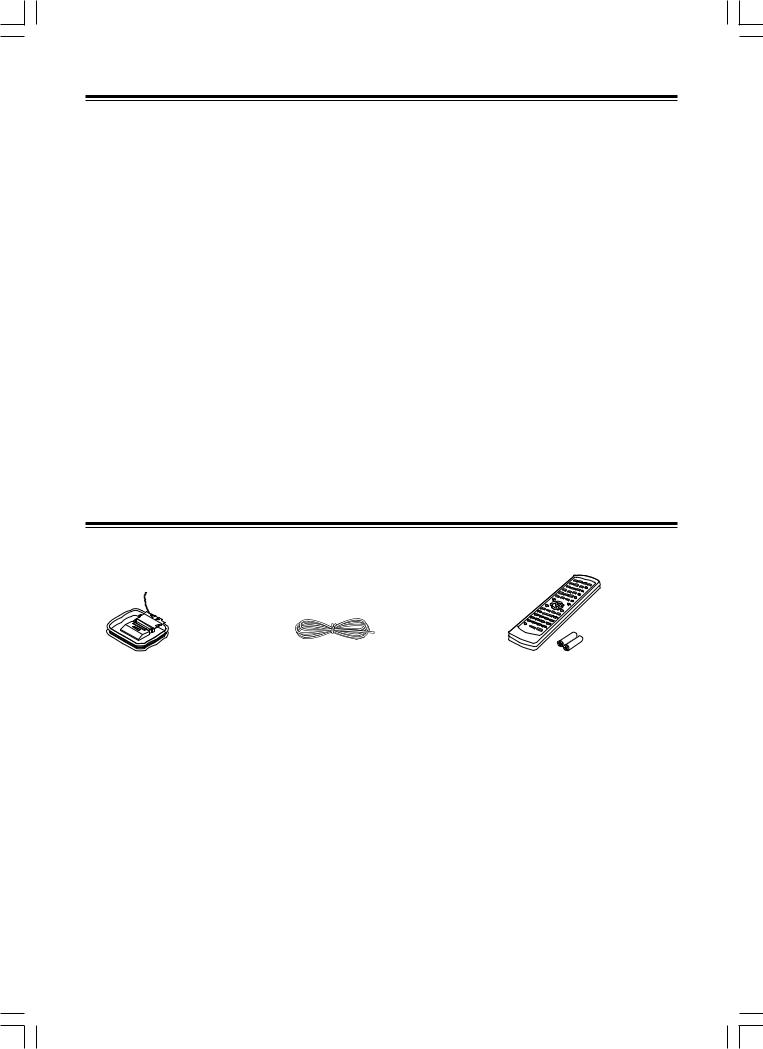
Supplied accessories
Check that the following accessories are supplied with the HT-R320.
AM loop antenna × 1 |
FM indoor antenna × 1 |
Remote controller × 1 |
|
|
RC-479S |
|
|
Batteries (AA/R6) × 2 |
The alphabet displayed at the end of the product name found in catalogs and on the packages represents the color of this receiver. Though the color varies, the specifications and operations are the same.
4
Before Using the HT-R320
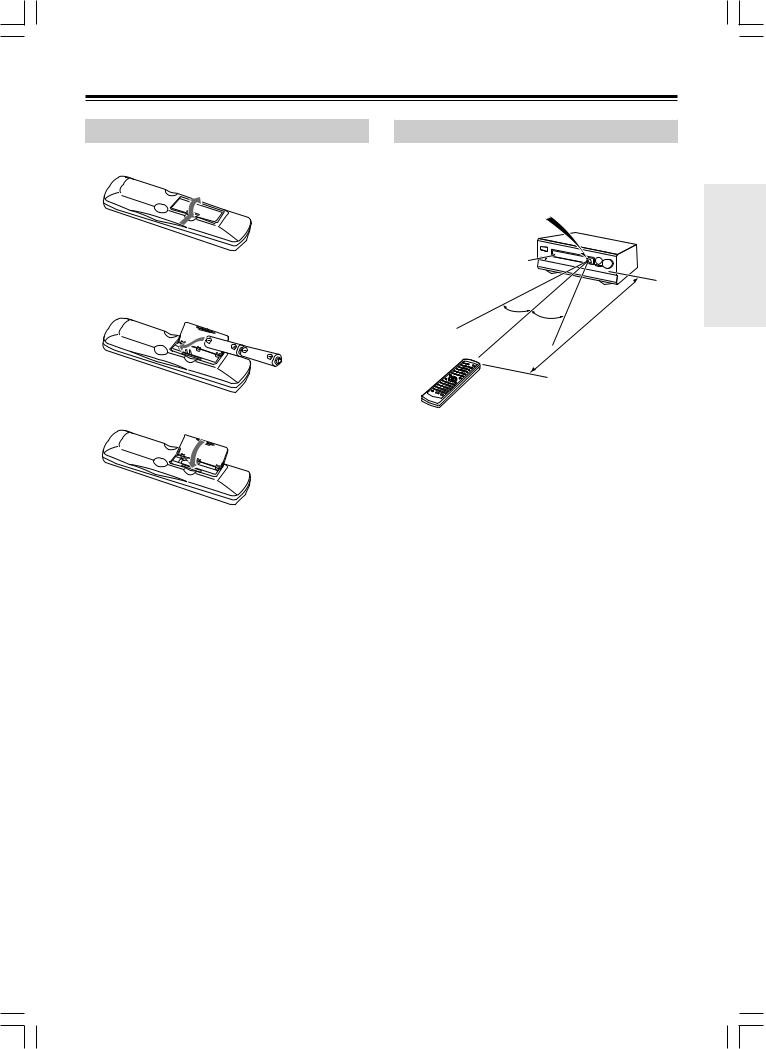
Installing the Batteries
1 Open the battery compartment, as shown.
2Insert the two supplied batteries (AA/R6) in accordance with the polarity diagram inside the battery compartment.
Using the Remote Controller
To use the remote controller, point it at the HT-R320’s remote control sensor, as shown below. The HT-R320’s STANDBY indicator flashes while a signal is being received from the remote controller.
Remote control sensor
HT-R320
Standby indicator
30˚ |
|
|
feet |
(5m) |
30˚ |
|
|
||
|
|
|
||
|
16 |
|
|
|
|
|
|
|
|
|
|
. |
|
|
|
|
Approx |
|
|
3 Close the battery compartment.
Notes
•The supplied batteries should last for about six months, although this will vary with usage.
•If the remote controller doesn’t work reliably, try replacing both batteries.
•Don’t mix new and old batteries, or different types of batteries.
•If you intend not to use the remote controller for a long time, remove the batteries to prevent possible leakage and corrosion.
•Flat batteries should be removed as soon as possible to prevent possible leakage and corrosion.
Notes
•The remote controller may not work reliably if the HT-R320 is subjected to bright light, such as direct sunlight or inverter-type fluorescent lights. Keep this in mind when installing the HTR320.
•If another remote controller of the same type is used in the same room, or the HT-R320 is installed close to equipment that uses infrared rays, the remote controller may not work reliably.
•Don’t put anything, such as a book, on the remote controller, because the buttons may be pressed inadvertently, thereby draining the batteries.
•The remote controller may not work reliably if the HT-R320 is installed in a rack behind colored glass doors. Keep this in mind when installing the HT-R320.
•The remote controller will not work if there’s an obstacle between it and the HT-R320’s remote control sensor.
5
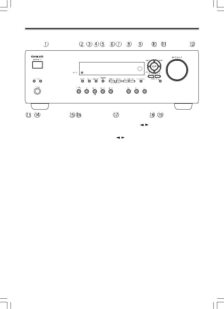
Index to parts and controls
Front panel
|
|
|
|
|
|
|
|
|
|
|
|
|
|
|
|
|
|
|
|
|
|
|
|
|
|
|
|
|
|
|
|
|
|
|
|
|
|
|
|
|
|
|
|
|
|
|
|
|
|
|
|
|
|
|
|
|
|
|
|
|
|
|
|
|
|
|
|
|
|
|
|
|
|
|
|
|
|
|
|
|
|
|
|
|
|
|
|
|
|
|
|
|
|
|
|
|
|
|
|
|
|
|
|
|
|
|
|
|
|
|
|
|
|
|
|
|
|
|
|
|
|
|
|
|
|
|
|
|
|
|
|
|
|
|
|
|
|
|
|
|
|
|
|
|
|
|
|
|
|
|
|
|
|
|
|
|
|
|
|
|
|
|
|
|
|
|
|
|
|
|
|
|
|
|
|
|
|
|
|
|
|
|
|
|
|
|
|
|
|
|
|
|
|
|
|
|
|
|
|
|
|
|
|
|
|
|
|
|
|
|
|
|
|
|
|
|
|
|
|
|
|
|
|
|
|
|
|
|
|
|
|
|
|
|
|
|
|
|
|
|
|
|
|
|
|
|
|
|
|
|
|
|
|
|
|
|
|
|
|
|
|
|
|
|
|
|
|
|
|
|
|
|
|
|
|
|
|
|
|
|
|
|
|
|
|
|
|
|
|
|
|
|
|
|
|
|
|
|
|
|
|
|
|
|
|
|
|
|
|
|
|
|
|
|
|
|
|
|
|
|
|
|
|
|
|
|
|
|
|
|
|
|
|
|
|
|
|
|
|
|
|
|
|
|
|
|
|
|
|
|
|
|
|
|
|
|
|
|
|
|
|
|
|
|
|
|
|
|
|
|
|
|
|
|
|
|
|
|
|
|
|
|
|
|
|
|
|
|
|
|
|
|
|
|
|
|
|
|
|
|
|
|
|
|
|
|
|
|
|
|
|
|
|
|
|
|
|
|
|
|
|
|
|
|
|
|
|
|
|
|
|
|
|
|
|
|
|
|
|
|
|
|
|
|
|
|
|
|
|
|
|
|
|
|
|
|
|
|
|
|
|
|
|
|
|
|
|
|
|
|
|
|
|
|
|
|
|
|
|
|
|
|
|
|
|
|
|
|
|
|
|
|
|
|
|
|
|
|
|
|
|
|
|
|
|
|
|
|
|
|
|
|
|
|
|
|
|
|
|
|
|
|
|
|
|
|
|
|
|
|
|
|
|
|
|
|
|
|
|
|
|
|
|
|
|
|
|
|
|
|
|
|
|
|
|
|
|
|
|
|
|
|
|
|
|
|
|
|
|
|
|
|
|
|
|
|
|
|
|
|
|
|
|
|
|
|
|
|
|
|
|
|
|
|
|
|
|
|
|
|
|
|
|
|
|
|
|
|
|
|
|
|
|
|
|
|
|
|
|
|
|
|
|
|
|
|
|
|
|
|
|
|
|
|
|
|
|
|
|
|
|
|
|
|
|
|
|
|
|
|
|
|
|
|
|
|
|
|
|
|
|
|
|
|
|
|
|
|
|
|
|
|
|
|
|
|
|
|
|
|
|
|
|
|
|
|
|
|
|
|
|
|
|
|
|
|
|
|
|
|
|
|
|
|
|
|
|
|
|
|
|
|
|
|
|
|
|
|
|
|
|
|
|
|
|
|
|
|
|
|
|
|
|
|
|
|
|
|
|
|
|
|
|
|
|
|
|
|
|
|
|
|
|
|
|
|
|
|
|
|
|
|
|
|
|
|
|
|
|
|
|
|
|
|
|
|
|
|
|
|
|
|
|
|
|
|
|
|
|
|
|
|
|
|
|
|
|
|
|
|
|
|
|
|
|
|
|
|
|
|
|
|
|
|
|
|
|
|
|
|
|
|
|
|
|
|
|
|
|
|
|
|
|
|
|
|
|
|
|
|
|
|
|
|
|
|
|
|
|
|
|
|
|
|
|
|
|
|
|
|
|
|
|
|
|
|
|
|
|
|
|
|
|
|
|
|
|
|
|
|
|
|
|
|
|
|
|
|
|
|
|
|
|
|
|
|
|
|
|
|
|
|
|
|
|
|
|
|
|
|
|
|
|
|
|
|
|
|
|
|
|
|
|
|
|
|
|
|
|
|
|
|
|
|
|
|
|
|
|
|
|
|
|
|
|
|
|
|
|
|
|
|
|
|
|
|
|
|
|
|
|
|
|
|
|
|
|
|
|
|
|
|
|
|
|
|
|
|
|
|
|
|
|
|
|
|
|
|
|
|
|
|
|
|
|
|
|
|
|
|
|
|
|
|
|
|
|
|
|
|
|
|
|
|
|
|
|
|
|
|
|
|
|
|
|
|
|
|
|
|
|
|
|
|
|
|
|
|
|
|
|
|
|
|
|
|
|
|
|
|
|
|
|
|
|
|
|
|
|
|
|
|
|
|
|
|
|
|
|
|
|
|
|
|
|
|
|
|
|
|
|
|
|
|
|
|
|
|
|
|
|
|
|
|
|
|
|
|
|
|
|
|
|
|
|
|
|
|
|
|
|
|
|
|
|
|
|
|
|
|
|
|
|
|
|
|
|
|
|
|
|
|
|
|
|
|
|
|
|
|
|
|
|
|
|
|
|
|
|
|
|
|
|
|
For operational instructions, refer to the page indicated in brackets. |
|
|
8 TUNING / buttons [22] |
|||||||||||||||||||||||||||||||||||||||||||||||||||
1 STANDBY/ON button [17] |
|
|
Use these buttons to change the tuner frequency. |
|||||||||||||||||||||||||||||||||||||||||||||||||||
|
|
When FM is selected, you can hold down one of the TUNING |
||||||||||||||||||||||||||||||||||||||||||||||||||||
When STANDBY/ON button is pressed to ON, the display will |
|
|
||||||||||||||||||||||||||||||||||||||||||||||||||||
/ |
|
buttons and then release it to activate the auto-search |
||||||||||||||||||||||||||||||||||||||||||||||||||||
light to show the current volume setting for about 5 seconds then |
|
|
feature. It will search for a station in the direction of the button you |
|||||||||||||||||||||||||||||||||||||||||||||||||||
show the current sound input source. Pressing the button again |
|
|
pressed and stop when it tunes into one. |
|||||||||||||||||||||||||||||||||||||||||||||||||||
returns the HT-R320 to the standby state. This state turns off the |
|
|
9 Remote control sensor [5] |
|||||||||||||||||||||||||||||||||||||||||||||||||||
display, disables control functions. |
|
|
||||||||||||||||||||||||||||||||||||||||||||||||||||
2 STANDBY indicator [17] |
|
|
This sensor receives the control signals from the remote controller. |
|||||||||||||||||||||||||||||||||||||||||||||||||||
|
|
|
|
|
|
|
|
|
|
|
|
|
|
|
|
|
|
|
|
|
|
|
|
|
|
|
|
|
|
|
||||||||||||||||||||||||
Lights when the HT-R320 is in the standby state and flashes when a |
|
|
0 LISTENING MODE buttons [27, 29] |
|||||||||||||||||||||||||||||||||||||||||||||||||||
signal is received from the remote controller. |
|
|
Press these buttons to select a listening mode for the current source. |
|||||||||||||||||||||||||||||||||||||||||||||||||||
3 DIMMER button [25] |
|
|
||||||||||||||||||||||||||||||||||||||||||||||||||||
|
|
Press the DSP button to recall the Onkyo-original DSP modes in |
||||||||||||||||||||||||||||||||||||||||||||||||||||
|
|
|
|
|
|
|
|
|
|
|
|
|
|
|
|
|
|
|
|
|
|
|
|
|
|
sequence. Press the DIRECT, STEREO or SURROUND button to |
||||||||||||||||||||||||||||
Press to set the brightness of the front display. The brightness
changes to normal, dim and very dim.
recall the corresponding listening mode directly.
4DIGITAL INPUT button [21]
When digital components are connected to the DIGITAL INPUT jacks of the HT-R320, use this button to assign the DIGITAL INPUT jacks to them according to their forms of connection.
5SUBWOOFER MODE button [20]
Press to select the subwoofer mode.
6MEMORY button [23]
This button is used to assign the radio station that is currently tuned in to a preset channel or delete a previously preset station.
7FM MODE button [22, 23]
Press to switch the reception mode between stereo and monaural. If audio is interrupted or noise interferes with audio during FM stereo broadcasting, press this button to switch to the monaural reception mode.
-PRESET/ADJUST  /
/ buttons [18, 19, 23, 30]
These buttons make it possible to store desired radio stations under the desired preset numbers and recall them with an easy operation. Also, these buttons adjust the values and parameters of the mode selected using the AUDIO ADJUST, SPEAKER ADJUST or AUDIO SELECTOR button.
=MASTER VOLUME dial [17]
The MASTER VOLUME dial is used to control the volume level. Turn the dial clockwise to increase the volume level and counterclockwise to decrease it.
~SPEAKERS A/B buttons [17, 24]
Press SPEAKERS A/B to turn on/off the speaker system A/B. The (SPEAKERS) A/B indicators corresponding to the selected speaker system light up. You can use SPEAKERS A and B simultaneously.
!PHONES jack [24]
This is a standard stereo jack for connecting stereo headphones. The audio for the front right and left speakers are sent to the headphone speakers.
6
Index to parts and controls
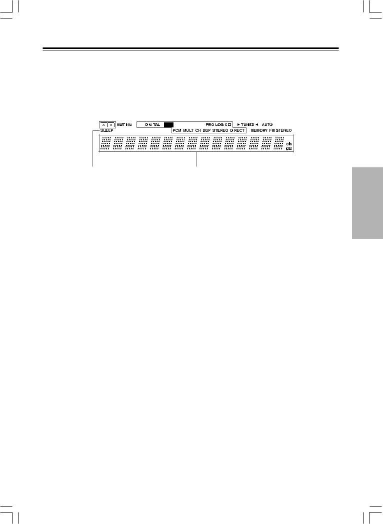
Display
|
|
|
|
|
|
|
|
|
|
|
|
|
e g |
|||
a b |
|
|
|
c |
|
|
|
d |
f |
|
||||||
|
|
|
|
|
|
|
|
|
|
|
|
|
|
|
|
|
|
|
|
|
|
|
|
|
|
|
|
|
|
|
|
|
|
|
|
|
|
|
|
|
|
|
|
|
|
|
|
|
|
|
|
|
|
|
|
|
|
|
|
|
|
|
|
|
|
|
|
|
|
|
|
|
|
|
|
|
|
|
|
|
|
|
|
|
|
|
|
|
|
|
|
|
|
|
|
|
|
|
|
|
|
h
@DISPLAY button [25]
Each time you press the DISPLAY button, the display changes.
#AUDIO SELECTOR button [26, 27]
Press to select an audio input signal format other than FM and AM. Each time this button is pressed, the setting cycles.
$Input selector buttons (DVD, VIDEO 1, VIDEO 2, VIDEO 3, TAPE, TUNER, and CD) [17, 21-23, 26, 27, 32]
These buttons are used to select the input source. Pressing and holding the TAPE button for about 2 seconds allows the TAPE and MD sources to be switched.
%SPEAKER ADJUST button [18, 19]
Press to select speaker setting item.
^AUDIO ADJUST button [30]
Press to adjust bass, treble, late night function, cinema filter, Panorama, Dimension and Center Width function setting.
i
a(SPEAKERS) A/B indicators [17, 24]
Shows the current speaker system in use.
bMUTING indicator [24]
Flashes when the mute function is active.
cSource/Listening mode indicators [17, 29]
One of these indicators lights to show the format of the current source as “PCM”, “ŸDIGITAL” or “DTS”. In addition, one of the listening mode indicators “Ÿ PRO LOGIC II”, “MULTI CH”, “DSP”, “STEREO” and “DIRECT” lights according to the current listening mode.
dTUNED indicator [22]
Lights up when a radio station is received.
eMEMORY indicator [23]
Lights up when the MEMORY button is pressed in the radio station preset operation.
fAUTO indicator [22]
Lights up to indicate auto reception mode (stereo/monaural). At this time, interstation noise will be muted (FM only). It extinguishes when the monaural reception mode is started by pressing the FM MODE button.
gFM STEREO indicator [22]
Lights up when an FM stereo broadcast station is received.
hSLEEP indicator [25]
Lights up when the sleep timer is active.
iMulti function display
In usual operation, shows the current input source and volume. When the FM or AM input is selected, it shows the frequency and preset number. When the DISPLAY button is pressed, it shows the current input source and the listening mode.
7
Index to parts and controls
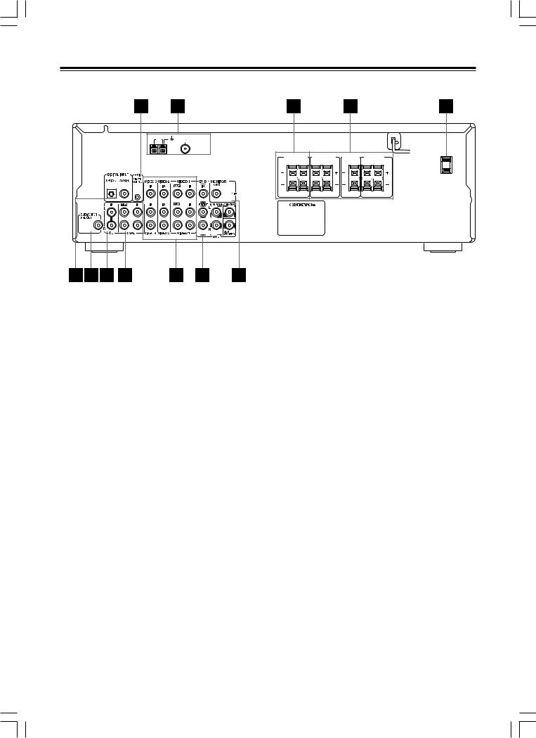
Rear panel
AM |
FM |
75 ANTENNA |
For operational instructions, refer to the page indicated in brackets.
1  REMOTE CONTROL [16]
Connect the Onkyo components that have  connectors such as a CD player, and cassette tape deck using the
  cables provided with them. When these components are interconnected, they can be controlled from the remote controller provided with the HT-R320.
For correct operation, the audio connection cables must also be connected. This applies to both remote and standard operation.
2ANTENNA [14, 15]
These terminals are for connecting the FM antenna and AM antenna.
3FRONT SPEAKERS B [13]
These terminals are for connecting the speaker system B.
4FRONT SPEAKERS A, CENTER SPEAKER and SURROUND SPEAKERS [13]
These terminals are for connecting the speaker system A, including the center and surround speakers.
5AC OUTLET [11]
The HT-R320 is supplied with AC outlet for connecting the power cord from other devices so that their power is supplied through the HT-R320. By doing this, you can use the STANDBY/ON button on the HT-R320 to turn on and off the connected devices as well.
6DIGITAL INPUT OPTICAL, COAXIAL [10, 11]
These are digital audio inputs. There is 1 optical jack and 1 coaxial jack. The inputs accept digital audio signals from DVD, LD, CD, or other digital source.
7SUBWOOFER PRE OUT [13]
This terminal is for connecting an active subwoofer.
FRONT |
|
FRONT |
|
CENTER |
SURROUND |
|
|
SPEAKERS B |
SPEAKERS A |
SPEAKER |
SPEAKERS |
AC OUTLET |
|||
R |
L |
R |
L |
|
R |
L |
|
8CD IN [10]
Connect the output terminal on the CD player to the CD IN L/R jacks on the HT-R320.
9TAPE IN/OUT [10]
Connect the output terminals (PLAY) of the cassette tape deck or MD recorder to the TAPE IN L/R jacks on the HT-R320 and the input terminals (REC) to the TAPE OUT L/R jacks.
pVIDEO 1 IN/OUT, VIDEO 2 IN, VIDEO 3 IN [11]
Connect the output terminals (PLAY) of the video cassette recorder to the VIDEO 1 IN L/R jacks on the HT-R320 and the input terminals (REC) to the VIDEO 1 OUT jacks.
Connect the output terminals of the video cassette player or satellite tuner to the VIDEO 2 IN or VIDEO 3 IN jacks on the HT-R320.
qDVD [11]
Connect the DVD player. If the DVD player has 5.1 channel output terminals, connect each terminal to the FRONT L/R, CENTER, SUBWOOFER, and SURR L/R terminals on the HT-R320. If the DVD player has only 2 channel output terminals, connect to the FRONT L/R terminals on the HT-R320.
wMONITOR OUT [10]
This output is for connecting television monitors or projectors.
Tip
The audio input jacks of the HT-R320 do not accept direct connection of an analog turnable.
If you want to connect a turntable to the HT-R320 prepare a phono equalizer and connect it to the unused audio input jacks (IN L/R).
Refer to the instruction manuals of the phono equalizer and turntable for details.
8
Index to parts and controls
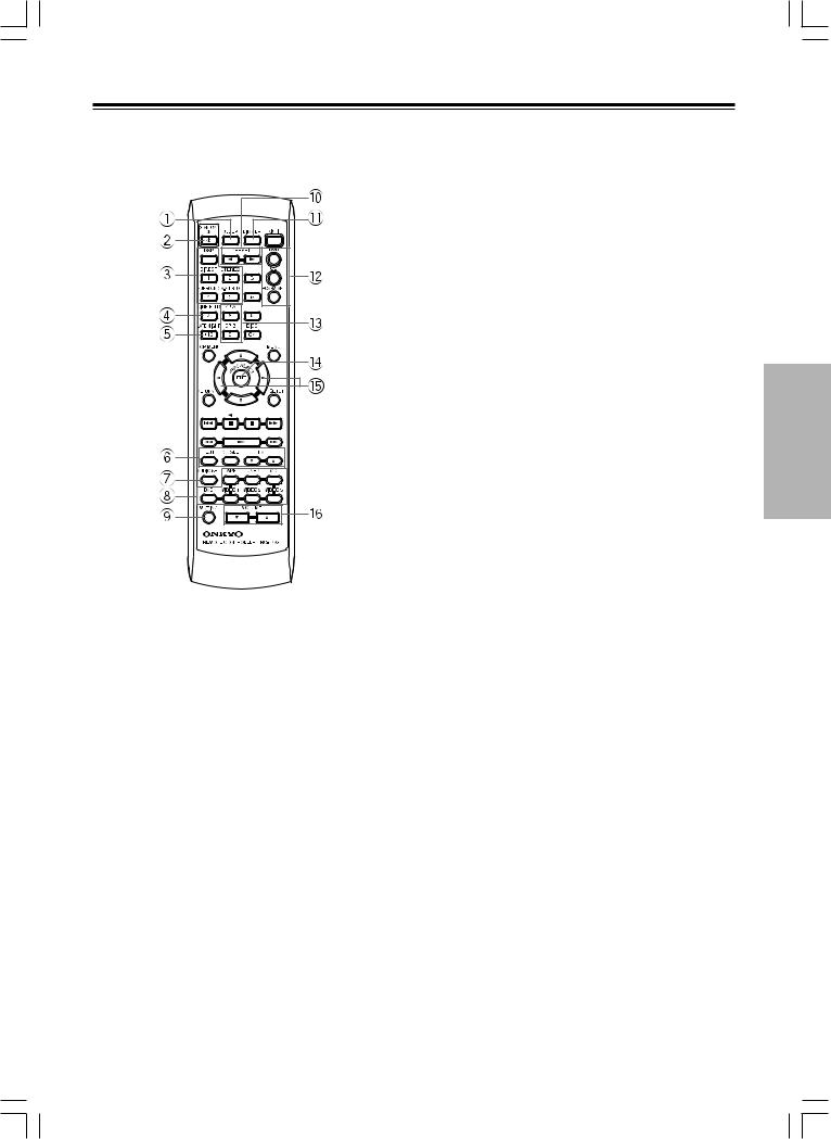
Remote controller
RC-479S
Explanations on this page are for controlling the HT-R320. To operate other components, see “Using the remote controller with your other AV components” on pages 33 through 34.
For operational instructions, refer to the page indicated in brackets.
1SLEEP button [25]
For setting the sleep time.
This button is provided only on the remote controller.
2STANDBY/ON button [17]
Turns on the HT-R320 or put it in standby.
3Listening mode buttons [27, 29]
Press to change the listening mode.
4CINE FLTR button [30]
Press to activate/deactivate Cinema Filter function.
5LATE NIGHT button [30]
Press to change the late night setting.
6TEST/CH SEL/LEVEL  /
/  buttons [20, 26]
For setting the output levels for each speaker.
These buttons are provided only on the remote controller.
7AUDIO SEL button [26, 27]
Press to select an audio input signal format.
8INPUT SELECTOR buttons [17, 21-23, 26, 27, 32]
For selecting the input source.
9MUTING button [24]
Activates the mute function.
This button is provided only on the remote controller.
0PRESET  /
/ button [23]
For selecting a tuner preset channel.
-DIMMER button [25]
For adjusting the brightness of the front display.
=Mode buttons [33-34]
For selecting the component to be operated by the remote controller.
~SP A/SP B buttons [17, 24]
Press to switch the speaker systems.
!AUDIO ADJUST button [30]
Press to adjust bass, treble, late night function and cinema filter function setting.
@ADJUST  /
/ button [30]
Press to adjust the values and parameters of the mode selected using the AUDIO ADJUST, SPEAKER ADJUST or AUDIO SELECTOR button.
#VOLUME  /
/  button [17]
For adjusting the volume.
9
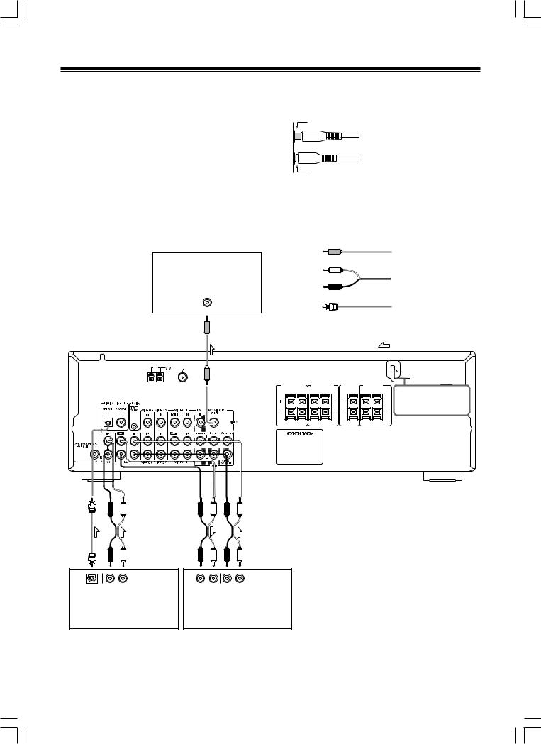
Connecting to audio/video equipment
Before connecting
•Be sure to always refer to the instruction manual that came with the component that you are connecting.
•Do not plug in the power cord until all connections have been made.
•For input jacks, red connectors are used for the right channel, white connectors are used for the left channel, and yellow connectors are used for video connection.
TV monitor or Projector (MONITOR OUT)
VIDEO
IN
AM |
FM |
75 ANTENNA |
•Insert all plugs and connectors securely. Improper connections can result in noise, poor performance, or damage to the equipment.
Improper connection
Inserted completely
•Do not bind audio connection cables with power cords and speaker cables. Doing so may adversely effect the sound quality.
VIDEO
|
|
|
|
Video connection cable |
|
|
|
|
|
(Analog signal) |
|
|
|
Audio (L) |
|
|
|
|
|
Audio (R) |
|
Audio connection cable |
|
|
|
|
(Analog signal) |
||
|
|
|
|
||
|
|
Optical plug |
|
Optical fiber cable |
|
|
|
|
|
||
|
|
|
|
(Digital signal) |
|
|
|
|
|
Signal flow |
|
FRONT |
FRONT |
CENTER |
SURROUND |
|
|
SPEAKERS B |
SPEAKERS A SPEAKER |
SPEAKERS |
AC OUTLET |
||
R L |
R |
L |
R L |
||
DO NOT connect the |
|||||
|
|
|
|
||
|
|
|
|
power cord at this |
|
|
|
|
|
time. |
|
|
|
|
• |
To connect the digital output from a component |
|
|
|
|
|
connected to the TAPE jacks to this unit, use the |
|
|
|
|
|
OPTICAL or COAXIAL input jack. |
|
|
|
|
|
In this case, it is required to change the assignment of |
|
|
|
|
|
digital inputs to input sources by referring to “Setting the |
|
|
|
|
|
digital inputs” on page 21. |
|
|
|
|
• |
The TAPE OUT jack does not output the signal input |
|
|
|
|
|
from the DIGITAL INPUT jack. (The digital signal is not |
|
|
R L |
R L |
R L |
converted into an analog signal.) |
|
DIGITAL |
AUDIO OUT |
|
• To connect the digital output from CD player connected |
||
AUDIO IN |
AUDIO OUT |
to the CD jacks to this unit, use the OPTICAL input jack. |
|||
OUT |
(PLAY) |
(REC) |
(PLAY) |
||
OPTICAL |
|
|
|
To connect the digital output to the COAXIAL input jack |
|
|
|
Cassette Tape deck, MD recorder, |
|||
CD player (CD) |
of this unit, it is required to change the assignment of |
||||
DAT deck, CD recorder (TAPE) |
|||||
|
|
digital inputs to input sources by referring to “Setting the |
|||
|
|
|
|
digital inputs” on page 21. |
|
10

Connecting to audio/video equipment
Video Camera, |
DVD player or component |
|||||
Game Device, etc. |
||||||
with 5.1 ch output (DVD)*1 |
||||||
(VIDEO 3) |
|
|
|
|
||
AUDIO |
VIDEO |
DIGITAL |
VIDEO |
|
AUDIO OUT |
|
OUT |
OUT |
OUT |
OUT |
FRONT |
SURR CENTER SUBWOOFER |
|
R L |
|
COAXIAL |
|
R L |
R L |
|
*2 
Caution
Make sure that the capacity of the other components connected to this unit does not exceed the capacity that is printed on the rear panel (120 watts).
AM |
FM |
75 ANTENNA |
FRONT |
FRONT |
CENTER |
SURROUND |
|
SPEAKERS B |
SPEAKERS A |
SPEAKER |
SPEAKERS |
AC OUTLET |
R |
L |
R |
L |
R |
L |
|
|
|
|
|
DO NOT connect the |
|
|
|
|
|
power cord at this |
|
|
|
|
|
time. |
To connect the digital output from satellite tuner etc. connected to the VIDEO 1, VIDEO 2 or VIDEO 3 jacks to the COAXIAL or OPTICAL  input jack of this unit, it is
  required to change the assignment of digital inputs to input sources by referring to “Setting the digital inputs” on page
  21.
21.
R L |
|
R L |
|
R L |
|
AUDIO |
VIDEO |
AUDIO |
VIDEO |
AUDIO |
VIDEO |
OUT |
OUT |
IN |
IN |
OUT |
OUT |
Video cassette player, |
VCR (VIDEO 1) |
|
|||
Satellite tuner, LD |
|
||||
player*3, etc. (VIDEO 2) |
|
|
|
|
|
Video |
|
Audio (L) |
Audio/video |
|
|
Audio (R) |
connection |
cable |
|
Coaxial plug |
Coaxial cable |
|
|
|
(Digital signal) |
|
Signal flow |
*1 If the DVD player has both 5.1 channel audio outputs and 2 channel audio outputs, and you want to connect the DVD player only using the FRONT L/R jacks on the HT-R320, use the 2 channel audio output jacks on the DVD player.
If the DVD player only has the 2 channel audio outputs, connect it to the FRONT L/R jacks.
*2 To connect the digital output from DVD player connected to the DVD jacks to this unit, use the COAXIAL input jack.
To connect the digital output to the OPTICAL input jack of this unit, it is required to change the assignment of digital inputs to input sources by referring to “Setting the digital inputs” on page 21.
*3 If you have an LD player with AC-3RF output, connect via an AC-3RF demodulator to one of the HT-R320’s DIGITAL INPUT terminals.
11
Positioning speakers/Connecting speakers
Two speaker systems can be connected to the Receiver.
The speaker system A is to be placed in the main room, and the speaker system B is to be placed in a second room.
The speaker system A consists of the FRONT SPEAKERS A (L/R), CENTER SPEAKER, SURROUND SPEAKERS (L/R) and SUBWOOFER.
You can reproduce the sounds such as Dolby surround and DTS surround.
The speaker system B consists of the FRONT SPEAKERS B.
You can reproduce only monaural and stereo sounds.
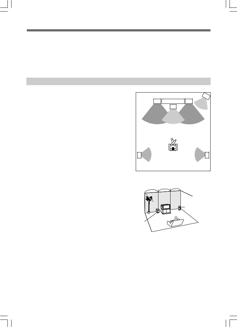
Standard speaker placement of the speaker system A
Speaker placement plays an important role in the reproduction of Surround sound.
The placement of the speakers varies depending on the size of the room and the wall coverings used in the room. The illustration below shows an example of a layout for standard speaker placement. Refer to this example when you position the speakers in order to experience the best of Surround sound.
For ideal Surround effects, all speakers should be installed.
If a center speaker or subwoofer is not connected, the sound from the unused channel is properly distributed to the connected speakers in order to reproduce the best Surround sound possible.
Front
The center speaker reproduces a richer sound image by enhancing the perception of the sound’s source and movement.
The left, right, and center speakers should face the seated listener and be placed at ear level.
Surround
The surround speakers reproduce the feel of a moving sound while creating the sensation of being in the middle of the action.
Place the left and right surround speakers 3 feet (1 meter) above the listener’s ear level and facing toward the sides of the room, making sure that the listener is within the speakers’ dispersion angle.
Subwoofer
When bass sound is reproduced, its volume and quality greatly depend on subwoofer placement. Those characteristics also depends on the shape of your listening room as well as your listening point. Generally speaking, good bass sound is obtained when the subwoofer is placed in the corner of the room or at one-third the length of the room.
Refer to the speakers’ instruction manuals for details.
|
Front |
|
Front |
left speaker |
|
right speaker |
|
|
|
TV/Screen |
Subwoofer |
|
|
|
|
|
|
Center |
|
|
|
speaker |
|
Surround |
|
|
Surround |
left speaker |
|
|
right speaker |
1/3 |
1/3 |
1/3 |
|
|
|
|
Corner |
1/3 room length
12
 Loading...