


 Loading...
7.1ch Home Theater System
HT-S6100
AV Receiver (HT-R667)
Speaker Package (HTP-750X)
Front Speakers (SKF-750XF L/R)
Center Speaker (SKC-750XC)
Surround Speakers (SKM-750XS L/R)
Surround Back Speakers (SKB-750X L/R)
Subwoofer (SKW-750X)
Dock for iPod (DS-A1L)
Instruction Manual
Thank you for purchasing an Onkyo 7.1ch Home Theater System. Please read this manual thoroughly before making connections and plugging in the unit. Following the instructions in this manual will enable you to obtain optimum performance and listening enjoyment from your new 7.1ch Home Theater System.
Please retain this manual for future reference.
Contents
Introduction ..................................... |
2 |
Connection .................................... |
20 |
Turning On & First Time Setup..... 41
Basic Operation |
|
Playing your AV components ....... |
50 |
Using the Tuner............................ |
54 |
DS-A1L Dock for the iPod............ |
57 |
Enjoying the Listening Modes ..... 59
Advanced Operation ..................... |
69 |
Troubleshooting ............................ |
92 |
Specifications................................ |
96 |
En
WARNING:
TO REDUCE THE RISK OF FIRE OR ELECTRIC SHOCK, DO NOT EXPOSE THIS APPARATUS TO RAIN OR MOISTURE.
CAUTION:
TO REDUCE THE RISK OF ELECTRIC SHOCK, DO NOT REMOVE COVER (OR BACK). NO USER-SERVICEABLE PARTS INSIDE. REFER SERVICING TO QUALIFIED SERVICE PERSONNEL.
WARNING |
|
AVIS |
RISK OF ELECTRIC SHOCK |
|
RISQUE DE CHOC ELECTRIQUE |
DO NOT OPEN |
|
NE PAS OUVRIR |
|
|
|
The lightning flash with arrowhead symbol, within an equilateral triangle, is intended to alert the user to the presence of uninsulated “dangerous voltage” within the product’s enclosure that may be of sufficient
magnitude to constitute a risk of electric shock to persons.
The exclamation point within an equilateral triangle is intended to alert the user to the presence of important operating and maintenance (servicing) instructions in the literature accompanying the appliance.
Important Safety Instructions
1.Read these instructions.
2.Keep these instructions.
3.Heed all warnings.
4.Follow all instructions.
5.Do not use this apparatus near water.
6.Clean only with dry cloth.
7.Do not block any ventilation openings. Install in accordance with the manufacturer’s instructions.
8.Do not install near any heat sources such as radiators, heat registers, stoves, or other apparatus (including amplifiers) that produce heat.
9.Do not defeat the safety purpose of the polarized or grounding-type plug. A polarized plug has two blades with one wider than the other. A grounding type plug has two blades and a third grounding prong. The wide blade or the third prong are provided for your safety. If the provided plug does not fit into your outlet, consult an electrician for replacement of the obsolete outlet.
10.Protect the power cord from being walked on or pinched particularly at plugs, convenience receptacles, and the point where they exit from the apparatus.
11.Only use attachments/accessories specified by the manufacturer.
12. Use only with the cart, stand, tripod, bracket, or table specified by the manufacturer, or sold with the apparatus. When a cart is used, use caution when moving the cart/ apparatus combination to avoid injury from tip-over.
13.Unplug this apparatus during lightning storms or when unused for long periods of time.
14.Refer all servicing to qualified service personnel. Servicing is required when the apparatus has been damaged in any way, such as power-supply cord or plug is damaged, liquid has been spilled or objects have fallen into the apparatus, the apparatus has been exposed to rain or moisture, does not operate normally, or has been dropped.
15.Damage Requiring Service
Unplug the apparatus from the wall outlet and refer servicing to qualified service personnel under the following conditions:
A.When the power-supply cord or plug is damaged,
B.If liquid has been spilled, or objects have fallen into the apparatus,
C.If the apparatus has been exposed to rain or water,
D.If the apparatus does not operate normally by following the operating instructions. Adjust only those controls that are covered by the operating instructions as an improper adjustment of other controls may result in damage and will often require extensive work by a qualified technician to restore the apparatus to its normal operation,
E.If the apparatus has been dropped or damaged in any way, and
F.When the apparatus exhibits a distinct change in performance this indicates a need for service.
16.Object and Liquid Entry
Never push objects of any kind into the apparatus through openings as they may touch dangerous voltage points or short-out parts that could result in a fire or electric shock.
The apparatus shall not be exposed to dripping or splashing and no objects filled with liquids, such as vases shall be placed on the apparatus.
Don’t put candles or other burning objects on top of this unit.
17.Batteries
Always consider the environmental issues and follow local regulations when disposing of batteries.
18.If you install the apparatus in a built-in installation, such as a bookcase or rack, ensure that there is adequate ventilation.
Leave 20 cm (8") of free space at the top and sides and 10 cm (4") at the rear. The rear edge of the shelf or board above the apparatus shall be set 10 cm (4") away from the rear panel or wall, creating a flue-like gap for warm air to escape.
2

Precautions
1.Recording Copyright—Unless it’s for personal use only, recording copyrighted material is illegal without the permission of the copyright holder.
2.AC Fuse—The AC fuse inside the unit is not userserviceable. If you cannot turn on the unit, contact your Onkyo dealer.
3.Care—Occasionally you should dust the unit all over with a soft cloth. For stubborn stains, use a soft cloth dampened with a weak solution of mild detergent and water. Dry the unit immediately afterwards with a clean cloth. Don’t use abrasive cloths, thinners, alcohol, or other chemical solvents, because they may damage the finish or remove the panel lettering.
4.Power WARNING
BEFORE PLUGGING IN THE UNIT FOR THE FIRST TIME, READ THE FOLLOWING SECTION CAREFULLY.
AC outlet voltages vary from country to country. Make sure that the voltage in your area meets the voltage requirements printed on the unit’s rear panel (e.g., AC 230 V, 50 Hz or AC 120 V, 60 Hz).
The power cord plug is used to disconnect this unit from the AC power source. Make sure that the plug is readily operable (easily accessible) at all times.
Pressing the [ON/STANDBY] button to select Standby mode does not fully shutdown the unit. If you do not intend to use the unit for an extended period, remove the power cord from the AC outlet.
5.Never Touch this Unit with Wet Hands—Never handle this unit or its power cord while your hands are wet or damp. If water or any other liquid gets inside this unit, have it checked by your Onkyo dealer.
6.Handling Notes
•If you need to transport this unit, use the original packaging to pack it how it was when you originally bought it.
•Do not leave rubber or plastic items on this unit for a long time, because they may leave marks on the case.
•This unit’s top and rear panels may get warm after prolonged use. This is normal.
•If you do not use this unit for a long time, it may not work properly the next time you turn it on, so be sure to use it occasionally.
For U.S. models
FCC Information for User
CAUTION:
The user changes or modifications not expressly approved by the party responsible for compliance could void the user’s authority to operate the equipment.
NOTE:
This equipment has been tested and found to comply with the limits for a Class B digital device, pursuant to Part 15 of the FCC Rules. These limits are designed to provide reasonable protection against harmful interference in a residential installation.
This equipment generates, uses and can radiate radio frequency energy and, if not installed and used in accordance with the instructions, may cause harmful interference to radio communications. However, there is no guarantee that interference will not occur in a particular installation. If this equipment does cause harmful interference to radio or television reception, which can be determined by turning the equipment off and on, the user is encouraged to try to correct the interference by one or more of the following measures:
•Reorient or relocate the receiving antenna.
•Increase the separation between the equipment and receiver.
•Connect the equipment into an outlet on a circuit different from that to which the receiver is connected.
•Consult the dealer or an experienced radio/TV technician for help.
For Canadian Models
NOTE: THIS CLASS B DIGITAL APPARATUS COMPLIES WITH CANADIAN ICES-003.
For models having a power cord with a polarized plug: CAUTION: TO PREVENT ELECTRIC SHOCK, MATCH WIDE BLADE OF PLUG TO WIDE SLOT, FULLY INSERT.
Pour le Modèle Canadien
REMARQUE: CET APPAREIL NUMÉRIQUE DE LA CLASSE B EST CONFORME À LA NORME NMB-003 DU CANADA.
Sur les modèles dont la fiche est polarisée: ATTENTION: POUR ÉVITER LES CHOCS ÉLECTRIQUES, INTRODUIRE LA LAME LA PLUS LARGE DE LA FICHE DANS LA BORNE CORRESPONDANTE DE LA PRISE ET POUSSER JUSQU’AU FOND.
3
Precautions—Continued
For British models
Replacement and mounting of an AC plug on the power supply cord of this unit should be performed only by qualified service personnel.
IMPORTANT
The wires in the mains lead are coloured in accordance with the following code:
Blue: Neutral Brown: Live
As the colours of the wires in the mains lead of this apparatus may not correspond with the coloured markings identifying the terminals in your plug, proceed as follows:
The wire which is coloured blue must be connected to the terminal which is marked with the letter N or coloured black.
The wire which is coloured brown must be connected to the terminal which is marked with the letter L or coloured red.
IMPORTANT
The plug is fitted with an appropriate fuse. If the fuse needs to be replaced, the replacement fuse must be approved by ASTA or BSI to BS1362 and have the same ampere rating as that indicated on the plug. Check for the ASTA mark or the BSI mark on the body of the fuse. If the power cord’s plug is not suitable for your socket outlets, cut it off and fit a suitable plug. Fit a suitable fuse in the plug.
For European Models
Declaration of Conformity
We, ONKYO EUROPE ELECTRONICS GmbH LIEGNITZERSTRASSE 6, 82194 GROEBENZELL, GERMANY
declare in own responsibility, that the ONKYO product described in this instruction manual is in compliance with the corresponding technical standards such as EN60065, EN55013, EN55020 and EN61000-3-2, -3-3.
GROEBENZELL, GERMANY
K. MIYAGI
ONKYO EUROPE ELECTRONICS GmbH
Speaker Precautions
Placement
•The subwoofer cabinet is made out of wood and is therefore sensitive to extreme temperatures and humidity, do not put it in locations subject to direct sunlight or in humid places, such as near an air conditioner, humidifier, bathroom, or kitchen.
•Do not put water or other liquids close to the speakers. If liquid is spilled over the speakers, the drive units may be damaged.
•Speakers should only be placed on sturdy, flat surfaces that are free from vibration. Putting them on uneven or unstable surfaces, where they may fall and cause damage, will affect the sound quality.
•Subwoofer is designed to be used in the upright vertical position only. Do not use it in the horizontal or tilted position.
•If the unit is used near a turntable, CD player or DVD player, howling or slipping of sound may occur. To prevent this, move the unit away from the turntable, CD player or DVD player, otherwise lower the unit’s output level.
Using Close to a TV or Computer
TVs and computer monitors are magnetically sensitive devices and as such are likely to suffer discoloration or picture distortion when conventional speakers are placed nearby. To prevent this, the SKF-750XF and SKC-750XC feature internal magnetic shielding. In some situations, however, discoloration may still be an issue, in which case you should turn off your TV or monitor, wait 15 to 30 minutes, and then turn it back on again. This normally activates the degaussing function, which neutralizes the magnetic field, thereby removing any discoloration effects. If discoloration problems persist, try moving the speakers away from your TV or monitor. Note that discoloration can also be caused by a magnet or demagnetizing tool that’s too close to your TV or monitor.
Do not place SKM-750XS close to TV or a computer monitor because they have no magnetic shield.
Input Signal Warning
The speakers can handle the specified input power when used for normal music reproduction. If any of the following signals are fed to them, even if the input power is within the specified rating, excessive current may flow in the speaker coils, causing burning or wire breakage:
1.Interstation noise from an untuned FM radio.
2.Sound from fast-forwarding a cassette tape.
3.High-pitched sounds generated by an oscillator, electronic musical instrument, and so on.
4.Amplifier oscillation.
5.Special test tones from audio test CDs and so on.
6.Thumps and clicks caused by connecting or disconnecting audio cables (Always turn off your amplifier before connecting or disconnecting cables.)
7.Microphone feedback.
4
Package Contents
Make sure you have the following items:
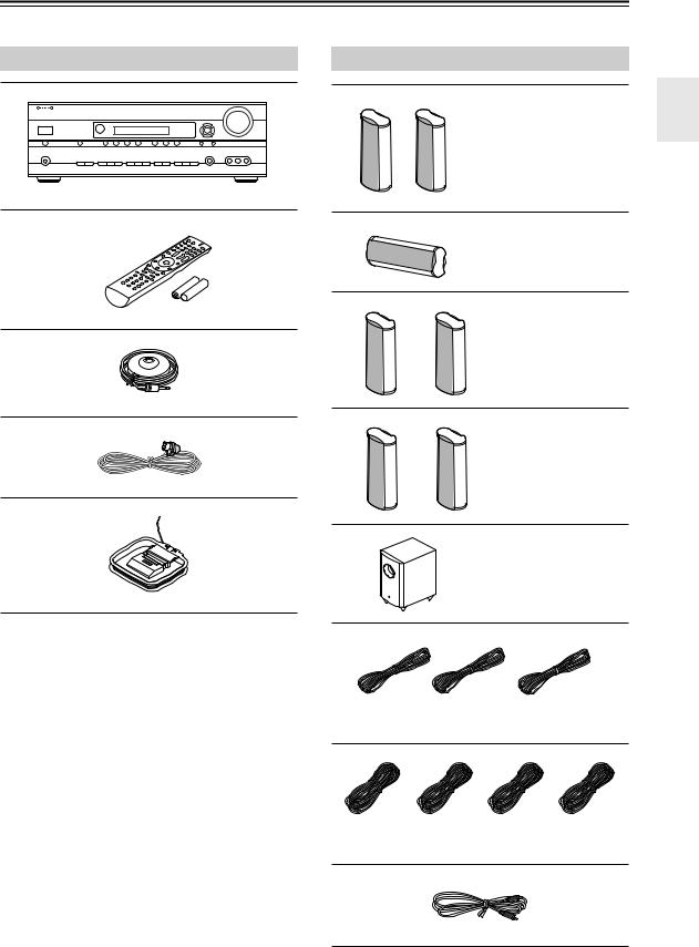
AV Receiver HT-R667
HT-R667
Remote controller and two batteries (AA/R6)
Speaker setup microphone
Indoor FM antenna
AM loop antenna
Speaker Package HTP-750X
Front speakers (SKF-750XF L/R)
Center speaker (SKC-750XC)
Surround speakers (SKM-750XS L/R)
Surround back speakers (SKB-750X L/R)
Subwoofer (SKW-750X)
(Red) |
(White) |
(Green) |
Speaker cable for front speakers 11 ft. and center speaker 10 ft.
|
|
|
|
(Blue) |
(Gray) |
(Brown) |
(Tan) |
Speaker cables for surround and surround back speakers 30 ft.
RCA cable for subwoofer connection 10 ft.
5
Package Contents—Continued
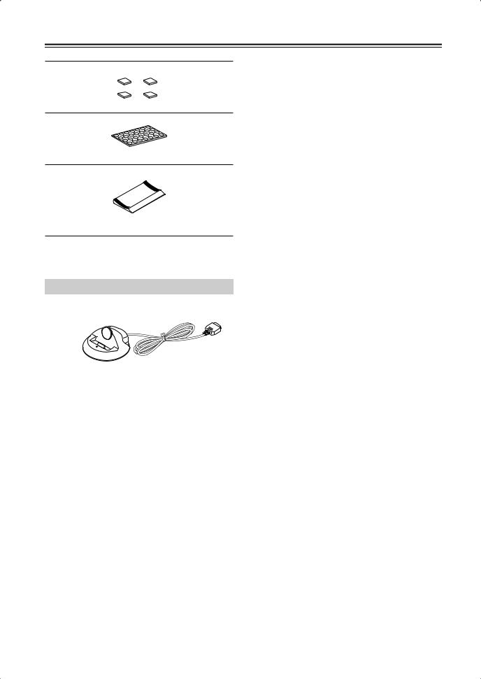
4 floor pads for the subwoofer
Rubber spacers [28] (For the speakers)
Base for horizontal mounting (For the center speaker)
Dock for iPod DS-A1L
*In catalogs and on packaging, the letter at the end of the product name indicates the color. Specifications and operation are the same regardless of color.
6
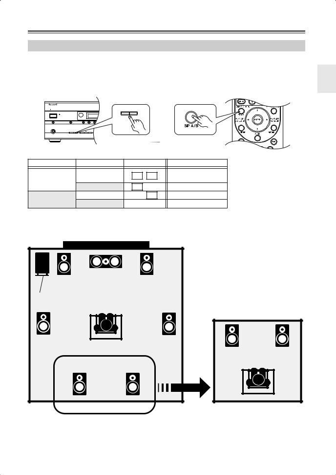
Using Two Sets of Speakers
Speaker Sets A and B
You can use two sets of speakers with the AV receiver: speaker set A and speaker set B. Speaker set A should be used in your main listening room for up to 7.1-channel playback.
*While speaker set B is on, speaker set A is reduced to 5.1-channel playback.
Speaker set B can be used in another room and offers 2-channel stereo playback.
*Only analog input sources are output by speaker set B.
MASTER VOLUME
ON/STANDBY |
|
|
|
|
|
A SPEAKERS |
B |
|
|
|
|
|
|
|
|
TUNING |
PRESET |
|
|
STANDBY |
|
|
|
|
|
|
|
|
|
|
|
|
|
|
|
|
|
or |
|
DOCK |
MULTI CH |
DVD |
VCR/DVR CBL/SAT AUX |
TAPE TUNER |
CD |
SETUP |
RETURN |
|
|
|
|
|
|
|
|
|
|
AUX INPUT |
|
PHONES |
|
|
|
|
|
|
SETUP MIC |
VIDEO L AUDIO R |
|
|
A SPEAKERS B |
TONE |
MOVIE/TV MUSIC GAME |
DISPLAY DIGITAL INPUT |
DIMMER MEMORY TUNING MODE |
|
|
|
|
|
|
|
LISTENING MODE |
|
|
|
|
|
|
|
|
|
|
|
|
|
|
AV RECEIVER HT-R667 |
|
Speaker set A |
|
Speaker set B |
|
|
Indicator |
Output |
|||
|
|
|
On |
|
|
|
A |
B |
Set A: 5.1 channels |
On |
|
|
|
|
|
Set B: 2 channels |
|||
|
|
|
|
|
|
|
|
||
|
|
|
Off |
|
|
|
A |
|
Set A: 7.1 channels |
Off |
|
|
On |
|
|
|
|
B |
Set B: 2 channels |
|
|
Off |
|
|
|
|
|
No sound |
|
|
|
|
|
|
|
|
|
||
Main Room (speaker set A) |
|
Center speaker |
|
Front left |
Front right |
speaker |
speaker |
Subwoofer |
|
Surround |
Surround |
left |
right |
speaker |
speaker |
Surround back |
Surround back |
left speaker |
right speaker |
*While speaker set B is on, the surround back speakers output no sound.
Sub Room (speaker set B)
*Digital input sources are not output by speaker set B. Connect your source component with an analog connection.
7
Features
Amplifier
•130 Watts/Channel @ 8 ohms (FTC)
•WRAT-Wide Range Amplifier Technology (5Hz–100kHz bandwidth)
•Optimum Gain Volume Circuitry
Processing
•HDMI Video Upscaling (Up to 1080i)
•HDMI Video Upconversion
•Dolby TrueHD*1
•DTS-HD Master Audio*2
•Faroudja DCDi Edge Enhancement
•Direct Mode
•Music Optimizer*3 for Compressed Music
•CinemaFILTER
•Non-Scaling Configuration
•A-Form Listening Mode Memory
•24-bit/192kHz D/A Converters
•Powerful and Highly Accurate 32-bit DSP Processing
Connections
•4 HDMI*4 Inputs and 1 Output
•Onkyo RIHD*5 for System Control
•HDTV-Ready Component Video Switching (2 Inputs/ 1 Output)
•4 Digital Inputs (2 Optical/2 Coaxial/4 Assignable)
•3 S-Video Inputs/2 Outputs
•Color-Coded 7.1 Multichannel Inputs
•Subwoofer Pre Outs
•Dedicated DOCK jack for quick and simple DS-A1L Dock connection and iPod playback
Miscellaneous
•40 AM/FM Presets
•Audyssey 2EQ®*6 Room Correction and Speaker Calibration
•Audyssey Dynamic EQ®*6 Loudness Correction
•Crossover Adjustment (40/50/60/80/100/120/150/ 200Hz)
•A/V Sync Control Function (up to 100 ms)
•Theater Dimensional Virtual Surround Function*7
•On-Screen Display
•Preprogrammed 
 -Compatible Remote
Speaker Package HTP-750X
SKF-750XF L/R 2-Way Front Speakers
SKC-750XC Center Speaker
•3-1/8 inch cone woofer ×2
•1 inch Balanced dome tweeter
•Max. input power:110 W
•Magnetically shielded
•8-ohm impedance
•Color-coded speaker terminals and speaker cable
SKM-750XS L/R Full-Range Surround Speakers SKB-750X L/R Full-Range Surround Back Speakers
•3-1/8 inch full-range speaker
•Max. input power:110 W
•8-ohm impedance
•Color-coded speaker terminals and speaker cable
SKW-750X Bass Reflex Powered Subwoofer
•10 inch cone woofer
•Max. power:290 W
Dock DS-A1L
•Play your iPod music through your Onkyo audio system and enjoy great sound
•Control your iPod with your Onkyo remote controller
•Supports all iPod models with an iPod connector, except 3rd Generation iPod models
•Charges your iPod’s battery while you enjoy your music
*1.
Manufactured under license from Dolby Laboratories. Dolby, Pro Logic, and the double-D symbol are trademarks of Dolby Laboratories.
*2.
Manufactured under license under U.S. Patent #’s: 5,451,942; 5,956,674; 5,974,380; 5,978,762; 6,226,616; 6,487,535 & other U.S. and worldwide patents issued & pending. DTS is a registered trademark and the DTS logos, Symbol, DTS-HD and DTS-HD Master Audio are trademarks of DTS, Inc.
“DTS” and “DTS-ES | Neo: 6” are registered trademarks of DTS, Inc. “96/24” is a trademark of DTS, Inc.
*3 Music Optimizer™ is a trademark of Onkyo Corporation.
*4
HDMI, the HDMI logo and High Definition Multimedia Interface are trademarks or registered trademarks of HDMI Licensing, LLC.
8
Features—Continued
*5
RIHD is a trademark of Onkyo Corporation.
*6
Manufactured under license from Audyssey Laboratories. U.S. and foreign patents pending. Audyssey 2EQ and Dynamic EQ are trademarks of Audyssey Laboratories.
*7
Theater-Dimensional is a trademark of Onkyo Corporation.
* iPod is a trademark of Apple Inc., registered in the U.S. and other countries.
*“x.v.Color” is a trademark of Sony Corporation.
This product incorporates copyright protection technology that is protected by U.S. patents and other intellectual property rights. Use of this copyright protection technology must be authorized by Macrovision Corporation, and is intended for home and other limited consumer uses only unless otherwise authorized by Macrovision. Reverse engineering or disassembly is prohibited.
9

Contents
Important Safety Instructions .......................... |
2 |
Precautions ....................................................... |
3 |
Speaker Precautions ........................................ |
4 |
Package Contents ............................................ |
5 |
AV Receiver HT-R667 ........................................... |
5 |
Speaker Package HTP-750X .................................. |
5 |
Dock for iPod DS-A1L ........................................... |
6 |
Using Two Sets of Speakers ........................... |
7 |
Speaker Sets A and B ............................................. |
7 |
Sub Room (speaker set B) ....................................... |
7 |
Main Room (speaker set A) ..................................... |
7 |
Features ............................................................ |
8 |
Speaker Package HTP-750X .................................. |
8 |
Dock DS-A1L ......................................................... |
8 |
Getting to Know the AV Receiver ................. |
12 |
Front Panel ............................................................ |
12 |
Display .................................................................. |
13 |
Rear Panel ............................................................. |
14 |
Speaker Package ............................................ |
16 |
Subwoofer (SKW-750X) ...................................... |
16 |
Front, Center, Surround, and Surround back |
|
speakers (SKF-750XF, SKC-750XC, |
|
SKM-750XS) ..................................................... |
16 |
Remote Controller .......................................... |
17 |
Installing the Batteries .......................................... |
17 |
Using the Remote Controller ................................ |
17 |
Controlling the AV Receiver ................................ |
18 |
Controlling a Dock DS-A1L ................................. |
19 |
Connecting Your Speakers ........................... |
20 |
Enjoying Home Theater ........................................ |
20 |
Connecting Speaker Set A .................................... |
22 |
Connecting Speaker Set B .................................... |
22 |
Center Speaker Base ............................................. |
23 |
Using the Floor Pads for Subwoofer .................... |
23 |
Wall Mounting ...................................................... |
23 |
Connecting Antennas .................................... |
24 |
Connecting the Indoor FM Antenna ..................... |
24 |
Connecting the AM Loop Antenna ...................... |
24 |
Connecting an Outdoor FM Antenna ................... |
25 |
Connecting an Outdoor AM Antenna ................... |
25 |
Connecting Your Components ..................... |
26 |
About AV Connections ........................................ |
26 |
Connecting Audio and Video Signals |
|
to the AV Receiver ............................................. |
27 |
Which Connections Should I Use? ....................... |
27 |
Connecting a TV or Projector ............................... |
29 |
Connecting a DVD player .................................... |
30 |
Connecting a VCR or DVR for Playback ............. |
32 |
Connecting a VCR or DVR for Recording ........... |
33 |
Connecting a Satellite, Cable, or Terrestrial |
|
Set-top box or Other Video Source .................... |
34 |
Connecting Components with HDMI ................... |
35 |
Making HDMI Connections ................................. |
36 |
Connecting a Camcorder, Game Console, |
|
|
or Other Device .................................................. |
|
37 |
Connecting the Supplied DS-A1L Dock ............... |
37 |
|
Connecting a CD Player or Turntable ................... |
38 |
|
Connecting a Cassette, CDR, MiniDisc, or DAT |
|
|
Recorder ............................................................. |
|
39 |
Connecting Onkyo |
Components .................... |
40 |
Connecting the Power Cord .................................. |
40 |
|
Turning On the AV Receiver .......................... |
41 |
|
Turning On and Standby ....................................... |
41 |
|
First Time Setup ............................................. |
|
42 |
Automatic Speaker Setup ...................................... |
42 |
|
HDMI Input Setup ................................................ |
|
46 |
Component Video Input Setup .............................. |
47 |
|
Digital Input Setup ................................................ |
|
47 |
Changing the Input Display .................................. |
48 |
|
Automatic Audio Input Selection Setup ............... |
49 |
|
Playing Your AV Components ...................... |
50 |
|
Basic AV Receiver Operation ............................... |
50 |
|
Common Functions ........................................ |
|
51 |
Setting the Display Brightness .............................. |
51 |
|
Muting the AV Receiver ....................................... |
51 |
|
Using the Sleep Timer .......................................... |
|
51 |
Using Headphones ................................................ |
|
52 |
Displaying Source Information ............................. |
52 |
|
Specifying the Digital Signal Format ................... |
53 |
|
Listening to the Radio |
.................................... |
54 |
Listening to AM/FM Stations ............................... |
54 |
|
Presetting AM/FM Stations .................................. |
56 |
|
DS-A1L Dock for the iPod .............................. |
57 |
|
About the DS-A1L Dock ...................................... |
57 |
|
Compatible iPod models ....................................... |
57 |
|
Putting Your iPod in the Dock .............................. |
57 |
|
Function Overview ................................................ |
|
57 |
Using the Listening Modes ............................ |
59 |
|
Selecting the Listening Modes .............................. |
59 |
|
Listening Modes Available for Each |
|
|
Source Format .................................................... |
|
60 |
About the Listening Modes ................................... |
66 |
|
Recording ........................................................ |
|
68 |
Recording the Input Source .................................. |
68 |
|
Recording from Different AV Sources ................. |
68 |
|
Adjusting the Listening Modes ..................... |
69 |
|
Using the Audio Adjust Settings ........................... |
69 |
|
Using the Audio Settings ...................................... |
71 |
|
Listening Mode Presets |
......................................... |
73 |
Advanced Setup ............................................. |
|
74 |
Speaker Setup ........................................................ |
|
74 |
Source Setup ......................................................... |
|
79 |
Miscellaneous Setup ............................................. |
|
80 |
Hardware Setup ..................................................... |
|
81 |
Lock Setup ............................................................ |
|
83 |
10
Contents—Continued |
|
Controlling Other Components ..................... |
84 |
Preprogrammed Remote Control Codes ............... |
84 |
Entering Remote Control Codes ........................... |
84 |
Resetting the Remote Controller ........................... |
85 |
Controlling a DVD Player, or DVD Recorder ...... |
86 |
Controlling a VCR, or PVR .................................. |
87 |
Controlling a Satellite Receiver or Cable |
|
Receiver .............................................................. |
88 |
Controlling a CD Player, CD Recorder, |
|
or MD Player ...................................................... |
89 |
Controlling a Cassette Recorder ............................ |
90 |
Controlling a TV ................................................... |
91 |
Troubleshooting ............................................. |
92 |
Specifications ................................................. |
96 |
7.1ch Home Theater Speaker Package .................. |
97 |
Dock DS-A1L ....................................................... |
97 |
Video Resolution Chart .................................. |
98 |
Onscreen Setup Menu Map ............................ |
99 |
*To reset the AV receiver to its factory defaults, turn it on and, while holding down the [VCR/DVR] button, press the [ON/STANDBY] button (see
page 92).
11
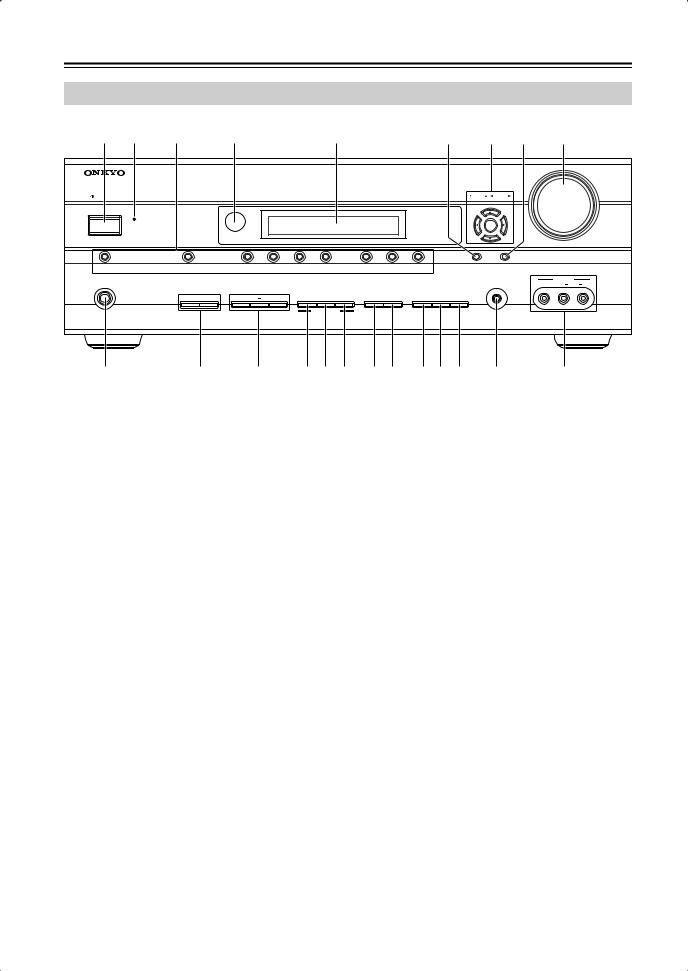
Getting to Know the AV Receiver
Front Panel
1 |
2 |
3 |
4 |
5 |
6 |
7 |
8 |
9 |
|
|
|
|
|
|
|
|
MASTER VOLUME |
ON/STANDBY |
|
|
|
|
|
TUNING PRESET |
|
|
|
STANDBY |
|
|
|
|
|
|
|
|
|
|
|
|
|
ENTER |
|
|
DOCK |
MULTI CH |
DVD |
VCR/DVR |
CBL/SAT |
AUX |
|
TAPE |
TUNER |
CD |
SETUP |
RETURN |
|
|
|
|
|
|
|
|
|
|
|
|
|
|
|
|
|
|
|
|
AUX INPUT |
|
|
|
PHONES |
|
|
|
|
|
|
|
|
|
|
|
SETUP MIC |
VIDEO |
L |
AUDIO |
R |
|
|
A |
SPEAKERS B |
TONE |
|
MOVIE/TV |
MUSIC |
GAME |
DISPLAY |
DIGITAL INPUT |
DIMMER |
MEMORY TUNING MODE |
|
|
|
|
|
|
|
|
|
|
|
LISTENING MODE |
|
|
|
|
CLEAR |
|
|
|
|
|
|
|
|
|
|
|
|
|
|
|
|
|
|
|
|
|
|
AV RECEIVER |
HT-R667 |
|
J |
|
K L M N O P Q RS T U |
|
V |
|
|
|||||||||||
The actual front panel has various logos printed on it. They are not shown here for clarity.
The page numbers in parentheses show where you can find the main explanation for each item.
AON/STANDBY button (41)
Sets the AV receiver to On or Standby.
BSTANDBY indicator (41)
Lights up when the AV receiver is on Standby and flashes while a signal is being received from the remote controller.
CInput selector buttons (50)
Select the following input sources: DVD, VCR/DVR, CBL/SAT, AUX, TAPE, TUNER, CD, DOCK.
The [MULTI CH] button selects the multichannel DVD input.
DRemote-control sensor (17)
Receives control signals from the remote controller.
EDisplay
See “Display” on page 13.
FSETUP button
Opens and closes the setup menus.
GTUNING, PRESET, Arrow, and ENTER buttons
When AM or FM is selected, the TUNING [ ]
]
[ ] buttons are used for radio tuning, and the PRESET [
 ] [
] [ ] buttons are used to select radio presets (see page 56). With the setup menus, they work as arrow buttons and are used to select and set items. The ENTER button is also used with the setup menus.
HRETURN button
Selects the previously displayed setup menu.
IMASTER VOLUME control (50)
Sets the volume of the AV receiver to Min, 1 through 79, or Max.
JPHONES jack (52)
This 1/4-inch phone jack is for connecting a standard pair of stereo headphones for private listening.
KSPEAKERS A B buttons
Turn speaker set A and B on or off.
LTONE, –, and + buttons (71)
Used to adjust the tone (bass and treble).
MMOVIE/TV button (59)
Selects the listening modes intended for use with movies and TV.
NMUSIC button (59)
Selects the listening modes intended for use with music.
OGAME button (59)
Selects the listening modes intended for use with video games.
PDISPLAY button (52)
Displays various information about the currently selected input source.
QDIGITAL INPUT button (49)
Used to assign digital inputs to input selectors.
RDIMMER button (51)
Adjusts the display brightness.
SMEMORY button (56)
Used when storing or deleting radio presets.
12
Getting to Know the AV Receiver—Continued
T TUNING MODE button (54) |
V AUX INPUT (37, 68) |
|
Selects the Auto or Manual tuning mode for AM |
Used to connect a camcorder, game console, and so |
|
and FM radio. |
on. There are input jacks for composite video and |
|
U SETUP MIC (42) |
analog audio. |
|
|
|
|
The automatic speaker setup microphone connects |
|
|
here. |
|
|
|
|
|
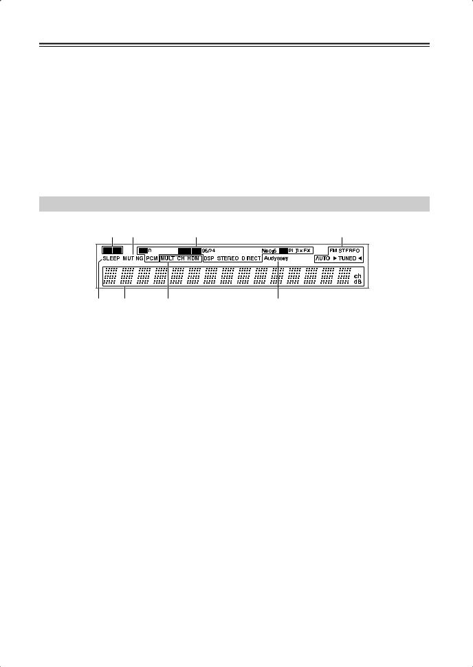
Display
1 2 |
3 |
4 |
||
|
|
|
|
|
|
|
|
|
|
5 |
6 |
7 |
8 |
For detailed information, see the pages in parentheses.
1A and B speaker indicators (7, 50)
Indicator A lights up when speaker set A is on. Indicator B lights up when speaker set B is on.
2MUTING indicator (51)
Flashes while the AV receiver is muted.
3Listening mode and format indicators (59)
Show the selected listening mode and audio input signal format.
4Tuning indicators (54)
FM STEREO (54): Lights up when tuned to a stereo FM station.
AUTO (54): Lights up when Auto Tuning mode is selected for AM or FM radio. Goes off when Manual Tuning mode is selected.
TUNED (54): Lights up when tuned to a radio station.
5SLEEP indicator (51)
Lights up when the Sleep function has been set.
6Message area
Displays various information.
7Audio input indicators
Indicate the type of audio input that’s selected as the audio source: MULTI CH, or HDMI.
8Audyssey indicator
Lights up during automatic speaker setup.
13
Getting to Know the AV Receiver—Continued
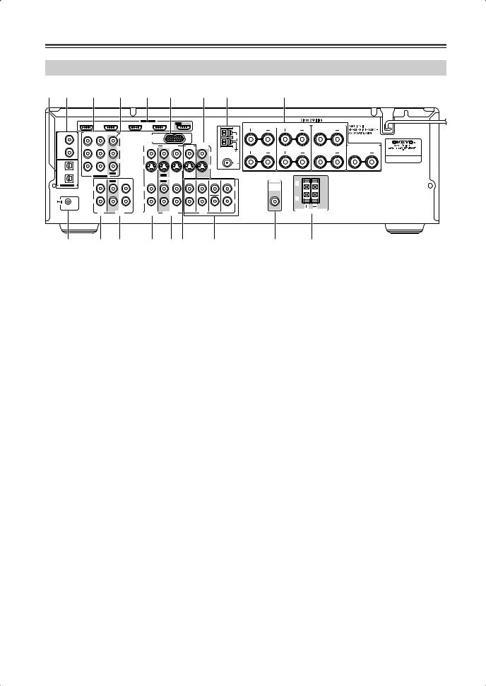
Rear Panel
1 2 |
3 |
4 |
|
5 |
|
6 |
7 |
8 |
9 |
|
|
|
|
|
HDMI |
|
|
|
|
|
|
|
|
|
|
ASSIGNABLE |
|
|
|
|
|
|
|
IN 4 |
IN 3 (CBL/SAT) |
IN 2 |
(VCR/DVR) |
IN 1 |
(DVD) |
OUT |
SURR BACK SPEAKERS |
SURR SPEAKERS |
FRONT SPEAKERS A |
|
|
|
|
|
|
|
|
|||
DIGITAL IN |
COMPONENT VIDEO |
|
|
|
|
|
|
|
L |
L |
|
|
|
|
|
|
|
|
|
|
|||
|
|
|
Y |
DOCK |
|
|
|
|
AM |
|
|
1 |
|
|
|
(for DS-A1L) |
|
|
|
|
|
|
|
(DVD) |
|
|
|
|
|
|
|
|
|
|
|
COAXIAL |
|
|
|
CBL/SAT |
VCR/DVR |
DVD |
MONITOR |
|
|
CENTER SPEAKER |
|
|
|
CB/PB |
OUT |
|
|
|
|||||
2 |
|
|
|
V |
|
|
|
|
V |
R |
R |
(CBL/SAT) |
|
|
|
|
|
|
|
|
|
||
|
|
|
|
|
|
|
|
|
ANTENNA |
|
|
|
|
|
CR/PR |
|
|
|
|
|
FM |
|
|
1 |
|
|
|
S |
|
|
|
|
75 |
|
|
(VCR/DVR) |
|
|
|
|
|
|
|
S |
|
|
|
OPTICAL |
IN 2 (CBL/SAT) IN 1(DVD) |
OUT |
|
|
|
|
|
|
|
|
|
|
|
IN |
OUT |
IN |
IN |
|
|
|
|
||
2 |
ASSIGNABLE |
|
|
|
|
|
|
||||
|
|
|
|
|
|
|
|
|
|
PRE OUT |
|
(CD) |
IN |
OUT |
IN |
IN |
OUT |
IN |
FRONT |
SURR |
CENTER SURR BACK |
|
|
|
|
L |
|||||||||
ASSIGNABLE |
|
|
|
|
|
|
|
|
|
|
|
|
|
|
|
|
|
|
|
|
|
SUB |
|
|
L |
|
|
L |
|
|
|
|
L |
|
WOOFER |
|
R |
|
|
R |
|
|
|
|
R |
|
R |
|
|
|
|
|
|
|
|
|
|||
REMOTE |
|
|
|
|
|
|
|
|
SUB |
|
|
CONTROL |
|
|
|
|
|
|
|
|
|
|
|
|
CD |
|
TAPE |
CBL/SAT |
VCR/DVR |
|
DVD |
WOOFER |
|
FRONT SPEAKERS B |
|
|
|
|
|
|
|
||||||
J K L M NO P |
Q R |
ADIGITAL IN OPTICAL 1 and 2
These optical digital audio inputs are for connecting components with an optical digital audio output, such as a CD player or DVD player. They’re assignable, which means you can assign each one to an input selector to suit your setup. See “Digital Input Setup” on page 47.
BDIGITAL IN COAXIAL 1 and 2
These coaxial digital audio inputs are for connecting components with a coaxial digital audio output, such as a CD player or DVD player. They’re assignable, which means you can assign each one to an input selector to suit your setup. See “Digital Input Setup” on page 47.
CCOMPONENT VIDEO IN 1 and 2
These RCA component video inputs are for connecting components with a component video output, such as a DVD player, DVD recorder, or DVR (digital video recorder). They’re assignable, which means you can assign each one to an input selector to suit your setup. See “Component Video Input Setup” on page 47.
DCOMPONENT VIDEO OUT
This RCA component video output is for connecting a TV or projector with a component video input.
EHDMI IN 1–4 and OUT
HDMI (High Definition Multimedia Interface) connections carry digital audio and digital video.
The HDMI inputs are for connecting components with an HDMI output, such as a DVD player, DVD recorder, or DVR (digital video recorder). They’re assignable, which means you can assign each one to an input selector to suit your setup. See “HDMI Input Setup” on page 46.
The HDMI outputs are for connecting a TV or projector with an HDMI input.
FDOCK
This jack is for connecting the supplied DS-A1L Dock.
GMONITOR OUT
The S-Video or composite video jack should be connected to a video input on your TV or projector.
HAM and FM ANTENNA
The AM push terminals are for connecting an AM antenna. The FM jack is for connecting an FM antenna.
IFRONT L/R, CENTER, SURR L/R, and SURR BACK L/R SPEAKERS
These terminal posts are for connecting the front speakers, center, surround, and surround back speakers.
J
 REMOTE CONTROL
This 
 (Remote Interactive) jack can be connected to the
 jack on another
 -capable Onkyo component for remote and system control.
To use 
 , you must make an analog audio connection (RCA) between the AV receiver and the other component, even if they are connected digitally.
KCD IN
This analog audio input is for connecting a CD player’s analog audio output.
LTAPE IN/OUT
These analog audio input and output jacks are for connecting a recorder with an analog audio input and output, such as a cassette deck, MD recorder, etc.
14

Getting to Know the AV Receiver—Continued
MCBL/SAT IN
A cable or satellite receiver can be connected here. There are S-Video and composite video input jacks for connecting the video signal, and there are analog audio input jacks for connecting the audio signal.
NVCR/DVR IN/OUT
A video component, such as a VCR or DVR, can be connected here for recording and playback. There are S-Video and composite video input and output jacks for connecting the video signal, and there are analog audio input jacks for connecting the audio signal.
ODVD IN
This input is for connecting a DVD player. There are S-Video and composite video input jacks for connecting the video signal.
PDVD FRONT L/R, CENTER, SUBWOOFER, SURR L/R, and SURR BACK L/R
This analog multichannel input is for connecting a component with a 5.1/7.1-channel analog audio output, such as a DVD player, DVD-Audio or SACD-capable player, or an MPEG decoder.
QSUBWOOFER PRE OUT
This analog audio output can be connected to a powered subwoofer.
RFRONT SPEAKERS B
These push terminals are for connecting speaker set B.
See pages 20–40 for hookup information.
15
Speaker Package
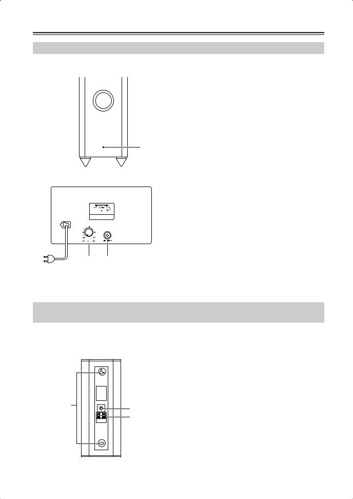
Subwoofer (SKW-750X)
For detailed information, see the pages in parentheses. |
|
|
||
■ Front |
A STANDBY/ON indicator |
|||
|
|
|
Red: |
Subwoofer in standby mode |
|
|
|
||
|
|
|
Blue: |
Subwoofer on |
■ Rear


 X
X
2 3
To AC outlet
With the Auto Standby function, the SKW-750X automatically turns on when an input signal is detected in Standby mode. When there’s no input signal for a while, the SKW-750X automatically enters Standby mode.
B OUTPUT LEVEL control (50)
1
This control is used to adjust the volume of the subwoofer.
CLINE INPUT (22)
This RCA input should be connected to the subwoofer pre out on your AV receiver, amp, or other receiver with supplied RCA cable.
Note:
The Auto Standby function turns the subwoofer on when the input signal exceeds a certain level. If the Auto Standby function does not work reliably, try slightly increasing or decreasing the subwoofer output level on the AV receiver (page 81).
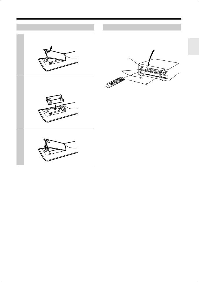
Front, Center, Surround, and Surround back speakers (SKF-750XF, SKC-750XC, SKM-750XS, SKB-750X)
■Rear
SKF-750XF/SKM-750XS/SKC-750XC/SKB-750X
1Keyhole slots
These keyhole slots can be used to wall-mount the speaker. See page 23 for mounting instructions.
2 Speaker terminals
|
|
These push terminals are for connecting the speaker |
|
|
|
to your AV Receiver, amp, or other receiver with the |
|
|
|
supplied speaker cables. The supplied speaker |
|
|
|
cables are color-coded for easy identification. Sim- |
|
|
|
ply connect each cable to the same-colored positive |
|
1 |
|
speaker terminal. |
|
3 |
3 Speaker mount/bracket inserts |
||
|
|||
|
2 |
These threaded inserts can be used to attach the |
|
|
|
speaker either horizontally or vertically to a speaker |
|
|
|
mount or bracket. |
|
|
|
Note: |
|
|
|
Use commercially available 1/4" screws to attach |
|
|
|
the speaker to a speaker mount or bracket. |
16
Remote Controller
Installing the Batteries
1 To open the battery compartment, press the small lever and remove the cover.
2 Insert the two supplied batteries (AA/R6) in accordance with the polarity diagram inside the battery compartment.
3 Replace the cover and push it shut.
Notes:
•If the remote controller doesn’t work reliably, try replacing the batteries.
•Don’t mix new and old batteries or different types of batteries.
•If you intend not to use the remote controller for a long time, remove the batteries to prevent damage from leakage or corrosion.
•Expired batteries should be removed as soon as possible to prevent damage from leakage or corrosion.
Using the Remote Controller
When using the remote controller, point it toward the AV receiver’s remote control sensor, as shown below.
Remote control sensor
STANDBY indicator |
AV receiver |
30˚
30˚
Approx. 16 ft.
Notes:
•The remote controller may not work reliably if the AV receiver is subjected to bright light, such as direct sunlight or inverter-type fluorescent lights. Keep this in mind when installing.
•If another remote controller of the same type is used in the same room, or the AV receiver is installed close to equipment that uses infrared rays, the remote controller may not work reliably.
•Don’t put anything on top of the remote controller, such as a book or magazine, because a button may be pressed continuously, thereby draining the batteries.
•The remote controller may not work reliably if the AV receiver is installed in a rack behind colored glass doors. Keep this in mind when installing.
•The remote controller will not work if there’s an obstacle between it and the AV receiver’s remote control sensor.
17
Remote Controller—Continued
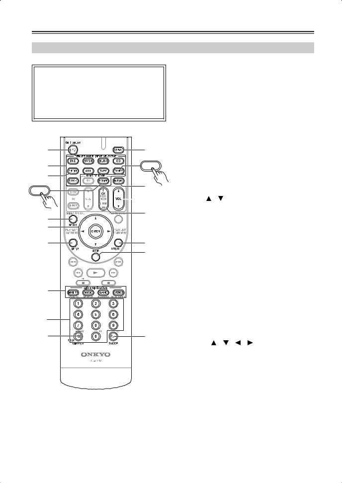
Controlling the AV Receiver
■ Controlling the receiver
To control the AV receiver, press the [RECEIVER] REMOTE MODE button to select Receiver mode first.
You can also use the remote controller to control your DVD player, CD player, and other components. See page 84 for more details.
CMULTI CH button (50)
Selects the multichannel DVD input.
DSP A/B button (50)
Used to turn speaker set A or B on or off.
EArrow [ ]/[
]/[ ]/[
]/[ ]/[
]/[ ] and ENTER buttons
Used to select and adjust settings.
FSETUP button
Used to change settings.
|
|
G |
A |
94 |
H |
|
||
2 |
TUNER |
I |
|
||
3 |
|
J |
|
J |
|
RECEIVER |
|
|
|
|
LISTENING MODE buttons (59)
Used to select the listening modes.
DIMMER button (51)
Adjusts the display brightness.
DISPLAY button (52)
Displays information about the current input source.
MUTING button (51)
Mutes or unmutes the AV receiver.
|
K |
K VOL [ ]/[ ] button (50) |
|
|
|
Adjusts the volume of the AV receiver regardless of |
|
4 |
5 |
the currently selected remote controller mode. |
|
|
L RETURN button |
||
15 |
|
||
|
Returns to the previous display when changing set- |
||
|
|
||
6 |
L |
tings. |
|
M AUDIO button (71) |
|||
|
M |
||
|
Used to change audio settings. |
||
|
|
||
|
|
When the Audio TV Out setting is set to On |
|
|
|
(page 82), this button is disabled. |
|
|
|
N SLEEP button (51) |
|
7 |
|
Used with the Sleep function. |
|
|
|
||
|
|
■ Controlling the tuner |
|
|
To control the AV receiver’s tuner, press the [TUNER] |
|
2 |
|
(or [RECEIVER]) REMOTE MODE button. You can |
|
|
|
select AM or FM by pressing the [TUNER] button |
|
38 |
N |
repeatedly. |
|
1 Arrow [ ]/[ ]/[ ]/[ ] buttons |
|||
|
|
||
|
|
Used to tune into radio stations and select preset. |
|
|
|
2 Number buttons (55) |
For detailed information, see the pages in parentheses.
AON/STANDBY button (41)
Sets the AV receiver to On or Standby.
BREMOTE MODE/INPUT SELECTOR buttons (19, 50, 86–91)
Selects the remote controller modes and the input sources.
Used to select AM and FM radio stations and preset stations directly.
3D.TUN button (55)
Selects the Direct tuning mode.
4DISPLAY button(55)
Displays information about the band, frequency, preset number, and so on.
5CH +/– button (56)
Selects radio presets.
Note:
•An Onkyo cassette recorder connected via 
 can also be controlled in Receiver (see page 90).
18
Remote Controller—Continued
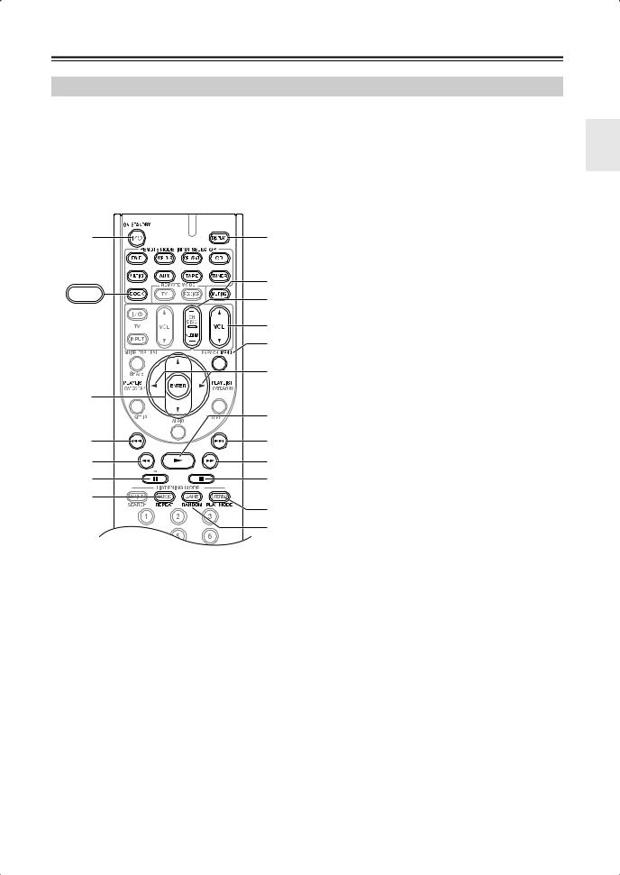
Controlling a Dock DS-A1L
To control your iPod when it’s seated in the supplied DS-A1L Dock, which is connected to the HT-R667’s DOCK jack, press the [DOCK] REMOTE MODE button.
See page 37 for details on connecting the DS-A1L Dock. To control an RI Dock other than the DS-A1L, see “Controlling Other Components” on page 84.
A |
7 |
|
8 |
DOCK |
9 |
|
|
|
J |
|
K |
|
L |
2 |
|
|
M |
3 |
N |
4 |
O |
5 |
P |
6 |
Q |
|
R
*With some components, certain buttons may not work as expected, and some may not work at all.
AON/STANDBY button
Turns the iPod on or off.
Notes:
•Your iPod may not respond the first time you press this button, in which case you should press it again. This is because the remote controller transmits the On and Standby commands alternately, so if your iPod is already on, it will remain on when the remote controller transmits an On command. Similarly, if your iPod is already off, it will remain off when the remote controller transmits an Off command.
BArrow [ ]/[
]/[ ] and ENTER buttons
Used to navigate menus and select items.
CPrevious [ ] button
Restarts the current song. Press it twice to select the previous song.
DRewind [ ] button
Press and hold to rewind.
EPause [ 
 ] button
Pauses playback.
FREPEAT button
Used with the repeat function.
GDISPLAY button
Turns on the backlight for 30 seconds.
HMUTING button (51)
Mutes or unmutes the AV receiver.
IALBUM +/– button
Selects the next or previous album.
JVOL [ ]/[
]/[ ] button (50)
Adjusts the volume of the AV receiver.
KMENU button
Displays a menu.
LPLAYLIST [ ]/[
]/[ ] buttons
Selects the previous or next playlist on the iPod.
MPlay [ ] button
Starts playback. If the component is off, it will turn on automatically.
NNext [
 ] button
Selects the next song.
OFast Forward [ ] button
Press and hold to fast forward.
PStop [ ] button
Stops playback and displays a menu.
QPLAY MODE button
Selects play modes on components with selectable play modes.
RRANDOM button
Used with the shuffle function.
19
Connecting Your Speakers
Enjoying Home Theater
Thanks to the AV receiver’s superb capabilities, you can enjoy surround sound with a real sense of movement in your own home—just like being in a movie theater or concert hall. You can enjoy DVDs featuring Dolby Digital or DTS. With analog or digital TV, you can enjoy Dolby Pro Logic IIx, DTS Neo:6, or Onkyo’s original DSP listening modes.
Front left and right speakers (SKF-750XF)
These output the main sound. Their role in a home theater is to provide a solid anchor for the sound image. They should be positioned facing the listener at about ear level, and equally spaced from the TV. Angle them inward slightly so as to create a triangle, with the listener at the apex.
Center speaker (SKC-750XC)
This speaker enhances the front left and right speakers, making sound movements distinct and providing a full sound image. For movies it’s used mainly for dialog.
Position it close to your TV (preferably on top) facing forward at about ear level, or at the same height as the front left and right speakers.
Surround left and right speakers (SKM-750XS)
These speakers are used for precise sound positioning and to add realistic ambience.
Position them at the sides of the listener, or slightly behind, about 2–3 feet (60–100 cm) above ear level. Ideally they should be equally spaced from the listener.
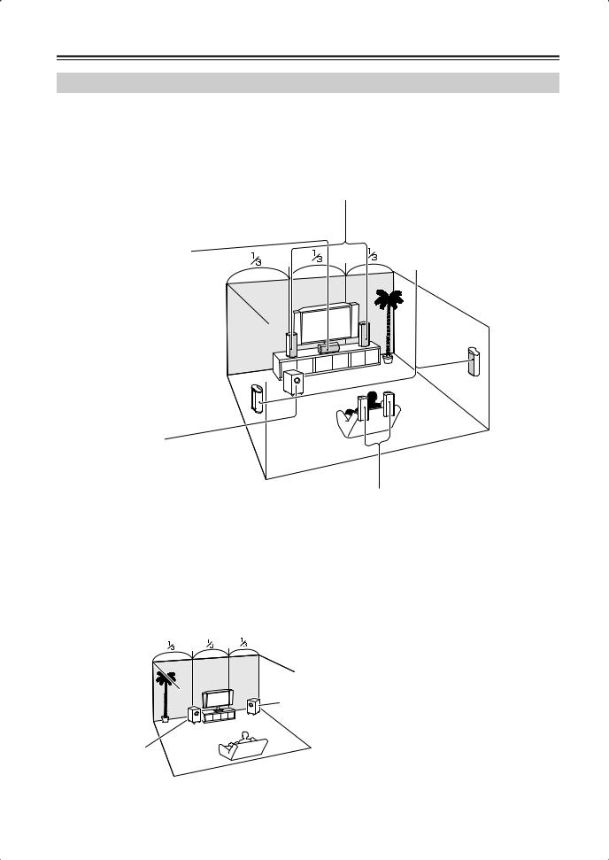
Subwoofer (SKW-750X)
The subwoofer handles the bass sounds of the LFE (Low-Frequency Effects) channel. The volume and quality of the bass output from your subwoofer will depend on its position, the shape of your listening room, and your listening position. In general, a good bass sound can be obtained by installing the subwoofer in a front corner, or at one-third the way along the front wall, as shown.
Tip: To find the best position for your subwoofer, while playing a movie or some music with good bass, experiment by placing your subwoofer at various positions within the room and choose the one that provides the most satisfying results.
Corner position
1/3 of wall position
Surround back left and right speakers (SKB-750X)
These speakers are necessary to enjoy Dolby Digital EX, DTS-ES Matrix, DTS-ES Discrete, etc. They enhance the realism of surround sound and improve sound localization behind the listener. Position them behind the listener about 2–3 feet (60–100 cm) above ear level.
20
Connecting Your Speakers—Continued
Speaker Configuration
For 7.1-channel surround-sound playback, you need seven speakers and a powered subwoofer.
The following table shows which channels you should use based on the number of speakers you have.
Number of speakers: |
2 |
3 |
4 |
5 |
6 |
7 |
|
|
|
|
|
|
|
Front left |
|
|
|
|
|
|
|
|
|
|
|
|
|
Front right |
|
|
|
|
|
|
|
|
|
|
|
|
|
Center |
|
|
|
|
|
|
|
|
|
|
|
|
|
Surround left |
|
|
|
|
|
|
|
|
|
|
|
|
|
Surround right |
|
|
|
|
|
|
|
|
|
|
|
|
|
Surround back* |
|
|
|
|
|
|
|
|
|
|
|
|
|
Surround back left |
|
|
|
|
|
|
|
|
|
|
|
|
|
Surround back right |
|
|
|
|
|
|
|
|
|
|
|
|
|
*If you’re using only one surround back speaker, connect it to the SURR BACK L terminals.
No matter how many speakers you use, a powered subwoofer is recommended for a powerful and solid bass.
To get the best from your surround-sound system, you must set the speaker settings. You can do this automatically (see page 42) or manually (see page 74).
Speaker Connection Precautions
Read the following before connecting your speakers:
•You can connect speakers with an impedance of between 8 and 16 ohms. If you use speakers with a lower impedance, and use the amplifier at high volume levels for a long period of time, the built-in amp protection circuit may be activated.
•Disconnect the power cord from the wall outlet before making any connections.
•Read the instructions supplied with your speakers.
•Pay close attention to speaker wiring polarity. Connect positive (+) terminals to only positive (+) terminals, and negative (–) terminals to only negative (–) terminals. If you get them the wrong way around, the sound will be out of phase and will sound unnatural.
•Unnecessarily long or very thin speaker cables may affect the sound quality and should be avoided.
•Be careful not to short the
positive and negative wires. Doing so may damage the AV receiver.
• Don’t connect more than one cable to each speaker terminal. Doing so may damage the AV receiver.
• Don’t connect a speaker to several terminals.
21

Connecting Your Speakers—Continued
Connecting Speaker Set A |
|
Connecting Speaker Set B |
|
|
|
1 |
Strip 5/8" of insulation |
5/8" |
|
||
|
from the ends of the |
|
|
|
|
|
speaker cables, and twist |
|
|
the bare wires tightly, as |
|
|
shown. |
|
2 Unscrew the terminal. Fully insert the bare wire, making sure that it’s touching the threaded shaft in the center. Screw the terminal tight.
1 |
Strip 3/8" of insulation |
3/8" |
|
||
|
from the ends of the |
|
|
|
|
|
speaker cables, and twist |
|
|
the bare wires tightly, as |
|
|
shown. |
|
2 While pressing the lever, insert |
|
|
|
the wire into the hole, and then |
|
|
release the lever. |
|
|
Make sure that the terminals are |
|
|
gripping the bare wires, not the |
|
|
insulation. |
|
Note:
While speaker set B is on, speaker set A is reduced to 5.1-channel playback.
|
|
Speaker Set A |
|
|
|
|
|
Front right |
Center |
Front left |
|
speaker |
speaker |
speaker |
|
The following illustration shows which speaker should be connected to each pair of terminals.
If you’re using only one surround back speaker, connect it to the left (L) SURR BACK SPEAKERS terminals.
|
HDMI |
|
|
|
|
|
|
ASSIGNABLE |
|
|
|
|
|
IN 3 (CBL/SAT) |
IN 2 (VCR/DVR) |
IN 1 (DVD) |
OUT |
SURR BACK SPEAKERS |
SURR SPEAKERS |
FRONT SPEAKERS A |
NENT VIDEO |
|
|
|
L |
|
L |
|
|
|
|
|
|
|
Y |
|
DOCK |
|
AM |
|
|
|
(for DS-A1L) |
|
|
|
|
|
|
|
CB/PB |
CBL/SAT |
VCR/DVR |
DVD |
MONITOR |
|
|
|
CENTER SPEAKER |
|
|
|
|
|
|
|
|
|
OUT |
|
|
|
|
|
|
|
|
|
|
V |
|
|
|
|
V |
R |
|
R |
|
|
|
|
|
|
|
|
|
|
ANTENNA |
|
|
|
|
|
|
|
CR/PR |
|
|
|
|
|
FM |
|
|
|
|
|
|
|
|
S |
|
|
|
|
75 |
|
|
|
|
|
|
|
|
|
|
|
|
S |
|
|
|
|
|
|
N 1(DVD) |
OUT |
|
IN |
OUT |
IN |
IN |
|
|
|
|
SURR BACK SPEAKERS |
SURR SPEAKERS |
FRONT SPEAKERS A |
SIGNABLE |
|
|
|
|
|
|
|
|
|
||||
IN |
OUT |
IN |
IN |
OUT |
IN |
FRONT |
SURR |
CENTER SURR BACK |
PRE OUT |
L |
|
|
|
SUB |
L |
|
L |
||||||||||
|
|
|
|
|
|
|
|
|
|
|
|||
|
|
|
L |
|
|
|
|
L |
WOOFER |
|
|
|
|
|
|
|
R |
|
|
|
|
R |
|
R |
|
|
|
|
|
|
|
|
|
|
|
|
|
|
|
||
CD |
|
TAPE |
CBL/SAT |
VCR/DVR |
|
DVD |
SUB |
|
FRONT SPEAKERS B |
|
|
CENTER |
|
|
|
WOOFER |
|
|
|
SPEAKER |
|||||||
R 

 R
R
|
|
|
|
|
|
|
|
|
|
|
|
|
|
|
|
|
|
|
|
|
|
|
|
|
|
|
|
|
|
|
|
|
|
|
|
|
|
|
|
|
|
|
|
|
|
|
|
|
|
|
|
|
|
|
|
|
|
|
|
|
|
|
|
|
|
|
|
|
|
|
|
|
|
|
|
|
|
|
|
|
|
|
|
|
|
|
|
|
|
|
|
|
|
|
|
|
|
|
|
|
|
|
|
|
|
|
|
|
|
|
|
|
|
|
|
|
|
|
|
|
|
|
|
|
|
|
|
|
|
|
|
|
|
|
|
|
|
|
|
|
|
|
|
|
|
|
|
|
|
|
|
|
|
|
|
|
|
|
|
|
|
|
|
|
|
|
|
|
|
|
|
|
|
|
|
|
|
|
|
|
|
|
|
|
|
|
|
|
|
|
|
|
|
|
|
|
|
|
|
|
|
|
|
|
|
|
|
|
|
|
|
|
|
|
|
|
|
|
|
|
|
|
|
|
|
|
|
|
|
|
|
|
|
|
|
|
|
|
|
|
|
|
|
|
|
|
|
|
|
|
|
|
|
|
|
|
|
|
|
|
|
|
|
|
|
|
|
|
|
|
|
|
|
|
|
|
|
|
|
|
|
|
|
|
|
|
|
|
|
|
|
|
|
|
|
|
|
|
|
|
|
|
|
|
|
|
|
|
|
|
|
|
|
|
|
|
|
|
|
|
|
|
|
|
|
|
|
|
|
|
|
|
|
|
|
|
|
|
|
|
|
|
|
|
|
|
|
|
|
|
|
|
|
|
|
|
|
|
|
|
|
|
|
|
|
|
|
|
|
|
|
|
|
|
|
|
|
|
|
|
|
|
|
|
|
|
|
|
|
|
|
|
|
|
|
|
|
|
|
|
|
|
|
|
|
|
|
|
|
|
|
|
|
|
|
|
|
|
|
|
|
|
|
|
|
|
|
|
|
|
|
|
|
|
|
|
|
|
|
|
|
|
|
|
|
|
|
|
|
|
|
|
|
|
|
|
|
|
|
|
|
|
|
|
|
|
|
|
|
|
|
|
|
|
|
|
|
|
|
|
|
|
|
|
|
|
|
|
|
|
|
|
|
|
|
|
|
|
|
|
|
|
|
|
|
|
|
|
|
|
|
|
|
|
|
|
|
|
|
|
|
|
|
|
|
|
|
|
|
|
|
|
|
|
|
|
|
|
|
|
|
|
|
|
|
|
|
|
|
|
|
|
|
|
|
|
|
|
|
|
|
|
|
|
|
|
|
|
|
|
|
|
|
|
|
|
|
|
|
|
|
|
|
|
|
|
|
|
|
|
|
|
|
|
|
|
|
|
|
|
|
|
|
|
|
|
|
|
|
|
|
|
|
|
|
|
|
|
|
|
|
|
|
|
|
|
|
|
|
|
|
|
|
|
|
|
|
|
|
|
|
|
|
|
|
|
|
|
|
|
|
|
|
|
|
|
|
|
|
|
|
|
|
|
|
|
|
|
|
|
|
|
|
|
|
|
|
|
|
|
|
|
|
|
|
|
|
|
|
|
|
|
|
|
|
|
|
|
|
|
|
|
|
|
|
|
|
|
|
|
|
|
|
|
|
|
|
|
|
|
|
|
|
|
|
|
|
|
|
|
|
|
|
|
|
|
|
|
|
|
|
|
|
|
|
|
|
|
|
|
|
|
|
|
|
|
|
|
|
|
|
|
|
|
|
|
|
|
|
|
|
|
|
|
|
|
|
|
|
|
|
|
|
|
|
|
|
|
|
|
|
|
|
|
|
|
|
|
|
|
|
|
|
|
|
|
|
|
|
|
|
|
|
|
|
|
|
|
|
|
|
|
|
|
|
|
|
|
|
|
|
|
|
|
|
|
|
|
|
|
|
|
|
|
|
|
|
|
|
|
|
|
|
|
|
|
|
|
|
|
|
|
|
|
|
|
|
|
|
|
Front right |
Front left |
|
|
|
|
|
Powered |
Surround |
Surround |
Surround |
Surround |
|||||||||||||||||||||||||||||||||||
|
|
|
|
|
|
|
speaker |
|
speaker |
|
|
|
|
|
subwoofer |
back right |
back left |
|
right |
|
|
left |
|||||||||||||||||||||||||||||||
|
|
|
|
|
|
|
|
|
|
|
|
|
|
|
|
|
|
|
|
|
|
|
|
|
|
|
speaker |
speaker |
speaker |
speaker |
|||||||||||||||||||||||
|
|
|
|
|
|
|
|
|
|
|
|
|
|
|
|
|
|
|
|
|
|
|
|
|
|
|
|
|
|
|
|
|
|
|
|
|
|
|
|
|
|
|
|
|
|
|
|
|
|
|
|||
|
|
|
|
|
|
|
|
|
Speaker Set B |
|
|
|
|
|
|
|
|
|
|
|
|
|
|
|
|
|
|
|
|
|
|
|
|
|
|
|
|
|
|
|
|
|
|
|
|
|
|
|
|
|
|||
|
|
|
|
|
|
|
|
|
|
|
|
|
|
|
|
|
|
|
|
|
|
|
|
|
|
|
|
|
|
|
|
|
|
|
|
|
|
|
|
|
|
|
|
|
|
|
|
|
|
||||
|
|
|
|
|
|
|
|
|
|
|
|
|
|
|
|
|
|
|
|
|
|
|
|
|
|
|
|
|
|
|
|
|
|
|
|
|
|
|
|
|
|
|
|
|
|
|
|
|
|
|
|
|
|
22
Connecting Your Speakers—Continued
Center Speaker Base
The center speaker base is for mounting the center speaker horizontally. If you put it on a TV stand or AV stand, aim it toward the listening position. The center speaker should sit securely on the base. If it’s loose, try resetting it.
The cradle surface of the base features two stoppers to prevent the speaker from moving. Therefore, you can tilt the speaker toward the front by up to 11 degrees.
SKC-750XC
11
Stoppers
Base for horizontal  mounting
■ Using the included rubber spacers
We recommend using the supplied rubber spacers to achieve the best possible sound from your speakers. The rubber spacers prevent the speakers from moving, providing a more stable setup.
Rubber spacers
Front
Bottom of the base
Rubber spacers
Bottom of the speaker
Using the Floor Pads for Subwoofer
If the subwoofer is placed on a hard floor (wood, vinyl, tile, etc.) and playback is very loud, the subwoofer's feet may damage the flooring.
To prevent this, place the supplied pads underneath the sub-
woofer's feet. The pads also provide a stable base for the
subwoofer.
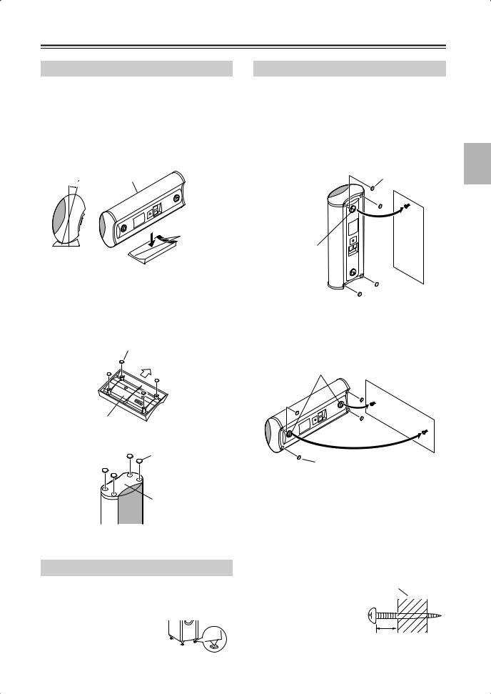
Wall Mounting
The speakers can easily be wall mounted by using the keyhole slots. To prevent the speaker from vibrating against the wall, attach four of the supplied spacers to the keyhole fins on the rear of each speaker.
■ Mounting vertically
To mount the front speakers vertically, use the keyhole slot shown to hang each speaker on a screw that’s securely screwed into the wall.
Rubber spacers
Keyhole slot for vertical wall mounting
■ Mounting horizontally
To mount the center speaker horizontally, use the two keyhole slots shown to hang each speaker on two screws that are securely screwed into the wall.
Keyhole slots for horizontal wall mounting
Rubber spacers
Caution:
A mounting screw’s ability to support a speaker depends on how well it’s anchored to the wall. If you have hollow walls, screw each mounting screw into a stud. If there are no studs, or the walls are solid, use suitable wall anchors.
Use screws with a head diameter of 3/8" or less and a shank diameter of 1/8" or less. With hollow walls, use a cable/pipe detector to check for any power cables or water pipes before making any holes.
Leave a gap of between 1/4" and 5/16" between the wall and the base of the screw head, as shown.
(We recommend that you consult a home installation professional.)
Wall
1/4" – 5/16"
23
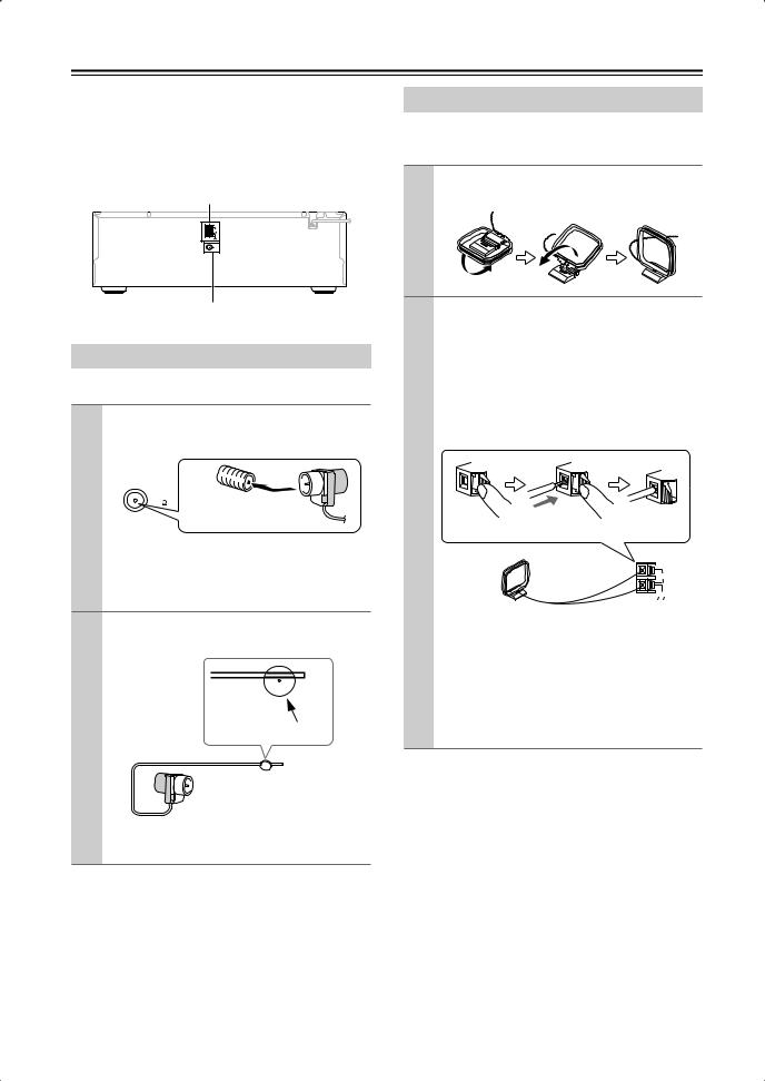
Connecting Antennas
This section explains how to connect the supplied indoor FM antenna and AM loop antenna, and how to connect commercially available outdoor FM and AM antennas.
The AV receiver won’t pick up any radio signals without any antenna connected, so you must connect the antenna to use the tuner.
AM antenna push terminals
AM |
ANTENNA |
FM |
75 |
Connecting the AM Loop Antenna
The supplied indoor AM loop antenna is for indoor use only.
1 Assemble the AM loop antenna, inserting the tabs into the base, as shown.
FM antenna jack
Connecting the Indoor FM Antenna
The supplied indoor FM antenna is for indoor use only.
1 Attach the FM antenna, as shown.
■ American Model
|
|
FM |
Insert the plug fully |
|
|
|
|
75 |
|
|
|
|
|
|
into the jack. |
||
|
|
|
|
|
|
Once your AV receiver is ready for use, you’ll need to tune into an FM radio station and adjust the position of the FM antenna to achieve the best possible reception.
2 Use thumbtacks or something similar to fix the FM antenna into position.
Thumbtacks, etc.
Caution: Be careful that you don’t injure yourself when using thumbtacks.
If you cannot achieve good reception with the supplied indoor FM antenna, try a commercially available outdoor FM antenna instead (see page 25).
2 Connect both wires of the AM loop antenna to the AM push terminals, as shown.
(The antenna’s wires are not polarity sensitive, so they can be connected either way around).
Make sure that the wires are attached securely and that the push terminals are gripping the bare wires, not the insulation.
Push |
Insert wire |
Release |
|
|
AM |
|
|
ANTENNA |
Once your AV receiver is ready for use, you’ll need to tune into an AM radio station and adjust the position of the AM antenna to achieve the best possible reception.
Keep the antenna as far away as possible from your AV receiver, TV, speaker cables, and power cords.
If you cannot achieve good reception with the supplied indoor AM loop antenna, try using it with a commercially available outdoor AM antenna (see page 25).
24
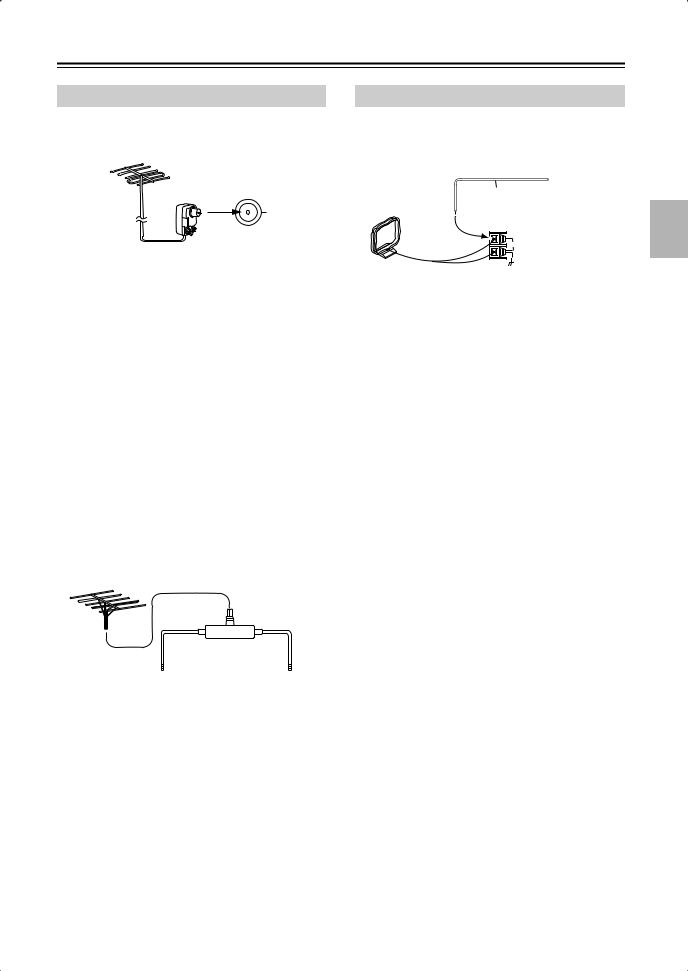
Connecting Antennas—Continued
Connecting an Outdoor FM Antenna
If you cannot achieve good reception with the supplied indoor FM antenna, try a commercially available outdoor FM antenna instead.
FM 75
Notes:
•Outdoor FM antennas work best outside, but usable results can sometimes be obtained when installed in an attic or loft.
•For best results, install the outdoor FM antenna well away from tall buildings, preferably with a clear line of sight to your local FM transmitter.
•Outdoor antenna should be located away from possible noise sources, such as neon signs, busy roads, etc.
•For safety reasons, outdoor antenna should be situated well away from power lines and other high-voltage equipment.
•Outdoor antenna must be grounded in accordance with local regulations to prevent electrical shock hazards.
■ Using a TV/FM Antenna Splitter
It’s best not to use the same antenna for both FM and TV reception, as this can cause interference problems. If circumstances demand it, use a TV/FM antenna splitter, as shown.
TV/FM antenna splitter
To AV receiver |
To TV (or VCR) |
Connecting an Outdoor AM Antenna
If good reception cannot be achieved using the supplied AM loop antenna, an outdoor AM antenna can be used in addition to the loop antenna, as shown.
Outdoor antenna
Insulated antenna cable
AM loop antenna
AM
ANTENNA
Outdoor AM antennas work best when installed horizontally outside, but good results can sometimes be obtained indoors by mounting horizontally above a window. Note that the AM loop antenna should be left connected.
Outdoor antenna must be grounded in accordance with local regulations to prevent electrical shock hazards.
25
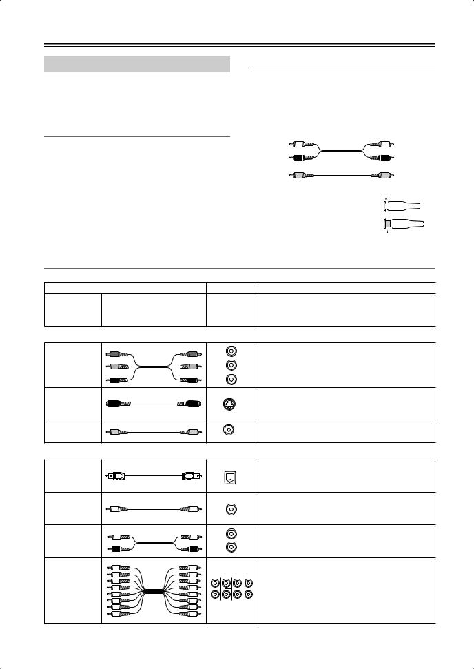
Connecting Your Components
About AV Connections
•Before making any AV connections, read the manuals supplied with your other AV components.
•Don’t connect the power cord until you’ve completed and double-checked all AV connections.
Optical Digital Jacks
The AV receiver’s optical digital jacks have shutter-type covers that open when an optical plug is inserted and close when it’s removed. Push plugs in all the way.
Caution: To prevent shutter damage, hold the optical plug straight when inserting and removing.
AV Connection Color Coding
RCA-type AV connections are usually color coded: red, white, and yellow. Use red plugs to connect rightchannel audio inputs and outputs (typically labeled “R”). Use white plugs to connect left-channel audio inputs and outputs (typically labeled “L”). And use yellow plugs to connect composite video inputs and outputs.
Left (white) |
Analog audio |
Left (white) |
|
||
Right (red) |
|
Right (red) |
(Yellow) |
Composite video |
(Yellow) |
|
• Push plugs in all the way to make |
|
|
|
|
|
|
Right! |
||||||||||
good connections (loose connections |
|
|
|
|
|
|
|
|
|
|
|
|
|
|
|
|
|
can cause noise or malfunctions). |
|
|
|
|
|
|
|
|
|
|
|
|
|
|
|
|
|
• To prevent interference, keep audio |
|
|
|
|
|
|
|
|
|
|
|
|
|
|
|
|
|
and video cables away from power |
|
|
|
|
|
|
Wrong! |
||||||||||
|
|
|
|
|
|
||||||||||||
|
|
|
|
|
|
||||||||||||
cords and speaker cables. |
|
|
|
|
|
|
|
|
|
|
|
|
|
|
|
|
|
AV Cables and Jacks
Audio/Video
Cable |
Jack |
Description |
HDMI connections can carry uncompressed stan-
HDMI
HDMI 


 dardor high-definition digital video and audio and offer the best picture and sound quality.
Video
|
Y |
Y |
Y |
Component video separates the luminance (Y) and |
Component |
PB |
PB |
CB/PB |
color difference signals (PR, PB), providing the best |
video cable |
|
|
picture quality. (Some TV manufacturers label their |
|
PR |
PR |
|
||
|
|
component video jacks slightly differently.) |
||
|
|
|
CR/PR |
|
|
|
|
|
S-Video separates the luminance and color signals |
S-Video cable |
|
|
S |
and provides better picture quality than composite |
|
|
|
|
video. |
Composite |
|
|
V |
Composite video is commonly used on TVs, VCRs, |
video cable |
|
|
|
and other video equipment. |
Audio
Optical digital audio cable
Coaxial digital audio cable
Analog audio cable (RCA)
Multichannel analog audio cable (RCA)
This offers the best sound quality and allows you to
OPTICAL
enjoy Dolby Digital and DTS. The audio quality is the same as for coaxial.
This offers the best sound quality and allows you to
COAXIAL
enjoy Dolby Digital and DTS. The audio quality is the same as for optical.
L |
|
This cable carries analog audio. It’s the most |
R |
|
common connection format for analog audio and |
|
can be found on virtually all AV components. |
|
|
|
|
|
|
This cable carries multichannel analog audio and is |
FRONT CENTER |
SURR SURR BACK typically used to connect DVD players with a 7.1- |
|
|
|
channel analog audio output. Several standard |
|
|
analog audio cables can be used instead of a multi- |
SUBWOOFER |
MULTI CH |
channel cable. |
|
|
|
Note: The AV receiver does not support SCART connections.
26
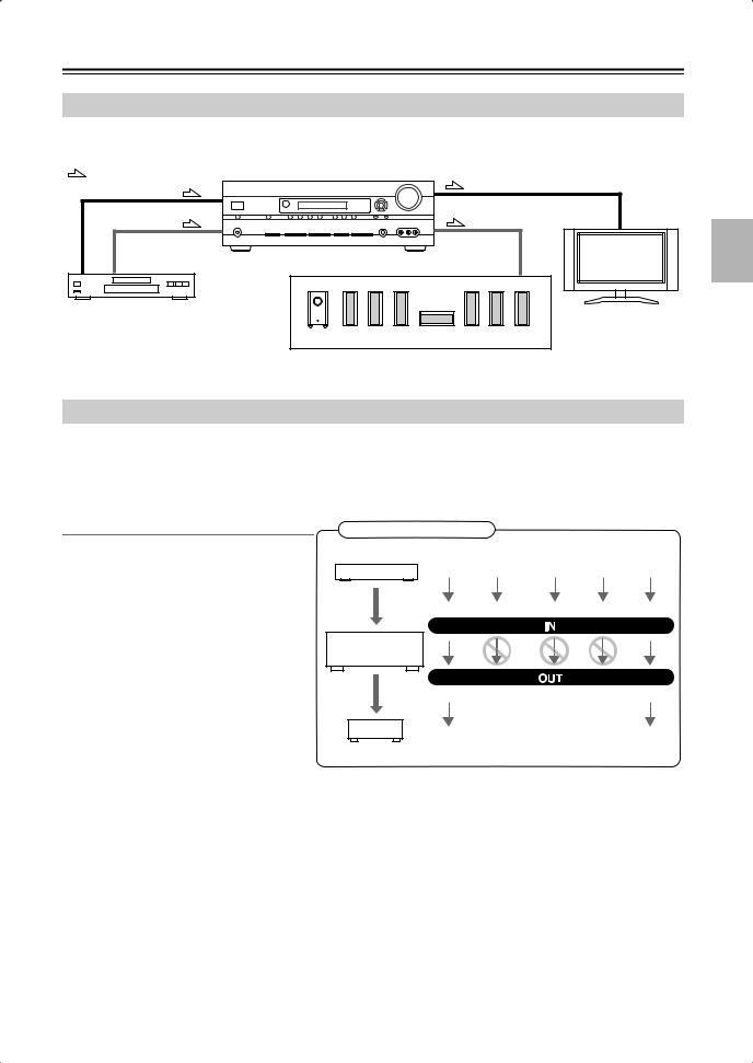
Connecting Your Components—Continued
Connecting Audio and Video Signals to the AV Receiver
By connecting both the audio and video outputs of your DVD player and other AV components to the AV receiver, you can switch the audio and video signals simultaneously simply by changing the input source on the AV receiver.
: Signal Flow |
|
Video |
Video |
|
|
Audio |
Audio |
|
TV, projector, |
|
etc. |
DVD player, etc. |
|
|
Speakers (see page 22 for hookup details) |
Which Connections Should I Use?
The AV receiver supports several connection formats for compatibility with a wide range of AV equipment. The format you choose will depend on the formats supported by your other components. Use the following sections as a guide.
For video components, you must make an audio connection and a video connection.
Audio Connection Formats
Audio equipment can be connected to the AV receiver by using any of the following audio connection formats: analog, optical, coaxial, analog multichannel, or HDMI.
When you connect audio equipment to an HDMI, OPTICAL, or COAXIAL input, you must assign that input to an input selector (see page 47).
When choosing a connection format, bear in mind that the AV receiver does not convert digital input signals for analog line outputs and vice versa. For example, audio signals connected to an optical or coaxial digital input are not output by the analog TAPE OUT.
Audio Signal Flow Chart
DVD player, etc.
HDMI Multichannel Optical Coaxial Analog
AV receiver
HDMI |
Analog |
MD recorder, etc.
If signals are present at more than one input, the inputs will be selected automatically in the following order of priority: HDMI, digital, analog (including multichannel). You can specify which audio inputs the AV receiver checks for the presence of a signal in the “Automatic Audio Input Selection Setup” on page 49.
27
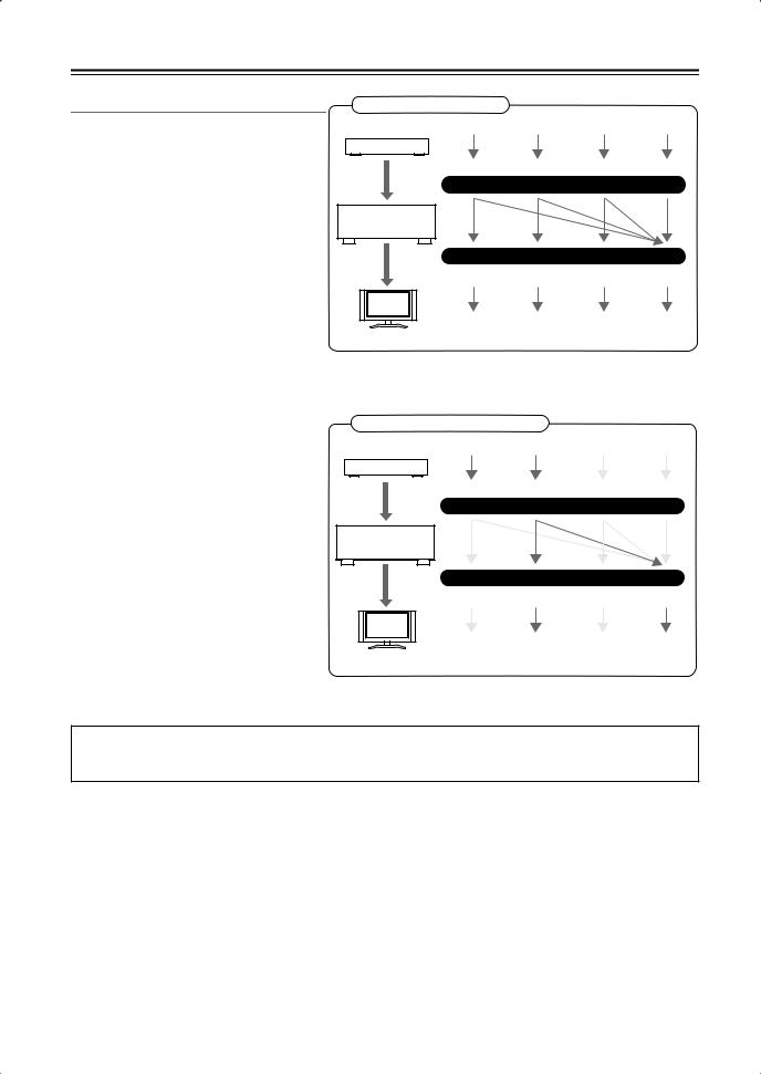
Connecting Your Components—Continued
Video Connection Formats
Video equipment can be connected to the AV receiver by using any one of the following video connection formats: composite video, S-Video, component video, or HDMI, the latter offering the best picture quality.
Video input signals flow through the AV receiver as shown, with composite video, S- Video, and component video sources all being upconverted for the HDMI output.
The composite video, S-Video, and component video outputs pass through their respective input signals as they are.
When you connect audio equipment to an HDMI or COMPONENT input, you must assign that input to an input selector (see pages 46 and 47).
If signals are present at more than one input, the inputs will be selected automatically in the following order of priority: HDMI, component video, S-Video, composite video. However, for component video only, regardless of whether a component video signal is actually present, if a component video input is assigned to the input selector, that component video input will be selected. And if no component video input is assigned to the input selector, this will be interpreted as no component video signal being present.
In the Signal Selection Example shown on the right, video signals are present at both the S-Video and composite video inputs, however, the S-Video signal is automatically selected as the source and video is output by the S-Video and HDMI outputs.
Video Signal Flow Chart
DVD player, etc.
Composite |
S-Video |
Component |
HDMI |
IN
AV receiver
MONITOR OUT
Composite |
S-Video |
Component |
HDMI |
TV, projector, etc.
Signal Selection Example
DVD player, etc.
Composite |
S-Video |
Component |
HDMI |
IN
AV receiver
MONITOR OUT
Composite |
S-Video |
Component |
HDMI |
TV, projector, etc.
The onscreen setup menus appear only on a TV that is connected to the HDMI OUT. If your TV is connected to the composite video or S-Video MONITOR OUT, or the COMPONENT VIDEO OUT, use the HT-R667’s own display when changing settings.
28
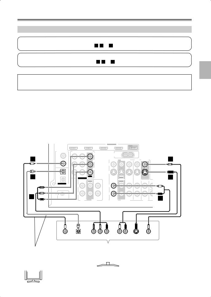
Connecting Your Components—Continued
Connecting a TV or Projector
Step 1: Video Connection
Choose a video connection that matches your TV ( A , B , or C ), and then make the connection.
Step 2: Audio Connection
Choose an audio connection that matches your TV ( a , b , or c ), and then make the connection.
The onscreen setup menus appear only on a TV that is connected to the HDMI OUT. If your TV is connected to the composite video or S-Video MONITOR OUT, or the COMPONENT VIDEO OUT, use the HT-R667’s own display when changing settings.
• To enjoy Dolby Digital and DTS, use connection  or
or  .
.
Connection |
AV receiver |
Signal flow |
TV |
Picture quality |
||
|
A |
|
COMPONENT VIDEO OUT |
|
Component video input |
Best |
|
|
|
MONITOR OUT S |
|
S-Video input |
Better |
|
B |
|||||
|
|
|
|
|
|
|
|
C |
|
MONITOR OUT V |
|
Composite video input |
Standard |
|
|
|
CBL/SAT IN L/R |
|
Analog audio L/R output |
|
|
a |
|
||||
|
|
|
|
|
|
|
|
b |
|
DIGITAL IN COAXIAL 2 |
|
Digital coaxial output |
|
|
|
|
DIGITAL IN OPTICAL 1 |
|
Digital optical output |
|
|
c |
|
||||
|
|
|
|
|
|
|
b
c
A
|
|
ASSIGNABLE |
|
|
|
IN 4 |
IN 3 (CBL/SAT) |
IN 2 (VCR/DVR) |
IN 1 (DVD) |
OUT |
SURR BACK SPEAKERS |
|
|
|
|
|
Bi-AMP for FRONT SPEAKERS |
DIGITAL IN |
COMPONENT VIDEO |
|
|
|
L |
|
|
|
|
||
|
|
|
|
Y |
1 |
|
|
|
|
(DVD) |
|
|
|
|
COAXIAL |
|
|
|
CB/PB |
|
|
|
|
|
2 |
|
|
|
|
(CBL/SAT) |
|
|
|
|
|
|
|
|
CR/PR |
1 |
|
|
|
|
(VCR/DVR) |
|
|
|
|
OPTICAL |
IN 2 (CBL/SAT) |
IN 1(DVD) |
OUT |
|
|
|
|||
2 |
ASSIGNABLE |
|
|
|
|
|
|
|
|
(CD) |
|
IN |
OUT |
IN |
|
|
|||
ASSIGNABLE |
|
|
|
|
|
L |
|
|
|
|
R |
|
|
|
REMOTE |
|
|
|
|
CONTROL |
|
|
|
|
|
|
CD |
|
TAPE |
DOCK |
|
|
|
AM |
(for DS-A1L) |
|
|
|
|
CBL/SAT |
VCR/DVR |
DVD |
MONITOR |
C |
OUT |
V |
V |
R |
|
ANTENNA |
|||
|
|
|
|
|
|
FM |
S |
|
|
|
75 |
|
|
|
S |
|
IN |
OUT |
IN |
IN |
B |
IN |
|
IN |
FRONT |
SURR |
CENTER SURR BACK |
ZONE 2 |
PRE O |
|
OUT |
LINE OUT |
|||||||
|
||||||||
|
|
|
|
|
|
|
SUB |
|
L |
|
|
|
|
L |
L |
WOOF |
|
R |
|
|
|
|
R |
R |
|
SUB a
WOOFER
CBL/SAT |
VCR/DVR |
DVD |
|
|
|
|
L |
|
R |
|
COAXIAL |
OPTICAL |
Y |
PB |
PR |
AUDIO |
S VIDEO |
VIDEO |
OUT |
OUT |
COMPONENT VIDEO IN |
OUT |
IN |
IN |
||
Connect one or the other |
|
|
|
|
|
||
|
|
TV, projector, |
|
|
|||
Connection |
|
must be assigned |
|
|
|
|
|
c |
|
|
|
|
|||
|
|
etc. |
|
|
|||
(see page 47) |
|
|
|
|
|
||
|
|
|
|
|
|
||
|
|
|
|
|
|
|
|
|
|
|
|
|
|
|
|
 If your TV has no audio outputs, connect an audio output from your VCR or cable or satellite Hint! receiver to the AV receiver and use its tuner to listen to TV programs through the AV receiver (see
pages 32 and 34).
29
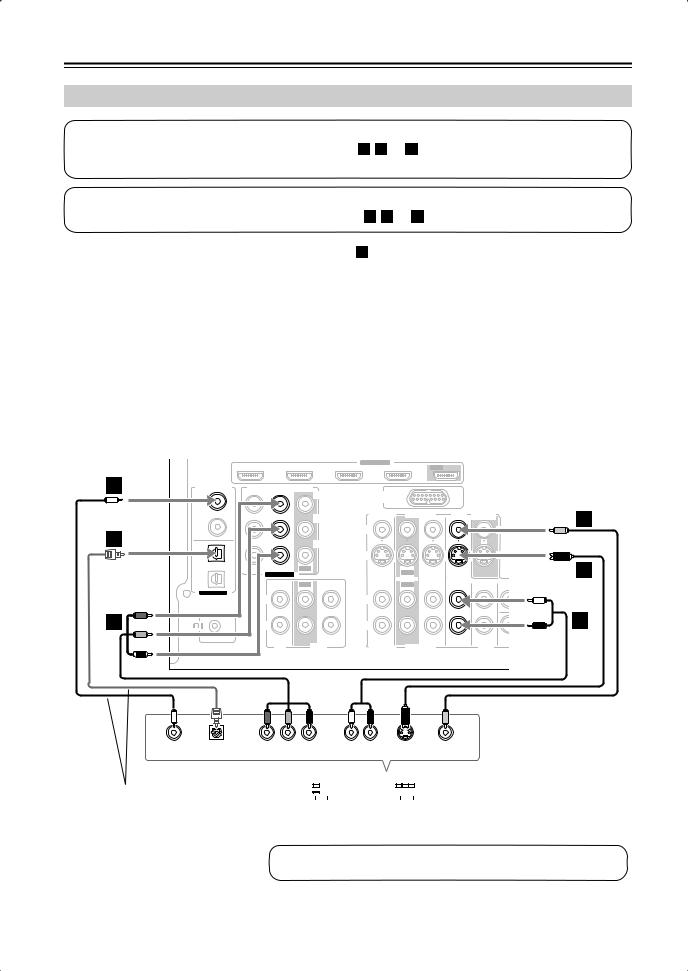
Connecting Your Components—Continued
Connecting a DVD player
Step 1: Video Connection
Choose a video connection that matches your DVD player ( A , B , or C ), and then make the connection.
You must connect the AV receiver to your TV with the same type of connection.
Step 2: Audio Connection
Choose an audio connection that matches your DVD player ( a , b , or c ), and then make the connection.
•To enjoy Dolby Digital and DTS, use connection  or c .
•If your DVD player has main left and right outputs and multichannel left and right outputs, be sure to use the main left and right outputs for connection  .
.
Connection |
AV receiver |
Signal flow |
DVD player |
Picture quality |
||
|
A |
|
COMPONENT VIDEO IN 1 |
|
Component video output |
Best |
|
|
|
DVD IN S |
|
S-Video output |
Better |
|
B |
|||||
|
|
|
|
|
|
|
|
C |
|
DVD IN V |
|
Composite video output |
Standard |
|
|
|
DVD IN FRONT L/R |
|
Analog audio L/R output |
|
|
a |
|
||||
|
|
|
|
|
|
|
|
b |
|
DIGITAL IN COAXIAL 1 |
|
Digital coaxial output |
|
|
|
|
DIGITAL IN OPTICAL 1 |
|
Digital optical output |
|
|
c |
|
||||
|
|
|
|
|
|
|
b
c
A
|
|
ASSIGNABLE |
|
|
|
IN 4 |
IN 3 (CBL/SAT) |
IN 2 (VCR/DVR) |
IN 1 (DVD) |
OUT |
SURR BACK SPEAKERS |
|
|
|
|
|
Bi-AMP for FRONT SPEAKERS |
DIGITAL IN |
COMPONENT VIDEO |
|
|
|
L |
|
|
|
|
||
|
|
|
|
Y |
DOCK |
|
|
|
|
|
AM |
|
|
1 |
|
|
|
|
(for DS-A1L) |
|
|
|
|
|
|
|
|
(DVD) |
|
|
|
|
|
|
|
|
|
|
|
|
|
COAXIAL |
|
|
|
|
CBL/SAT |
VCR/DVR |
DVD |
MONITOR |
|
|
C |
|
|
|
|
|
CB/PB |
OUT |
|
|
|
||||||
|
|
|
|
|
|
|
|
|
|
|
|
||
2 |
|
|
|
|
V |
|
|
|
|
V |
|
R |
|
(CBL/SAT) |
|
|
|
|
|
|
|
|
ANTENNA |
|
|
||
|
|
|
|
|
|
|
|
|
|
|
|
|
|
|
|
|
|
CR/PR |
|
|
|
|
|
|
FM |
|
|
1 |
|
|
|
|
S |
|
|
|
|
S |
75 |
|
|
(VCR/DVR) |
|
|
|
|
|
|
|
|
|
|
|
||
OPTICAL |
IN 2 (CBL/SAT) |
IN 1(DVD) |
OUT |
|
|
|
|
|
|
|
|
B |
|
|
|
IN |
OUT |
IN |
IN |
|
|
|
|
||||
2 |
ASSIGNABLE |
|
|
|
|
|
|
||||||
|
|
|
|
|
|
|
|
|
|
|
ZONE 2 |
PRE OU |
|
(CD) |
|
IN |
OUT |
IN |
IN |
OUT |
IN |
FRONT |
SURR |
CENTER |
SURR BACK |
LINE OUT |
|
|
|
|
|||||||||||
ASSIGNABLE |
|
|
|
|
|
|
|
|
|
|
|
|
SUB |
|
L |
|
|
|
L |
|
|
|
|
|
L |
L |
WOOFE |
|
R |
|
|
|
R |
|
|
|
|
|
R |
a R |
|
REMOTE |
|
|
|
|
|
|
|
|
|
SUB |
|
|
|
CONTROL |
|
|
|
|
|
|
|
|
|
|
|
|
|
|
|
CD |
|
TAPE |
CBL/SAT |
VCR/DVR |
|
DVD |
WOOFER |
|
|
|
|
|
|
|
|
|
|
|
|
||||||
|
|
|
|
L |
|
R |
|
COAXIAL |
OPTICAL |
Y |
PB |
PR |
AUDIO |
S VIDEO |
VIDEO |
OUT |
OUT |
COMPONENT VIDEO OUT |
OUT |
OUT |
OUT |
||
Connect one or the other |
|
|
|
|
|
|
|
|
|
|
|
||
|
|
|
|
|
|
|
|
|
|
|
|||
|
|
|
|
|
|
|
|
|
|
|
|||
|
|
|
|
|
|
|
|
|
|
|
|||
Connection |
|
must be |
|
|
|
|
|
||||||
c |
|
|
DVD player |
||||||||||
assigned (see page 47) |
|
|
|
|
|
|
|
|
|
|
|
||
To connect a DVD player or DVD-Audio/SACD-capable player with a multichannel analog audio output, see page 31.
30
Loading...