


 Loading...
CNC SYSTEM
OSP-E100M
OSP-E10M
OPERATION MANUAL
(6th Edition)
Pub No. 4290-E-R4 (ME32-083-R6) Aug. 2002

4290-E P-(i)
SAFETY PRECAUTIONS
SAFETY PRECAUTIONS
The machine is equipped with safety devices which serve to protect personnel and the machine itself from hazards arising from unforeseen accidents. However, operators must not rely exclusively on these safety devices: they must also become fully familiar with the safety guidelines presented below to ensure accident-free operation.
This instruction manual and the warning signs attached to the machine cover only those hazards which Okuma can predict. Be aware that they do not cover all possible hazards.
1.Precautions Relating to Machine Installation
(1)Install the machine at a site where the following conditions (the conditions for achievement of the guaranteed accuracy) apply.
•Ambient temperature:17 to 25°C
•Ambient humidity:40% to 75% at 20°C (no condensation)
•Site not subject to direct sunlight or excessive vibration; environment as free of dust, acid, corrosive gases, and salt spray as possible.
(2)Prepare a primary power supply that complies with the following requirements.
•Voltage: 200 V
•Voltage fluctuation: ±10% max.
•Power supply frequency: 50/60 Hz
•Do not draw the primary power supply from a distribution panel that also supplies a major noise source (for example, an electric welder or electric discharge machine) since this could cause malfunction of the CNC unit.
•If possible, connect the machine to a ground not used by any other equipment. If there is no choice but to use a common ground, the other equipment must not generate a large amount of noise (such as an electric welder or electric discharge machine).
(3)Installation Environment
Observe the following points when installing the control enclosure.
•Make sure that the CNC unit will not be subject to direct sunlight.
•Make sure that the control enclosure will not be splashed with chips, water, or oil.
•Make sure that the control enclosure and operation panel are not subject to excessive vibrations or shock.
•The permissible ambient temperature range for the control enclosure is 0 to 40°C.
•The permissible ambient humidity range for the control enclosure is 30 to 95% (no condensation).
•The maximum altitude at which the control enclosure can be used is 1000 m (3281ft.).

4290-E P-(ii)
SAFETY PRECAUTIONS
2.Points to Check before Turning on the Power
(1)Close all the doors of the control enclosure and operation panel to prevent the entry of water, chips, and dust.
(2)Make absolutely sure that there is nobody near the moving parts of the machine, and that there are no obstacles around the machine, before starting machine operation.
(3)When turning on the power, turn on the main power disconnect switch first, then the CONTROL ON switch on the operation panel.
3.Precautions Relating to Operation
(1)After turning on the power, carry out inspection and adjustment in accordance with the daily inspection procedure described in this instruction manual.
(2)Use tools whose dimensions and type are appropriate for the work undertaken and the machine specifications. Do not use badly worn tools since they can cause accidents.
(3)Do not, for any reason, touch the spindle or tool while spindle indexing is in progress since the spindle could rotate: this is dangerous.
(4)Check that the workpiece and tool are properly secured.
(5)Never touch a workpiece or tool while it is rotating: this is extremely dangerous.
(6)Do not remove chips by hand while machining is in progress since this is dangerous. Always stop the machine first, then remove the chips with a brush or broom.
(7)Do not operate the machine with any of the safety devices removed. Do not operate the machine with any of the covers removed unless it is necessary to do so.
(8)Always stop the machine before mounting or removing a tool.
(9)Do not approach or touch any moving part of the machine while it is operating.
(10)Do not touch any switch or button with wet hands. This is extremely dangerous.
(11)Before using any switch or button on the operation panel, check that it is the one intended.
4.Precautions Relating to the ATC
(1)The tool clamps of the magazine, spindle, etc., are designed for reliability, but it is possible that a tool could be released and fall in the event of an unforeseen accident, exposing you to danger: do not touch or approach the ATC mechanism during ATC operation.
(2)Always inspect and change tools in the magazine in the manual magazine interrupt mode.
(3)Remove chips adhering to the magazine at appropriate intervals since they can cause misoperation. Do not use compressed air to remove these chips since it will only push the chips further in.
(4)If the ATC stops during operation for some reason and it has to be inspected without turning the power off, do not touch the ATC since it may start moving suddenly.

4290-E P-(iii)
SAFETY PRECAUTIONS
5.On Finishing Work
(1)On finishing work, clean the vicinity of the machine.
(2)Return the ATC, APC and other equipment to the predetermined retraction position.
(3)Always turn off the power to the machine before leaving it.
(4)To turn off the power, turn off the CONTROL ON switch on the operation panel first, then the main power disconnect switch.
6.Precautions during Maintenance Inspection and When Trouble Occurs
In order to prevent unforeseen accidents, damage to the machine, etc., it is essential to observe the following points when performing maintenance inspections or during checking when trouble has occurred.
(1)When trouble occurs, press the emergency stop button on the operation panel to stop the machine.
(2)Consult the person responsible for maintenance to determine what corrective measures need to be taken.
(3)If two or more persons must work together, establish signals so that they can communicate to confirm safety before proceeding to each new step.
(4)Use only the specified replacement parts and fuses.
(5)Always turn the power off before starting inspection or changing parts.
(6)When parts are removed during inspection or repair work, always replace them as they were and secure them properly with their screws, etc.
(7)When carrying out inspections in which measuring instruments are used - for example voltage checks - make sure the instrument is properly calibrated.
(8)Do not keep combustible materials or metals inside the control enclosure or terminal box.
(9)Check that cables and wires are free of damage: damaged cables and wires will cause current leakage and electric shocks.
(10)Maintenance inside the Control Enclosure
a)Switch the main power disconnect switch OFF before opening the control enclosure door.
b)Even when the main power disconnect switch is OFF, there may some residual charge in the MCS drive unit (servo/spindle), and for this reason only service personnel are permitted to perform any work on this unit. Even then, they must observe the following precautions.
•MCS drive unit (servo/spindle)
The residual voltage discharges two minutes after the main switch is turned OFF.
c)The control enclosure contains the NC unit, and the NC unit has a printed circuit board whose memory stores the machining programs, parameters, etc. In order to ensure that the contents of this memory will be retained even when the power is switched off, the memory is supplied with power by a battery. Depending on how the printed circuit boards are handled, the contents of the memory may be destroyed and for this reason only service personnel should handle these boards.

4290-E P-(iv)
SAFETY PRECAUTIONS
(11)Periodic Inspection of the Control Enclosure
a)Cleaning the cooling unit
The cooling unit in the door of the control enclosure serves to prevent excessive temperature rise inside the control enclosure and increase the reliability of the NC unit. Inspect the following points every three months.
•Is the fan motor inside the cooling unit working?
The motor is normal if there is a strong draft from the unit.
•Is the external air inlet blocked?
If it is blocked, clean it with compressed air.
7.General Precautions
(1)Keep the vicinity of the machine clean and tidy.
(2)Wear appropriate clothing while working, and follow the instructions of someone with sufficient training.
(3)Make sure that your clothes and hair cannot become entangled in the machine. Machine operators must wear safety equipment such as safety shoes and goggles.
(4)Machine operators must read the instruction manual carefully and make sure of the correct procedure before operating the machine.
(5)Memorize the position of the emergency stop button so that you can press it immediately at any time and from any position.
(6)Do not access the inside of the control panel, transformer, motor, etc., since they contain highvoltage terminals and other components which are extremely dangerous.
(7)If two or more persons must work together, establish signals so that they can communicate to confirm safety before proceeding to each new step.
8.Symbols Used in This Manual
The following warning indications are used in this manual to draw attention to information of particular importance. Read the instructions marked with these symbols carefully and follow them.

 DANGER

 WARNING

 CAUTION
NOTICE
Indicates an imminent hazard which, if not avoided, will result in death or serious injury.
Indicates hazards which, if not avoided, could result in death or serious injury.
Indicates hazards which, if not avoided, could result in minor injuries or damage to devices or equipment.
Indicates precautions relating to operation or use.

4290-E P-(i)
INTRODUCTION
INTRODUCTION
Thank you very much for choosing our CNC system. This numerical control system is a expandable CNC with various features including a multi-main CPU system. Major features of the CNC system are described below.
(1)Expandable CNC with a multi-main CPU system
A multi-main CPU system on which up to seven engines (main CPUs) can be mounted is used. An excellent performance and cost effectiveness have been realized as a leader of increasingly rapid and accurate machine tools. The CNC system can be adapted to any models and variations by changing the construction of the main CPUs. The machine is controlled by a built-in PLC.
(2)Compact and highly reliable
The CNC system has become compact and highly reliable because of advanced hardware technology, including UCMB (Universal Compact Main Board), I/O link, and servo link. The 'variable software' as a technical philosophy of the OSPs supported by a flash memory. Functions may be added to the CNC system as required after delivery.
(3)NC operation panels
The following types of NC operation panels are offered to improve the user-friendliness.
•Color CRT operation panels
•Thin color operation panels (horizontal)
•Thin color operation panels (vertical)
One or more of the above types may not be used for some models.
(4)Machining management functions
These functions contribute to the efficient operation of the CNC system and improve the profitability from small quantity production of multiple items and variable quantity production of variations. Major control functions are described below.
a) Reduction of setup time
With increase in small-volume production, machining data setting is more frequently needed. The simplified file operation facilitates such troublesome operation. The documents necessary for setup, such as work instructions, are displayed on the CNC system to eliminate the necessity of controlling drawings and further reduce the setup time.
b) Production Status Monitor
The progress and operation status can be checked on a real-time basis on the screen of the CNC system.
c) Reduction of troubleshooting time
Correct information is quickly available for troubleshooting.
(5)Help functions
When an alarm is raised, press the help key to view the content of the alarm. This helps take quick action against the alarm.
To operate the CNC system to its maximum performance, thoroughly read and understand this instruction manual before use.
Keep this instruction manual at hand so that it will be available when you need a help.
Screens
Different screens are used for different models. Therefore, the screens used on your CNC system may differ from those shown in this manual.

4290-E P-(i)
CONSTRUCTION OF THIS MANUAL
CONSTRUCTION OF THIS MANUAL
This instruction manual consists of five chapters.
FUNDAMENTALS
This chapter describes the specifications, part names, and functions. Description of the part names and functions includes explanation of switches on the NC operation panels, screen transition, and basic operations on each screen.
OPERATION
This chapter describes how to operate the machine from the NC operation panel for different operation modes (manual, MDI, and automatic). The on-screen operating procedures are described in each operation mode.
DATA OPERATION
This chapter describes file operations, programming operations, parameter and data setting and other data related operations.
Just like the chapter of Operation, descriptions are given by data setting mode (zero setting, tool data setting, parameter setting, and programming).
APPENDIX
Appendix includes view of operation panels, tables of EIA/ISO codes, and lists of G codes, M codes, and system variables.
SPECIAL FUNCTIONS (separate manual)
Some of the functions of the machine and CNC system are described. A description of the concept necessary for functional operations is added for your further understanding.

|
|
4290-E P-(i) |
|
|
TABLE OF CONTENTS |
TABLE OF CONTENTS |
|
|
FUNDAMENTALS |
|
|
SECTION 1 PART NAMES AND FUNCTION.................................................................. |
1 |
|
1. |
Operation Panels .......................................................................................................................... |
1 |
|
1-1. Basic Construction of Operation Panels................................................................................ |
1 |
|
1-2. Guide to Controls on Operation Panels................................................................................. |
2 |
2. |
SCREENS .................................................................................................................................. |
12 |
|
2-1. Mode Transition Charts ....................................................................................................... |
12 |
|
2-2. Screen Operations............................................................................................................... |
22 |
3. |
One-touch Window Close Operation .......................................................................................... |
25 |
OPERATION |
|
|
SECTION 1 TURNING THE POWER ON AND OFF..................................................... |
26 |
|
1. |
Turning the Power ON ................................................................................................................ |
26 |
2. |
Turning the Power OFF .............................................................................................................. |
26 |
3. |
Emergency Stop ......................................................................................................................... |
26 |
SECTION 2 OPERATION MODES................................................................................ |
27 |
|
1. |
Operation Mode Basic Screen.................................................................................................... |
27 |
|
1-1. Screen Display .................................................................................................................... |
27 |
|
1-2. Pop-up Windows ................................................................................................................. |
28 |
SECTION 3 MANUAL OPERATION .............................................................................. |
30 |
|
1. |
Axis Feed Operations ................................................................................................................. |
30 |
|
1-1. Manual Rapid Traverse Operation ...................................................................................... |
30 |
|
1-2. Manual Cutting Feed Operation .......................................................................................... |
31 |
|
1-3. Pulse Handle Feed .............................................................................................................. |
32 |
2. |
Spindle Operation ....................................................................................................................... |
33 |
|
2-1. Starting the Spindle ............................................................................................................. |
33 |
|
2-2. Stopping the Spindle ........................................................................................................... |
33 |
|
2-3. Releasing the Spindle.......................................................................................................... |
33 |
|
2-4. Spindle Orientation .............................................................................................................. |
33 |
3. |
Indexing the Swivel Head and the Attachment ........................................................................... |
34 |
4. |
ATC............................................................................................................................................. |
35 |
|
4-1. ATC Operation..................................................................................................................... |
35 |
|
4-2. Manual Tool Change Operation .......................................................................................... |
43 |

|
|
4290-E P-(ii) |
|
|
TABLE OF CONTENTS |
|
4-3. Manual Magazine Operation ............................................................................................... |
45 |
|
4-4. Manual Tool Change during Automatic Operation .............................................................. |
46 |
5. |
APC ............................................................................................................................................ |
47 |
|
5-1. APC Operation .................................................................................................................... |
47 |
|
5-2. Automatic APC Operations.................................................................................................. |
49 |
|
5-3. Manual APC Operation........................................................................................................ |
50 |
6. |
Others ......................................................................................................................................... |
51 |
SECTION 4 MDI OPERATION ...................................................................................... |
52 |
|
1. |
Procedure for MDI Operation...................................................................................................... |
52 |
2. |
Automatic Operation and MDI Operation.................................................................................... |
53 |
3. |
Subprogram Call in MDI Operation............................................................................................. |
54 |
SECTION 5 AUTOMATIC OPERATION........................................................................ |
55 |
|
1. |
Program Files ............................................................................................................................. |
55 |
2. |
Program Selection ...................................................................................................................... |
57 |
|
2-1. Selection of Main/Subprogram ............................................................................................ |
57 |
|
2-2. Schedule Program Function ................................................................................................ |
60 |
3. |
Cycle Start and Slide Hold.......................................................................................................... |
62 |
|
3-1. Cycle Start ........................................................................................................................... |
62 |
|
3-2. Slide Hold ............................................................................................................................ |
63 |
4. |
Resetting the NC ........................................................................................................................ |
65 |
5. |
Sequence Number Search and Mid-Cycle Start......................................................................... |
66 |
|
5-1. Sequence Number Search .................................................................................................. |
66 |
|
5-2. Mid-Cycle Start (Start after Sequence Number Search) ..................................................... |
69 |
6. |
Return Search and Sequence Restart ....................................................................................... |
70 |
|
6-1. Return Search ..................................................................................................................... |
70 |
|
6-2. Sequence Restart................................................................................................................ |
73 |
7. |
Sequence Stop (Option) ............................................................................................................. |
74 |
8. |
Single Block ................................................................................................................................ |
76 |
9. |
Optional Block Skip..................................................................................................................... |
77 |
10.Program Branch.......................................................................................................................... |
77 |
|
11.Optional Stop .............................................................................................................................. |
77 |
|
12.Mirror Image Function................................................................................................................. |
78 |
|
|
12-1.Mirror Image (Local Coordinate System)............................................................................ |
78 |
|
12-2.Mirror Image Function in Work Coordinate System............................................................ |
81 |
13.Override ...................................................................................................................................... |
84 |
|
|
13-1.Feedrate Override .............................................................................................................. |
84 |
|
13-2.Spindle Override ................................................................................................................ |
84 |
14.Manual Intervention and Restart................................................................................................. |
85 |
|

|
|
4290-E P-(iii) |
|
|
TABLE OF CONTENTS |
15.Pulse Handle Shift Operation ..................................................................................................... |
88 |
|
16.Lock Functions............................................................................................................................ |
89 |
|
|
16-1.Machine Lock ..................................................................................................................... |
89 |
|
16-2.Axis Command Cancel ....................................................................................................... |
89 |
|
16-3.Auxiliary (S.T.M) Function Lock.......................................................................................... |
89 |
17.Dry Run....................................................................................................................................... |
90 |
|
18.Library Program Registration...................................................................................................... |
91 |
|
|
18-1.Registering a library program ............................................................................................. |
92 |
|
18-2.Erasing a library program ................................................................................................... |
93 |
|
18-3.Initializing library program storage buffer area ................................................................... |
93 |
|
18-4.Specifying the library program storage buffer area size ..................................................... |
93 |
19.Editing Selected Program ........................................................................................................... |
94 |
|
|
19-1.Quick Edit Function ............................................................................................................ |
94 |
|
19-2.Editing the Main Program ................................................................................................... |
96 |
20.Operation End Lamp (Option)..................................................................................................... |
97 |
|
21.Operation End Buzzer (Option) .................................................................................................. |
97 |
|
22.Alarm Lamp (Option) .................................................................................................................. |
97 |
|
23.Automatic Power OFF (Option) .................................................................................................. |
97 |
|
24.Work Counter (Option)................................................................................................................ |
98 |
|
25.Hour Meter (Option).................................................................................................................... |
99 |
|
|
25-1.POWER ON TIME Hour Meter .......................................................................................... |
99 |
|
25-2.NC RUNNING TIME Hour Meter ....................................................................................... |
99 |
|
25-3.CUTTING TIME Hour Meter ............................................................................................... |
99 |
|
25-4.SPINDLE REVOLUTION TIME Hour Meter ...................................................................... |
99 |
SECTION 6 NC OPERATION PANEL/SCREEN DISPLAY......................................... |
100 |
|
1. |
Actual Position Display ............................................................................................................. |
100 |
|
1-1. ACTUAL POSITION display screen 1/4 (normal display screen)...................................... |
100 |
|
1-2. ACTUAL POSITION display screen 2/4 |
|
|
(RELATIVE ACTUAL POSITION display screen) ............................................................. |
103 |
|
1-3. ACTUAL POSITION display screen 3/4 (Detail display screen)........................................ |
106 |
|
1-4. ACTUAL POSITION display screen 4/4 ............................................................................ |
107 |
2. |
Main Program Display .............................................................................................................. |
108 |
|
2-1. Main program display screen with machine conditions ..................................................... |
108 |
|
2-2. Main program display screen with subprogram ................................................................. |
109 |
|
2-3. Main program display screen with valid G/M code ............................................................ |
110 |
3. |
Schedule Program Display ....................................................................................................... |
111 |
|
3-1. Schedule program display screen with machine conditions .............................................. |
111 |
|
3-2. Schedule program display screen with main program....................................................... |
112 |
4. |
MDI Program Display................................................................................................................ |
113 |
|
|
4290-E P-(iv) |
|
|
TABLE OF CONTENTS |
5. |
Block Data Display.................................................................................................................... |
114 |
SECTION 7 HELP FUNCTION .................................................................................... |
116 |
|
1. |
Help Screen .............................................................................................................................. |
117 |
|
1-1. Operation with the function menu...................................................................................... |
118 |
|
1-2. Selecting Operation from the CONTENTS Screen............................................................ |
118 |
2. |
The Head CONTENTS Screen of POCKETMANUAL .............................................................. |
119 |
3. |
Search ...................................................................................................................................... |
120 |
4. |
Terminating the HELP Screen .................................................................................................. |
121 |
5. |
Supplement............................................................................................................................... |
121 |
DATA OPERATION |
|
|
SECTION 1 DATA SETTING MODES......................................................................... |
122 |
|
1. |
Guide to Modes ........................................................................................................................ |
122 |
SECTION 2 ZERO SETTING....................................................................................... |
123 |
|
1. |
Work Coordinate System Zero Point ........................................................................................ |
123 |
2. |
Zero Offset Setting.................................................................................................................... |
123 |
|
2-1. Basic Procedure for Setting Zero Offset Data ................................................................... |
123 |
|
2-2. Other Operations ............................................................................................................... |
125 |
SECTION 3 TOOL DATA SETTING ............................................................................ |
126 |
|
1. |
Tool Data Setting Operation ..................................................................................................... |
126 |
|
1-1. Basic Tool Data Setting Operation .................................................................................... |
126 |
|
1-2. Other Operations ............................................................................................................... |
129 |
2. |
Tool Shape ............................................................................................................................... |
130 |
3. |
ATC Pot Number/Tool Number Correspondence ..................................................................... |
133 |
|
3-1. Memory Random ATC....................................................................................................... |
133 |
|
3-2. ATC with Fixed Addresses (Including Multi-magazine) ..................................................... |
137 |
|
3-3. Collective clear (TOOL CANCEL) and collective setting (TOOL SET).............................. |
141 |
SECTION 4 PARAMETER SETTING .......................................................................... |
142 |
|
1. |
Types of Parameter .................................................................................................................. |
142 |
2. |
Basic Parameter Setting Operations ........................................................................................ |
143 |
|
2-1. Parameter Setting Screens ............................................................................................... |
143 |
|
2-2. Setting Parameters............................................................................................................ |
144 |
|
2-3. Other Operations ............................................................................................................... |
146 |
3. |
SETTING THE PARAMETERS ................................................................................................ |
149 |
|
3-1. General Parameters .......................................................................................................... |
149 |

|
|
4290-E P-(v) |
|
|
TABLE OF CONTENTS |
|
3-2. NC Optional Parameters ................................................................................................... |
163 |
|
3-3. Machine User Parameter................................................................................................... |
194 |
|
3-4. Machine System Parameter .............................................................................................. |
223 |
SECTION 5 PARAMETER I/O FUNCTION ................................................................. |
231 |
|
1. |
Parameter Input/Output Operations.......................................................................................... |
231 |
|
1-1. Input................................................................................................................................... |
232 |
|
1-2. Output................................................................................................................................ |
233 |
|
1-3. Verify ................................................................................................................................. |
238 |
|
1-4. Correspondence between Q Numbers and Parameters ................................................... |
241 |
|
1-5. Tape Format ...................................................................................................................... |
244 |
|
1-6. Supplementary Explanation of Parameter Input/Output Function ..................................... |
245 |
SECTION 6 PROGRAM OPERATIONS...................................................................... |
247 |
|
1. |
Basic Screen in the Program Operation Mode ......................................................................... |
247 |
|
1-1. DIRECTORY Screen ......................................................................................................... |
247 |
|
1-2. PROGRAM EDITING Screen ............................................................................................ |
248 |
2. |
Program File Operations........................................................................................................... |
252 |
|
2-1. Changing the Directory Display ......................................................................................... |
252 |
|
2-2. Creating a New File ........................................................................................................... |
257 |
|
2-3. Displaying a Program Source............................................................................................ |
258 |
|
2-4. Copying a File.................................................................................................................... |
259 |
|
2-5. Renaming a File ................................................................................................................ |
261 |
|
2-6. Deleting a File.................................................................................................................... |
262 |
|
2-7. Protecting a File................................................................................................................. |
263 |
|
2-8. File Operations .................................................................................................................. |
264 |
3. |
Program Editing Operations ..................................................................................................... |
277 |
|
3-1. Copy .................................................................................................................................. |
279 |
|
3-2. Delete ................................................................................................................................ |
280 |
|
3-3. Paste ................................................................................................................................. |
281 |
|
3-4. 1 Line Insert....................................................................................................................... |
281 |
|
3-5. 1 Character Delete ............................................................................................................ |
282 |
|
3-6. Overwr/Insert ..................................................................................................................... |
282 |
|
3-7. Another File ....................................................................................................................... |
283 |
|
3-8. Find.................................................................................................................................... |
286 |
|
3-9. Replace ............................................................................................................................. |
288 |
|
3-10.Line Jump ......................................................................................................................... |
290 |
|
3-11.Sequence No. Arrange ..................................................................................................... |
292 |
|
3-12.File Insert.......................................................................................................................... |
294 |
|
3-13.Save ................................................................................................................................. |
296 |

|
|
4290-E P-(vi) |
|
|
TABLE OF CONTENTS |
|
3-14.Quit / Stop......................................................................................................................... |
297 |
|
3-15.Select & Quit..................................................................................................................... |
298 |
|
3-16.Power Failure Measures in Direct Editing Mode .............................................................. |
299 |
4. |
Device Information Operations ................................................................................................. |
300 |
5. |
Initialization ............................................................................................................................... |
301 |
6. |
RS232C .................................................................................................................................... |
303 |
|
6-1. Input/Output Operation ...................................................................................................... |
304 |
|
6-2. Tape Format ...................................................................................................................... |
310 |
|
6-3. Specifications for RS232C Interface.................................................................................. |
312 |
|
6-4. Connection with External Device....................................................................................... |
314 |
7. |
Preference Setting Operations ................................................................................................. |
322 |
|
7-1. Date/Time .......................................................................................................................... |
323 |
|
7-2. File Pattern ........................................................................................................................ |
324 |
|
7-3. File Format ........................................................................................................................ |
325 |
|
7-4. Sort .................................................................................................................................... |
326 |
|
7-5. % Code Operation ............................................................................................................. |
327 |
|
7-6. Edit Mode Property............................................................................................................ |
328 |
|
7-7. Display Property ................................................................................................................ |
329 |
APPENDIX |
|
|
SECTION 1 APPENDED FIGURES ............................................................................ |
330 |
|
1. |
Optional Parameter................................................................................................................... |
330 |

FUNDAMENTALS

4290-E P-1
SECTION 1 PART NAMES AND FUNCTION
SECTION 1 PART NAMES AND FUNCTION
1.Operation Panels
1-1. Basic Construction of Operation Panels
The machine has eight human-machine interfaces with different applications:
(1)NC Operation Panel
Used for operations other than those in the manual mode, such as file operations and data setting.
(2)Machine Operation Panel
Features the switches and keys used mainly for manual operation.
(3)Option Panel
Used with special machine specifications that require additional switches and indicating lamps. The arrangement of the switches and indicating lamps differs depending on the selected optional specification.
(4)Manual Tool Change Panel
Used for changing tools manually.
The arrangement of the switches differs depending on the machine model.
(5)Manual Magazine Operation Panel
Used for operating the magazine manually.
The arrangement of the switches differs depending on the machine model.
(6)APC Operation Panel (for Parallel Type 2-Pallet APC) Used for operating the pallet changer manually.
The arrangement of the switches differs depending on the machine model.
(7)AAC Operation Panel
Used for changing attachments manually.
(8)Manual Attachment Tool Change Panel
Used for changing tools manually for attachment.
4290-E P-2
SECTION 1 PART NAMES AND FUNCTION
1-2. Guide to Controls on Operation Panels
1-2-1. Operation Mode Selection Keys
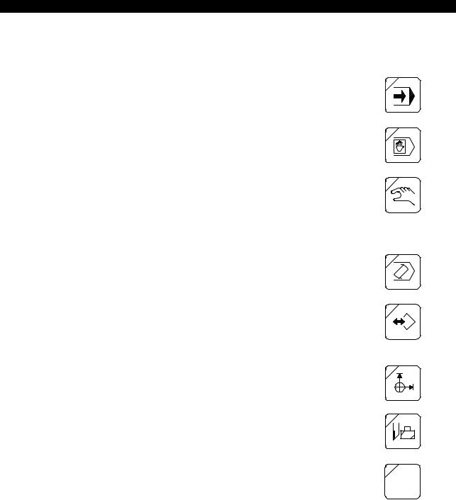
(1)AUTO Key
Pressed to select the automatic operation mode, in which a part program stored in the memory disk (MD) is read to the working memory of the NC and executed.
(2)MDI Key
Pressed to select the MDI operation mode, in which a program is written one block at a time from the keyboard of the NC operation panel and executed in the same way as in automatic operation.
(3)MANUAL Key
Pressed to select the manual operation mode, in which the manual operation switches on the machine operation panel, pulse handle operation box, etc., are used to operate the machine.
1-2-2. Data Setting Mode Selection Keys
(1)EDIT AUX. Key
Pressed to select the program operation mode, in which program files and data files can be edited, punched, printed, displayed, and deleted.
(2)PARAMETER Key
Pressed to select the parameter mode, in which the following parameters are set: system parameter, user parameter, common variables, NC optional parameter, machine system parameter and machine user parameter.
(3)ZERO SET Key
Pressed to select the zero set mode, in which the zero offset data is set.
(4)TOOL DATA Key
Pressed to select the tool data mode, in which the tool length offset data, cutter radius compensation data, ATC tool data, and tool management data can be set, changed, or displayed.
(5)MacMan Key
Pressed to select the MacMan mode, in which the machining management function can be used.
P
MacMan

4290-E P-3
SECTION 1 PART NAMES AND FUNCTION
1-2-3. NC Status Indicating Lamps
S.T.M |
? |
(1)RUN Lamp
This lamp is lit while the machine is actually operating in the automatic or MDI mode.
(2)S.T.M Lamp
This lamp is lit while S (spindle), T (tool), or M (miscellaneous) operation is being executed.
(3)SLIDE HOLD Lamp
This lamp goes on when the [SLIDE HOLD] button is pressed.
(4)PROGRAM STOP Lamp
This lamp is lit during a program stop (M00) or optional stop (M01) in the automatic or MDI mode.
It blinks during dwell (G04).
(5)LIMIT Lamp
This lamp goes on when an axis reaches the variable limit position.
(6)ALARM Lamp
This lamp goes at the occurrence of an alarm.
Note that it does not light when a warning message is displayed due to erroneous operation.
4290-E P-4
SECTION 1 PART NAMES AND FUNCTION
1-2-4. Other Controls on the NC Operation Panel
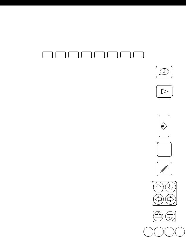
(1)Function Keys: F1 to F8
When the operator selects an operation mode, the functions (operations) available in the selected mode are displayed on the bottom line of the screen. The function keys (F1 to F8) correspond to the displays for individual functions, and the functions are executed by pressing the corresponding function key.
Only those functions that are valid in the current step of an operation and the currently selected mode are displayed.
F1 |
F2 |
F3 |
F4 |
F5 |
F6 |
F7 |
F8 |
(2)Help Key
This key is located to the left of function key [F1].
It is used to display descriptions of alarms which occur during machine operation, and the alarm history.
(3)Extend key
This key is located to the right of function key [F8].
It is functional only when a triangular mark is displayed at the right end of the function menu. It is used when all of the accessible items in a function menu cannot be displayed at one time; pressing the [Extend] key changes the function menu.
(4)WRITE Key
Press this key to select an operation, and to confirm data after inputting it.
(5)BS (Backspace) Key
|
Used when you have made a mistake in inputting data. Pressing this |
|
|
BS |
|
|
key deletes the character input last. |
|
|
|
|
(6) |
CANCEL Key |
|
|
|
|
|
Used when you have made a mistake in inputting data. Pressing this |
|
|
|
|
|
key deletes a line of data that has not been confirmed. |
|
|
|
|
(7) |
Cursor Keys |
|
|
|
|
|
These keys move the screen cursor in the directions indicated on |
|
|
|
|
|
the keys. |
|
|
|
|
(8) |
Page Keys |
|
|
|
|
|
If the information called out is displayed in more than one page, the |
|
P |
P |
|
|
page keys are used to change the display page. |
|
|
||
|
|
|
|
|
|
(9) |
Operator Keys |
|
|
|
|
|
These keys are used when multiple data have to be input with oper- |
/ |
* |
+ |
- |
|
ators during program editing or when setting data. |

4290-E P-5
SECTION 1 PART NAMES AND FUNCTION
(10)Character Keys
Character keys are used to input characters for data input, program operation, and file editing operations.
To input the character shown at the upper right corner of a key top, press the key while holding down the [UPPER CASE] key.
While the [CAPS LOCK] key is pressed (indicating lamp at the upper left corner of the key lit), these input upper case letters of the alphabet (A to Z). When the [CAPS LOCK] key is not pressed, lower case letters (a to z) are input.
! |
to |
; |
|
Z |
|||
A |
|
!
SHIFT + A
(11)Ten Keys
The ten keys are used to input numbers for data input, program operations, and file editing operations.
CAPS
LOCK
7 8 9
4 5 6
1 2 3
0 . =
4290-E P-6
SECTION 1 PART NAMES AND FUNCTION
1-2-5. Controls on the Machine Operation Panel
The flat keys on the machine operation panel have the features indicated below depending on whether or not they have indicating lamps.
< Flat keys with an indicating lamp >
The indicating lamp in a key indicates if the function of the key is valid or not.
•Indicating lamp lit: Key function is valid.
•Indicating lamp unlit: Key function is invalid.
<Flat keys without an indicating lamp >
The function of the key is in effect only while the key is held down. While the key is not being pressed, the function is not in effect.
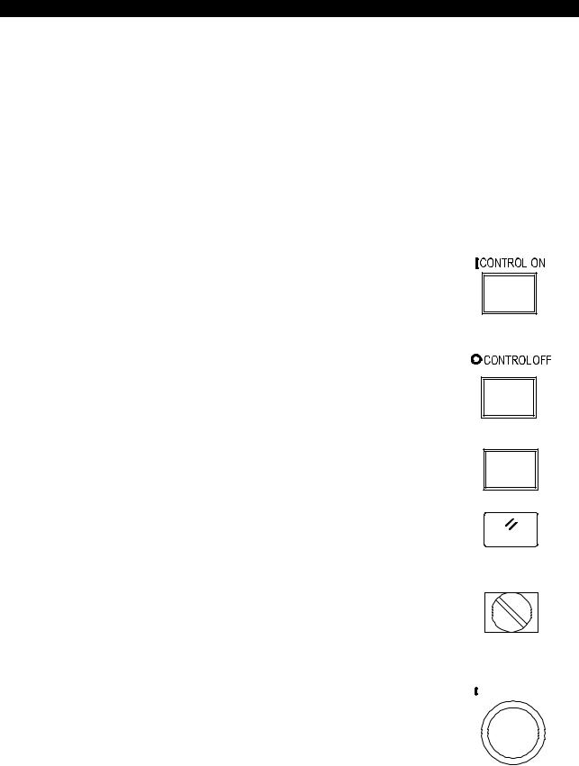
(1)CONTROL ON Switch
It operates only after the main switch of the machine has been turned on.
The pilot lamp in this switch lights when the control power is turned on.
If the [EMERGENCY STOP] button is pressed, the pilot lamp in this switch goes off. To recover from the emergency stop state, press the [CONTROL ON] switch again.
(2)CONTROL OFF Switch
When shutting off the power, turn off the control power first by pressing the [CONTROL OFF] switch before turning off the main switch of the machine.
(3)RESTART Switch
This switch is used, for example, to restart the operation which has been interrupted due to the door interlock function. To restart the suspended operation, press the [RESTART] switch and then the [CYCLE START] button.
(4)RESET Switch
Used to recover normal operation when the machine is in the stopped state due, for example, to an alarm.
(5)NC PANEL Switch
When the UNLOCK position is selected, all operations at the NC and machine operation panels are enabled.
When the EDIT LOCK position is selected, operations in the program operation (EDIT AUX) mode and (PARAMETER) mode are disabled.
When the LOCK position is selected, all operations at the NC operation panel are disabled.
(6)CYCLE START Button
The [CYCLE START] button is used to start machine operation as directed by the commands that have been given.
The CYCLE START signal is output when this button is released after being pressed.
RESTART
RESET
NC PANEL
EDIT
LOCK UNLOCK LOCK
 CYCLE START

4290-E P-7
SECTION 1 PART NAMES AND FUNCTION
(7) SLIDE HOLD Button
Pressing this button stops motion on the X-, Y-, and Z-axis immedi-  SLIDE HOLD ately. To resume axis movements, press the [CYCLE START] but-
ton.
If none of the X-, Y-, and Z-axes is moving when this button is pressed, the slide hold state is established when the current sequence is completed, or when the next axis motion starts.
(8)EMERGENCY STOP Button
This shuts off the power supply to the machine with the NC power kept active.
To release the emergency stop state, unlock the [EMERGENCY STOP] button and press the [CONTROL ON] button.
(9)AXIS SELECT Keys
These keys are used to select the axis to be moved manually (rapid feed, cutting feed).
To move an axis using the pulse handle, select [PULSE HANDLE].
(10)RAPID Keys
These keys are used to move the axis selected by the [AXIS SELECT] key at a rapid traverse rate in the direction indicated in a
key. |
+ |
The selected axis moves at a rapid traverse rate only while the |
|
[RAPID] key is held pressed. |
|
EMG. STOP
RAPID
[Supplement]
Rapid traverse rate differs depending on the machine model and specifications.
(11)JOG Keys
These keys are used to move the axis selected by the [AXIS SELECT] key at a cutting feedrate in the direction indicated in a key.
Once a key is pressed, the axis keeps moving even if it is released. |
+ |
To stop axis feed, press the [STOP] key. |
|
[Supplement]
Cutting feedrate differs depending on the machine model and specifications.
(12)SPINDLE STOP Key
Used to stop the spindle manually.
(13)SPINDLE CW Key
Used to start the spindle in the forward (CW) direction.
(14)SPINDLE CCW Key
Used to start the spindle in the reverse (CCW) direction. |
ORIENTATION |
(15) SPINDLE ORIENTATION Key
Used to stop the spindle at the preset angular position. CW
To execute spindle orientation, press the [SPINDLE ORIENTATION] key while pressing the [INTERLOCK RELEASE] button.
JOG
SPINDLE RELEASE
STOP CCW
4290-E P-8
SECTION 1 PART NAMES AND FUNCTION
(16)SPINDLE RELEASE Key
Used to set the spindle free (neutral position).
[Supplement]
Spindle speeds differ depending on the machine model and specifications.
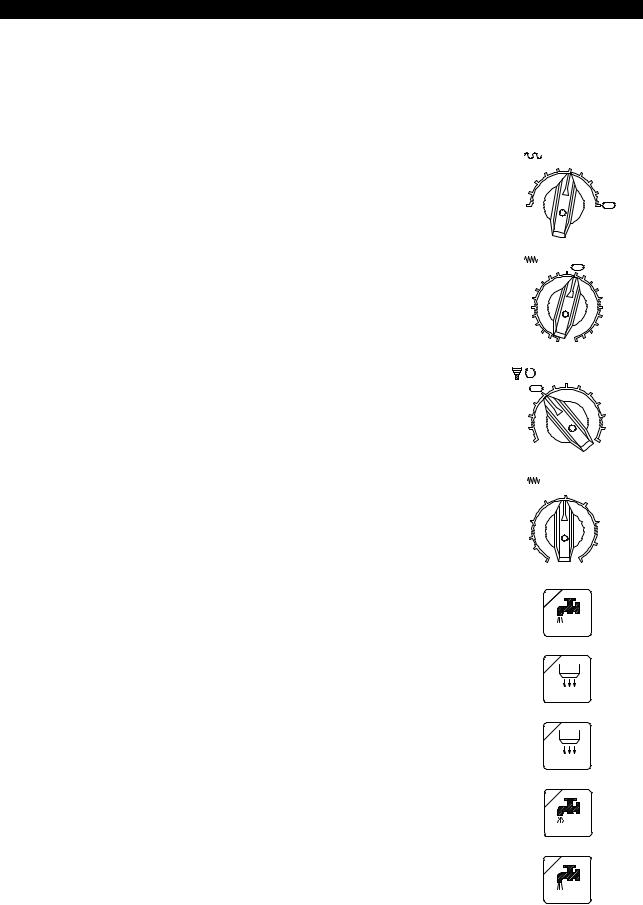
(17)RAPID OVERRIDE Dial
Used to set the desired override value to be applied to the rapid |
% |
RAPID |
|
OVERRIDE |
|||
traverse rate. |
10 |
30 |
50 |
|
70 |
||
|
|
||
|
5 |
|
80 |
|
1 |
|
90 |
|
0 |
|
100 |
(18) FEEDRATE Override Dial |
|
% FEEDRATE |
|
Used to set the desired override value to be applied to the feedrate |
|
||
80 |
90 |
95 100 |
|
specified in a program. |
|
105 |
|
70 |
|
110 |
|
|
|
||
|
60 |
|
120 |
|
50 |
|
130 |
|
40 |
|
140 |
|
30 |
|
150 |
|
20 |
|
160 |
|
10 |
|
170 |
|
5 |
0 |
200 180 |
(19)SPINDLE OVERRIDE Dial
Used to set the desired override value to be applied to the spindle speed specified in a program.
(20)JOG SPEED Dial
The [JOG SPEED] dial is used to set jog feedrate (cutting feedrate).
(21)COOLANT Key
Used to turn on coolant supply.
% SPINDLE OVERRIDE
|
|
100 |
110 |
120 |
|
130 |
|
|
|
|
|
|
|
140 |
|
|
|
|
|
90 |
|
|
|
|
150 |
|
|
80 |
|
|
|
|
160 |
|
|
|
70 |
|
|
|
|
180 |
|
|
|
|
50 |
|
|
|
|
200 |
|
|
|
|
(inch/min) |
JOG |
|
|
||
|
|
|
(mm/min) |
SPEED |
|
|||
|
|
|
1000 |
40 |
|
|
||
|
|
20 500 |
|
|
2000 |
80 |
|
|
8 |
200 |
|
|
|
|
4000 |
160 |
|
4 |
100 |
|
|
|
6000 |
240 |
||
|
2 |
50 |
|
|
|
|||
|
|
|
|
|
|
|
||
|
|
0.04 |
1 |
|
|
10000 |
400 |
|
COOLANT
(22) A.B NOZ. Key
A. B NOZ.
(23) A.B ADAPT. Key
A. BADAPT.
(24) OIL MIST Key
OIL MIST
(25) OIL HOLE Key
OIL HOLE
4290-E P-9
SECTION 1 PART NAMES AND FUNCTION
(26) OIL HOLE HIGH Key
OIL HOLE
HIGH
(27) SHOWER Key
SHOWER
(28) LIGHT Key
LIGHT
(29) LUB. Key
LUB.
(30) CHIP CON. Reverse Key
Used to operate the chip conveyor in the reverse direction. The chip conveyor operates only while the key is pressed.
CHIP CON.
(31) CHIP CON. Forward Key
Used to operate the chip conveyor in the forward direction.
CHIP CON.
(32)DISPLAY OFF Key
While this function is in effect, the indicating lamp at the upper left corner of the key is lit.
(33)Door Interlock Mode Selector Switch
For details of the door interlock function, refer to the Instruction Manual for Safety Door Interlock Function separately issued.
DISPLAY
OFF
PRODUCTION
SETTING TEST

4290-E P-10
SECTION 1 PART NAMES AND FUNCTION
1-2-6. Mode Selection Keys
These switches are used to select the operation mode for program operation.
(1)SINGLE BLOCK Key
Used to execute a program block by block.
When this key is valid, the indicating lamp at the upper left corner lights.
The [CYCLE START] button has to be pressed to execute each successive block.
When the [SINGLE BLOCK] key is invalid (indicating lamp at the upper left corner unlit), program blocks are executed continuously.
(2)BLOCK SKIP Key
Used to ignore the commands between a slash (/) code and “CR” code.
When this key is valid, the indicating lamp at the upper left corner lights.
When the [BLOCK SKIP] key is invalid (indicating lamp at the upper left corner unlit), commands entered after a slash code (/) are executed.
[Supplement]
SINGLE BLOCK
BLOCK
SKIP
A slash code (/) must be placed at the start of a program block or immediately after the sequence number (or sequence name) of a block.
(3)PROGRAM BRANCH Key
Used to execute a program branch instruction in a part program. The indicating lamp at the upper left corner of the key is lit when the program branch function is valid.
When the [PROGRAM BRANCH] key is invalid (indicating lamp at the upper left corner of the key unlit), a program branch instruction in a part program is not executed.
(4)OPTIONAL STOP Key
Used to stop program operations including spindle rotation and coolant supply.
When this key is valid, the indicating lamp at the upper left corner lights.
Pressing the [CYCLE START] button in this condition recovers the state before the stop and starts continuous program execution. When the [OPTIONAL STOP] key is invalid (indicating lamp at the upper left corner unlit), program execution proceeds even if a block containing M01 is executed.
(5)CYCLE STOP Key
Used to stop the operation after the completion of a main program while the operation is controlled by a schedule program.
When this key is valid, the indicating lamp at the upper left corner lights.
When the [CYCLE STOP] key is invalid (indicating lamp at the upper left corner unlit), the operation continues even after the completion of a main program while the operation is controlled by a schedule program.
PROGRAM PROGRAM
BRANCH |
BRANCH |
1 |
2 |
OPTIONAL
STOP
CYCLE
STOP

|
|
4290-E P-11 |
|
SECTION 1 PART NAMES AND FUNCTION |
|
(6) AXIS COM. CANCEL Key |
|
|
|
Used to cancel the operation of the specified axis. Designation of an |
AXIS |
|
axis made using a parameter. |
|
|
COM. |
|
|
When the [AXIS COM. CANCEL] key is valid, the indicating lamp at |
CANCEL |
|
the upper left corner lights. |
|
(7) |
S.T.M LOCK Key |
|
|
Used to lock miscellaneous functions and enable only axis move- |
|
|
ments. |
S. T. M. |
|
|
LOCK |
(8) |
DRY RUN Key |
|
|
Used to execute axis feed commands (commands in G01, G02, G03 |
|
|
mode, etc.) at the feedrate set with the JOG SPEED dial. The fee- |
|
|
drate commands specified in a program are disregarded. |
|
|
When the [DRY RUN] key is valid, the indicating lamp at the upper |
DRY |
|
left corner lights. |
|
|
RUN |
|
When the [DRY RUN] key is invalid (indicating lamp at the upper left corner unlit), the axes are fed at the feedrates specified in the program.
[Supplement]
To change the dry run function ON/OFF state, press the [DRY RUN] key while holding down the [INTERLOCK RELEASE] key.
(9)MACHINE LOCK Key
Used to execute a program without actual machine operations. When the [MACHINE LOCK] key is valid, the indicating lamp at the upper left corner lights.
If a program is executed with the machine lock function ON, the actual position display is updated according to the commands as the program is run. The block data display is also updated. Resetting the CNC restores the display prior to the machine lock.
When the [MACHINE LOCK] key is invalid (indicating lamp at the upper left corner unlit), commands specifying machine operations are actually executed.
[Supplement]
MACHINE
LOCK
To change the machine lock function ON/OFF state, press the [MACHINE LOCK] key while holding down the [INTERLOCK RELEASE] key.
(10)MIRROR IMAGE Keys
Used to reverse the sign of the coordinate value.
When the [MIRROR IMAGE] key is valid, the indicating lamp at the upper left corner lights.
When the [MIRROR IMAGE] key is invalid (indicating lamp at the upper left corner unlit), the sign of the specified coordinate value is not reversed.
[Supplement]
MIRROR |
MIRROR |
MIRROR |
MIRROR |
IMAGE |
IMAGE |
IMAGE |
IMAGE |
X |
Y |
Z |
4 |
To change the mirror image function ON/OFF state, press the [MIRROR IMAGE] key while holding down the [INTERLOCK] key.

4290-E P-12
SECTION 1 PART NAMES AND FUNCTION
(11)INTERLOCK RELEASE Key
This key must be held down when the corresponding mode key is pressed in order to establish or cancel the dry run mode, machine lock mode or mirror image mode.
The indicating lamp at the upper left corner of the key is lit, and the key function is valid, only while the key is pressed.
(12)SEQUENCE RESTART Key
Used during program operation to start a part program from part way through.
When performing manual operation by interrupting an automatic operation by pressing the [MID AUTO MANUAL] key, the axes can be returned to the position where automatic operation was interrupted by pressing the [SEQUENCE RESTART] key.
(13)MID AUTO MANUAL Key
Used to interrupt automatic or MDI mode operation to perform manual operation.
INTER
LOCK
RELEASE
SEQUENCE RESTART
MID.
AUTO
MANUAL
(14)PULSE HANDLE SHIFT Key
Used to add axis movements performed by turning the pulse handle to the operation executed according to the commands in a part program.
PULSE HANDLE SHIFT
2.SCREENS
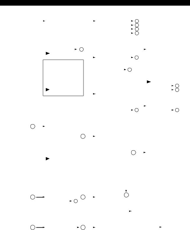
2-1. Mode Transition Charts
Note that the screens displayed depend on the machine specifications.
4290-E P-13
SECTION 1 PART NAMES AND FUNCTION
2-1-1. Operation Modes (Automatic / MDI / Manual)
ACTUAL POSITION |
|
|
|
|
|
F1 |
MAIN PRG_OPER |
|
|
|
|
F1 |
PROGRAM SELECT |
|
2 |
|
|
|
|
|
|
|
|
|
|
||||||||||
|
|
|
|
|
|
|
|
|
|
|
|
|
|
|
|
|
|||||||||||||||||||
MAIN PROGRAM |
|
|
|
|
|
F2 |
ACT_POSI ENLARGE |
|
|
|
|
F2 |
RESTART |
|
5 |
|
|
|
|
|
|
|
|
|
|
||||||||||
SCHEDULE PROGRAM |
|
|
|
F3 |
LOAD ON/OFF |
|
|
|
|
F3 |
NUMBER STOP |
|
4 |
|
|
|
|
|
|
|
|
|
|
||||||||||||
|
|
|
|
|
|
|
|
|
|
|
|
|
|
|
|
|
|
||||||||||||||||||
MDI PROGRAM |
|
|
|
|
F4 |
ANIMATE ON/OFF |
|
|
|
|
F4 |
NUMBER SEARCH |
|
3 |
|
|
|
|
|
|
|
|
|
|
|||||||||||
|
|
|
|
|
|
|
|
|
|
|
|
|
|
|
|
|
|
|
|||||||||||||||||
FEED AXIS DATA |
|
|
|
|
F5 |
PROGRAM ON/OFF |
|
|
|
|
F5 |
EXEC/READ |
|
|
|
|
|
|
|
|
|
|
|
|
|
|
|||||||||
|
|
|
|
|
|
|
|
|
|
|
|
|
|
|
|
|
|
|
|
||||||||||||||||
BLOCK DATA |
|
|
F6 |
QUICK EDIT |
|
|
|
|
F6 |
QUICK EDIT |
|
|
|
|
|
|
|
|
|
|
|
|
|
|
|||||||||||
|
|
|
|
|
|
|
|
|
|
|
|
|
|
|
|
|
|
|
|||||||||||||||||
|
|
|
|
|
|
F7 |
NC OPR MONITOR |
|
|
|
|
|
F7 |
MAIN PRG_EDIT |
|
|
|
|
|
|
|
|
|
|
|
|
|
|
|
|
|
||||
|
|
|
|
|
|
|
1 |
|
|
|
|
|
|
|
|
|
|
|
|
|
|
|
|
|
|
|
|
||||||||
|
|
|
|
|
|
F8 |
DISPLAY CHANGE |
|
|
|
|
|
|
F8 |
CLOSE |
|
|
|
|
|
|
F1 |
COPY |
|
|||||||||||
|
|
|
|
|
|
|
|
|
|
|
|
|
|
|
|
|
|
|
|
|
|
|
|
|
|
|
|
F2 |
DELETE |
|
|||||
|
|
|
|
|
|
F1 |
SCHEDULE PRG_OPR |
|
|
|
|
|
|
F1 |
PROGRAM SELECT |
|
2 |
|
|
F3 |
PASTE |
|
|||||||||||||
|
|
|
|
|
|
F2 |
LIBRARY PROGRAM |
|
|
|
|
F2 |
|
|
|
|
|
|
|
|
|
|
|
F4 |
1 LINE INSERT |
|
|||||||||
|
|
|
|
|
|
F3 |
|
|
|
|
|
|
|
|
|
F3 |
PROGRAM ENTRY |
|
|
|
|
|
|
|
|
|
F5 |
1-CHAR DELETE |
|
||||||
|
|
|
|
|
|
|
|
|
|
|
|
|
|
|
|
|
|
3 |
|
|
|
|
|
|
|||||||||||
|
|
|
|
|
|
F4 |
PROGRAM MESSAGE |
|
|
|
|
F4 |
NUMBER SEARCH |
|
|
|
|
|
|
|
|
F6 |
OVER WR/INSERT |
|
|||||||||||
|
|
|
|
|
|
|
|
|
|
|
|
|
|
|
|
|
|||||||||||||||||||
|
|
|
|
|
|
F5 |
TOOL ON/OFF |
|
|
|
|
F5 |
SCHEDULE PRG_EDIT |
|
|
|
|
|
|
F7 |
PROGRAM SELECT |
|
|||||||||||||
|
|
|
|
|
|
F6 |
TOOL LIST DISPLAY |
|
|
|
|
F6 |
QUICK EDIT |
|
|
|
|
|
|
F8 |
QUIT |
|
|||||||||||||
|
|
|
|
|
|
F7 |
|
|
|
|
|
|
|
|
|
F7 |
MAIN PRG_EDIT |
|
|
|
|
|
|
|
|
|
|
|
|
|
|
|
|
10 |
|
|
|
|
|
|
|
|
|
|
|
|
|
|
|
|
|
|
|
|
|
|
|
|
|
|
|
|
|
|
|
|
|||||
|
|
|
|
|
|
F8 |
DISPLAY CHANGE |
|
|
|
|
F8 |
CLOSE |
|
|
|
|
|
|
F1 |
FIND/REPLACE |
|
|
||||||||||||
|
|
|
|
|
|
|
|
|
|
|
|
|
|
|
|
|
|
|
|
|
|
|
|
|
|
|
|
F2 |
JUMP |
|
|
|
11 |
||
|
|
|
|
|
|
|
|
|
|
|
|
|
|
|
|
|
|
|
|
|
|
|
|
|
|
|
|
|
|
||||||
|
|
|
|
|
|
F1 |
PARAM.F1 SET |
|
|
|
|
F1 |
ACT. POSI (WORK) |
|
|
|
|
|
|
: |
|
|
|
|
|
|
|
||||||||
|
|
|
|
|
|
F2 |
* Refer to next page. |
|
|
|
F2 |
ACT. POSI (LOCAL) |
|
|
|
|
|
|
F8 |
|
|
|
|
|
|
||||||||||
|
|
|
|
|
|
F3 |
|
|
|
|
|
|
|
|
|
F3 |
MACHINE ACT. POSI |
|
|
|
|
|
|
|
|
|
|
|
|
|
|
||||
|
|
|
|
|
|
: |
|
|
|
|
|
|
|
|
|
F4 |
RELATIVE ACT. POSI |
|
|
7 |
|
|
F1 |
|
|
|
|
|
3 |
||||||
|
|
|
|
|
|
F7 |
|
|
|
|
|
|
|
|
|
F5 |
POSI SET RELATIVE* |
|
|
|
F2 |
FILE NAME |
|
|
|
||||||||||
|
|
|
|
|
|
|
|
|
|
|
|
|
|
|
|
|
|
|
|
|
|||||||||||||||
|
|
|
|
|
|
F8 |
|
|
|
|
|
|
|
|
|
F6 |
SHIFT ON/OFF |
|
|
|
|
|
|
F3 |
SORT |
|
|||||||||
|
|
|
|
|
|
|
|
|
|
|
|
|
|
|
|
F7 |
|
|
|
|
|
|
|
|
|
|
|
F4 |
|
|
|
|
|
|
|
|
|
|
|
|
|
|
|
|
|
|
|
|
|
|
|
F8 |
CLOSE |
|
|
|
|
|
|
F5 |
|
|
|
|
|
|
|||||
1 |
|
|
|
|
|
F1 |
ACTUAL POSITION |
|
* Displayed |
only |
when [F4] (RELATIVE ACT. POSI) is selected. |
F6 |
ENTRY |
|
|||||||||||||||||||||
|
|
|
|
|
|
|
|||||||||||||||||||||||||||||
|
|
|
|
|
|
F2 |
MAIN PROGRAM |
|
|
|
|
|
|
|
|
|
|
|
|
|
|
|
|
F7 |
ENTRY CANCEL |
|
|||||||||
|
|
|
|
|
|
F3 |
SCHEDULE PROGRAM |
4 |
|
|
|
|
|
|
|
|
|
|
|
|
|
|
|
F8 |
CLOSE |
|
|||||||||
|
|
|
|
|
|
|
|
|
F1 |
|
|
|
|
|
|
|
|
|
|
|
|
||||||||||||||
|
|
|
|
|
|
F4 |
MDI PROGRAM |
|
|
|
|
|
|
|
|
|
|
|
|
|
|
|
|
|
|
|
|
|
|
||||||
|
|
|
|
|
|
|
|
|
|
F2 |
|
|
|
|
|
|
|
|
|
|
|
|
|
|
|
|
|
|
|
||||||
|
|
|
|
|
|
F5 |
ANIMATED SIMULATE |
|
|
|
|
|
|
|
|
|
|
|
|
|
|
|
|
|
|
|
|
|
|
|
|||||
|
|
|
|
|
|
|
|
|
|
: |
|
|
|
|
|
|
|
|
|
|
|
|
|
|
|
|
|
|
|
||||||
|
|
|
|
|
|
F6 |
|
|
|
|
|
|
|
|
|
|
|
|
|
|
|
|
|
|
|
|
|
|
|
|
|
|
|
|
|
|
|
|
|
|
|
|
|
|
|
|
|
|
|
|
F6 |
ENTRY |
|
|
|
|
|
|
|
|
|
|
|
|
|
|
|
||||
|
|
|
|
|
|
F7 |
|
|
|
|
|
|
|
|
|
|
7 |
|
|
|
|
|
|
|
|
|
|
|
|||||||
|
|
|
|
|
|
F8 |
CLOSE |
|
|
|
|
F7 |
ENTRY CANCEL |
|
|
|
|
F1 |
|
|
|
|
|
|
|
||||||||||
|
|
|
|
|
|
|
|
|
|
F8 |
CLOSE |
|
|
|
|
|
|
|
F2 |
|
|
|
|
|
|
|
|||||||||
|
|
|
|
|
|
|
|
|
|
|
|
|
|
|
|
|
|
|
|
|
|
|
|
|
|
|
|
|
|
||||||
|
|
|
|
|
|
|
|
|
|
|
|
|
|
|
|
|
|
|
|
|
|
|
|
|
|
|
|
F3 |
|
|
|
|
|
|
|
|
|
|
|
|
|
F1 |
MENU CHANGE |
|
|
|
|
|
|
|
|
|
|
|
|
|
|
|
|
|
|
|
|
|
|
||||||
|
|
|
|
|
|
|
|
|
|
|
|
|
|
|
|
|
|
|
|
|
|
: |
|
|
|
|
|
|
|
||||||
|
|
|
|
|
|
F2 |
DISPLAY PROPERTY |
|
|
|
|
|
|
|
|
|
|
|
|
|
|
|
|
|
|
|
|
|
|
|
|||||
|
|
|
|
|
|
|
|
|
|
|
|
|
|
|
|
|
|
|
|
|
|
F7 |
|
|
|
|
|
|
|
||||||
|
|
|
|
|
|
F3 |
|
|
|
|
|
|
|
|
|
|
|
|
|
|
|
|
|
|
|
|
|
|
|
|
|
|
|
|
|
|
|
|
|
|
|
|
|
|
|
|
|
|
|
|
|
|
|
|
|
|
|
|
|
|
|
|
F8 |
CLOSE |
|
||||||
|
|
|
|
|
|
F4 |
|
|
|
|
|
|
|
|
|
|
|
|
|
|
|
|
|
|
|
|
|
|
|||||||
|
|
|
|
|
|
|
|
|
|
|
|
|
|
|
|
|
|
|
|
|
|
|
|
|
|
|
|
|
|
|
|
|
|
|
|
|
|
|
|
|
|
F5 |
|
|
|
|
|
|
|
|
|
|
|
|
|
|
|
|
|
|
|
|
|
|
|
|
|
|
|
|
|
|
|
|
|
|
|
F6 |
|
|
|
|
|
|
|
|
|
|
|
|
|
|
|
|
|
|
|
|
|
|
|
|
|
|
|
|
|
|
|
|
|
|
|
F7 |
|
|
|
|
|
|
|
|
|
|
|
|
|
|
|
|
|
|
|
|
|
|
|
|
|
|
|
|
|
|
|
|
|
|
|
F8 |
CLOSE |
|
|
|
|
|
|
|
|
|
|
|
|
|
|
|
|
|
|
|
|
|
|
|
|
||||
|
|
|
|
|
|
|
|
|
|
|
|
|
|
|
|
|
|
|
|
|
|
|
|
|
|
|
|
|
|
||||||
2
3
|
|
|
5 |
|
|
|
|
18 |
|
|
|
|
|
||||
F1 |
|
|
|
|
F1 |
|
|
|
|
|
|
|
|
||||
F2 |
FILE NAME |
|
3 |
|
|
|
F2 |
|
|
|
|
|
|
|
|
||
|
|
|
|
|
|
|
|
|
|||||||||
F3 |
SORT |
|
|
|
|
|
|
|
: |
|
|
|
|
|
|
|
|
|
|
|
|
|
|
|
|
|
|
|
|
|
|
|
|||
: |
|
|
|
|
|
|
|
|
F6 |
LAST |
|
|
|
|
|
|
|
|
|
|
|
|
|
|
|
|
|
|
F1 |
SET |
|
|
|||
F7 |
OK |
|
|
|
|
|
|
F7 |
OK |
|
|
|
|
|
|||
|
|
|
|
|
|
|
|
|
F2 |
ADD |
|
|
|||||
F8 |
CANCEL |
|
|
|
|
|
|
F8 |
CLOSE |
|
|
|
|
|
|||
|
|
|
|
|
|
|
|
|
F3 |
|
|
|
|||||
|
|
|
|
|
|
|
|
|
|
|
|
|
|
|
|
|
|
|
|
|
|
|
|
|
|
|
|
|
|
|
|
F4 |
|
|
|
F1 |
|
|
|
|
6 |
|
|
F1 |
FILE NAME |
|
|
|
F5 |
RELATION PARA. |
F1 |
MENU |
|
|
|
|
|
|
|||||||||||||
F2 |
|
|
|
|
|
|
|
|
F2 |
SIZE |
|
|
|
F6 |
|
F2 |
|
F3 |
|
|
|
|
|
|
|
|
F3 |
DATE (UP) |
|
|
|
F7 |
BACKUP |
F3 |
|
: |
|
|
|
|
|
|
|
|
F4 |
DATE (DOWN) |
|
|
|
F8 |
CLOSE |
: |
|
F7 |
OK |
|
|
|
|
|
|
F5 |
EXT. |
|
|
|
|
|
: |
|
|
F8 |
CANCEL |
|
|
|
|
|
|
F6 |
|
|
|
|
|
|
: |
|
|
|
|
|
|
|
|
|
|
|
F7 |
UNSORT |
|
|
|
|
|
F7 |
BACKUP |
|
|
|
|
|
|
|
|
|
F8 |
CLOSE |
|
|
|
|
|
F8 |
CLOSE |
EIOEMM1B2025R01
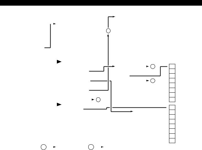
4290-E P-14
SECTION 1 PART NAMES AND FUNCTION
|
|
|
|
|
|
|
* Refer to previous page. |
|
|
F1 |
TOOL LIST SELECT |
|
|||||||
ACTUAL POSITION |
|
|
|
|
|
|
|
|
F2 |
LACK & DISUSED |
|
||||||||
|
|
|
|
|
|
|
|
|
|
|
|
||||||||
|
|
|
|
|
|
F1 |
MAIN PRG_OPER |
|
|
|
|||||||||
|
|
|
|
|
|
|
F3 |
|
|
|
|
|
|
|
|||||
MAIN PROGRAM |
|
|
|
|
|
|
F2 |
ACT_POSI ENLARGE |
|
16 |
|
|
|
|
|
|
|
||
|
|
|
|
|
|
|
F4 |
|
|
|
|
|
|
|
|||||
SCHEDULE |
|
|
|
|
|
|
F3 |
LOAD ON/OFF |
|
|
|
|
|
|
|
|
|||
|
|
|
|
|
|
|
|
F5 |
DATA CHANGE |
|
|||||||||
MDI PROGRAM |
|
|
|
|
|
|
F4 |
ANIMATE ON/OFF |
|
|
|
||||||||
|
|
|
|
|
|
|
|
F6 |
|
|
|
|
|
|
|
||||
FEED AXIS DATA |
|
|
|
|
|
|
F5 |
PROGRAM ON/OFF |
|
|
|
|
|
|
|
|
|
||
|
|
|
|
|
|
|
|
F7 |
|
|
|
|
|
|
|
||||
BLOCK DATA |
|
|
|
F6 |
QUICK EDIT |
|
|
|
|
|
|
|
|
|
|||||
|
|
|
|
|
F8 |
CLOSE |
|
||||||||||||
|
|
|
|
|
|
|
F7 |
NC OPR MONITOR |
|
|
|
||||||||
|
|
|
|
|
|
|
|
|
|
|
|
|
|
|
|
|
|||
|
|
|
|
|
|
|
F8 |
DISPLAY CHANGE |
|
|
|
|
|
|
|
|
|
|
|
|
|
|
|
|
|
|
|
|
|
|
|
|
|
|
|
|
|
|
2 |
|
|
|
|
|
|
|
|
|
|
|
|
|
|
|
|
|
|
|
|
|
|
|
|
|
|
|
|
|
|
|
|
|
|
|
|
|
|
|
|
|
|
|
|
|
|
|
F1 |
SCHEDULE PRG_OPER |
|
|
F1 |
REGIS. |
|
|
|
|
|
||
|
|
|
|
|
|
|
|
|
|
|
|
|
|||||||
|
|
|
|
|
|
|
F2 |
LIBRARY PROGRAM |
|
|
F2 |
ERASE |
|
|
|
|
|
||
|
|
|
|
|
|
|
|
|
|
|
|
|
|
||||||
|
|
|
|
|
|
|
F3 |
|
|
|
|
F3 |
INIT |
|
|||||
|
|
|
|
|
|
|
F4 |
PROGRAM MESSAGE |
|
|
F4 |
BUFFER SIZE |
|
|
3 |
||||
|
|
|
|
|
|
|
|
|
|
||||||||||
|
|
|
|
|
|
|
F5 |
TOOL ON/OFF |
|
|
F5 |
|
|
|
|
|
|
|
|
|
|
|
|
|
|
|
F6 |
TOOL LIST DISPLAY |
|
|
F6 |
|
|
|
|
|
|
|
|
|
|
|
|
|
|
|
F7 |
|
|
|
|
F7 |
|
|
|
|
|
|
|
|
|
|
|
|
|
|
F8 |
DISPLAY CHANGE |
|
1 |
|
F8 |
CLOSE |
|
|||||
|
|
|
|
|
|
|
|
|
|
||||||||||
|
|
|
|
|
|
|
|
|
|
|
|
|
|
|
|
|
|
|
|
|
|
|
|
|
|
|
F1 |
PARAM. F1 SET |
|
|
|
|
|
|
|
|
|
|
|
|
|
|
|
|
|
|
|
|
|
|
|
F1 |
|
|
|
|
|||
|
|
|
|
|
|
|
F2 |
|
|
|
|
|
|
|
|
|
|
|
|
|
|
|
|
|
|
|
|
|
|
|
|
|
|
F2 |
|
|
|
|
|
|
|
|
|
|
|
|
F3 |
|
|
|
|
|
|
|
|
|
|
|
|
|
|
|
|
|
|
|
|
|
|
|
|
|
|
: |
|
|
|
|
|
|
|
|
|
|
|
|
: |
|
|
|
|
|
|
|
|
|
|
|
|
|
|
|
|
|
|
|
|
|
|
|
|
F6 |
|
|
|
|
|||
|
|
|
|
|
|
|
F7 |
|
|
|
|
|
|
|
|
|
|
|
|
|
|
|
|
|
|
|
|
|
|
|
|
|
|
F7 |
|
|
|
|
|
|
|
|
|
|
|
|
F8 |
|
|
|
|
|
|
|
|
|
|
|
|
|
|
|
|
|
|
|
|
|
|
|
|
|
|
F8 |
CLOSE |
|
|||
|
|
|
|
|
|
|
|
|
|
|
|
|
|
|
|
||||
10 |
|
|
F1 |
|
11 |
|
|
F1 |
|
|
|
|
|
|
|
||||
|
|
|
F2 |
|
|
|
|
F2 |
|
|
|
|
F3 |
|
|
|
|
F3 |
TOP PAGE |
|
|
|
F4 |
|
|
|
|
F4 |
LAST PAGE |
|
|
|
F5 |
|
|
|
|
F5 |
FORWARD |
|
|
|
F6 |
FIND |
|
|
|
F6 |
BACK |
|
|
|
F7 |
REPLACE |
|
|
|
F7 |
TOP |
|
|
|
F8 |
CLOSE |
|
|
|
F8 |
CANCEL |
 F1
F1
F2
F3
F4
F5
F6 YES
F7 NO
F8
 F1 SET
F2 ADD
F3
F4 ACCEL
F5 DECEL
F6
F7 BACKUP
F8 CLOSE
EIOEMM1B2026R01
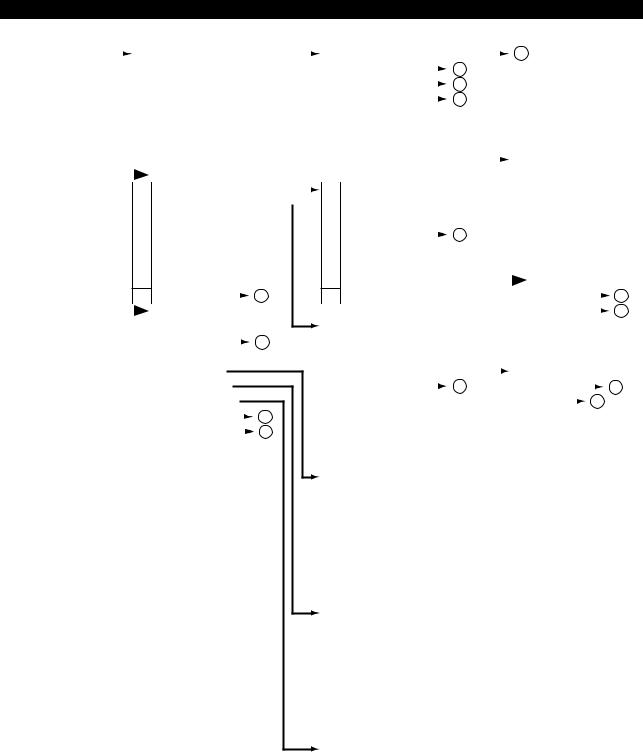
4290-E P-15
SECTION 1 PART NAMES AND FUNCTION
ANIMATED SIMULATION |
|
|
F1 |
MAIN PRG_OPER |
|
|
|
|
|
F1 |
PROGRAM SELECT |
|
|
|
|
|
|
|
|
2 |
|
||
|
|
|
|
|
|
|
|
|
|
|
|
|
|
||||||||||
< > : 3D MODE |
F2 |
TRACE/ANIMATE <TRACE/MATERIAL> |
F2 |
RESTART |
|
|
5 |
|
|
|
|
|
|||||||||||
|
|
|
|
|
|
|
|||||||||||||||||
|
|
|
F3 |
MATERIAL DRAWING |
F3 |
NUMBER STOP |
|
|
4 |
|
|
|
|
|
|||||||||
|
|
|
|
|
|
|
|
|
|
||||||||||||||
|
|
|
F4 |
ERASE |
F4 |
NUMBER SEARCH |
|
|
3 |
|
|
|
|
|
|||||||||
|
|
|
|
|
|
|
|
|
|
||||||||||||||
|
|
|
F5 |
PROGRAM ON/OFF |
F5 |
EXEC/READ |
|
|
|
|
|
|
|
|
|||||||||
|
|
|
F6 |
QUICK EDIT |
F6 |
QUICK EDIT |
|
|
|
|
|
|
|
|
|||||||||
|
|
|
F7 |
HIGH DRAW |
F7 |
MAIN PRG_EDIT |
|
|
|
|
|
|
|
|
|
|
|||||||
|
|
|
|
|
|
|
|
|
|
|
|
|
|||||||||||
|
|
|
F8 |
DISPLAY CHANGE |
F8 |
CLOSE |
|
|
|
|
|
|
F1 |
COPY |
|||||||||
|
|
|
|
|
|
|
|
|
|||||||||||||||
|
|
|
|
|
|
|
|
|
|
|
|
|
|
|
|
|
|
|
|
|
|
F2 |
DELETE |
|
|
|
F1 |
SCHEDULE PRG_OPER |
|
|
F1 |
PROGRAM SELECT |
|
|
|
|
|
|
|
|
F3 |
PASTE |
|||||
|
|
|
|
|
|
|
|
|
|
|
|
||||||||||||
|
|
|
F2 |
ACT_POSI ENLARGE |
|
|
|
|
F2 |
|
|
|
|
|
|
|
|
|
|
F4 |
1 LINE INSERT |
||
|
|
|
|
|
|
|
|
|
|
|
|
|
|
|
|||||||||
|
|
|
F3 |
LOAD ON/OFF |
F3 |
PROGRAM ENTRY |
|
|
|
|
|
|
|
|
|
F5 |
1-CHAR DELETE |
||||||
|
|
|
|
|
|
|
3 |
|
|
|
|||||||||||||
|
|
|
F4 |
TOOL ON/OFF |
F4 |
NUMBER SEARCH |
|
|
|
|
|
F6 |
OVER WR/INSERT |
||||||||||
|
|
|
|
|
|
|
|
||||||||||||||||
|
|
|
F5 |
SPLIT/SOLID <SECTION ON/OFF> |
F5 |
SCHEDULE PRG EDIT |
|
|
|
|
|
|
F7 |
PROGRAM SELECT |
|||||||||
|
|
|
F6 |
<TRNSPRNT ON/OFF> |
F6 |
QUICK EDIT |
|
|
|
|
|
|
F8 |
QUIT |
|||||||||
|
|
|
F7 |
AUTO SCALE |
F7 |
MAIN PRG_EDIT |
|
|
|
|
|
|
|
|
|
|
|||||||
|
|
|
|
|
|
|
|
|
|
|
|
|
|||||||||||
F8 |
DISPLAY CHANGE |
|
|
|
|
1 |
|||
|
|
|
|
||||||
|
|
|
|
|
|
|
|
|
|
F1 |
2D/3D CHANGE |
|
|
|
|
||||
F2 |
RESTART |
|
|
|
5 |
||||
|
|
|
|||||||
F3 |
GRAPHIC DATA |
|
|
|
|
||||
F4 |
AREA CHANGE |
|
|
|
|
||||
F5 |
<ANGLE CHANGE>* |
|
|
|
|
||||
F6 |
<SECTION CHANGE> |
|
|
|
|
||||
F7 |
NC OPR MONITOR |
|
|
|
|
8 |
|||
|
|
|
|
||||||
F8 |
DISPLAY CHANGE |
|
|
1 |
|||||
|
|
||||||||
*Displayed only when a solid drawing is selected with SPLIT/SOLID in 2D mode.
F8 |
CLOSE |
|
|
|
|
F1 |
FIND/REPLACE |
|
|
10 |
||||
|
|
|
|
|
|
|||||||||
|
|
|
|
|
|
F2 |
JUMP |
|
|
|
11 |
|||
|
|
|
|
|
|
|
|
|
||||||
F1 |
ACT. POSI (WORK) |
|
|
|
|
: |
|
|
|
|
|
|
|
|
F2 |
ACT. POSI (LOCAL) |
|
|
|
|
F8 |
|
|
|
|
|
|
|
|
F3 |
MACHIN ACT. POSI |
|
|
|
|
|
|
|
|
|
|
|
|
|
F4 |
RELATIVE ACT. POSI |
|
7 |
|
|
F1 |
|
|
|
|
|
|
3 |
|
|
|
|
|
|
|
|
|
|
||||||
F5 |
POSI SET RELATIVE* |
|
|
|
F2 |
FILE NAME |
|
|
||||||
|
|
|
|
|
||||||||||
F6 |
SHIFT ON/OFF |
|
|
|
|
F3 |
SORT |
|
|
6 |
|
|||
|
|
|
|
|
|
|||||||||
F7 |
|
|
|
|
|
F4 |
|
|
|
|
|
|
|
|
F8 |
CLOSE |
|
|
|
|
F5 |
|
|
|
|
|
|
|
|
* Displayed only when [F4] (RELATIVE ACT. POSI) |
F6 |
ENTRY |
|
|
|
|||||||||
is selected. |
|
|
|
|
F7 |
ENTRY CANCEL |
|
|
|
|||||
F1 |
MAGNI. |
|
|
|
|
F8 |
CLOSE |
|
|
|
||||
F2 |
REDUCE |
|
|
|
|
|
|
|
|
|
|
|
|
|
F3 |
|
|
|
|
|
|
|
|
|
|
|
|
|
|
F4 |
PLANE/SIDE <NONE> |
|
|
|
|
|
|
|
|
|
|
|
|
|
F5 |
|
|
|
|
|
|
|
|
|
|
|
|
|
|
F6 |
|
|
|
|
|
|
|
|
|
|
|
|
|
|
F7 |
|
|
|
|
|
|
|
|
|
|
|
|
|
|
F8 |
CLOSE |
|
|
|
|
|
|
|
|
|
|
|
|
|
|
|
|
|
|
|
|
|
|
|
|
|
|
|
|
F1 |
DOWN ROTARY |
|
|
|
|
|
|
|
|
|
|
|
|
|
F2 |
UP ROTARY |
|
|
|
|
|
|
|
|
|
|
|
|
|
F3 |
RIGHT ROTARY |
|
|
|
|
|
|
|
|
|
|
|
|
|
F4 |
LEFT ROTARY |
|
|
|
|
|
|
|
|
|
|
|
|
|
F5 |
|
|
|
|
|
|
|
|
|
|
|
|
|
|
F6 |
|
|
|
|
|
|
|
|
|
|
|
|
|
|
F7 |
|
|
|
|
|
|
|
|
|
|
|
|
|
|
F8 |
CLOSE |
|
|
|
|
|
|
|
|
|
|
|
|
|
|
|
|
|
|
|
|
|
|
|
|
|
|
|
|
F1 |
Y-Z PL. |
|
|
|
|
|
|
|
|
|
|
|
|
|
F2 |
Z-X PL. |
|
|
|
|
|
|
|
|
|
|
|
|
|
F3 |
X-Y PL. |
|
|
|
|
|
|
|
|
|
|
|
|
|
F4 |
|
|
|
|
|
|
|
|
|
|
|
|
|
|
F5 |
|
|
|
|
|
|
|
|
|
|
|
|
|
|
F6 |
|
|
|
|
|
|
|
|
|
|
|
|
|
|
F7 |
|
|
|
|
|
|
|
|
|
|
|
|
|
|
F8 |
CLOSE |
|
|
|
|
|
|
|
|
|
|
|
|
|
EIOEMM1B2027R01

4290-E P-16
SECTION 1 PART NAMES AND FUNCTION
GAUGING RESULTS |
|
|
|
F1 |
MAIN PRG_OPER |
|
|
|
|
|
|
|
|
|
|
F1 |
PROGRAM SELECT |
|
|
|
|
|
|
|
2 |
|
|
|
|
|
|
|
|
|
|
|
|
|
|||||||||||||||
|
|
|
|
|
|
|
|
|
|
|
|
|
|
|
|
|
|
|
|
|
|
|
|
|
|
|
|
||||||||||||||||||||||||||
|
|
|
|
F2 |
ACT_POSI ENLARGE |
|
|
|
|
|
|
|
|
|
|
F2 |
RESTART |
|
|
|
|
|
|
|
5 |
|
|
|
|
|
|
|
|
|
|
|
|
|
|||||||||||||||
|
|
|
|
|
|
|
|
|
|
|
|
|
|
|
|
|
|
|
|
|
|
|
|
|
|
|
|
|
|
|
|
|
|
||||||||||||||||||||
|
|
|
|
F3 |
LOAD ON/OFF |
|
|
|
|
|
|
|
|
|
|
F3 |
NUMBER STOP |
|
|
|
|
|
|
|
4 |
|
|
|
|
|
|
|
|
|
|
|
|
|
|||||||||||||||
|
|
|
|
|
|
|
|
|
|
|
|
|
|
|
|
|
|
|
|
|
|
|
|
|
|
|
|
|
|
|
|
|
|
||||||||||||||||||||
|
|
|
|
F4 |
ANIMATE ON/OFF |
|
|
|
|
|
|
|
|
|
|
F4 |
NUMBER SEARCH |
|
|
|
|
|
|
|
3 |
|
|
|
|
|
|
|
|
|
|
|
|
|
|||||||||||||||
|
|
|
|
|
|
|
|
|
|
|
|
|
|
|
|
|
|
|
|
|
|
|
|
|
|
|
|
|
|
|
|
|
|
||||||||||||||||||||
|
|
|
|
F5 |
PROGRAM ON/OFF |
|
|
|
|
|
|
|
|
|
|
F5 |
EXEC/READ |
|
|
|
|
|
|
|
|
|
|
|
|
|
|
|
|
|
|
|
|||||||||||||||||
|
|
|
|
F6 |
QUICK EDIT |
|
|
|
|
|
|
|
|
|
|
F6 |
QUICK EDIT |
|
|
|
|
|
|
|
|
|
|
|
|
|
|
|
|
|
|
|
|||||||||||||||||
|
|
|
|
F7 |
|
|
|
|
|
|
|
|
|
|
|
|
1 |
|
|
|
|
F7 |
MAIN PRG_EDIT |
|
|
|
|
|
|
|
|
|
|
|
|
|
|
|
|
|
|
|
|
|
|
|
|
|
|
|
|
||
|
|
|
|
|
|
|
|
|
|
|
|
|
|
|
|
|
|
|
|
|
|
|
|
|
|
|
|
|
|
|
|
|
|
|
|
|
|
|
|
|
|
|
|
|
|
|
|
||||||
|
|
|
|
F8 |
DISPLAY CHANGE |
|
|
|
|
|
|
|
|
|
|
F8 |
CLOSE |
|
|
|
|
|
|
|
|
F1 |
COPY |
|
|
|
|
|
|||||||||||||||||||||
|
|
|
|
|
|
|
|
|
|
|
|
|
|
|
|
|
|
|
|
|
|
|
|
|
|
|
|||||||||||||||||||||||||||
|
|
|
|
|
|
|
|
|
|
|
|
|
|
|
|
|
|
|
|
|
|
|
|
|
|
|
|
|
|
|
|
|
|
|
|
|
|
|
|
|
|
|
F2 |
DELETE |
|
|
|
|
|
||||
|
|
|
|
F1 |
SCHEDULE PRG_OPER |
|
|
|
|
|
|
F1 |
PROGRAM SELECT |
|
|
|
|
|
|
|
2 |
|
|
F3 |
PASTE |
|
|
|
|
|
|||||||||||||||||||||||
|
|
|
|
F2 |
TOOL/ZERO |
|
|
|
|
|
|
7 |
|
|
|
|
|
|
|
|
F2 |
|
|
|
|
|
|
|
|
|
|
|
|
|
|
|
|
|
|
|
|
F4 |
1 LINE INSERT |
|
|||||||||
|
|
|
|
|
|
|
|
|
|
|
|
|
|
|
|
|
|
|
|
|
|
|
|
|
|
|
|
|
|||||||||||||||||||||||||
|
|
|
|
F3 |
TOOL ON/OFF |
|
|
|
|
|
|
|
|
|
|
F3 |
PROGRAM ENTRY |
|
|
|
|
|
|
|
|
|
|
|
|
|
|
F5 |
1-CHAR DELETE |
|
|||||||||||||||||||
|
|
|
|
|
|
|
|
|
|
|
|
|
|
|
|
|
|
|
|
3 |
|
|
|
|
|
|
|||||||||||||||||||||||||||
|
|
|
|
F4 |
MSB ZERO ON/OFF |
|
|
|
|
|
|
|
|
|
|
F4 |
NUMBER SEARCH |
|
|
|
|
|
|
|
|
|
F6 |
OVER WR/INSERT |
|
||||||||||||||||||||||||
|
|
|
|
|
|
|
|
|
|
|
|
|
|
|
|
|
|
|
|
|
|||||||||||||||||||||||||||||||||
|
|
|
|
F5 |
MSB TOOL ON/OFF |
|
|
|
|
|
|
|
|
|
|
F5 |
SCHEDULE PRG_OPER |
|
|
|
|
|
|
|
|
F7 |
PROGRAM SELECT |
|
|||||||||||||||||||||||||
|
|
|
|
F6 |
SENSstat ON/OFF |
|
|
|
|
|
|
|
|
|
|
F6 |
QUICK EDIT |
|
|
|
|
|
|
|
|
F8 |
QUIT |
|
|
|
|
|
|||||||||||||||||||||
|
|
|
|
F7 |
VARIOUS ON/OFF |
|
|
|
|
|
1 |
|
|
|
|
F7 |
MAIN PRG_EDIT |
|
|
|
|
|
|
|
|
|
|
|
|
|
|
|
|
|
|
|
|
|
|
|
|
|
|
|
|
|
10 |
||||||
|
|
|
|
|
|
|
|
|
|
|
|
|
|
|
|
|
|
|
|
|
|
|
|
|
|
|
|
|
|
|
|
|
|
|
|
|
|
|
|
||||||||||||||
|
|
|
|
F8 |
DISPLAY CHANGE |
|
|
|
|
|
|
|
|
|
|
|
F8 |
CLOSE |
|
|
|
|
|
|
|
|
F1 |
FIND/REPLACE |
|
|
|||||||||||||||||||||||
|
|
|
|
|
|
|
|
|
|
|
|
|
|
|
|
|
|
|
|
|
|
|
|
|
|
|
|
|
|
|
|
|
|
|
|
|
|
|
|
|
|
|
F2 |
JUMP |
|
|
|
|
11 |
||||
|
|
|
|
|
|
|
|
|
|
|
|
|
|
|
|
|
|
|
|
|
|
|
|
|
|
|
|
|
|
|
|
|
|
|
|
|
|
|
|
|
|
|
|
|
|
|
|||||||
|
|
|
|
|
|
|
|
|
|
|
|
|
|
|
|
|
|
|
|
|
|
F1 |
ACT. POSI (WORK) |
|
|
|
|
|
|
|
|
: |
|
|
|
|
|
|
|
|
|
|
|||||||||||
|
|
|
|
|
|
|
|
|
|
|
|
|
|
|
|
|
|
|
|
|
|
|
|
|
|
|
|
|
|
|
|
|
|
|
|
|
|
|
|
||||||||||||||
|
|
|
|
|
|
|
|
|
|
|
|
|
|
|
|
|
|
|
|
|
|
F2 |
ACT. POSI (LOCAL) |
|
|
|
|
|
|
|
|
F8 |
|
|
|
|
|
|
|
|
|
|
|||||||||||
|
|
|
|
|
|
|
|
|
|
|
|
|
|
|
|
|
|
|
|
|
|
F3 |
MACHINE ACT. POSI |
|
|
|
|
|
|
|
|
|
|
|
|
|
|
|
|
|
|
|
|||||||||||
|
|
|
|
|
|
|
|
|
|
|
|
|
|
|
|
|
|
|
|
|
|
F4 |
RELATIVE ACT. POSI |
|
|
|
|
|
|
|
|
F1 |
|
|
|
|
|
|
|
|
|
|
|||||||||||
|
|
|
|
|
|
|
|
|
|
|
|
|
|
|
|
|
|
|
|
|
|
F5 |
POSI SET RELATIVE* |
|
|
|
|
|
|
|
7 |
|
|
F2 |
FILE NAME |
|
|
|
|
3 |
|||||||||||||
|
|
|
|
|
|
|
|
|
|
|
|
|
|
|
|
|
|
|
|
|
|
|
|
|
|
|
|
|
|
|
|
|
|
|
|||||||||||||||||||
|
|
|
|
|
|
|
|
|
|
|
|
|
|
|
|
|
|
|
|
|
|
F6 |
SHIFT ON/OFF |
|
|
|
|
|
|
|
|
F3 |
SORT |
|
|
|
|
6 |
|||||||||||||||
|
|
|
|
|
|
|
|
|
|
|
|
|
|
|
|
|
|
|
|
|
|
|
|
|
|
|
|
|
|
|
|
|
|
||||||||||||||||||||
|
|
|
|
|
|
|
|
|
|
|
|
|
|
|
|
|
|
|
|
|
|
F7 |
|
|
|
|
|
|
|
|
|
|
|
|
|
|
|
|
|
|
|
|
F4 |
|
|
|
|
|
|
|
|
|
|
|
|
|
|
|
|
|
|
|
|
|
|
|
|
|
|
|
|
|
|
|
|
F8 |
CLOSE |
|
|
|
|
|
|
|
|
F5 |
|
|
|
|
|
|
|
|
|
|
|||||||||||
|
|
|
|
|
|
|
|
|
|
|
|
|
|
|
|
|
|
|
|
|
|
* Displayed only when [F4] (RELATIVE ACT. POSI) |
F6 |
ENTRY |
|
|
|
|
|
||||||||||||||||||||||||
|
|
|
|
|
|
|
|
|
|
|
|
|
|
|
|
|
|
|
|
|
|
is selected. |
|
|
|
|
|
|
|
|
F7 |
ENTRY CANCEL |
|
||||||||||||||||||||
|
|
|
|
|
|
|
|
|
|
|
|
|
|
|
|
|
|
|
|
|
|
|
|
|
|
|
|
|
|
|
|
|
|
|
|
|
|
|
|
|
|
|
F8 |
CLOSE |
|
|
|
|
|
||||
NC AXIS DATA |
|
|
|
|
|
|
|
|
|
|
|
|
|
|
|
|
|
|
|
|
|
MEMORY DATA |
|
|
|
|
|
|
|
|
|
|
|
|
|
|
|
|
|
|
|
|
|
|
|
|
|
|
|||||
|
|
|
F1 |
STANDARD |
|
|
|
|
|
|
|
|
|
|
|
|
|
|
|
|
|
|
|
F1 |
REFER/CHANGE |
|
|
|
|
|
|||||||||||||||||||||||
|
|
|
|
|
|
|
|
|
|
|
|
|
|
|
|
|
|
|
|
|
|
|
|
||||||||||||||||||||||||||||||
|
|
|
|
F2 |
MAGNI. |
|
|
|
|
|
|
|
|
|
|
|
|
|
|
|
|
|
|
|
|
|
|
|
|
|
F2 |
ADDRESS UP |
|
|
|
|
|
|
|
|
|
|
|||||||||||
|
|
|
|
F3 |
|
|
|
|
|
|
|
|
|
|
|
|
|
|
|
|
|
|
|
|
|
|
|
|
|
|
|
|
|
|
|
|
F3 |
ADDRESS DOWN |
|
|
|
|
|
||||||||||
|
|
|
|
F4 |
|
|
|
|
|
|
|
|
|
|
|
|
|
|
|
|
|
|
|
|
|
|
|
|
|
|
|
|
|
|
|
|
F4 |
|
|
|
|
|
|
|
|
|
|
|
|
|
|
|
|
|
|
|
|
F5 |
|
|
|
|
|
|
|
|
|
|
|
|
|
|
|
|
|
|
|
|
|
|
|
|
|
|
|
|
|
|
|
|
F5 |
|
|
|
|
|
|
|
|
|
|
|
|
|
|
|
|
|
|
|
|
F6 |
|
|
|
|
|
|
|
|
|
|
|
|
|
|
|
|
|
|
|
|
|
|
|
|
|
|
|
|
|
|
|
|
F6 |
|
|
|
|
|
|
|
|
|
|
|
|
|
|
|
|
|
|
|
|
F7 |
|
|
|
|
|
|
|
|
|
|
|
|
|
|
|
|
|
|
|
|
|
|
|
|
|
|
|
|
|
|
|
|
F7 |
|
|
|
|
|
|
|
|
|
|
|
|
|
|
|
|
|
|
|
|
F8 |
DISPLAY CHANGE |
|
|
|
|
|
|
|
|
1 |
|
|
|
|
|
|
|
|
|
|
|
|
|
|
|
|
|
|
|
F8 |
|
DISPLAY CHANGE |
|
|
|
1 |
|
|
|
|
|||||||||
|
|
|
|
|
|
|
|
|
|
|
|
|
|
|
|
|
|
|
|
|
|
|
|
|
|
|
|
|
|
|
|
||||||||||||||||||||||
|
|
|
|
|
|
|
|
|
|
|
|
|
|
|
|
|
|
|
|
|
|
|
|
|
|
|
|
|
|
|
|
|
|
|
|
|
|
|
|
|
|
|
|
|
|
|
|||||||
DIAGNOSIS |
|
|
|
F1 |
REFER/CHANGE |
|
|
|
|
|
|
|
|
|
|
M CODE DISPLAY |
|
|
|
|
|
|
F1 |
|
|
|
|
|
|
|
|
|
|
|
|
|
|
|
|||||||||||||||
|
|
|
|
|
|
|
|
|
|
|
|
|
|
|
|
|
|
|
|
|
|
|
|
|
|
|
|
|
|
|
|
||||||||||||||||||||||
|
|
|
|
F2 |
|
|
|
|
|
|
|
|
|
|
|
|
|
|
|
|
|
|
|
|
|
|
|
|
|
|
|
|
|
|
|
|
F2 |
|
|
|
|
|
|
|
|
|
|
|
|
|
|
|
|
|
|
|
|
F3 |
|
|
|
|
|
|
|
|
|
|
|
|
|
|
|
|
|
|
|
|
|
|
|
|
|
|
|
|
|
|
|
|
F3 |
|
|
|
|
|
|
|
|
|
|
|
|
|
|
|
|
|
|
|
|
F4 |
|
|
|
|
|
|
|
|
|
|
|
|
|
|
|
|
|
|
|
|
|
|
|
|
|
|
|
|
|
|
|
|
F4 |
|
SEARCH |
|
|
|
|
|
|
|
|
|
|
|
|||
|
|
|
|
F5 |
|
|
|
|
|
|
|
|
|
|
|
|
|
|
|
|
|
|
|
|
|
|
|
|
|
|
|
|
|
|
|
|
F5 |
|
|
|
|
|
|
|
|
|
|
|
|
|
|
|
|
|
|
|
|
F6 |
|
|
|
|
|
|
|
|
|
|
|
|
|
|
|
|
|
|
|
|
|
|
|
|
|
|
|
|
|
|
|
|
F6 |
|
|
|
|
|
|
|
|
|
|
|
|
|
|
|
|
|
|
|
|
F7 |
|
|
|
|
|
|
|
|
|
|
|
|
|
|
|
|
|
|
|
|
|
|
|
|
|
|
|
|
|
|
|
|
F7 |
|
|
|
|
|
|
|
|
|
|
|
|
|
|
|
|
|
|
|
|
F8 |
DISPLAY CHANGE |
|
|
|
|
|
|
|
|
1 |
|
|
|
|
|
|
|
|
|
|
|
|
|
|
|
|
|
|
|
F8 |
|
DISPLAY CHANGE |
|
|
1 |
|
|
|
|
||||||||||
|
|
|
|
|
|
|
|
|
|
|
|
|
|
|
|
|
|
|
|
|
|
|
|
|
|
|
|
|
|
|
|
|
|
|
|
||||||||||||||||||
PLC DATA DISPLAY |
|
|
|
|
|
|
|
|
|
|
|
|
|
|
|
|
|
|
|
|
|
PLC MODULE SKIP |
|
|
|
|
|
|
|
|
|
|
|
|
|
|
|
|
|
|
|
|
|
|
|
|
|
|
|
||||
|
|
|
F1 |
(BIT ON) |
|
|
|
|
|
|
|
|
|
|
|
|
|
|
F1 |
|
|
|
|
|
|
|
|
|
|
|
|
|
|
|
|||||||||||||||||||
|
|
|
|
|
|
|
|
|
|
|
|
|
|
|
|
|
|
|
|
|
|
|
|
|
|
|
|
|
|
|
|||||||||||||||||||||||
|
|
|
|
F2 |
(BIT OFF) |
|
|
|
|
|
|
|
|
|
|
|
|
|
|
|
|
|
|
|
|
|
|
|
|
|
F2 |
|
|
|
|
|
|
|
|
|
|
|
|
|
|
|
|||||||
|
|
|
|
F3 |
(FORCED ON/OFF) |
|
|
|
|
|
|
|
|
F1 |
|
|
|
|
|
|
|
|
|
|
|
|
|
|
|
|
F3 |
|
|
|
|
|
|
|
|
|
|
|
|
|
|
|
|||||||
|
|
|
|
F4 |
SEARCH |
|
|
|
|
|
|
|
|
F2 |
|
|
|
|
|
|
|
|
|
|
|
|
|
|
|
|
F4 |
|
LABEL/PROGRAM |
|
|
|
|
|
|||||||||||||||
|
|
|
|
F5 |
|
|
|
|
|
|
|
|
|
|
|
|
|
|
|
: |
|
|
|
|
|
|
|
|
|
|
|
|
|
|
|
|
F5 |
|
|
|
|
|
|
|
|
|
|
|
|
|
|
|
|
|
|
|
|
F6 |
ID CHANGE |
|
|
|
|
|
|
|
|
F6 |
|
|
|
|
|
|
|
|
|
|
|
|
|
|
|
|
F6 |
|
|
|
|
|
|
|
|
|
|
|
|
|
|
|
|||||||
|
|
|
|
|
|
|
|
|
|
|
|
|
|
|
|
|
|
|
|
|
|
|
|
|
|
|
|
|
|
|
|
|
|
|
|
|
|
|
|
|
|
||||||||||||
|
|
|
|
F7 |
|
|
|
|
|
|
|
|
|
|
|
|
|
|
|
F7 |
OK |
|
|
|
|
|
|
|
|
|
|
|
|
|
|
F7 |
|
|
|
|
|
|
|
|
|
|
|
|
|
|
|
||
|
|
|
|
F8 |
DISPLAY CHANGE |
|
|
|
|
|
1 |
|
|
F8 |
CANCEL |
|
|
F8 |
|
DISPLAY CHANGE |
|
|
1 |
|
|
|
|
||||||||||||||||||||||||||
|
|
|
|
|
|
|
|
|
|
|
|
|
|
|
|
|
|
|
|||||||||||||||||||||||||||||||||||
EIOEMM1B2028R01
Loading...