


X201
Table of contents
 Loading...
Nokia Customer Care
Service Manual
RM-709 (Nokia X2-01)
Mobile Terminal
Part No: 9222978 (Issue 1)
COMPANY CONFIDENTIAL
Copyright © 2010 Nokia. All rights reserved.

Amendment Record Sheet
Amendment Record Sheet
Amendment No Date Inserted By Comments
Original issue 11/2010 Jeff Zhao
RM-709
Page ii COMPANY CONFIDENTIAL Issue 1
Copyright © 2010 Nokia. All rights reserved.

RM-709
Copyright
Copyright
Copyright © 2010 Nokia. All rights reserved.
Reproduction, transfer, distribution or storage of part or all of the contents in this document in any form
without the prior written permission of Nokia is prohibited.
Nokia, Nokia Connecting People, and Nokia X and Y are trademarks or registered trademarks of Nokia
Corporation. Other product and company names mentioned herein may be trademarks or tradenames of
their respective owners.
Nokia operates a policy of continuous development. Nokia reserves the right to make changes and
improvements to any of the products described in this document without prior notice.
Under no circumstances shall Nokia be responsible for any loss of data or income or any special, incidental,
consequential or indirect damages howsoever caused.
The contents of this document are provided "as is". Except as required by applicable law, no warranties of
any kind, either express or implied, including, but not limited to, the implied warranties of merchantability
and fitness for a particular purpose, are made in relation to the accuracy, reliability or contents of this
document. Nokia reserves the right to revise this document or withdraw it at any time without prior notice.
The availability of particular products may vary by region.
IMPORTANT
This document is intended for use by qualified service personnel only.
Issue 1 COMPANY CONFIDENTIAL Page iii
Copyright © 2010 Nokia. All rights reserved.

RM-709
Warnings and cautions
Warnings and cautions
Warnings
•
IF THE DEVICE CAN BE INSTALLED IN A VEHICLE, CARE MUST BE TAKEN ON INSTALLATION IN VEHICLES FITTED
WITH ELECTRONIC ENGINE MANAGEMENT SYSTEMS AND ANTI-SKID BRAKING SYSTEMS. UNDER CERTAIN FAULT
CONDITIONS, EMITTED RF ENERGY CAN AFFECT THEIR OPERATION. IF NECESSARY, CONSULT THE VEHICLE DEALER/
MANUFACTURER TO DETERMINE THE IMMUNITY OF VEHICLE ELECTRONIC SYSTEMS TO RF ENERGY.
•
THE PRODUCT MUST NOT BE OPERATED IN AREAS LIKELY TO CONTAIN POTENTIALLY EXPLOSIVE ATMOSPHERES,
FOR EXAMPLE, PETROL STATIONS (SERVICE STATIONS), BLASTING AREAS ETC.
•
OPERATION OF ANY RADIO TRANSMITTING EQUIPMENT, INCLUDING CELLULAR TELEPHONES, MAY INTERFERE
WITH THE FUNCTIONALITY OF INADEQUATELY PROTECTED MEDICAL DEVICES. CONSULT A PHYSICIAN OR THE
MANUFACTURER OF THE MEDICAL DEVICE IF YOU HAVE ANY QUESTIONS. OTHER ELECTRONIC EQUIPMENT MAY
ALSO BE SUBJECT TO INTERFERENCE.
•
BEFORE MAKING ANY TEST CONNECTIONS, MAKE SURE YOU HAVE SWITCHED OFF ALL EQUIPMENT.
Cautions
•
Servicing and alignment must be undertaken by qualified personnel only.
•
Ensure all work is carried out at an anti-static workstation and that an anti-static wrist strap is worn.
•
Ensure solder, wire, or foreign matter does not enter the telephone as damage may result.
•
Use only approved components as specified in the parts list.
•
Ensure all components, modules, screws and insulators are correctly re-fitted after servicing and
alignment.
•
Ensure all cables and wires are repositioned correctly.
•
Never test a mobile phone WCDMA transmitter with full Tx power, if there is no possibility to perform the
measurements in a good performance RF-shielded room. Even low power WCDMA transmitters may disturb
nearby WCDMA networks and cause problems to 3G cellular phone communication in a wide area.
•
During testing never activate the GSM or WCDMA transmitter without a proper antenna load, otherwise
GSM or WCDMA PA may be damaged.
Page iv COMPANY CONFIDENTIAL Issue 1
Copyright © 2010 Nokia. All rights reserved.

RM-709
For your safety
For your safety
QUALIFIED SERVICE
Only qualified personnel may install or repair phone equipment.
ACCESSORIES AND BATTERIES
Use only approved accessories and batteries. Do not connect incompatible products.
CONNECTING TO OTHER DEVICES
When connecting to any other device, read its user’s guide for detailed safety instructions. Do not connect
incompatible products.
Issue 1 COMPANY CONFIDENTIAL Page v
Copyright © 2010 Nokia. All rights reserved.

RM-709
Care and maintenance
Care and maintenance
This product is of superior design and craftsmanship and should be treated with care. The suggestions below
will help you to fulfil any warranty obligations and to enjoy this product for many years.
•
Keep the phone and all its parts and accessories out of the reach of small children.
•
Keep the phone dry. Precipitation, humidity and all types of liquids or moisture can contain minerals that
will corrode electronic circuits.
•
Do not use or store the phone in dusty, dirty areas. Its moving parts can be damaged.
•
Do not store the phone in hot areas. High temperatures can shorten the life of electronic devices, damage
batteries, and warp or melt certain plastics.
•
Do not store the phone in cold areas. When it warms up (to its normal temperature), moisture can form
inside, which may damage electronic circuit boards.
•
Do not drop, knock or shake the phone. Rough handling can break internal circuit boards.
•
Do not use harsh chemicals, cleaning solvents, or strong detergents to clean the phone.
•
Do not paint the phone. Paint can clog the moving parts and prevent proper operation.
•
Use only the supplied or an approved replacement antenna. Unauthorised antennas, modifications or
attachments could damage the phone and may violate regulations governing radio devices.
All of the above suggestions apply equally to the product, battery, charger or any accessory.
Page vi COMPANY CONFIDENTIAL Issue 1
Copyright © 2010 Nokia. All rights reserved.

RM-709
ESD protection
ESD protection
Nokia requires that service points have sufficient ESD protection (against static electricity) when servicing
the phone.
Any product of which the covers are removed must be handled with ESD protection. The SIM card can be
replaced without ESD protection if the product is otherwise ready for use.
To replace the covers ESD protection must be applied.
All electronic parts of the product are susceptible to ESD. Resistors, too, can be damaged by static electricity
discharge.
All ESD sensitive parts must be packed in metallized protective bags during shipping and handling outside
any ESD Protected Area (EPA).
Every repair action involving opening the product or handling the product components must be done under
ESD protection.
ESD protected spare part packages MUST NOT be opened/closed out of an ESD Protected Area.
For more information and local requirements about ESD protection and ESD Protected Area, contact your local
Nokia After Market Services representative.
Issue 1 COMPANY CONFIDENTIAL Page vii
Copyright © 2010 Nokia. All rights reserved.

RM-709
Battery information
Battery information
Note: A new battery's full performance is achieved only after two or three complete charge and
discharge cycles!
The battery can be charged and discharged hundreds of times but it will eventually wear out. When the
operating time (talk-time and standby time) is noticeably shorter than normal, it is time to buy a new battery.
Use only batteries approved by the phone manufacturer and recharge the battery only with the chargers
approved by the manufacturer. Unplug the charger when not in use. Do not leave the battery connected to
a charger for longer than a week, since overcharging may shorten its lifetime. If left unused a fully charged
battery will discharge itself over time.
Temperature extremes can affect the ability of your battery to charge.
For good operation times with Ni-Cd/NiMh batteries, discharge the battery from time to time by leaving the
product switched on until it turns itself off (or by using the battery discharge facility of any approved accessory
available for the product). Do not attempt to discharge the battery by any other means.
Use the battery only for its intended purpose.
Never use any charger or battery which is damaged.
Do not short-circuit the battery. Accidental short-circuiting can occur when a metallic object (coin, clip or
pen) causes direct connection of the + and - terminals of the battery (metal strips on the battery) for example
when you carry a spare battery in your pocket or purse. Short-circuiting the terminals may damage the battery
or the connecting object.
Leaving the battery in hot or cold places, such as in a closed car in summer or winter conditions, will reduce
the capacity and lifetime of the battery. Always try to keep the battery between 15°C and 25°C (59°F and 77°
F). A phone with a hot or cold battery may temporarily not work, even when the battery is fully charged.
Batteries' performance is particularly limited in temperatures well below freezing.
Do not dispose of batteries in a fire!
Dispose of batteries according to local regulations (e.g. recycling). Do not dispose as household waste.
Page viii COMPANY CONFIDENTIAL Issue 1
Copyright © 2010 Nokia. All rights reserved.

RM-709
Company policy
Company policy
Our policy is of continuous development; details of all technical modifications will be included with service
bulletins.
While every endeavour has been made to ensure the accuracy of this document, some errors may exist. If
any errors are found by the reader, NOKIA MOBILE PHONES Business Group should be notified in writing/email.
Please state:
•
Title of the Document + Issue Number/Date of publication
•
Latest Amendment Number (if applicable)
•
Page(s) and/or Figure(s) in error
Please send to:
NOKIA CORPORATION
Nokia Mobile Phones Business Group
Nokia Customer Care
PO Box 86
FIN-24101 SALO
Finland
E-mail: Service.Manuals@nokia.com
Issue 1 COMPANY CONFIDENTIAL Page ix
Copyright © 2010 Nokia. All rights reserved.

RM-709
Company policy
(This page left intentionally blank.)
Page x COMPANY CONFIDENTIAL Issue 1
Copyright © 2010 Nokia. All rights reserved.

RM-709
Nokia X2-01 Service Manual Structure
Nokia X2-01 Service Manual Structure
1 General information
2 Service Devices and Service Concepts
3 BB Troubleshooting and Manual Tuning Guide
4 RF troubleshooting
5 Camera Module Troubleshooting
6 System Module
Glossary
Issue 1 COMPANY CONFIDENTIAL Page xi
Copyright © 2010 Nokia. All rights reserved.

RM-709
Nokia X2-01 Service Manual Structure
(This page left intentionally blank.)
Page xii COMPANY CONFIDENTIAL Issue 1
Copyright © 2010 Nokia. All rights reserved.

Nokia Customer Care
1 — General information
Issue 1 COMPANY CONFIDENTIAL Page 1 – 1
Copyright © 2010 Nokia. All rights reserved.

RM-709
General information
(This page left intentionally blank.)
Page 1 – 2 COMPANY CONFIDENTIAL Issue 1
Copyright © 2010 Nokia. All rights reserved.

RM-709
General information
Table of Contents
Product selection................................................................................................................................................... 1–5
Phone features ...................................................................................................................................................... 1–5
Accessories............................................................................................................................................................. 1–6
Technical specifications........................................................................................................................................ 1–6
General specifications...................................................................................................................................... 1–6
Battery Endurance............................................................................................................................................ 1–6
List of Figures
Figure 1 RM-709 (X2–01) product picture........................................................................................................... 1–5
Issue 1 COMPANY CONFIDENTIAL Page 1 – 3
Copyright © 2010 Nokia. All rights reserved.

RM-709
General information
(This page left intentionally blank.)
Page 1 – 4 COMPANY CONFIDENTIAL Issue 1
Copyright © 2010 Nokia. All rights reserved.
RM-709
General information
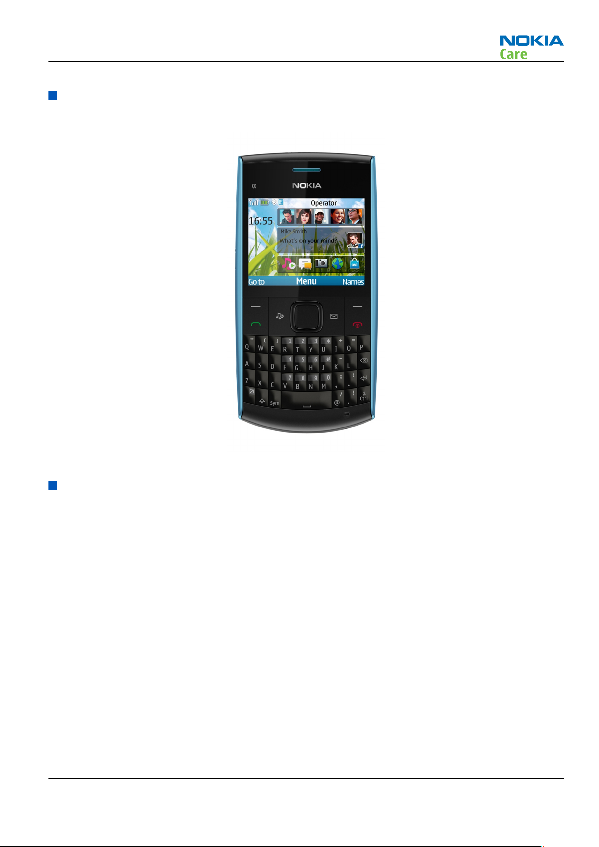
Product selection
RM-709 (X2–01) is a GSM Quad-band phone, supporting EGSM 850/900/1800/1900 bands.
Figure 1 RM-709 (X2–01) product picture
Phone features
Hardware features
•
Protocols supported: 850/900/1800/1900 (Quad-bands)
•
Broadcom HW 130 (2G)
•
Combo 128MB / 64MB memory
•
Micro USB
•
2mm classic Dynamo DC
•
3.5 mm AV connector
•
2.36’’ QVGA landscape display
•
VGA camera
•
BT 2.0
•
Stereo FM radio & RDS
•
MP3 player
•
Micro SD memory card slot
•
FOTA
•
GPRS
Issue 1 COMPANY CONFIDENTIAL Page 1 – 5
Copyright © 2010 Nokia. All rights reserved.
•
Dedicated Messaging Hard Key
•
Dedicated Music Hard Key
SW features (ISA S40 SPR9.2)
•
BT 2.1 + EDR
•
FM radio supporting RDS
•
GPRS multi-slot class 32(TX+RX 3+5 max slot6) and EGPRS MSC32(TX+RX 3+5 max slot6)
•
Java MIDP 2.1
•
Adobe Flash 3.0
•
WAP 2.0
•
MMS 1.3
•
Ovi Store 2.0.1
•
Nokia Xpress Audio messaging
•
Active Home Screen with integrated widgets
Accessories
RM-709
General information
In-box:
•
Phone: X2–01
•
Battery: BL-5C, 1020mAh
•
Charger: AC-3 (shorter) for Global (AC-8C & CA-100c for China only)
•
Headset: WH-102
For out-box accessories, please refer to enhancement list document.
Technical specifications
General specifications
Unit Dimension (mm) Weight (g) Volume (cc)
Transceiver with BL-5C
1020mAh Li Lion battery
pack
Battery Endurance
Battery Talk Time Stand-by Time
BL-5C with
1020mAh Li ion
standard battery
119.4 x 59.8 x 14.3 107.5 86.64
Best Talk Time GSMA Talk Time Best Stand-by
Time
Up to 23 hours 5 hours Up to 646.39 hours 622 hours
GSMA Stand-by
Time
Note: Variation in operation time will occur depending on SIM card, network settings and usage.
Talk time is increased by up to 30% if half rate is active and reduced by 5% if enhanced full rate is
active.
Page 1 – 6 COMPANY CONFIDENTIAL Issue 1
Copyright © 2010 Nokia. All rights reserved.

Nokia Customer Care
2 — Service Devices and
Service Concepts
Issue 1 COMPANY CONFIDENTIAL Page 2 – 1
Copyright © 2010 Nokia. All rights reserved.

RM-709
Service Devices and Service Concepts
(This page left intentionally blank.)
Page 2 – 2 COMPANY CONFIDENTIAL Issue 1
Copyright © 2010 Nokia. All rights reserved.

RM-709
Service Devices and Service Concepts
Table of Contents
Service devices....................................................................................................................................................... 2–5
Product specific devices................................................................................................................................... 2–5
MJ-299 .......................................................................................................................................................... 2–5
General devices................................................................................................................................................. 2–5
CU-4............................................................................................................................................................... 2–6
FLS-5 ............................................................................................................................................................. 2–7
FPS-21........................................................................................................................................................... 2–7
PK-1............................................................................................................................................................... 2–8
RJ-230 ........................................................................................................................................................... 2–8
SB-6............................................................................................................................................................... 2–8
SD-73 ............................................................................................................................................................ 2–8
SRT-6............................................................................................................................................................. 2–9
SS-88............................................................................................................................................................. 2–9
SS-93............................................................................................................................................................. 2–9
SX-4............................................................................................................................................................... 2–9
Cables................................................................................................................................................................. 2–9
CA-101 .......................................................................................................................................................... 2–9
PCS-1.......................................................................................................................................................... 2–10
XRS-6.......................................................................................................................................................... 2–10
Service concepts ................................................................................................................................................. 2–11
Level 1 POS flash concept ............................................................................................................................. 2–11
Level 3 concept for flashing, certificate restore and product code change ............................................ 2–12
Level 3 concept for flashing, certificate restore, product code change and EM calibration in MJ......... 2–14
Level 3 concept for BB and RF tuning.......................................................................................................... 2–16
Level 3 BT (Bluetooth) test Concept ............................................................................................................ 2–18
List of Figures
Figure 2 Level 1 POS flash concept ................................................................................................................... 2–11
Figure 3 Level 3 concept for flashing, certificate restore and product code change (option 1) ................ 2–12
Figure 4 Level 3 concept for flashing, certificate restore and product code change (option 2) ................ 2–13
Figure 5 Level 3 concept for flashing, certificate restore, product code change and EM calibration in MJ
(option 1) .................................................................................................................................................. 2–14
Figure 6 Level 3 concept for flashing, certificate restore, product code change and EM calibration in MJ
(option 2) .................................................................................................................................................. 2–15
Figure 7 Level 3 concept for BB and RF tuning (option 1).............................................................................. 2–16
Figure 8 Level 3 concept for BB and RF tuning (option 2).............................................................................. 2–17
Figure 9 Level 3 BT (Bluetooth) test Concept................................................................................................... 2–18
Issue 1 COMPANY CONFIDENTIAL Page 2 – 3
Copyright © 2010 Nokia. All rights reserved.

RM-709
Service Devices and Service Concepts
(This page left intentionally blank.)
Page 2 – 4 COMPANY CONFIDENTIAL Issue 1
Copyright © 2010 Nokia. All rights reserved.
RM-709
Service Devices and Service Concepts
Service devices
Product specific devices
The table below gives a short overview of service devices that can be used for testing, error analysis, and
repair of product RM-709. For the correct use of the service devices, and the best effort of workbench setup,
please refer to various concepts.
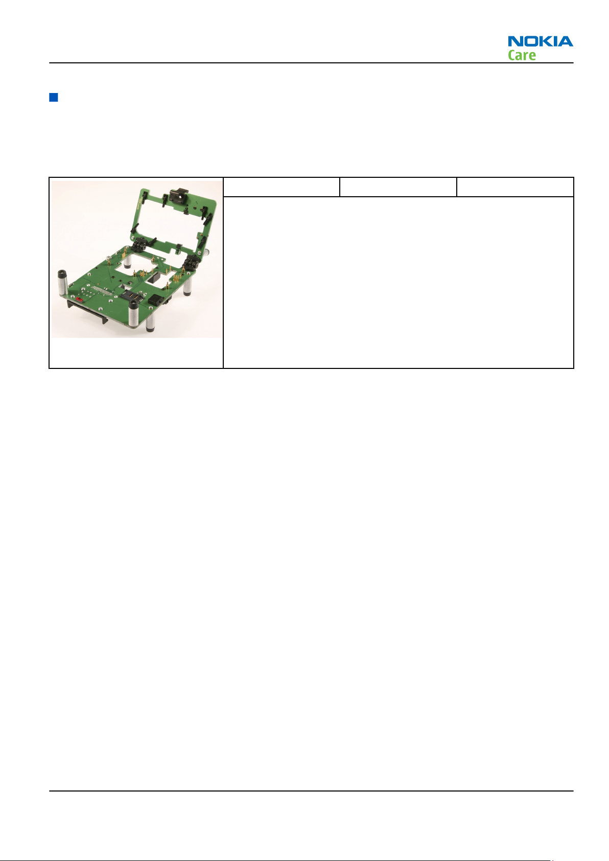
MJ-299 Module jig MJ-299 is meant for component level troubleshooting.
The jig includes an RF interface for GSM and Bluetooth. In addition, it
has the following features:
•
Provides mechanical interface with the engine module
•
Provides galvanic connection to all needed test pads in module
•
MMC interface
•
Duplicated SIM connector
•
Connector for control unit
•
Access for AV- and USB connectors
•
CA-128RS cable is used together with this jig for RF testing.
General devices
The table below gives a short overview of service devices that can be used for testing, error analysis, and
repair of product RM-709. For the correct use of the service devices, and the best effort of workbench setup,
please refer to various concepts.
Issue 1 COMPANY CONFIDENTIAL Page 2 – 5
Copyright © 2010 Nokia. All rights reserved.
RM-709
Service Devices and Service Concepts
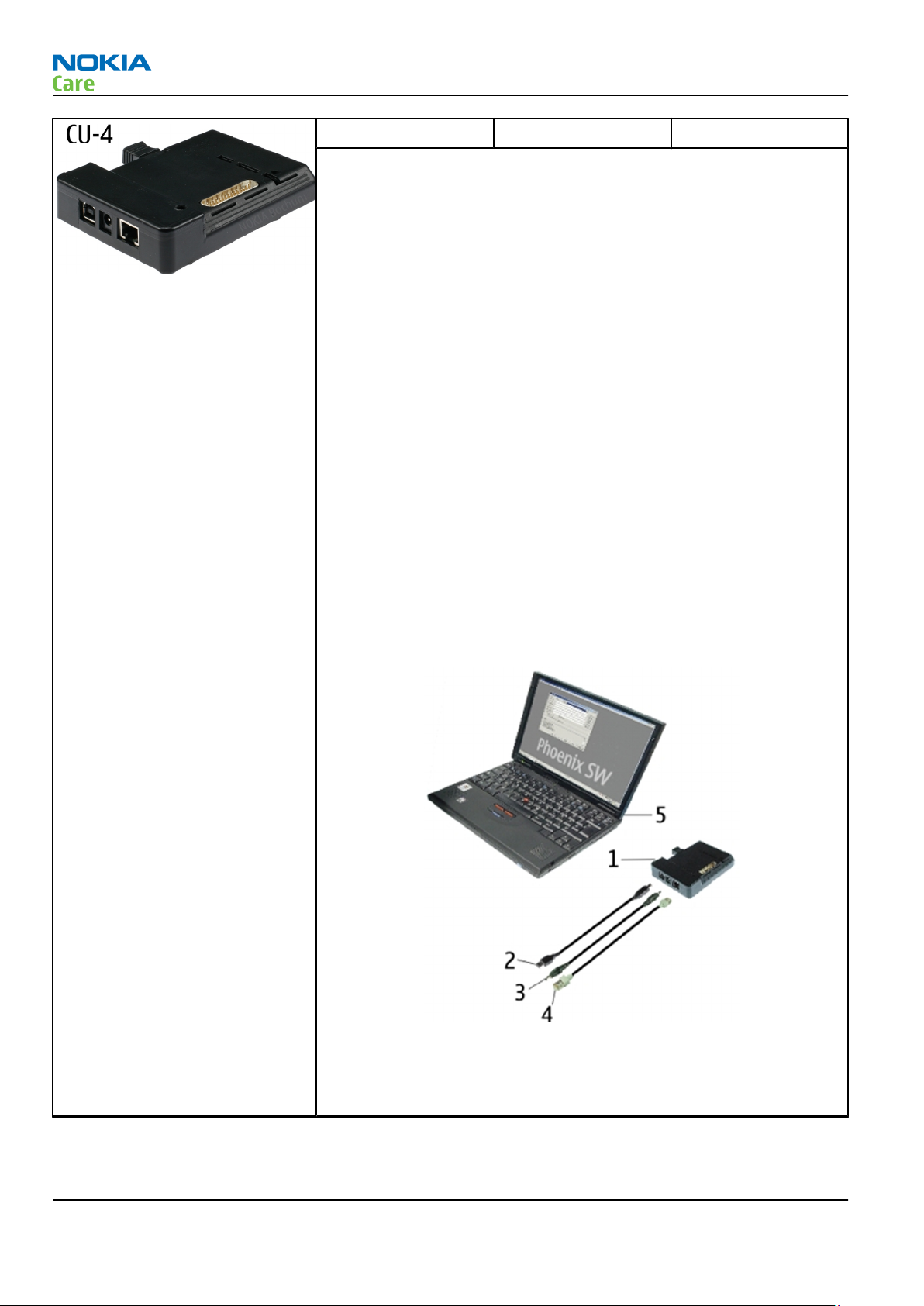
CU-4 Control unit CU-4 is a general service tool used with a module jig and/or a flash
adapter. It requires an external 12 V power supply.
The unit has the following features:
•
software controlled via USB
•
EM calibration function
•
Forwards FBUS/Flashbus traffic to/from terminal
•
Forwards USB traffic to/from terminal
•
software controlled BSI values
•
regulated VBATT voltage
•
2 x USB2.0 connector (Hub)
•
FBUS and USB connections supported
When using CU-4, note the special order of connecting cables and
other service equipment:
Instructions
1 Connect a service tool (jig, flash adapter) to CU-4.
2 Connect CU-4 to your PC with a USB cable.
3 Connect supply voltage (12 V)
4 Connect an FBUS cable (if necessary).
5 Start Phoenix service software.
Note: Phoenix enables CU-4 regulators via USB when it is
started.
Reconnecting the power supply requires a Phoenix restart.
Page 2 – 6 COMPANY CONFIDENTIAL Issue 1
Copyright © 2010 Nokia. All rights reserved.
RM-709
Service Devices and Service Concepts
FLS-5 Flash device FLS-5 is a dongle and flash device incorporated into one package,
developed specifically for POS use.
Note: FLS-5 can be used as an alternative to PK-1.
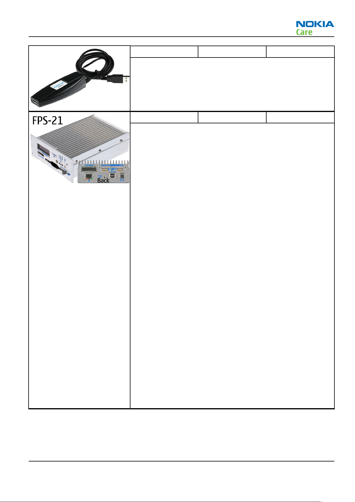
FPS-21 Flash prommer
FPS-21 sales package:
•
FPS-21 prommer
•
AC-35 power supply
•
CA-31D USB cable
FPS-21 interfaces:
Front
•
Service cable connector
Provides Flashbus, USB and VBAT connections to a mobile device.
•
SmartCard socket
A SmartCard is needed to allow DCT-4 generation mobile device
programming.
Rear
•
DC power input
For connecting the external power supply (AC-35).
•
Two USB A type ports (USB1/USB3)
Can be used, for example, for connecting external storage memory
devices or mobile devices
•
One USB B type device connector (USB2)
For connecting a PC.
•
Phone connector
Service cable connection for connecting Flashbus/FLA.
•
Ethernet RJ45 type socket (LAN)
For connecting the FPS-21 to LAN.
Inside
•
Four SD card memory slots
For internal storage memory.
Note: In order to access the SD memory card slots inside
FPS-21, the prommer needs to be opened by removing the
front panel, rear panel and heatsink from the prommer body.
Issue 1 COMPANY CONFIDENTIAL Page 2 – 7
Copyright © 2010 Nokia. All rights reserved.
RM-709
Service Devices and Service Concepts
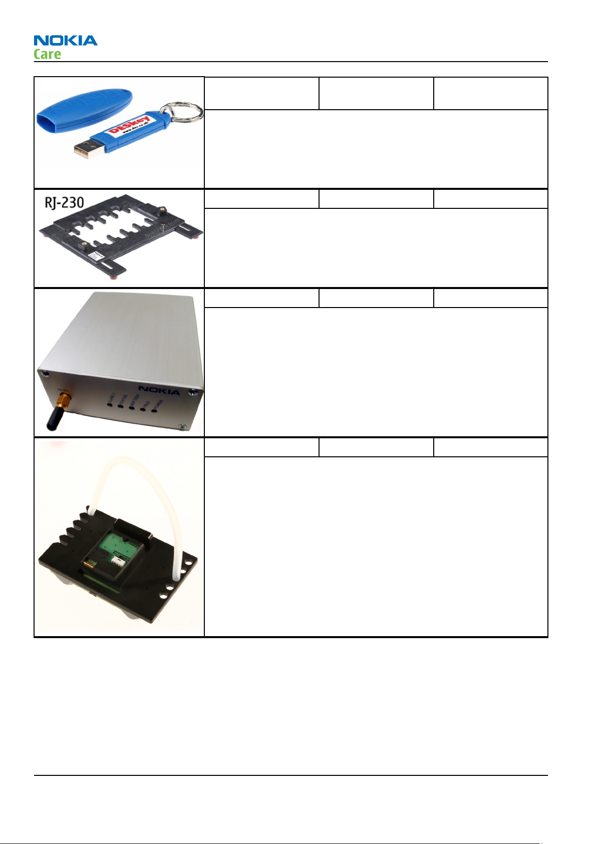
PK-1 Software protection
key
PK-1 is a hardware protection key with a USB interface. It has the same
functionality as the PKD-1 series dongle.
PK-1 is meant for use with a PC that does not have a series interface.
To use this USB dongle for security service functions please register
the dongle in the same way as the PKD-1 series dongle.
RJ-230 Common jig
RJ-230 is a jig used for soldering and as a rework jig for the engine
module.
SB-6 Bluetooth tester The SB-6 test box is a generic device to perform Bluetooth bit error
rate testing and doing cordless FBUS connection via Bluetooth.
SD-73 Dummy battery SD-73 is designed to support mass SW flashing which enables local
mode while connecting the phone.
Page 2 – 8 COMPANY CONFIDENTIAL Issue 1
Copyright © 2010 Nokia. All rights reserved.
RM-709
Service Devices and Service Concepts
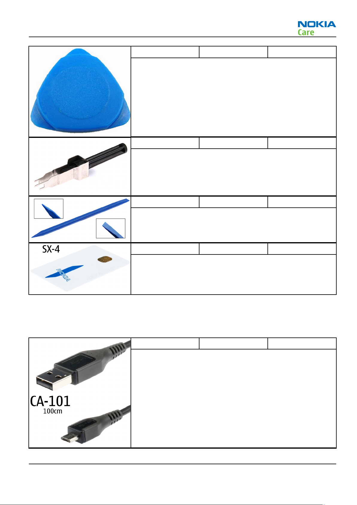
SRT-6 Opening tool SRT-6 is used to open phone covers.
Note: The SRT-6 is included in the Nokia Standard Toolkit.
SS-88 Camera removal tool The camera removal tool SS-88 is used to remove/attach the camera
module from/to the camera socket of the phone PWB.
SS-93 Blue stick tool SS-93 is used for general disassembly and assembly tasks.
SX-4 Smart card SX-4 is a BB5 security device used to protect critical features in tuning
and testing.
SX-4 is also needed together with FPS-21 when DCT-4 phones are
flashed.
Cables
The table below gives a short overview of service devices that can be used for testing, error analysis, and
repair of product RM-709. For the correct use of the service devices, and the best effort of workbench setup,
please refer to various concepts.
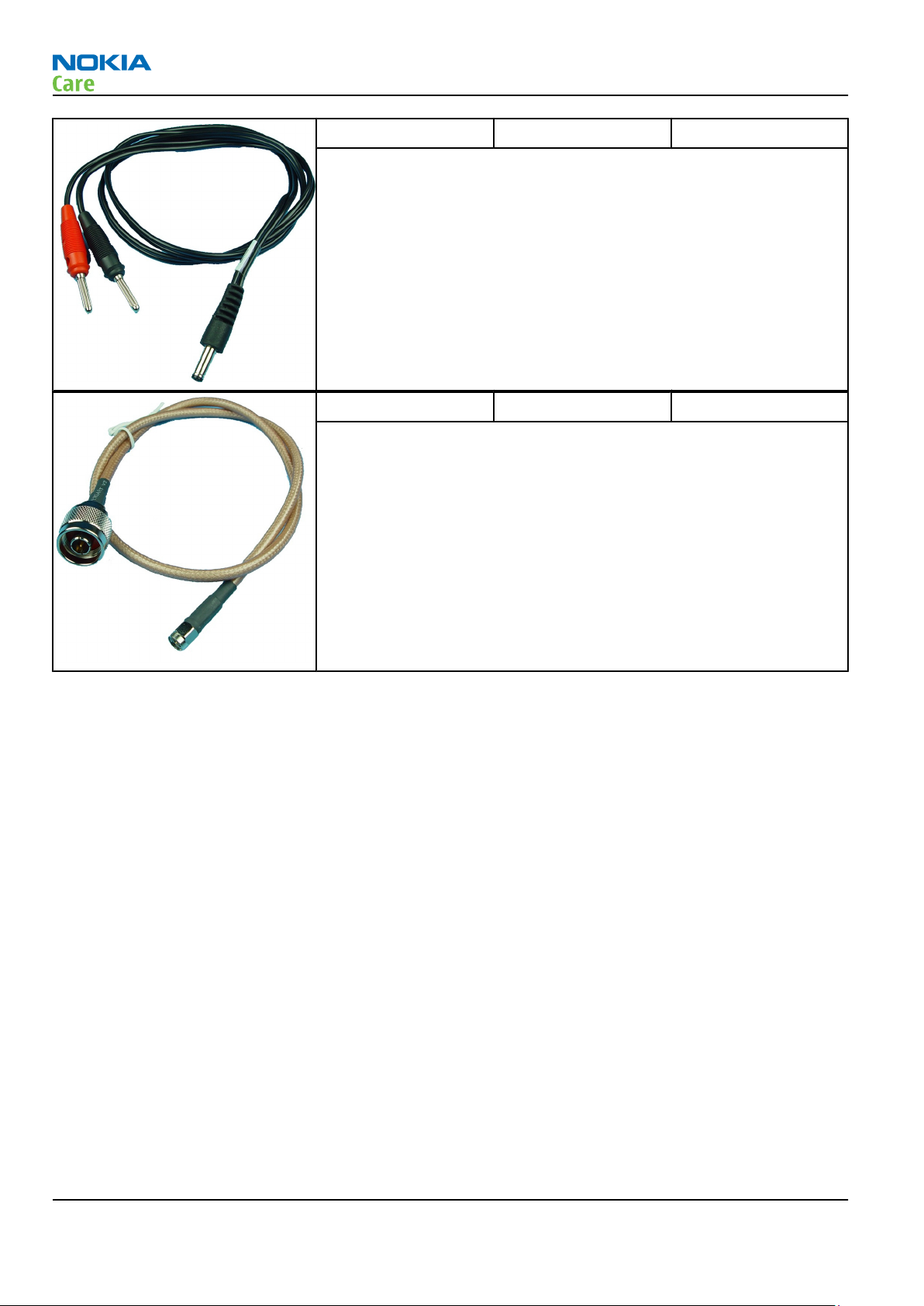
CA-101 Micro USB cable The CA-101 is a USB-to-microUSB data cable that allows connections
between the PC and the phone.
Issue 1 COMPANY CONFIDENTIAL Page 2 – 9
Copyright © 2010 Nokia. All rights reserved.
RM-709
Service Devices and Service Concepts
PCS-1 Power cable The PCS-1 power cable (DC) is used with a docking station, a module
jig or a control unit to supply a controlled voltage.
XRS-6 RF cable The RF cable is used to connect, for example, a module repair jig to
the RF measurement equipment.
SMA to N-Connector approximately 610 mm.
Attenuation for:
•
GSM850/900: 0.3+-0.1 dB
•
GSM1800/1900: 0.5+-0.1 dB
Page 2 – 10 COMPANY CONFIDENTIAL Issue 1
Copyright © 2010 Nokia. All rights reserved.
RM-709
Service Devices and Service Concepts
Service concepts
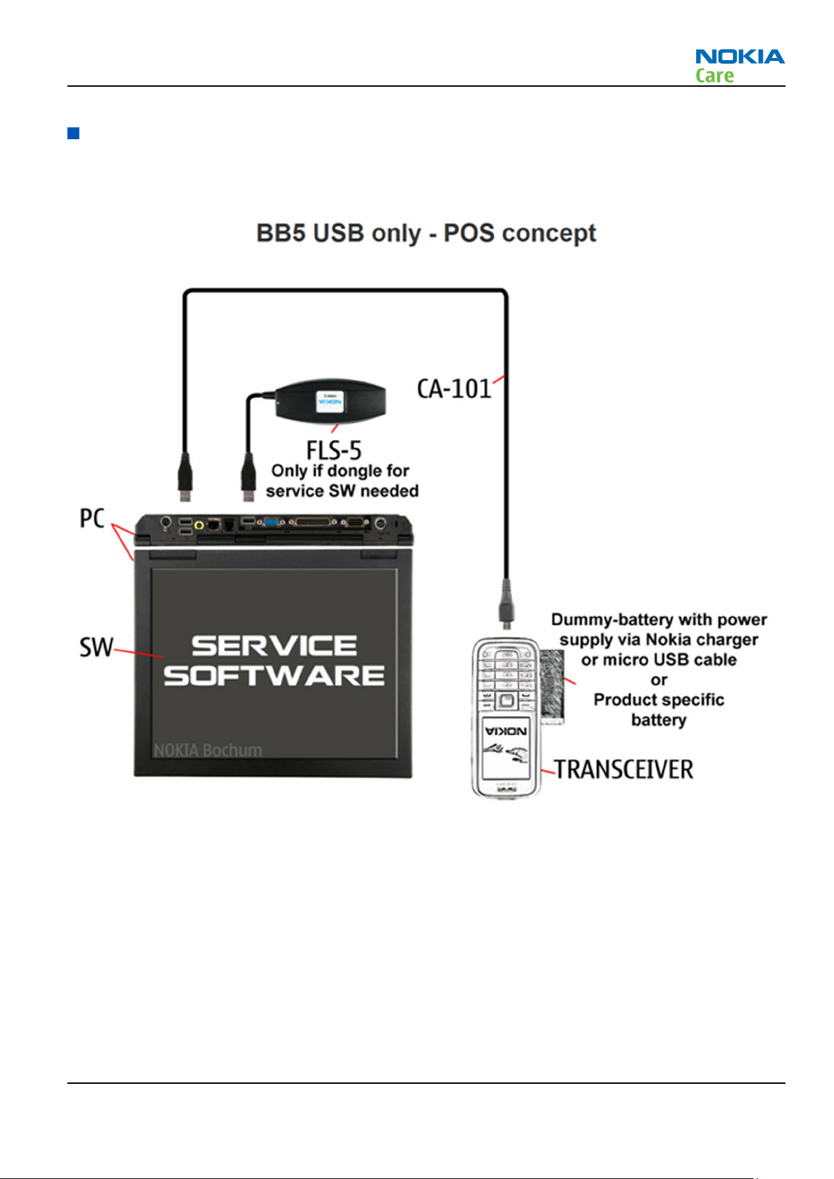
Level 1 POS flash concept
Figure 2 Level 1 POS flash concept
Issue 1 COMPANY CONFIDENTIAL Page 2 – 11
Copyright © 2010 Nokia. All rights reserved.
Service Devices and Service Concepts
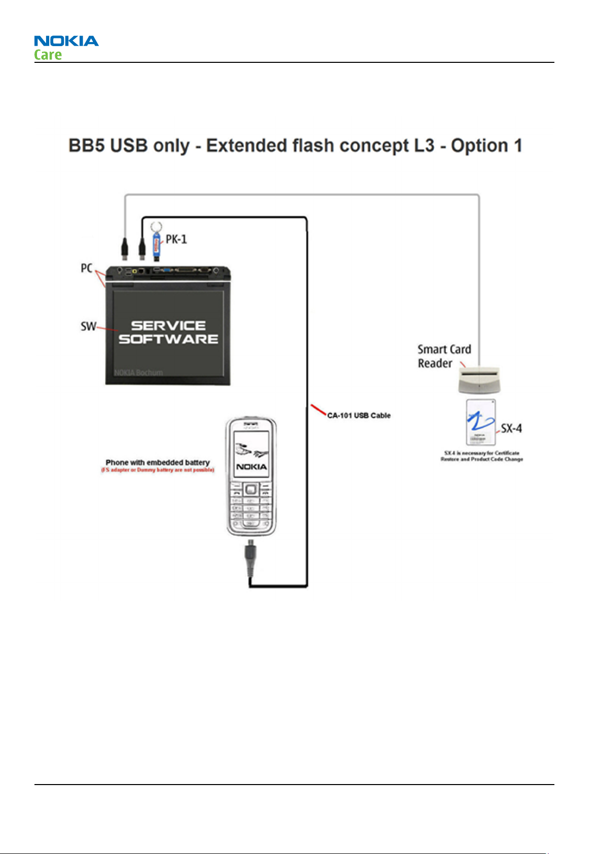
Level 3 concept for flashing, certificate restore and product code change
RM-709
Figure 3 Level 3 concept for flashing, certificate restore and product code change (option 1)
Page 2 – 12 COMPANY CONFIDENTIAL Issue 1
Copyright © 2010 Nokia. All rights reserved.
Loading...