


ELECTRIC EXPLOSION PROOF VACUUM CLEANER MODEL MODELO DE ASPIRADOR ELÉCTRICO A PRUEBA DE EXPLOSIÓN ASPIRATEUR ANTI-DÉFLAGRANT ÉLECTRIQUE MODÈLE
118EXP
(dry use only) (sólo uso en seco) (utilisation sèc he seulement)
INSTRUCTIONS FOR USE
INSTRUCCIONES DE USO
INSTRUCTIONS D'UTILISATION
For Use in Class I - Group D
Class II - Group E, F and G Hazardous Locations
Para la utilización en lugares peligrosos de clase I - grupo D, Clase II - grupo E, F y G
Pour utilisation dans les emplacements
dangereux de Classe I - Groupe D, Classe II - Groupes E, F et G
CAUTION: TO INSURE THE SAFE USE OF THIS VACUUM MACHINE, OPERATORS MUST READ AND UNDERSTAND THE FOLLOWING INSTRUCTIONS BEFORE ATTEMPTING TO PLACE THE MACHINE IN SERVICE
ATENCIÓN: PARA GARANTIZAR LA UTILIZACIÓN SEGURA DE ESTE ASPIRADOR, LOS OPERADORES DEBEN LEER Y COMPRENDER LAS SIGUIENTES INSTRUCCIONES ANTES DE INTENTAR PONER LA MÁQUINA EN MARCHA
MISE EN GARDE: AFIN D'ASSURER UNE UTILISATION SECURITAIRE DE CET ASPIRATEUR, LES OPERATEURS DOIVENT LIRE ET COMPRENDRE LES
INSTRUCTIONS QUI SUIVENT AVANT LA MISE EN MARCHE DE CETTE MACHINE
C309 02/2010
Nilfisk-Advance America, Inc., 300 Technology Drive, Malvern, Pa 19355, (610) 647-6420

INSTRUCTIONS FOR USE |
PAGE 1 |
English
INSTRUCTIONS FOR USE |
PAGE 2 |
Contents |
Page |
Test For Ground Continuity …………………………………………………………………………. |
2 |
Preparing the Machine for Dry Recovery …………………………………………………………. |
3 |
Making Adjustments to Container Gaskets ……………………………………………………… |
3 |
Using the Vacuum………………………………………………………………………………………. |
4 |
Using the Vacuum/ Turning the Machine On/Off…………………………………………………….. |
5 |
Using the Vacuum/ Cleaning the Main Filter…………………………………………………………. |
5 |
Using the Vacuum/ Emptying the Container…………………………………………………………. |
5 |
Replacing Parts ………………………………………………………………………………………… |
6 |
Replacing Parts/ Replacing the HEPA Filter ……………………………………………………….. |
6 |
Replacing Parts/ Replacing Main filter ……………………………………………………………… |
6 |
Replacing Parts/ Replacing the optional (upstream) HEPA Filter ………………………………… |
7 |
Parts Explosion ………………………………………………………………………………………… |
8 |
Parts Explosion/ Container unit ……………………………………………………………………….. |
8 |
Parts Explosion/ Suction unit …………………………………………………………………………. |
9 |
Dimensions ………………………………………………………………………………………………. |
10 |
Wirings Diagrams ……………………………………………………………………………………… |
11 |
Applications …………………………………………………………………………………………….. |
12 |
Grounding Instructions ……………………………………………………………………………….. |
12 |
Tools and Attachments ………………………………………………………………………………. |
12 |
Warranty ………………………………………………………………………………………………… |
13 |
Accessories ………………………………………………………………………………………………… |
14 |
PLEASE READ THESE INSTRUCTIONS COMPLETELY BEFORE USING THE MACHINE
CAUTION: THE OPERATOR SHOULD TEST THE VACUUM MACHINE FOR GROUND CONTINUITY BEFORE EACH USE
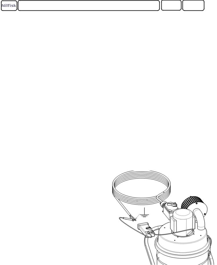
TEST FOR GROUND CONTINUITY (Ul 1213 par. 22)
1.Make sure that the grounding path between the terminal for connection of the grounding conductor of the power cord and parts of the Vacuum is assured.
2.Check the ground continuity with an appropriate continuity tester.
3.The resistance of the grounding continuity path shall not exceed 0.1 ohm.
WARNING: If unacceptable results are recorded, DO NOT OPERATE THE CLEANER. Using the tester, check for continuity between each connection of the vacuum
cleaner (example: tool to wand, wand to hose, hose to machine, etc) If the problem can not be corrected refer the unit to an AUTHORIZED SERVICE CENTER ONLY.
INSTRUCTIONS FOR USE |
PAGE 3 |
PREPARING THE MACHINE FOR DRY RECOVERY
1.Release latches and remove power-head from recovery tank.
2.Insure that the static dissipating, polyester felt filter is properly mounted in the recovery tank. If not, refer to the instructions for “Replacing the Main Filter” (page 6).
3.Place the power-head back on the recovery tank and fasten latches.
1
4.Attach the static dissipating hose to the suction
inlet on the recovery tank and attach the desired tool to the hose.
5.Conduct a ground continuity check before operating (Figure 1).
6.Operate this machine only on properly grounded electrical outlets.
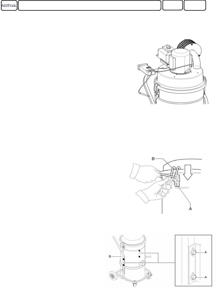
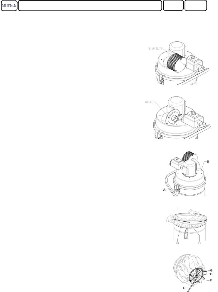
MAKING ADJUSTMENTS TO CONTAINER GASKETS
If you suspect the gasket between the motor head and the filter chamber is not sealing properly:
1.Loosen latch screws "A" and slide latch downward.
2.Tighten latch screws.
3.Turn on the unit and inspect the seal between the motor head and filter chamber.
4.Replace the gasket if the seal continues to leak.
If you suspect the gasket between the filter chamber and the collection can is not sealing properly:
1.Loosen the screws "A" that lock filter chamber "B" against the vacuum structure.
2.Lower filter chamber "B" slightly and retighten screws "A".
3.Turn on the unit and inspect the seal between the filter chamber and the collection can.
4.Replace the gasket if the seal continues to leak.
INSTRUCTIONS FOR USE |
PAGE 4 |
USING THE VACUUM
CAUTION: OPERATORS SHOULD TEST THE VACUUM MACHINE FOR GROUND CONTINUITY BEFORE EACH USE
WARNING: A HEPA FILTER MUST BE INSTALLED IN THE VACUUM MACHINE
WHILE WORKING WITH HAZARDOUS MATERIAL FAILURE TO DO SO WILL EXPOSE PEOPLE IN THE WORK AREA AND OTHERS TO HAZARDOUS MATERIALS WHICH IS A SERIOUS HEALTH RISK.
EMPTYING: IF THIS VACUUM CLEANER IS USED TO COLLECT HAZARDOUS MATERIALS, DO NOT ATTEMPT TO OPEN OR EMPTY ITS CONTENTS WITHOUT PERSONAL PROTECTIVE CLOTHING AND RESPIRATORY PROTECTION. ALL DISPOSED FILTERS, BAGS, DEBRIS SHOULD BE TREATED AS A HAZARDOUS SUBSTANCE AND MUST BE DISPOSED OF IN ACCORDANCE WITH ALL FEDERAL, STATE
AND LOCAL REGULATIONS
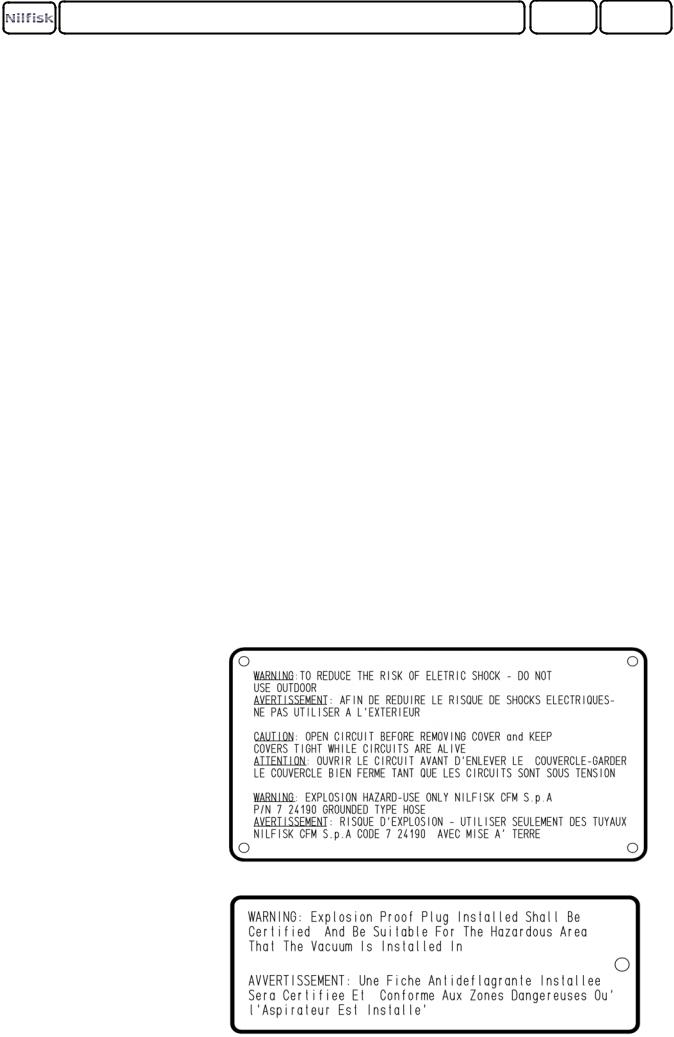
WARNING: EXPLOSION HAZARD - USE ONLY NILFISK CFM P/N 7 24190 GROUNDED TYPE HOSE.
THIS EQUIPMENT IS CERTIFIED FOR EXPLOSION-PROOF OPERATION,ONLY IF USED WITH SUPPLIED OR RECOMMENDED HOSE AND TOOLS. ANY ALTERATION TO THIS EQUIPMENT BY A THIRD PARTY WILL NULLIFY ITS CERTIFICATION.
WARNING LABELS :
-ON THE VACUUM CLEANER
-ON THE POWERCORD
INSTRUCTIONS FOR USE |
PAGE 5 |
USING THE VACUUM
TURNING THE MACHINE ON/OFF |
1 |
1.Plug the vacuum cleaner into an approved power source.
2.Turn on the vacuum cleaner by rotating the main switch to the “ON” position (Figure 1).
3.Turn off the vacuum cleaner by rotating the main switch back to the “OFF” position (Figure 1).
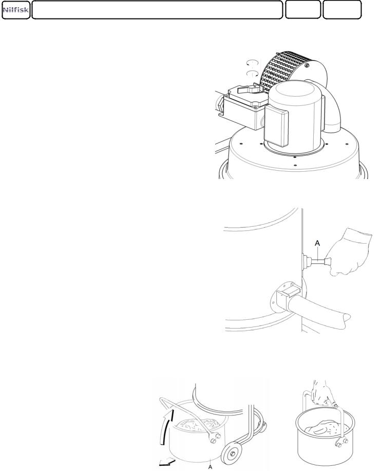
CLEANING THE MAIN FILTER
If the performance of the vacuum cleaner decreases during use, it may be necessary to clean the primary filter:
1. |
Turn off the vacuum and disconnect the vacuum from |
2 |
|
|
its power source. |
|
|
2. |
Actuate the filter shaker "A" (Figure 2) by raising |
|
|
|
and lowering the lever. |
|
|
3. |
Repeat this several times to shake the dirt from the |
|
|
|
primary filter. |
|
|
4. |
Wait a few minutes for the dust to settle at the bottom |
|
|
|
of the container. |
|
|
5. |
Empty the container |
|
|
EMPTYING THE CONTAINER |
|
|
|
1. |
Turn off the vacuum and disconnect the |
3 |
4 |
|
vacuum from its power source. |
||
2.Detach container "A" (Figure 3) by lifting the handle.
3.Slide the container out from the machine
and carry the container by the handle (figure 4).
INSTRUCTIONS FOR USE |
PAGE 6 |
REPLACING PARTS
REPLACING THE HEPA FILTER
1
1.Remove the wing nuts that secure the HEPA screen (Figure 1).
2.Pull off the screen surrounding the three posts.
3.Remove old HEPA cartridge by carefully pulling cartridge through the posts.
4.Remove the old foam gasket from around the exhaust port.
5.Place a new foam gasket around the exhaust port (Figure 2).
2
6.Carefully install new HEPA cartridge against the foam gasket with the label facing out.
7.Reinstall the screen around the posts.
8.Tighten the wing nuts.
REPLACING THE MAIN FILTER
1. Release the latches "A" and remove the Motor Head "B" (Figure 3). |
3 |
2. Raise one side of the filter and reach down under the filter with one hand to remove split pin "D". This will release the filter shaker lever "E" from the filter ring "F" (Figure 5).
3.Lift up of the filter and cut the ties (G) that attach the filter to the ring "F"(Figure 5).
4.Unscrew clamp "H" and remove the upper ring "I" (Figure 4).
5.Mount the upper ring "I" onto the new filter and secure
the ring in place with clamp "H" (Figure 4). |
4 |
6.Secure the Filter "C" to the ring "F" using the ties "G" supplied in the new filter kit (Figure 5).
7.Place the new filter assembly inside the filter chamber and reconnect the assembly using the split pin "D" (Figure 5).
8. Mount the motor head "B" onto the machine and secure |
5 |
in place with the latches "A" (Figure 3). |
|
9.Dispose of the old filter in accordance with all federal, state and local regulations.
INSTRUCTION FOR USE |
PAGE 7 |
REPLACING PARTS
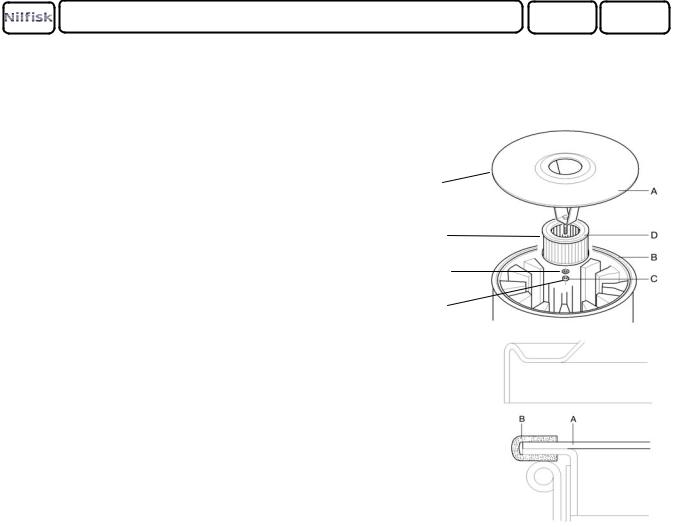
REPLACING THE OPTIONAL (UPSTREAM) HEPA FILTER
1. Release the latches and remove the motor head.
1
2.Separate disc "A" from gasket "B" and remove disc/filter assembly from the vacuum machine.
|
|
2 |
3. |
Loosen nut "C" and remove the HEPA filter "D". |
|
|
|
3 |
4. |
Fit a new HEPA Filter onto Disc"A" and tighten |
|
|
in place. |
4 |
5.Slide the disc with new filter into gasket "B".
6.Replace the motor head onto the vacuum machine.
7.Dispose of the old filter in accordance with all federal, state and local regulations.
POS. |
N^CODE |
Q |
DESCRIPTION |
POS. |
N^CODE |
Q |
DESCRIPTION |
1 |
8 33323G |
1 |
DISC |
3 |
BR010X |
1 |
WASHER |
2 |
8 17262 |
1 |
HEPA FILTER |
4 |
BN10X |
1 |
NUT |
INSTRUCTION FOR USE |
PAGE 8 |
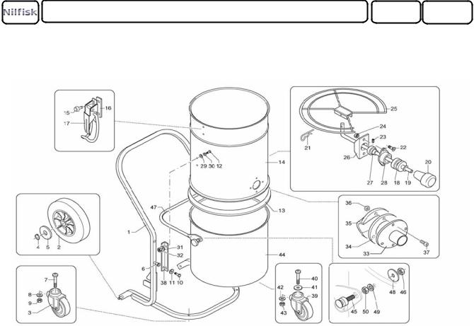
PARTS EXPLOSION
CONTAINER UNIT
ACT DE |
N^CODE |
Q |
DESCRIPTION |
POS. |
N^CODE |
Q |
DESCRIPTION |
1 |
8 36359 |
1 |
CAR |
26 |
8 15130 |
1 |
SUPPORT |
2 |
8 40261 |
2 |
WHEEL |
27 |
8 38047 |
1 |
ARTICULATION |
3 |
8 40910 |
2 |
WHEEL |
28 |
8 15131 |
1 |
BELOWS HOLDER |
4 |
BSEE15G |
2 |
CLIP |
29 |
BR00824X |
4 |
WASHER |
5 |
BRO15ZB |
1 |
WASHER |
30 |
BRODO8X |
4 |
WASHER |
6 |
8 38059 |
4 |
RIVET |
31 |
BROO8X |
4 |
WASHER |
7 |
BVTBCE0840ZB |
2 |
SCREW |
32 |
BDNO8X |
4 |
NUT |
8 |
BRO08ZB |
2 |
WASHER |
33 |
8 32086 |
1 |
FILLER |
9 |
BDABO8ZB |
2 |
NUT |
34 |
8 17005 |
1 |
SEAL |
10 |
BVTEO62OZB |
4 |
SCREW |
35 |
8 32314 |
1 |
DEFLECTOR |
11 |
BROO618ZB |
4 |
WASHER |
36 |
BDNO5X |
4 |
NUT |
12 |
BVTBCEO816X |
4 |
SCREW |
37 |
BVTBCEO525X |
4 |
SCREW |
13 |
8 17226 |
1 |
SILICON SEAL |
38 |
8 18970 |
2 |
BRACKET |
14 |
8 11110 |
1 |
CHAMBER |
39 |
8 40402 |
3 |
WHEEL |
15 |
BVTEZO6O8X |
4 |
SCREW |
40 |
BVTBCEO82OX |
3 |
SCREW |
16 |
8 18010 |
2 |
PLAQUE |
41 |
BR00832X |
3 |
WASHER |
17 |
8 36030 |
2 |
LOCK |
42 |
BROO8ZB |
3 |
WASHER |
18 |
8 40393 |
1 |
BELLOWS |
43 |
BDAO8ZB |
3 |
NUT |
19 |
8 33221 |
1 |
ROD-INOX |
44 |
8 30337 |
1 |
CONTAINER |
20 |
8 40373 |
1 |
HANDGRIP |
45 |
8 14579 |
2 |
PIN |
21 |
8 38018 |
1 |
COTTER PIN |
46 |
BDAO8X |
2 |
NUT |
22 |
BVTBCO616X |
1 |
SCREW |
47 |
8 18971 |
1 |
HANDLE |
23 |
BVSTCECO4O6X |
1 |
DOWEL |
48 |
BR00832X |
2 |
WASHER |
24 |
BDAO6X |
1 |
NUT |
49 |
BROO8X |
2 |
WASHER |
25 |
8 33174 |
1 |
RING |
50 |
BDNO8X |
2 |
NUT |

INSTRUCTION FOR USE |
PAGE 9 |
PARTS EXPLOSION
SUCTION UNIT
POS. |
N^CODE |
Q |
DESCRIPTION |
POS. |
N^CODE |
Q |
DESCRIPTION |
1 |
8 17125 |
1 |
GASKET |
13 |
8 12403 |
1 |
CAP |
2 |
8 18078 |
1 |
STOP |
14 |
8 17006 |
3 |
GASKET |
3 |
8 15009 |
1 |
RING |
15 |
BDN06X |
8 |
NUT |
4 |
8 17140 |
1 |
FILTER |
16 |
8 391241 |
1 |
CABLE-PRESS |
5 |
8 18980 |
2 |
GROUNDING TAB |
17 |
8 391242 |
1 |
CONNECTOR |
6 |
8 38073 |
3 |
WING NUTS |
18 |
8 391240 |
1 |
SWITCH |
7 |
8 38072 |
3 |
POSTS |
19 |
8 391243 |
1 |
CONNECTOR |
8 |
8 31698 |
1 |
SCREEN |
20 |
8 54017 |
1 |
MOTOR |
9 |
01727631 |
1 |
HEPA FILTER |
21 |
8 17804 |
1 |
GASKET |
10 |
8 35130 |
1 |
MOTOR FIXING DEVICE |
22 |
8 13066 |
1 |
MESH |
11 |
8 14623 |
4 |
STUD |
23 |
8 39669 |
1 |
EARTH CABLE |
|
|
|
|
|
|
|
|
12 |
8 17124 |
1 |
GASKET |
24 |
8 391244 |
1 |
CABLE |
|
|
|
|
|
|
|
|
INSTRUCTION FOR USE |
PAGE 10 |
DIMENSIONS
INSTRUCTION FOR USE |
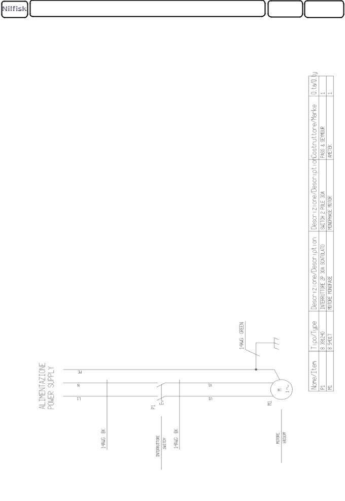
PAGE 11 |
WIRING DIAGRAMS

INSTRUCTION FOR USE |
PAGE 12 |
APPLICATIONS
The electric motors used in the Nilfisk Explosion Proof vacuum Cleaner model 118EXP have been listed by Underwriters Laboratories Inc. in guide PTDR file E25653, for use in the following hazardous locations classifications:
Class l/Group D |
Atmospheres containing: gasoline, petroleum, naphtha, benzine, butalie, propane, alcohol, |
|
acetone, benzol, lacquer solvent vapors or natural gas. |
Warning: Do not use this or any other Nilfisk CFM vacuum for the purposes of cleaning or extracting fuel residues from airplanes or ships.
Class ll/Group E |
Atmospheres containing: metal dust |
Class ll/Group F |
Atmospheres containing: carbon, black coal or coke dust. |
Class ll/Group G |
Atmospheres containing: flour, starch or grain dust. |
NOTE: The motors used in this vacuum cleaner are designed for use in commercial and industrial vacuum equipment which employs filters to remove dirt from the airstream before reaching the motor’s vacuum fans. Do not operate the vacuum cleaner without the proper filter system installed.
GROUNDING INSTRUCTIONS
This vacuum cleaner must be connected to an earth ground source. Cord plug installed by customer,shall be suitable for the hazardous locations area that vacuum is installed in. If the vacuum cleaner should malfunction or break down, grounding provides a path of least resistance for electric current to reduce the risk of electrical shock. This vacuum cleaner must be properly installed and grounded in accordance with all local codes and ordinances.
DANGER: Improper connection of the equipment-grounding conductor can result in a risk of electric shock.
Check with a qualified electrician or service person if you are in doubt as to whether the outlet is properly grounded. Use only with certified explosion-proof plugs and outlets.
TOOLS AND ATTACHMENTS
WARNING: EXPLOSION HAZARD - USE ONLY NILFISK CFM P/N 7 24190 GROUNDED TYPE HOSE.
This equipment is only certified for explosion-proof operation if it is equipped with the proper conductive hose and tools. Any alteration to this equipment by a third party will nullify its certification.
 Loading...