

Page 1

Series 244 Actuators Product Information
Models 244.11, 244.12, 244.20, 244.21, 244.22, 244.23,
244.31, 244.41, 244.51
011-551-304 G be certain.
Page 2

© 2013 MTS Systems Corporation. All rights reserved.
Original Instructions (English): 011-551-304 G
Trademark Information
MTS, be certain., Bionix, ElastomerExpress, FlatTrac, FlexTest, Just In Case, LevelPlus, MTS Criterion, MTS
EM Extend, MTS Insight, MTS Landmark, RPC, ServoSensor, SWIFT, Temposonics, TestWare, TestWorks are
registered trademarks of MTS Systems Corporation within the United States. Acumen, Advantage, Aero ST,
Aero-90, AeroPro, Criterion, CRPC, Echo, Flat-Trac, Landmark, MAST, MicroProfiler, MPT, MTS Acumen, MTS
Echo, MTS Fundamentals, MTS TestSuite, ReNew, SilentFlo, TempoGuard, TestLine, and Tytron are trademarks
of MTS Systems Corporation within the United States. These trademarks may be registered in other countries.
All other trademarks are property of their respective owners.
Proprietary Software
Software use and license is governed by the MTS End User License Agreement which defines all rights retained
by MTS and granted to the End User. All Software is proprietary, confidential, and owned by MTS Systems
Corporation and cannot be copied, reproduced, disassembled, decompiled, reverse engineered, or distributed
without express written consent of MTS.
Software Verification and Validation
MTS software is developed using established quality practices in accordance with the requirements detailed in
the ISO 9001 standards. Because MTS-authored software is delivered in binary format, it is not user accessible.
This software will not change over time. Many releases are written to be backwards compatible, creating another
form of verification. The status and validity of the MTS operating software is also checked during system verification
and routine calibration of MTS hardware. These controlled calibration processes compare the final test results
after statistical analysis against the predicted response of the calibration standards. With these established
methods, MTS assures its customers that MTS products meet exacting quality standards when initially installed
and will continue to perform as intended over time.
Manual Part Number—Publication Date—Release
011-551-304 G—October 2013
011-551-304 F—September 2008
011-551-304 E—July 2008
011-551-304 D—June 2002
011-551-304 C—May 2000
011-551-304 B—November 1998
011-551-304 A—September 1996
011-551-303 G—June 1994
011-551-303 F—July 1993
011-551-303 E—November 1991
011-551-303 D—June 1990
011-551-303 C—February 1989
011-551-303 B—February 1988
011-551-303 A—June 1987
011-551-302 A—September 1984
011-551-301 A—August 1983
011-551-300 A—December 1982
Page 3

Contents
Technical Support 5
Preface 9
Introduction 13
How to Get Technical Support.................................................................................................................5
Before You Contact MTS.........................................................................................................................5
If You Contact MTS by Phone.................................................................................................................7
Problem Submittal Form in MTS Manuals..............................................................................................8
Before You Begin.....................................................................................................................................9
Documentation Conventions....................................................................................................................9
About the 244 Series Actuator...............................................................................................................14
What You Need to Know.......................................................................................................................14
Component Identication.......................................................................................................................15
Functional Description...........................................................................................................................17
About Actuator Mounting..........................................................................................................18
Actuator Operation.....................................................................................................................19
LVDT Operation.........................................................................................................................19
Specications.........................................................................................................................................20
Force Ratings..............................................................................................................................20
Environmental and Hydraulic Fluid Recommendations........................................................................21
Dimensions.............................................................................................................................................23
LVDT Housing Specications...............................................................................................................26
Pedestal Base Specications..................................................................................................................29
Safety 31
General Safety Practices: Hydraulic Power Units and Hydraulic Service Manifolds............................32
Safety Practices Before Operating the System.......................................................................................33
Safety Practices While Operating the System .......................................................................................37
Hazard Placard Placement......................................................................................................................38
Labels And Icons........................................................................................................................39
Warning Label................................................................................................................39
Warning Label................................................................................................................39
Caution Label.................................................................................................................40
Attached Mass Warning Label.......................................................................................40
Hydraulic Actuator ID Tag.............................................................................................41
Hydraulic Actuator ID Tag.............................................................................................41
Pressure Icon Label........................................................................................................42
Pressure Rating Label.....................................................................................................42
Lift Hole Thread Size.....................................................................................................43
Series 244 Actuators Product Information 3
Page 4

Installation 45
About Installation...................................................................................................................................46
Load Units..............................................................................................................................................46
Installing a Fixture to the Actuator.........................................................................................................47
Mounting Bolt Specications.....................................................................................................48
Spiral Washers........................................................................................................................................50
Installing Fixtures with Spiral Washers..................................................................................................51
Multiple Fixtures With Different Ratings..................................................................................51
Removing Fixtures with Spiral Washers................................................................................................53
Multiple Fixtures With Different Ratings..................................................................................54
LVDT Cable Connection........................................................................................................................54
Hydraulic Connections...........................................................................................................................55
Operation 57
About Operation.....................................................................................................................................58
Actuator ID.............................................................................................................................................58
Operating Considerations.......................................................................................................................58
Sideload Forces..........................................................................................................................59
Sideload Calculation Procedure.............................................................................................................59
Sample Calculation.................................................................................................................................62
Maintenance 65
Maintenance Recommendations.............................................................................................................66
4 Series 244 Actuators Product Information
Page 5

Technical Support
How to Get Technical Support
Start with your manuals
The manuals supplied by MTS provide most of the information you need to use and maintain your equipment.
If your equipment includes software, look for online help and README files that contain additional product
information.
Technical support methods
MTS provides a full range of support services after your system is installed. If you have any questions about
a system or product, contact Technical Support in one of the following ways.
Web site
Outside the U.S.
For technical support outside the United States, contact your local sales and service office. For a list of
worldwide sales and service locations and contact information, use the Global MTS link at the MTS web site:
www.mts.com > Global Presence > Choose a Region
www.mts.com > Contact Us (upper-right corner) > In the Subject field, choose
To escalate a problem; Problem Submittal Form
Worldwide: tech.support@mts.comE-mail
Europe: techsupport.europe@mts.com
Worldwide: 1 800 328 2255 - toll free in U.S.; +1 952 937 4000 - outside U.S.Telephone
Europe: +800 81002 222, International toll free in Europe
Before You Contact MTS
MTS can help you more efficiently if you have the following information available when you contact us for
support.
Know your site number and system number
The site number contains your company number and identifies your equipment type (such as material testing
or simulation). The number is typically written on a label on your equipment before the system leaves MTS.
If you do not know your MTS site number, contact your sales engineer.
Example site number: 571167
Series 244 Actuators Product Information 5
Page 6

When you have more than one MTS system, the system job number identifies your system. You can find
your job number in your order paperwork.
Example system number: US1.42460
Know information from prior technical assistance
If you have contacted MTS about this problem before, we can recall your file based on the:
• MTS notification number
• Name of the person who helped you
Identify the problem
Describe the problem and know the answers to the following questions:
• How long and how often has the problem occurred?
• Can you reproduce the problem?
• Were any hardware or software changes made to the system before the problem started?
• What are the equipment model numbers?
• What is the controller model (if applicable)?
• What is the system configuration?
Know relevant computer information
For a computer problem, have the following information available:
• Manufacturer’s name and model number
• Operating software type and service patch information
• Amount of system memory
• Amount of free space on the hard drive where the application resides
• Current status of hard-drive fragmentation
• Connection status to a corporate network
Know relevant software information
For software application problems, have the following information available:
• The software application’s name, version number, build number, and (if available) software patch number.
This information can typically be found in the About selection in the Help menu.
• The names of other applications on your computer, such as:
• Anti-virus software
• Screen savers
• Keyboard enhancers
• Print spoolers
• Messaging applications
6 Series 244 Actuators Product Information
Page 7

If You Contact MTS by Phone
A Call Center agent registers your call before connecting you with a technical support specialist. The agent
asks you for your:
• Site number
• Name
• Company name
• Company address
• Phone number where you can be reached
If your issue has a notification number, please provide that number. A new issue will be assigned a unique
notification number.
Identify system type
To enable the Call Center agent to connect you with the most qualified technical support specialist available,
identify your system as one of the following types:
• Electrodynamic material test system
• Electromechanical material test system
• Hydromechanical material test system
• Vehicle test system
• Vehicle component test system
• Aero test system
Be prepared to troubleshoot
Prepare to perform troubleshooting while on the phone:
• Call from a telephone close to the system so that you can implement suggestions made over the phone.
• Have the original operating and application software media available.
• If you are not familiar with all aspects of the equipment operation, have an experienced user nearby to
assist you.
Write down relevant information
In case Technical Support must call you:
• Verify the notification number.
• Record the name of the person who helped you.
• Write down any specific instructions.
Series 244 Actuators Product Information 7
Page 8

After you call
MTS logs and tracks all calls to ensure that you receive assistance for your problem or request. If you have
questions about the status of your problem or have additional information to report, please contact Technical
Support again and provide your original notification number.
Problem Submittal Form in MTS Manuals
Use the Problem Submittal Form to communicate problems with your software, hardware, manuals, or service
that are not resolved to your satisfaction through the technical support process. The form includes check
boxes that allow you to indicate the urgency of your problem and your expectation of an acceptable response
time. We guarantee a timely response—your feedback is important to us.
You can access the Problem Submittal Form at www.mts.com > Contact Us (upper-right corner) > In the
Subject field, choose To escalate a problem; Problem Submittal Form
8 Series 244 Actuators Product Information
Page 9

Preface
Before You Begin
Safety first!
Before you use your MTS product or system, read and understand the safety information provided with your
system. Improper installation, operation, or maintenance can result in hazardous conditions that can cause
severe personal injury or death, or damage to your equipment and specimen. Again, read and understand
the safety information provided with your system before you continue. It is very important that you remain
aware of hazards that apply to your system.
Other MTS manuals
In addition to this manual, you may receive additional manuals in paper or electronic form.
You may also receive an MTS System Documentation CD. It contains an electronic copy of the manuals that
pertain to your test system.
Controller and application software manuals are typically included on the software CD distribution disc(s).
Documentation Conventions
The following paragraphs describe some of the conventions that are used in your MTS manuals.
Hazard conventions
Hazard notices may be embedded in this manual. These notices contain safety information that is specific to
the activity to be performed. Hazard notices immediately precede the step or procedure that may lead to an
associated hazard. Read all hazard notices carefully and follow all directions and recommendations. Three
different levels of hazard notices may appear in your manuals. Following are examples of all three levels. (for
general safety information, see the safety information provided with your system.)
Danger:
Danger notices indicate the presence of a hazard with a high level of risk which, if ignored, will
result in death, severe personal injury, or substantial property damage.
Series 244 Actuators Product Information 9
Page 10
Warning:
Warning notices indicate the presence of a hazard with a medium level of risk which, if ignored,
can result in death, severe personal injury, or substantial property damage.
Caution:
Caution notices indicate the presence of a hazard with a low level of risk which, if ignored, could
cause moderate or minor personal injury or equipment damage, or could endanger test integrity.
Other special text conventions
Important:
Important notices provide information about your system that is essential to its proper
function. While not safety-related, if the important information is ignored, test results may
not be reliable, or your system may not operate properly.
Note:
Notes provide additional information about operating your system or highlight easily
overlooked information.
Recommended:
Recommended notes provide a suggested way to accomplish a task based on what MTS
has found to be most effective.
Tip:
Tips provide helpful information or a hint about how to most efficiently accomplish a task.
Access:
Access provides the route you should follow to a referenced item in the software.
Example:
Examples show specific scenarios relating to your product and appear with a shaded
background.
Special terms
The first occurrence of special terms is shown in italics.
Illustrations
Illustrations appear in this manual to clarify text. They are examples only and do not necessarily represent
your actual system configuration, test application, or software.
Electronic manual conventions
This manual is available as an electronic document in the Portable Document File (PDF) format. It can be
viewed on any computer that has Adobe Acrobat Reader installed.
10 Series 244 Actuators Product Information
Page 11

Hypertext links
The electronic document has many hypertext links displayed in a blue font. All blue words in the body text,
along with all contents entries and index page numbers, are hypertext links. When you click a hypertext link,
the application jumps to the corresponding topic.
Series 244 Actuators Product Information 11
Page 12

Page 13

Introduction
Topics:
•
About the 244 Series Actuator...............................................................................................................14
•
What You Need to Know........................................................................................................................14
•
Component Identification.......................................................................................................................15
•
Functional Description...........................................................................................................................17
•
Specifications.........................................................................................................................................20
•
Environmental and Hydraulic Fluid Recommendations.........................................................................21
•
Dimensions............................................................................................................................................23
•
LVDT Housing Specifications................................................................................................................26
•
Pedestal Base Specifications................................................................................................................29
Series 244 Actuators Product Information 13
Page 14
Introduction
About the 244 Series Actuator
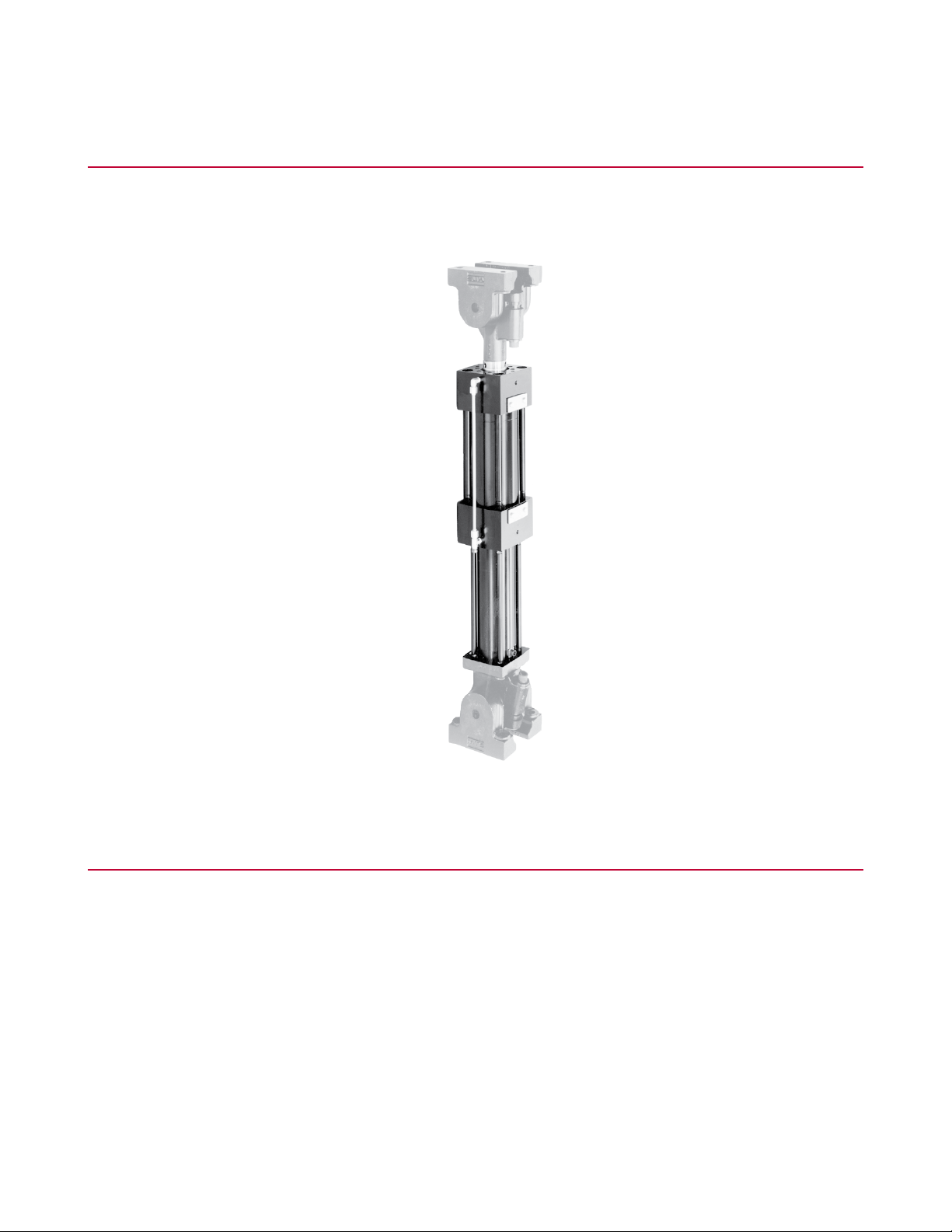
The Series 244 Actuator is a hydraulically powered device that provides displacement of (or forces into) a
specimen or structure for testing.
What You Need to Know
MTS Systems Corporation assumes that you know how to use your controller. See the appropriate manual
for information about performing any controller-related step in this manual’s procedure. You are expected to
know how to perform the following procedures:
• Turn hydraulic pressure on and off.
• Select a control mode.
• Manually adjust the actuator position.
• Install a specimen.
• Define a simple test.
• Run a test.
14 Series 244 Actuators Product Information
Page 15
Component Identification
Introduction
Series 244 Actuators Product Information 15
Page 16

Introduction
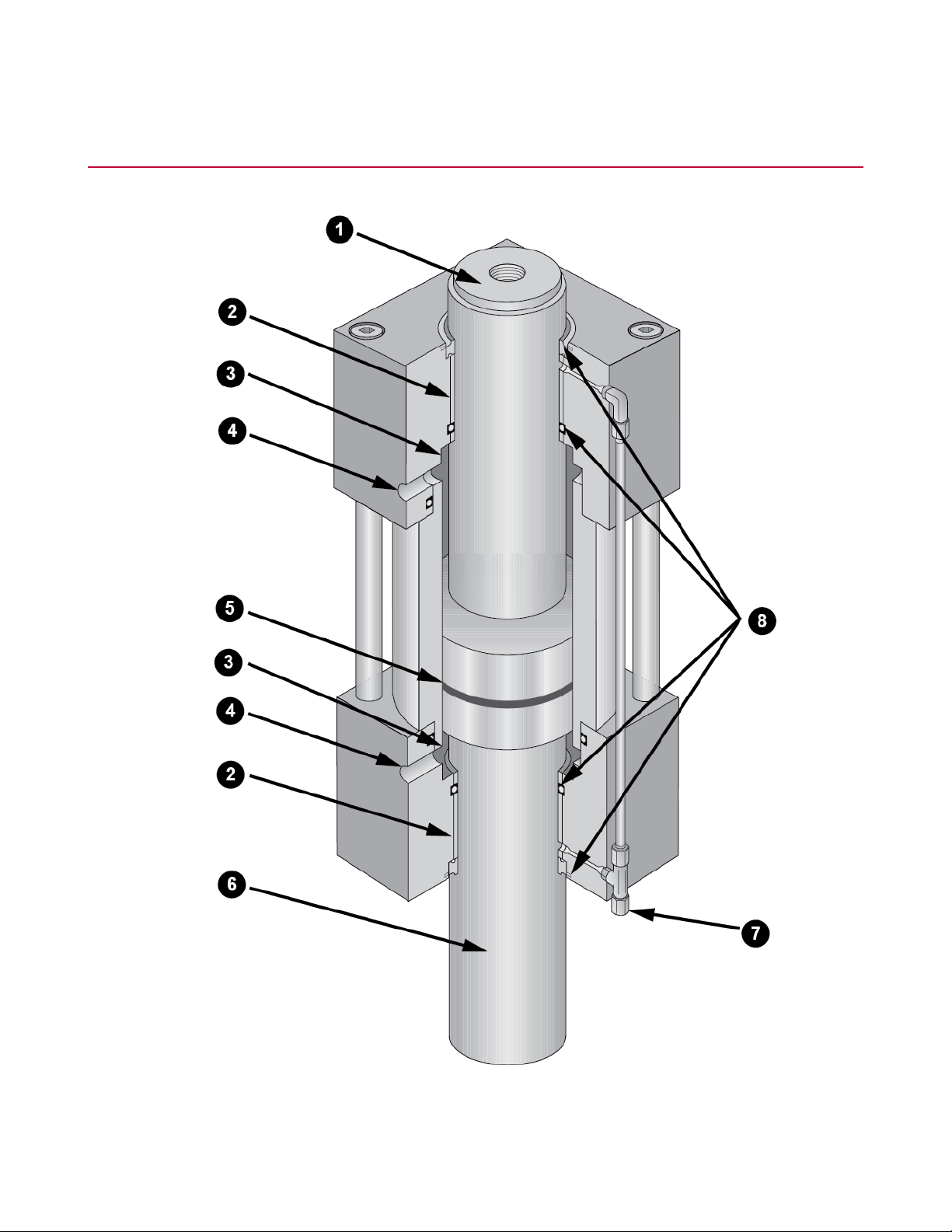
Series 244 Hydraulic Actuator Major Components
DescriptionComponentItem
Piston rod end1
Bearing2
Cushion3
4
Extension Port/
Retraction Port
Piston seal5
The piston rod has a hardened steel insert that provides an
internal thread for mounting load cells, swivels, and interface
fixtures. The Model 244.51 Actuator has no insert; internal
threads are machined directly into the piston rod end.
The high-capacity nonmetallic bearings bond directly to the
end caps. The non-metallic bearings are standard because of
their high side-load tolerance and resistance to failure from
galling and seizure.
The cushions protect the actuator from the effects of
high-speed and high-mass forces. They prevent the actuator
from contacting the end caps. The Model 244.41 and 244.51
Actuators do not have hydraulic cushions.
High-pressure hydraulic fluid enters the cylinder through one
of these control ports. As pressure is applied to one port, the
other port is opened to a return line causing the actuator to
extend or to retract. Fluid flow through these ports is controlled
by the servovalve.
A reinforced Teflon seal (if equipped) on the piston provides
a positive seal and reduces friction. Grooves on the piston
lubricate the piston surface during short-stroke, side-loaded
tests. For high-speed cyclic testing applications, the piston
seal can be omitted. The close tolerance fit provides an
effective viscous seal.
Piston rod6
Drainback Port7
8
High/Low Pressure
Seals
The Series 244 Actuator is equipped with a double-ended
piston rod. The double-ended piston has equal areas on both
sides for balanced performance. It is machined from a single
piece of heat-treated alloy steel and is hard-chrome plated.
The piston rod is hollow to allow for installation and accurate
alignment of a displacement transducer.
The drainback port allows fluid that manages to leak past the
seals to be routed out of the actuator which prevents pressure
pockets from interfering with actuator performance.
The piston rod seals consist of a high-pressure seal and a
low-pressure/wiper seal in both the front end cap and the rear
end cap.
Model 244.1x and 244.2x Actuators [with force ratings under
100 kN (22 kip)], that are used in load frame/unit applications
do not contain high-pressure piston rod seals.
The high-pressure seal is designed for long life, low friction,
and exceptional performance in high-frequency,
low-displacement applications. A small amount of hydraulic
fluid is allowed to flow past the high-pressure seal for
continuous bearing lubrication. Drainback ports return the
16 Series 244 Actuators Product Information
Page 17

DescriptionComponentItem
hydraulic fluid passed by the high-pressure seal back to the
system hydraulic power supply.
The inner part of the low-pressure/wiper seal provides a
hydraulic seal, while the outer part of the seal functions as a
scraper ring to minimize external contamination of the seals
and bearings. When a high-pressure seal is present, the inner
part of the low-pressure seal wipes hydraulic fluid that gets by
the high-pressure seal and guides the fluid into the drainback
port.
Functional Description
The Series 244 Actuator is a double-acting, double-ended, heavy-duty actuator that operates under precision
servovalve control in MTS closed-loop servohydraulic systems. The actuator is a hydraulically powered piston
that can extend or retract (double-acting). The actuator provides displacement of (or force into) a specimen
or structure for testing. It can also provide equal power in tension and compression (double-ended). The
actuator includes an LVDT which measures the displacement of the actuator.
Introduction
The Series 244 Actuator is linear and is associated with axial control channels. A linear actuator consists of
a cylinder that contains a piston.
The Series 244 Actuator is designed to accept a wide variety of options and accessories including force and
displacement transducers, pedestal bases, swivel rod ends, and swivel bases. When equipped with the
appropriate options and accessories, the actuator can be configured for precision testing of materials,
structures, and components.
Series 244 Actuators Product Information 17
Page 18
Introduction
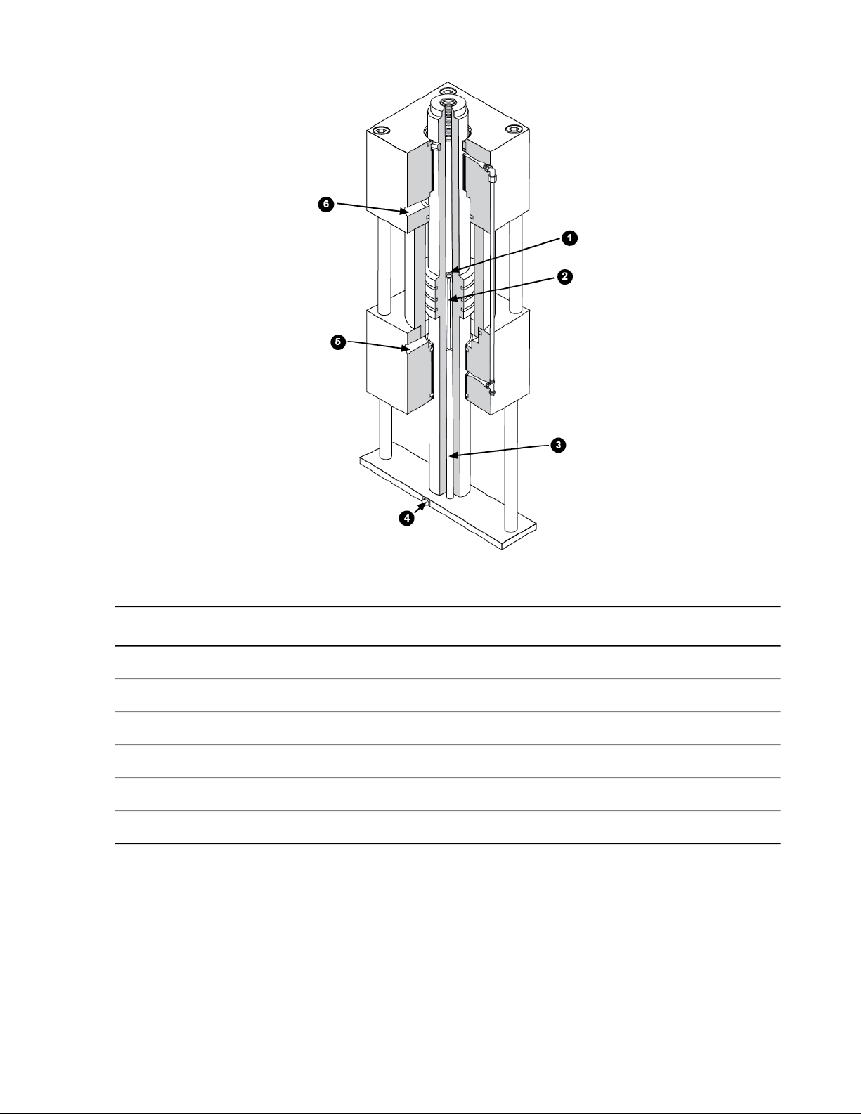
Functional Diagram
DescriptionItem
LVDT Core Mount1
LVDT Core Extension2
LVDT Coil3
LVDT Connector4
Extension Port5
Retraction Port6
About Actuator Mounting
The actuator can be mounted to a wide variety of fixtures and assemblies:
• Component test systems usually have one end of the actuator connected to a custom test frame base
and the other end connected to the test specimen. Either end of the actuator may use mounting fixtures
(such as swivels) to attach it to the specimen or base.
18 Series 244 Actuators Product Information
Page 19
• Material test systems usually mount the actuator in a load unit assembly. The actuator can be mounted
below the base plate or above the crosshead. The end of the actuator uses fixtures (such as grips) to
attach the test specimen to it.
Actuator Operation
Actuator piston rod movement is accomplished by supplying high- pressure hydraulic fluid to one side of the
actuator piston and opening the other side to a return line. High-pressure hydraulic fluid is ported into the
cylinder through the retraction port or the extension port. The differential pressure across the piston forces
the piston rod to move. The amount of hydraulic fluid and the speed and direction of piston rod movement is
controlled by a servovalve.
If the piston rod contacts some external reaction point, then a force is applied to that point equal to the effective
piston area times the actuating pressure. The main criteria for selecting an actuator are the force and stroke
(displacement) required for the job.
LVDT Operation
The internally mounted LVDT (linear variable differential transformer) provides an indication of the actuator
piston rod displacement.
Introduction
Series 244 Actuators Product Information 19
Page 20

Introduction
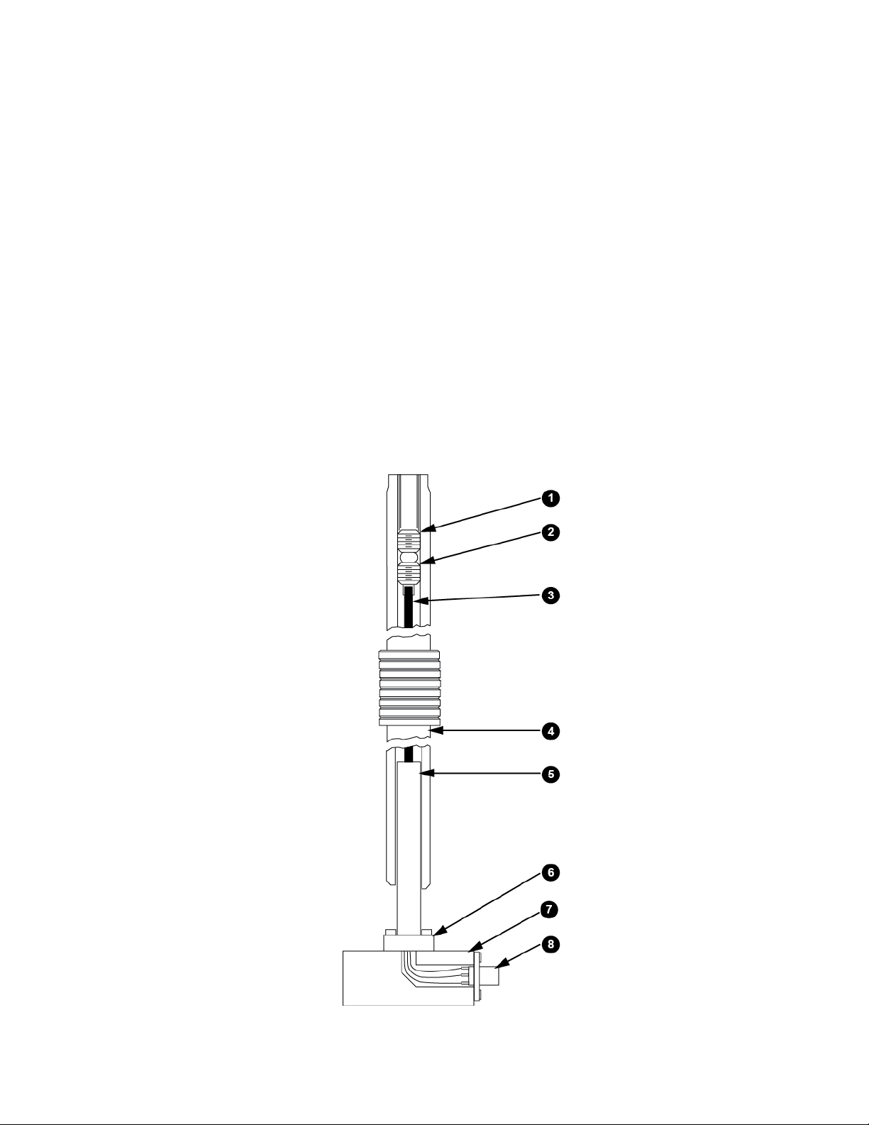
LVDT Components
DescriptionItem
Locking Setscrew1
Core Mount Setscrew2
LVDT Core Extension3
Hollow Piston Rod4
LVDT Coil5
Locking Collar6
Pedestal Base7
LVDT Connector8
The LVDT is an electromechanical device that provides an output voltage which is proportional to the
displacement of a moveable core extension. The core extension is mounted inside the hollow piston rod and
moves as the piston rod moves. The LVDT coil is secured to the pedestal base by a locking collar. The core
extension is positioned in the LVDT coil to provide a zero reference point, and is locked in place with a locking
setscrew.
As the piston rod moves during operation, the output voltage from the LVDT indicates how far the piston rod
has moved from the zero reference point.
Specifications
Several types of specifications are listed on the following pages. All specifications are subject to change
without notice. Contact MTS for verification of specifications critical to your needs.
Force Ratings
The following table lists the force rating of each actuator model. The rod diameter and effective piston area
specifications are used in the “Operating Considerations.”
Actuator Specifications (Metric)
Model
Number
Force Rating
Kn
1
Rod Diameter
mm
Effective Piston Area
2
cm
7.5044.515244.11
1
Nominal force achieved with 21 MPa (3000 psi) hydraulic pressure.
20 Series 244 Actuators Product Information
13.5044.525244.12
Page 21

Introduction
Model
Number
Model
Number
Force Rating
Kn
Actuator Specifications (U.S. Customary)
Force Rating
Kip
1
2
Rod Diameter
mm
Rod Diameter
in
Effective Piston Area
2
cm
33.6869.968244.20
25.1669.950244.21
48.8469.9100244.22
82.1369.9160244.23
126.6595.3250244.31
248.28133.4500244.41
487.70152.41000244.51
Effective Piston Area
2
in
Environmental and Hydraulic Fluid Recommendations
1.171.753.3244.11
2.101.755.5244.12
5.222.7515.0244.20
3.902.7511.0244.21
7.572.7522.0244.22
12.732.7535.0244.23
19.633.7555.0244.31
38.485.25110.0244.41
75.606.00220.0244.51
For use in a controlled environment.Environmental
1
Nominal force achieved with 21 MPa (3000 psi) hydraulic pressure.
2
Nominal force achieved with 21 MPa (3000 psi) hydraulic pressure.
Series 244 Actuators Product Information 21
Page 22

Introduction
5–40°C (41–104°F)Operating temperature
0–85% noncondensingHumidity
< 630 kcal/hr (2500 Btu/hr)Heat load
63 dB (A) fully compensatedNoise3rating at 1 m
Exxon Mobil DTE 25 or Shell Tellus 46 AWHydraulic fluid
43–49°C (110–120°F)Typical operating temperature range
3 microns nominalFiltration (microns)
3
Sound pressure level [db (A)] is expressed as a free field value. Readings may vary with the acoustic
environment.
22 Series 244 Actuators Product Information
Page 23

Dimensions
Introduction
Series 244 Actuators Product Information 23
Page 24

Introduction
Actuator Dimensions
DescriptionItem
BASIC CYLINDER1
FRONT END CAP2
REAR END CAP3
A (Cushion)4
Stroke Length5
C min.6
B+ Stroke Length7
-6 Drain8
Rod Insert: “M” thread size, “N” deep9
Structural10
Load Frame11
“D” holes, “E” thread size, “F” deep, equally spaced on a “G” diameter12
4 holes, “H” thread size, “F” deep, equally spaced on an “L” diameter13
8 holes, “H” thread size, “K” deep, spaced as shown on an “L” diameter14
Each dimension shown in this figure is listed in the table that follows.
Actuator Dimensions (SI Metric)
ModelItem
4
244.51244.41244.31244.23244.22244.21244.20244.12244.11Units
nonenone5.16.47.610.210.215.215.2mmA
342.6311.6256.5233.7233.7246.4246.4238.3238.3mmB
38.128.425.425.425.425.425.425.425.4mmC
D
5
4
This area includes a fully retracted standard length piston rod.
5
Load unit actuators have four mounting holes; structural actuators have two mounting holes.
24 Series 244 Actuators Product Information
88888882 or 42 or 4holes
1 - 81 - 85/8 - 111/2 - 131/2 - 131/2 - 131/2 - 133/8 - 163/8 - 16UNCE
Page 25

Introduction
ModelItem
244.51244.41244.31244.23244.22244.21244.20244.12244.11Units
44.544.525.419.119.119.119.119.119.1mmF
263.4263.4139.7104.1104.1104.1104.181.381.3mmG
1 - 87/8 - 97/8 - 95/8 - 115/8 - 115/8 - 115/8 - 113/8 - 163/8 - 16UNCH
44.538.138.125.425.425.425.419.119.1mmK
280.9254.0191.3127.0127.0127.0127.088.988.9mmL
6
2 - 1212/2 - 121 - 141 - 141 - 141 - 141/2 - 201/2 - 20UNSM
3 - 12
mmM
M12 x
1.25
1.25
M76 x 2M52 x 2M36 x 2M27 x 2M27 x 2M27 x 2M27 x 2M12 x
7
114.33129.8106.250.376.776.776.744.544.5mmN
8
387.4298.5215.9165.1152.4139.7127.0101.6101.6mmP
Actuator Dimensions (U.S. Customary)
ModelItem
244.51244.41244.31244.23244.22244.21244.20244.12244.11Units
nonenone0.200.250.300.400.400.600.60in.A
13.4912.2710.109.209.209.709.709.389.38in.B
1.501.121.001.001.001.001.001.001.00in.C
9
D
10
88888882 or 42 or 4holes
6
Does not use a threaded rod insert
7
Does not use a threaded rod insert.
8
From end of piston rod to bottom of internal threads.
9
This area includes a fully retracted standard length piston rod.
10
Load unit actuators have four mounting holes; structural actuators have two mounting holes.
Series 244 Actuators Product Information 25
1 - 81 - 85/8 - 111/2 - 131/2 - 131/2 - 131/2 - 133/8 - 163/8 - 16UNCE
1.751.751.000.750.750.750.750.750.75in.F
10.3710.375.504.104.104.104.103.203.20in.G
1 - 87/8 - 97/8 - 95/8 - 115/8 - 115/8 - 115/8 - 113/8 - 163/8 - 16UNCH
Page 26

Introduction
ModelItem
12
LVDT Housing Specifications
244.51244.41244.31244.23244.22244.21244.20244.12244.11Units
1.751.501.501.001.001.001.000.750.75in.K
11.0610.007.535.005.005.005.003.503.50in.L
3 - 122 - 1212/2 - 121 - 141 - 141 - 141 - 141/2 - 201/2 - 20UNSM
11
13
5.114.181.983.023.023.021.751.75in.N
4.50
15.2511.758.506.506.005.505.004.004.00in.P
11
Does not use a threaded rod insert.
13
Does not use a threaded rod insert.
12
From end of piston rod to bottom of internal threads.
26 Series 244 Actuators Product Information
Page 27

Open LVDT Housing
DescriptionItem
Cushion1
Stroke Length2
A min.3
68.6 mm (2.70 in) +Stroke Length4
Rear End Cap LVDT Mounting5
4 holes, “B” thread size, “C” deep, spaced as shown6
2 holes, “B” thread size, “C” deep, spaced as shown7
Open Housing LVDT Specifications For Extra Piston Length*
Introduction
Model
1415161718
†,‡
DCBA
Weight
§
lbkginmminmmUNCinmm
3917.7N/AN/A0.7519.13/8-165.90149.9244.11
4118.6N/AN/A0.7519.13/8-165.90149.9244.12
7.07179.6244.21
7.07179.6244.20
7.07179.6244.22
7.07179.6244.23
#
#
#
#
12255.3N/AN/A1.0025.43/8-16
12657.1N/AN/A1.0025.43/8-16
13360.3N/AN/A1.0025.43/8-16
15168.5N/AN/A1.0025.43/8-16
282127.93.0677.70.6015.23/8-168.85224.8244.31
645292.63.96100.60.6015.23/8-169.25234.9244.41
1135514.83.96100.60.6015.23/8-169.82249.4244.51
14
* Specifications not listed in this table can be found in the table called “Dimensions.”
15
† This specification applies to a fully retracted standard extra length piston rod.
16
‡ Optional rod lengths are available for crosshead actuator mounting or other special mounting configurations.
17
§ For a 152 mm (6 in) stroke basic load frame/load unit cylinder assembly and open housing LVDT.
18
# Requires 5/8-11 to 3/8-16 insert thread (supplied on open housing LVDT assembly).
Series 244 Actuators Product Information 27
Page 28

Introduction
Closed LVDT Housing
DescriptionItem
Stroke + A1
Spiral Washers or Adapter2
Model
1920212223
Closed Housing LVDT3
Closed Housing LVDT Specifications*
†
BA
Weight
mminmm
3.1880.8244.11
3.1880.8244.12
2.7670.2244.21
2.7670.2244.20
––––
––––
––––
––––
‡
lbkgin
§
§
§
§
§
§
§
§
4319.5––––
4520.4––––
12456.2––––
12858.1––––
13561.21.0426.42.7670.2244.22
15369.41.0426.42.7670.2244.23
295133.81.3033.02.3669.9244.31
#
1.9649.8244.41
0.389.6244.51
92.0
#
#
712322.93.62
1307592.84.00 5101.6
19
* Specifications not listed in this table can be found in the table called “Dimensions.”
20
† Refers to the length of the closed housing LVDT assembly.
21
‡ For a 152 mm (6 in) stroke basic load frame/load unit cylinder assembly and open housing LVDT.
22
§ Do not require spiral washers or an adapter
23
# Use an adapter instead of spiral washers.
28 Series 244 Actuators Product Information
Page 29

Pedestal Base Specifications
Introduction
mm
Pedestal Base Specifications
WeightDCBAModel
inmminmmin
lbkginmm
5.95.50139.74.50114.30.5614.21.5038.1244.11
13
135.95.50139.74.50114.30.5614.21.5038.1244.12
2712.27.38187.45.75146.00.6817.31.7544.4244.21
2712.27.38187.45.75146.00.6817.31.7544.4244.20
2712.27.38187.45.75146.00.6817.31.7544.4244.22
2712.27.38187.45.75146.00.6817.31.7544.4244.23
5826.39.00228.67.25184.20.9423.92.5063.5244.31
13762.113.88352.611.00279.41.3133.32.5063.5244.41
16574.814.00355.611.00279.41.5639.63.0076.2244.51
Series 244 Actuators Product Information 29
Page 30

Page 31

Safety
Topics:
•
General Safety Practices: Hydraulic Power Units and Hydraulic Service Manifolds.............................32
•
Safety Practices Before Operating the System.....................................................................................33
•
Safety Practices While Operating the System ......................................................................................37
•
Hazard Placard Placement....................................................................................................................38
Series 244 Actuators Product Information 31
Page 32

Safety
General Safety Practices: Hydraulic Power Units and Hydraulic Service Manifolds
The hydraulic power unit (HPU) provides high pressure hydraulic fluid to system components for system
operation. The hydraulic service manifold (HSM) controls distribution of that hydraulic fluid pressure. This
section provides general information about safety issues that pertain to system hydraulic supply and distribution
components. These issues include statements to the intended use and foreseeable misuse of the system
and definition for the graphical hazard labeling that is affixed to your product, and other (more general) safety
information that relates to the high-pressure and high-performance characteristics of MTS servohydraulic
and electromechanical systems.
When you prepare to operate a system that includes hydraulic components, ensure the following:
• Do not use or allow personnel to operate the system who are not experienced, trained, or educated in the
inherent dangers associated with high-performance servo hydraulics and who are not experienced, trained,
or educated with regard to the intended operation as it applies to this test system.
• Do not disable safety components or features (including limit detectors, light curtains, or proximity
switches/detectors).
• Do not attempt to operate the system without appropriate personal safety gear (for example, hearing,
hand, and eye protection).
• Do not modify the system or replace system components using parts that are not MTS component parts
or effect repairs using parts or components that are not manufactured to MTS specifications.
• Do not use the system in a test area where uncontrolled access to the test system is allowed when the
system is in operation.
• For servohydraulic systems, do not operate the system unless an interlock is installed to monitor supply
pressure into the HSM and initiate a system interlock if a low or no pressure event occurs.
• Mists of DTE 25 are combustible. Refer to MSDS. Customer is responsible for fire prevention measures
as per facility or building or other local regulations and codes
If you have system related responsibilities (that is, if you are an operator, service engineer, or maintenance
person), you should study safety information carefully before you attempt to perform any test system procedure.
You should receive training on this system or a similar system to ensure a thorough knowledge of your
equipment and the safety issues that are associated with its use. In addition, you should gain an understanding
of system functions by studying the other manuals supplied with your test system. Contact MTS for information
about the content and dates of training classes that are offered.
It is very important that you study the following safety information to ensure that your facility procedures and
the system’s operating environment do not contribute to or result in a hazardous situation. Remember, you
cannot eliminate all the hazards associated with this system, so you must learn and remain aware of the
hazards that apply to your system at all times. Use these safety guidelines to help learn and identify hazards
so that you can establish appropriate training and operating procedures and acquire appropriate safety
equipment (such as gloves, goggles, and hearing protection).
Each test system operates within a unique environment which includes the following known variables:
• Facility variables (facility variables include the structure, atmosphere, and utilities)
• Unauthorized customer modifications to the equipment
• Operator experience and specialization
32 Series 244 Actuators Product Information
Page 33

• Test specimens
Because of these variables (and the possibility of others), your system can operate under unforeseen
circumstances that can result in an operating environment with unknown hazards.
Improper installation, operation, or maintenance of your system can result in hazardous conditions that can
cause death, personal injury, or damage to the equipment or to the specimen. Common sense and a thorough
knowledge of the system’s operating capabilities can help to determine an appropriate and safe approach to
its operation.
Safety Practices Before Operating the System
Before you apply power to the test system, review and complete all of the safety practices that are applicable
to your system. The goal, by doing this, is to improve the safety awareness of all personnel involved with the
system and to maintain, through visual inspections, the integrity of specific system components.
Read all manuals
Study the contents of this manual and the other manuals provided with your system before attempting to
perform any system function for the first time. Procedures that seem relatively simple or intuitively obvious
can require a complete understanding of system operation to avoid unsafe or dangerous situations.
Safety
Locate lockout/tagout points
Know where the lockout/tagout point is for each of the supply energies associated with your system. This
includes the hydraulic, pneumatic, electric, and water supplies (as appropriate) for your system to ensure
that the system is isolated from these energies when required.
Know facility safe procedures
Most facilities have internal procedures and rules regarding safe practices within the facility. Be aware of
these safe practices and incorporate them into your daily operation of the system.
Locate Emergency Stop buttons
Know the location of all the system Emergency Stop buttons so that you can stop the system quickly in an
emergency. Ensure that an Emergency Stop button is located within close proximity of the operator at all
times.
Know controls
Before you operate the system for the first time, make a trial run through the operating procedures with the
power off. Locate all hardware and software controls and know what their functions are and what adjustments
they require. If any control function or operating adjustment is not clear, review the applicable information
until you understand it thoroughly.
Have first aid available
Accidents can happen even when you are careful. Arrange your operator schedules so that a properly trained
person is always close by to render first aid. In addition, ensure that local emergency contact information is
posted clearly and in sight of the system operator.
Series 244 Actuators Product Information 33
Page 34

Safety
Know potential crush and pinch points
Be aware of potential crush and pinch points on your system and keep personnel and equipment clear of
these areas.
An important consideration for servohydraulic systems is that when power is interrupted, it is likely that stored
accumulator pressure will persist for some time within the system. In addition, it is likely that as stored energy
dissipates, gravity will cause portions of the system to move.
Be aware of component movement with hydraulics off
For hydraulic systems, be aware that mechanical assemblies can shift or drift due to changes within hydraulic
hardware when hydraulics are turned off. This non-commanded movement is because oil can transfer between
the pressure and return ports and across internal components of the hydraulic hardware. Be aware that this
can happen and clear the area around the mechanical assemblies when hydraulics are turned off.
Know electrical hazards
When the system electrical power is turned on, minimize the potential for electrical shock hazards. Wear
clothing and use tools that are properly insulated for electrical work. Avoid contact with exposed wiring or
switch contacts.
Whenever possible, turn off electrical power when you work on or in proximity to any electrical system
component. Observe the same precautions as those given for any other high-voltage machinery.
Make sure that all electrical components are adequately grounded. Grounds must remain connected and
undisturbed at all times.
Ensure Correct Cable Connection
If a system cable has been disconnected, ensure that you establish the correct cable-to-connector relationship
during reconnection. Incorrect cable connections can result in improper servo loop phasing or an open servo
loop condition, either of which can cause unstable or unexpected and potentially dangerous system motions.
Verify the correct cable-to-connector relationship by observing the cable and connector labeling and the
system wiring schematics.
Keep bystanders safely away
Keep bystanders at a safe distance from all equipment. Never allow bystanders to be in close proximity of
specimens or equipment while the test is running.
Wear proper clothing
Do not wear neckties, shop aprons, loose clothing or jewelry, or long hair that could get caught in equipment
and result in an injury. Remove loose clothing or jewelry and restrain long hair.
Remove flammable fluids
Remove flammable fluids from their containers or from components before you install the container or
component. If desired, you can replace the flammable fluid with a non-flammable fluid to maintain the proper
proportion of weight and balance.
Know compressed gas hazards
Your system may contain accumulators that require a high-pressure gas precharge (pressures that exceed
138 bar [2000 psi]). High-pressure devices are potentially dangerous because a great amount of energy is
available in the event of an uncontrolled expansion or rupture.
Observe the following safety practices when you work with high-pressure air or gases:
34 Series 244 Actuators Product Information
Page 35

Safety
• When you charge an accumulator, follow all the charging instructions provided in the appropriate product
information manuals. When precharging accumulators, properly identify the type of gas to be used and
the type of accumulator to be precharged.
• Use only dry-pumped nitrogen to precharge nitrogen-charged accumulators. (Dry-pumped nitrogen can
also be labeled “oil pumped” or “dry water pumped.”) Do not use compressed air or oxygen for precharging:
the temperature increase caused by rapid gas compression can result in highly explosive conditions when
hydraulic fluid is in the presence of oxygen or compressed air.
• Always follow the recommended bleeding procedures before you remove or disassemble components
that contain pressurized gas. When you bleed a gas or remove a fitting, hose, or component that contains
a gas, remember that many gases cannot support life. Therefore, as the ratio of released gas to oxygen
increases, so does the potential for suffocation.
• Wear appropriate safety devices to protect your hearing. Escaping air or gas can create a noise level that
can damage your hearing.
• Ensure that all pressurized air or gas is bled out of a pneumatic or gas-charged device before you start
to disassemble it. A thorough understanding of the assembly and its pressurized areas is necessary before
you undertake any maintenance. Refer to the appropriate product information for the correct bleeding
procedure.
It may not be obvious or intuitive which bolts or fittings are used to restrain a pressurized area. On some
assemblies, you must remove a cover plate to gain access to the structural bolts. Sometimes, to protect
you from a rapid release of trapped gases, a small port is exposed when you remove this cover plate.
Exposing this port ensures that the gas precharge is fully bled before disassembly. However, this is not
the recommended procedure for bleeding a pneumatic or gas-charged device, because it can expose you
to the dangers of escaping compressed gas and particulates that are expelled from the chamber or around
the seals. Do not assume that cover plates and ports are installed in all the critical locations.
Consult MTS when in doubt about the safety or reliability of any system-related procedure or modification
that involves devices that contain any type of compressed gas.
Check bolt ratings and torques
To ensure a reliable product, fasteners (such as bolts and tie rods) used in MTS-manufactured systems are
torqued to specific requirements. If a fastener is loosened or the configuration of a component within the
system is modified, refer to the system and component assembly drawings (located on the System
Documentation CD) to determine the correct fastener, fastener rating, and torque. Over torquing or under
torquing a fastener can create a hazardous situation due to the high forces and pressures present in MTS
test systems.
On rare occasions, a fastener can fail even when it is correctly installed. Failure usually occurs during torquing,
but it can occur several days later. Failure of a fastener can result in a high velocity projectile. Therefore, it
is a good practice to avoid stationing personnel in line with or below assemblies that contain large or long
fasteners.
Practice good housekeeping
Keep the floors in the work area clean. Industrial chemicals, such as hydraulic fluid, that are spilled on any
type of floor can result in a dangerous, slippery surface. Do not leave tools, fixtures, or other items not specific
to the test, lying about on the floor, system, or decking.
Protect hoses and cables
Protect electrical cables from spilled fluids and from excessive temperatures that can cause the cables to
harden and eventually fail. Ensure that all cables have appropriate strain relief devices installed at the cable
and near the connector plug. Do not use the connector plug as a strain relief.
Series 244 Actuators Product Information 35
Page 36

Safety
Protect all system hoses and cables from sharp or abrasive objects that can cause the hose or cable to fail.
Use a cable cover or cable tray where cables are in traffic locations. Never walk on hoses or cables or move
heavy objects over them. Route hoses and cables away from areas that expose them to possible damage.
Provide proper hydraulic fluid filtration
For hydraulic systems equipped with a non-MTS hydraulic power unit, make sure that hydraulic fluid filtration
is established to maintain fluid cleanliness standards as stated in the Hydraulic Fluid Care Manual (see the
System Documentation CD). Particles present in the hydraulic fluid can cause erratic or poor system response.
Protect accumulators from moving objects
For systems equipped with accumulators, protect accumulators with supports or guards. Do not strike
accumulators with moving objects. This could cause the accumulator(s) to separate from the manifold resulting
in equipment damage and personal injury.
Record changes
If you change any operating procedure, write the change and the date of the change in the appropriate manual.
Provide test area guards
Use protective guards such as cages, enclosures, and special laboratory layouts when you work with hazardous
test specimens (for example, brittle or fragmenting materials or materials that are internally pressurized).
Do not exceed the Maximum Supply Pressure
For hydraulic systems and components, make sure that hydraulic supply pressure is limited to the maximum
pressure defined by the system operating limits. Read and review “System Operating Limits” for the system.
Do not disable safety devices
Your system may have active or passive safety devices installed to prevent system operation if the device
indicates an unsafe condition. Do not disable such devices as it may result in unexpected system motion.
Use appropriately sized fuses
Whenever you replace fuses for the system or supply, ensure that you use a fuse that is appropriately sized
and correctly installed. Undersized or oversized fuses can result in cables that overheat and fuses that explode.
Either instance creates a fire hazard.
Provide adequate lighting
Ensure adequate lighting to minimize the chance of operation errors, equipment damage, and personal injury.
Provide adequate ventilation
Make sure work and maintenance areas are adequately ventilated to minimize the risks associated with the
collection of hazardous fumes (such as vaporized hydraulic fluid). This is of special concern in confined areas
where hydraulic equipment is operating at high pressure in confined areas.
Provide means to access out-of-reach components
Make sure you can access system components that might be out of reach while standing on the floor. For
example, ladders or scaffolding might be required to reach load cell connectors on tall load units.
36 Series 244 Actuators Product Information
Page 37

Safety Practices While Operating the System
Wear appropriate personal protection
Wear eye protection when you work with high-pressure hydraulic fluid, high-pressure air pressure, breakable
specimens, or when anything characteristic to the specimen could break apart.
Wear ear protection when you work near electric motors, pumps, or other devices that generate high noise
levels. This system may create sound pressure levels that exceed 70 dbA during operation.
Wear appropriate protection (gloves, boots, suits, respirators) whenever you work with fluids, chemicals, or
powders that may irritate or harm the skin, respiratory system, or eyes.
Provide test area enclosures
Use protective enclosures such as cages or shields, and special laboratory layouts when you work with
hazardous test specimens (for example, brittle or fragmenting materials or materials that are internally
pressurized).
Customer must evaluate risks due to ejected parts or materials from the test specimens. If the MTS Test Area
Enclosure option is not selected by the customer, then for protection against ejected parts or materials from
test specimens and to control access to the machinery, the Customer must provide a Test Area Enclosure
to protect personnel.
Safety
Specimen temperature changes
During cyclic testing, the specimen temperature can become hot enough to cause burns. Wear personal
protection equipment (gloves) when handling specimens.
Handle chemicals safely
Whenever you use or handle chemicals (for example, hydraulic fluid, batteries, contaminated parts, electrical
fluids, and maintenance waste), refer to the appropriate MSDS documentation for that material and determine
the appropriate measures and equipment required to handle and use the chemical safely. Ensure that the
chemical is disposed of appropriately.
Know servohydraulic system interlocks
Interlock devices should always be used and properly adjusted. Interlock devices are designed to minimize
the chance of accidental damage to the test specimen or the equipment. Test all interlock devices for proper
operation immediately before a test. Do not disable or bypass any interlock devices as doing so could allow
hydraulic pressure to be applied regardless of the true interlock condition. The Reset/Override button is a
software function that can be used to temporarily override an interlock while attempting to start the hydraulic
power unit and gain control of the system.
Know system limits
Never rely on system limits such as mechanical limits or software limits to protect you or any personnel.
System limits are designed to minimize the chance of accidental damage to test specimens or to equipment.
Test all limits for proper operation immediately before a test. Always use these limits and adjust them properly.
Do not disturb sensors
Do not bump, wiggle, adjust, disconnect, or otherwise disturb a sensor (such as an accelerometer or
extensometer) or its connecting cable when hydraulic pressure is applied.
Series 244 Actuators Product Information 37
Page 38

Safety
Ensure secure cables
Ensure that all cable connections (electrical supply, control, feedback, sensor, communications, and so forth)
are either locking type, or are secured, to ensure that they cannot be disconnected by a simple act. Do not
change any cable connections when electrical power or hydraulic pressure is applied. If you attempt to change
a cable connection while the system is in operation, an open control loop condition can result. An open control
loop condition can cause a rapid, unexpected system response which can result in severe personal injury,
death, or damage to equipment. Also, ensure that all cables are connected after you make any changes in
the system configuration.
Stay alert
Avoid long periods of work without adequate rest. In addition, avoid long periods of repetitious, unvarying, or
monotonous work because these conditions can contribute to accidents and hazardous situations. If you are
too familiar with the work environment, it is easy to overlook potential hazards that exist in that environment.
Contain small leaks
Do not use your fingers or hands to stop small leaks in hydraulic or pneumatic hoses. Substantial pressures
can build up, especially if the hole is small. These high pressures may cause the oil or gas to penetrate your
skin, causing painful and dangerously infected wounds. Turn off the hydraulic supply and allow the hydraulic
pressure to dissipate before you remove and replace the hose or any pressurized component.
Stay clear of moving equipment/avoid crush points
Stay clear of mechanical linkages, connecting cables, and hoses that move because you may get pinched,
crushed, tangled, or dragged along with the equipment. High forces generated by the system can pinch, cut,
or crush anything in the path of the equipment and cause serious injury. Stay clear of any potential crush
points. Most test systems can produce sudden, high-force motion. Never assume that your reactions are fast
enough to allow you to escape injury when a system fails.
Know the causes of unexpected actuator motions
The high force and velocity capabilities of MTS actuators can be destructive and dangerous (especially if
actuator motion is unexpected). The most likely causes of unexpected actuator response are operator error
and equipment failure due to damage or abuse (such as broken, cut, or crushed cables and hoses; shorted
wires; overstressed feedback devices; and damaged components within the servocontrol loop). Eliminate
any condition that could cause unexpected actuator motion.
Do not use RF transmitters
Keep radio frequency (RF) transmitters away from the workstation computers, remote terminals, and electronics
consoles. Intense RF fields can cause erratic operation of the more sensitive circuits in the system.
Hazard Placard Placement
Hazard placards contain specific safety information and are affixed directly to the system so they are plainly
visible.
Each placard describes a system-related hazard. When possible, international symbols (icons) are used to
graphically indicate the type of hazard and the placard label indicates its severity. In some instances, the
placard may contain text that describes the hazard, the potential result if the hazard is ignored, and general
instructions about how to avoid the hazard.
38 Series 244 Actuators Product Information
Page 39

Labels And Icons
The following labels and icons may be found on an actuator.
Warning Label
Part #46-140-101
Safety
WARNING
Hydraulic pressure above 3000 psi can rupture components. Can cause severe personal injury or damage
to equipment.
Do not exceed 3000 psi (20.7 MPa).
Read instructions before operating or servicing.
Warning Label
Part #46-140-201
WARNING
Hydraulic pressure above 4000 psi can rupture components. Can cause severe personal injury or damage
to equipment.
Do not exceed 4000 psi (27.6 MPa).
Read instructions before operating or servicing.
Series 244 Actuators Product Information 39
Page 40

Safety
Caution Label
Part #045-283-501
CAUTION
High drain pressure can cause rod seal damage and hydraulic oil leakage.
Remove drain line shipping cap and connect drain hose before operating.
Attached Mass Warning Label
Part #057-230-041
Attached mass warning.
Do not exceed maximum attached mass.
40 Series 244 Actuators Product Information
Page 41

Hydraulic Actuator ID Tag
Part #700-004-198
Hydraulic Actuator ID tag lists the following:
Safety
• Model Number
• Serial Number
• Assembly number/Rev
• Force rating
• Effective Area
• Static Stroke
• Dynamic Stroke
• Hydrostatic/Non-Hydrostatic
• Maximum attached mass
Hydraulic Actuator ID Tag
Part #037-588-801
Series 244 Actuators Product Information 41
Page 42

Safety
Hydraulic Actuator ID tag lists the following:
• Model Number
• Serial Number
• Assembly number/Rev
• Force rating
• Effective Area
• Static Stroke
• Dynamic Stroke
• Hydrostatic/Non-Hydrostatic
Pressure Icon Label
Part #57-237-711
Pressure icon.
Can be used alone, or in conjunction with pressure rating label (Part # 57-238-5xx).
Pressure Rating Label
Part #57-238-5xx
Pressure rating. Actual rating listed on this label will vary. This label is used in conjunction with the Pressure
icon (Part # 57237711). Located directly beneath pressure icon on actuator.
42 Series 244 Actuators Product Information
Page 43

Lift Hole Thread Size
Part #57-806-13
Lift hole. Thread size will be specified on the actual label.
Safety
Series 244 Actuators Product Information 43
Page 44

Page 45

Installation
Topics:
•
About Installation...................................................................................................................................46
•
Load Units..............................................................................................................................................46
•
Installing a Fixture to the Actuator.........................................................................................................47
•
Spiral Washers.......................................................................................................................................50
•
Installing Fixtures with Spiral Washers..................................................................................................51
•
Removing Fixtures with Spiral Washers................................................................................................53
•
LVDT Cable Connection........................................................................................................................54
•
Hydraulic Connections...........................................................................................................................55
Series 244 Actuators Product Information 45
Page 46

Installation
About Installation
Installing the Series 244 Actuator depends on the testing application.
• For materials or component testing, the actuator is typically installed in a load frame or test fixture.
• For structural or vibration testing, the actuator is typically secured to a reaction mass using a swivel or
pedestal base.
Load Units
When the Series 244 Actuator is mounted in a load frame configuration, the actuator is installed in the load
frame at the factory. Actuator options, such as servovalves and manifolds, are also installed on the actuator
at the factory. The only installation required is to connect system hydraulic hoses and system cables.
46 Series 244 Actuators Product Information
Page 47

See the system assembly drawing, system functional drawing, and console assembly drawing (typically
located in a System Reference manual supplied with your system documentation) for information about
hydraulic and electrical connections.
Note:
Actuators mounted in a load unit should not be removed from the load unit. Proper alignment should
not be performed in the field.
When an actuator is mounted in a load frame, the actuator is hidden behind other hydraulic components as
shown here.
Installing a Fixture to the Actuator
Fixtures can be mounted to the pedestal base, the actuator piston rod, or the upper end cap.
The actuator is equipped with an upper end cap and a pedestal base which has from two to eight threaded
mounting holes.
The pedestal base also contains a center position threaded hole which may be used to attach a swivel
mounting accessory. The piston rod also contains a center position threaded hole. This mounting hole is
typically used to attach a swivel mounting accessory or a specimen supporting fixture (shaker head or vibration
table) to the actuator.
Installation
Series 244 Actuators Product Information 47
Page 48

Installation
Note:
See the Series 249 Swivels manual (MTS part number 100-237-294) for more information about using
swivels with the actuator.
Base Types
DescriptionItem
Swivel Base1
Pedestal Base2
Mounting Bolt Specifications
A Series 244 Actuator equipped with a pedestal base or a swivel base typically has the base bolted to a
reaction mass. The following table lists information for the mounting bolt specifications.
48 Series 244 Actuators Product Information
Page 49

Swivel Base Mounting Bolt Specifications
Installation
Model
RecommendedBolt GradeMounting Bolt TorqueRecommendedMounting
Bolt Size
SAEISOlbf-ftN·mUNCmm
12.912.934533/8-16M10 x 1.50244.11
12.912.934533/8-16M10 x 1.50244.12
12.912.91602305/8-11M16 x 2.00244.20
12.912.91602305/8-11M16 x 2.00244.21
12.912.91602305/8-11M16 x 2.00244.22
12.912.91602305/8-11M16 x 2.00244.23
12.912.96807801-8M24 x 3.00244.31
12.912.9140016001 1/4-7M30 x 3.50244.41
12.912.9240032001 1/2-4M42 x 4.50244.51
Pedestal Base Mounting Bolt Specifications
Model
RecommendedBolt GradeMounting Bolt TorqueRecommendedMounting
Bolt Size
SAEISOlbf-ftN·mUNCmm
812.984931/2-13M12 x 1.75244.11
812.984931/2-13M12 x 1.75244.12
812.91602305/8-11M16 x 2.00244.21
812.91602305/8-11M16 x 2.00244.20
812.91602305/8-11M16 x 2.00244.22
812.91602305/8-11M16 x 2.00244.23
812.94544507/8-9M20 x 2.50244.31
812.9140016001 1/4-7M30 x 3.50244.41
812.9240032001 1/2-6M42 x 4.50244.51
Series 244 Actuators Product Information 49
Page 50

Installation
Spiral Washers
The optional Model 601 Spiral Washers are typically used to provide fatigue-resistant connections between
elements of the force train and to minimize the effects of backlash. If the operating procedure requires changing
of preloaded force train elements such as the load cell or grips, the spiral washers must be readjusted.
The spiral washers are placed over the connector studs at each connection, and adjusted to place a constant
preload on the stud.
When cyclic loads below the tensile force level of the preload are applied to the connections, the load is
distributed between the surfaces of the spiral washers and the stud in a ratio of the relative stiffness of the
parts. The spiral washers have a large surface area and therefore greater stiffness. They react to most of the
load and keep the stress in the stud below its fatigue run out level. In addition to providing fatigue-resistant
connections, the spiral washers also minimize the possibility of backlash due to loose-fitting or worn stud
threads.
DescriptionItem
Compliant Material1
Load Cell2
50 Series 244 Actuators Product Information
Force Train Components
Page 51

DescriptionItem
Upper End Cap3
Actuator Rod4
Spiral Washers5
Connector Studs6
Swivel Head7
Installing Fixtures with Spiral Washers
This procedure requires two spanner wrenches and assumes that you are familiar with all operating aspects
of your system.
Installation
Multiple Fixtures With Different Ratings
Sometimes you may have multiple fixtures in the force train that have different force ratings. When installing
the fixtures pretensioned with spiral washers, install the fixtures with the lowest force rating first. Then install
any other fixtures from the lowest to the highest force rating.
1. Ensure that system hydraulic pressure has been reduced to zero before proceeding. To do this, turn off
the hydraulic power unit and exercise the actuator until it stops moving.
2. Clean the connector studs and the internal threads of the force train element(s). Inspect the thread mating
surfaces for signs of contamination or corrosion. All damaged threads should be repaired or the component
replaced.
3. Apply a thin layer of Molykote G paste, or equivalent, to all thread mating surfaces.
4. When installing a load cell, place a small piece of compliant material inside the load cell to keep the stud
from contacting the bottom of the hole (see the figure called “Force Train Components”).
5. Slowly turn the connector stud into an element of the force train (for example, the actuator rod). The
connector stud should turn freely. If any resistance is encountered, disassemble and correct the problem
before proceeding.
Series 244 Actuators Product Information 51
Page 52

Installation
Spiral Washer Rotation
DescriptionItem
Connector Stud1
Spiral Washer Rotation to Increase Thickness2
Medium Thickness3
6. Place the spiral washers together with the spiral surfaces facing each other.
7. Place the set of spiral washers over the connector stud and rotate them until they are at minimum thickness.
Mount the appropriate fixture (load cell, grip, and so forth) on the connector stud and tighten the fixture
against the spiral washers by hand.
8. Repeat Steps 2 through 7 for all spiral washers in the force train of the same rating.
9. Connect a coupling (dummy specimen) in the force train or install the actuator into a suitable fixture such
that it can withstand a tensile load 10 – 20% greater than the maximum load to be applied to the connector
stud during testing.
10. Select force control with the system controller.
52 Series 244 Actuators Product Information
Page 53

Installation
Warning:
Do not exceed the maximum HPS output pressure or apply a force greater than any force
train component capacity.
Exceeding the tensile load capacity of any element in the force train can cause equipment
damage or personal injury.
It is necessary to temporarily exceed the tensile load capacity to achieve the requirements of
Step 5 in this procedure. This is accomplished by increasing the output pressure of the HPU.
Contact MTS Systems Corporation.
11. Turn on the system hydraulic pressure.
Note:
Be sure that all components in the force train can accommodate the required tensile load.
12. Apply a static tensile load 10–20% higher than the maximum load to be applied during testing.
13. If your test requires the maximum tensile load of the force train, you will need to adjust the output pressure
of the HPS to reach the required tensile load.
Caution:
If the spiral washers are not sufficiently tightened, the connector stud can break when subjected
to cyclic loads.
Follow the instructions in Step 13 and ensure that the spiral washers are properly tightened.
14. Using the spanner wrenches, rotate the spiral washers in opposite directions to tighten them. The opening
between the washers must not exceed an arc of 30° from the closed position (see the figure on the previous
page).
15. If more than a 30° arc is created, remove the tensile load from the specimen. Then remove the specimen
and the connector stud. Examine the connector stud for any signs of thread wear. If wear is noticed,
replace the stud and repeat Step 1 through Step 14.
Removing Fixtures with Spiral Washers
This procedure requires two spanner wrenches and assumes that you are familiar with all operating aspects
of your system.
Series 244 Actuators Product Information 53
Page 54

Installation
Multiple Fixtures With Different Ratings
Sometimes you may have multiple fixtures in the force train that have different force ratings. When removing
the fixtures pretensioned with spiral washers, remove the fixtures with the lowest force rating first. Then
remove any other fixtures from the lowest to the highest force rating.
1. Ensure that system hydraulic pressure has been reduced to zero before proceeding. To do this, turn off
the hydraulic power unit and exercise the actuator until it stops moving.
2. Install a dummy specimen or a suitable fixture in the force train such that it can withstand a tensile load
10–20% greater than the maximum load to be applied during testing.
3. Select force control at the system controller.
4. Apply system hydraulic pressure according to applicable system procedures.
Warning:
Do not exceed the maximum HPS output pressure or apply a force greater than any force
train component capacity.
Exceeding the tensile load capacity of any element in the force train can cause equipment
damage or personal injury.
It is necessary to temporarily exceed the tensile load capacity to achieve the requirements of
Step 5 in this procedure. This is accomplished by increasing the output pressure of the HPU.
Contact MTS Systems Corporation.
Note:
Be sure that all components in the force train can accommodate the required tensile load.
5. Apply a static tensile load 10 to 20% higher than the maximum load to be applied during testing.
6. Use the spanner wrenches to rotate the spiral washers to reduce their combined thickness to a minimum.
7. Reduce tensile load to zero and remove hydraulic pressure. Ensure that all residual pressure (including
accumulator pressure) has bled off.
8. Remove all force train components (such as load cell, swivel rod end, grips, or fixtures) attached to the
actuator.
LVDT Cable Connection
The following figure shows the electrical connections of the LVDT. See your controller manual for cable
specifications or cable assembly numbers.
54 Series 244 Actuators Product Information
Page 55

Installation
LVDT Cable Connection
DescriptionItem
Output1
Ground2
Excitation3
Yellow4
Blue5
Green6
Black7
Red8
Hydraulic Connections
Note:
When the Series 244 Actuator is installed in a load unit, the hydraulic connections are made through
a manifold connected to a Series 298 Actuator Manifold.
Hydraulic connections to the Series 244 Actuator are made through a manifold that connects the ports of
each end cap. The manifold has hydraulic pressure and return ports stamped P and R respectively. These
ports are connected to matching ports located on a hydraulic service manifold (HSM).
See the servovalve manual for servovalve installation information.
Series 244 Actuators Product Information 55
Page 56

Installation
Hydraulic Connections
DescriptionItem
Some manifolds support two servovalves.1
Return Port2
Drain Port3
Pressure Port4
Caution:
Do not use inferior quality hydraulic fluids.
Using fluids other than those specified by MTS may cause component or system failure or both.
Use Mobil DTE 25 or Shell Tellus 46 hydraulic fluid only.
56 Series 244 Actuators Product Information
Page 57

Operation
Topics:
•
About Operation.....................................................................................................................................58
•
Actuator ID.............................................................................................................................................58
•
Operating Considerations......................................................................................................................58
•
Sideload Calculation Procedure............................................................................................................59
•
Sample Calculation................................................................................................................................62
Series 244 Actuators Product Information 57
Page 58

Operation
About Operation
This section describes how to use the Series 244 Actuator when side loads are applied during testing.
Warning:
Exceeding the maximum attached mass can cause unpredictable actuator movement.
Unexpected actuator movement can result in injury to personnel or damage to equipment.
Ensure that the maximum attached mass listed on the actuator ID tag is not exceeded.
Actuator ID
A plate on the Series 244 Actuator (typically located on the front end cap opposite the drain line) contains
the following information:
• Model number
• Serial number
• Force rating
• Area
• Stroke specifications
This information is required when contacting MTS Systems Corporation regarding the actuator.
Operating Considerations
Piston rod banding can occur if the actuator is operated for a long period of time at a moderate to high
frequency, with short stroke displacement and loads of 25% or more of the actuator capacity. Piston rod
banding is the aggravated erosion of the piston rod chrome plating in a band slightly wider than the width of
the seal encircling the circumference of the piston rod.
If the actuator is being used for this type of testing, the starting position of the actuator piston rod should be
changed approximately every one million cycles. This will extend the life of the piston rod and minimize the
possibility of banding. If the system configuration allows it, the piston rod starting position can be changed
by using the displacement transducer conditioner zero control and repositioning the load frame crosshead
or fixture.
58 Series 244 Actuators Product Information
Page 59

Sideload Forces
To avoid damaging the actuator bearings and to ensure proper actuator operation, tests that subject the
actuator to nonaxial loads require special consideration.
Nonaxial loading can occur from sideload forces applied directly to the piston rod (P in the figure) and from
moments caused by off-center loads (F in the figure).
Operation
Sideload Forces
DescriptionItem
Sideload Forces1
There are four things that must be considered to determine the suitability of an actuator for nonaxial loaded
tests:
• Bearing pressure generated during the test
• Piston rod stress caused by sideload
• Maximum allowable piston rod velocity
• Minimum allowable sideload frequency
Sideload Calculation Procedure
The following procedure provides you with information to determine the suitability of a particular actuator
model for tests requiring nonaxial loading. The following table lists the constants used in this procedure.
Series 244 Actuators Product Information 59
Page 60

Operation
Sideload Calculation Constants
Model
A
244.11
244.12
244.21
244.22
244.23
244.31
244.41
244.51
Note:
The equations included in this procedure assume that the values of F and P are measured in pounds
force and that B, C, and S (stroke) are measured in inches.
1. Determine the magnitude of nonaxial loads F and P and the point of application of these loads (B and C
respectively). These parameters are dependent on the test setup configuration. If any parameter is variable
during the test, use maximum values.
Cyclic Sideload KRod Diameter GBearing Area EBearing Length DBearing Spacing
0.6001.753.501.71005.960
0.6001.753.501.71005.960
0.1402.756.261.93805.820
0.1402.755.841.86305.475
0.1402.755.981.88805.425
0.0683.7510.032.13405.825
0.0265.2522.372.87006.530
0.0156.0024.692.81257.865
60 Series 244 Actuators Product Information
Page 61

Operation
Sideload Forces
DescriptionItem
Sideload Forces1
2. Calculate the actuator bearing load (L) using the following formula:
where:
S = Actuator stroke
A = Constant based on actuator bearing spacing
D = Constant based on actuator bearing size
3. Divide the actuator bearing load (L) by the actuator area constant (E) to determine the bearing pressure
(V).
where:
V = maximum allowable bearing pressure
E = Constant based on actuator bearing area
The maximum allowable bearing pressure (V) is 5.6 MPa (950 psi).
If the value produced by this step exceeds 5.6 MPa (950 psi), then you will have to select an actuator with
a larger piston rod diameter.
4. Calculate the bending stress placed on the actuator piston rod.
where:
(PRS) = piston rod stress
G = actuator piston rod diameter
The maximum allowable piston rod stress is 275.8 MPa (40,000 psi).
If the value produced by this step exceeds 275.8 MPa (40,000 psi), then you will have to select an actuator
with a larger piston rod diameter.
5. If the sideload force is applied to the actuator continuously, then determine the maximum allowable actuator
piston rod velocity for the bearing pressure (V) calculated in Step 3. This is the highest velocity that the
actuator can be allowed to experience when the current sideload is present.
Use the following equation:
Series 244 Actuators Product Information 61
Page 62

Operation
where:
(MAPRV) = maximum allowable piston rod velocity
6. If the sideload force is applied to the actuator cyclically (sideload varies equally through zero), then
determine the minimum frequency for the sideload force. If the test parameters require a lower sideload
frequency, then you will have to select an actuator with a larger piston rod diameter.
Use the following equation:
where:
(MSF) = minimum sideload frequency
Sample Calculation
The following example uses the sideload calculation procedure to determine the suitability of a Model 244.31
Actuator with a 6 in. stroke (S) for a specific test. The numbered steps of this example correspond to the
numbered steps of the preceding procedure.
1. The following test conditions are determined by the setup configuration and test parameters:
F = 3000 lbf
P = 500 lbf
B = 3.00 in
C = 3.50 in
S = 6.00 in
2. Calculate the actuator bearing load (L).
3. Divide the actuator bearing load (L) by the bearing area constant (E) and ensure that the value is less
than 950 psi.
62 Series 244 Actuators Product Information
Page 63

The result, 149.49 psi, is less than (950 psi).
4. Calculate the piston bending stress and ensure that the value is less than 40,000 psi.
The result, 2283.67 psi, is less than 40,000 psi.
Where:
(PRS) = piston rod stress
Operation
5. The maximum allowable piston rod velocity is given by the following equation:
Where:
(MAPRV) = maximum allowable piston rod velocity
6. The minimum cyclical sideload frequency is determined by the following equation:
Where:
(MSF) = minimum sideload frequency
Series 244 Actuators Product Information 63
Page 64

Page 65

Maintenance
Topics:
•
Maintenance Recommendations...........................................................................................................66
Series 244 Actuators Product Information 65
Page 66

Maintenance
Maintenance Recommendations
The Series 244 Actuator is designed for extended periods of operation without extensive maintenance
requirements.
Warning:
Changing the servovalve/actuator configuration will impact the actuator’s maximum attached
mass for cushion design limit.
Operating an actuator outside of its design limit can result in injury to personnel or damage to
the equipment.
Do not alter the given servovalve/actuator configuration.
The routine maintenance procedures are listed below:
Weekly
Clean exposed areas of the actuator piston rod with a clean, dry, lint-free rag. If the actuator is continually
exposed to a dirty operating environment, clean the piston rod on a daily basis.
Monthly
Inspect actuator piston rod and seals for excessive wear or leakage. Small scratches in the axial direction of
the piston rod or polishing of the rod surface is considered normal operating wear.
Yearly
Change actuator seals if necessary. Actuator assemblies may require more or less frequent seal changes
depending on usage. External oil leakage or decreased performance are indicators of seal wear.
66 Series 244 Actuators Product Information
Page 67

011-551-304 G
Page 68

 Loading...