

Page 1

be certain.
m
Series 215 Rotary Actuator
Product Information
011-199-001 C
Page 2

Copyright information © 1996, 2000, 2008 MTS Systems Corporation. All rights reserved.
Trademark information MTS is a registered trademark of MTS Systems Corporation within the United
States. This trademark may be protected in other countries.
DTE is a registered trademark of Mobil Corporation.
Tellus is a registered trademark of Shell Oil Corporation.
Molykote is a registered trademark of Dow Chemical Corporation.
Publication information
Manual Part Number Publication Date
011-199-001 A
011-199-001 B
011-199-001 C
April 1996
June 2000
March 2008
2
Manual Template 4.3
Page 3

Contents
Technical Support 5
How to Get Technical Support 5
Before You Contact MTS 5
If You Contact MTS by Phone 6
Problem Submittal Form in MTS Manuals 7
Preface 9
Before You Begin 9
Conventions 10
Documentation Conventions 10
Introduction 13
Functional Description 13
Optional Equipment 13
Closed-Loop Rotary Actuator Systems 15
Actuator Specifications 16
Options Specifications 19
Reaction Brackets 22
Reaction Bases 23
Diaphragm Flexures 24
Flange Adapters 25
Safety Information 27
Hazard Placard Placement 27
Series 215 Rotary Actuator Product Manual
3
Page 4

Installation 31
Actuator Installation 32
Reaction Bracket and Torque Cell Installation 32
Diaphragm Flexure Installation 34
Aligning Force Train Components 34
Component Alignment on an MTS Base Plate 35
Component Centerline Alignment 35
Adjusting Actuator and Torque Cell Centerline Height 35
Adjusting Actuator and Torque Cell Concentricity 36
Adjusting Actuator and Torque Cell Centerline Angularity 37
Operation 39
Thrust and Side Load Characteristics 39
Definition of Useful Mathematical Terms 40
Test Setup Using No Flexures 42
Test Setup Using Standard Flexures 46
Test Setup Using Diaphragm Flexures 50
Summary of Side Load Calculations 54
Rotational Inertial 57
Determining Maximum Rotational Inertia (JT) 57
Rotational Inertia Control Options 60
Maintenance 61
Routine Maintenance 61
Actuator Performance Checks 61
Actuator Inspection 64
4
Series 215 Rotary Actuator Product Manual
Page 5

Technical Support
How to Get Technical Support
How to Get Technical Support
Start with your
manuals
Technical support
methods
MTS web site
www.mts.com
E-mail techsupport@mts.com
Telephone MTS Call Center 800-328-2255
Fax 952-937-4515
The manuals supplied by MTS provide most of the information you need to use
and maintain your equipment. If your equipment includes MTS software, look
for online help and README files that contain additional product information.
If you cannot find answers to your technical questions from these sources, you
can use the internet, e-mail, telephone, or fax to contact MTS for assistance.
MTS provides a full range of support services after your system is installed. If
you have any questions about a system or product, contact MTS in one of the
following ways.
The MTS web site gives you access to our technical support staff by means of a
Technical Support link:
www.mts.com > Contact Us > Service & Technical Support
Weekdays 7:00 A.M. to 5:00 P.M., Central Time
Please include “Technical Support” in the subject line.
Before You Contact MTS
MTS can help you more efficiently if you have the following information
available when you contact us for support.
Know your site
number and system
number
Series 215 Rotary Actuator Product Manual Technical Support
The site number contains your company number and identifies your equipment
type (material testing, simulation, and so forth). The number is usually written on
a label on your MTS equipment before the system leaves MTS. If you do not
have or do not know your MTS site number, contact your MTS sales engineer.
Example site number: 571167
When you have more than one MTS system, the system job number identifies
which system you are calling about. You can find your job number in the papers
sent to you when you ordered your system.
Example system number: US1.42460
5
Page 6

If You Contact MTS by Phone
Know information from
prior technical
If you have contacted MTS about this problem before, we can recall your file.
You will need to tell us the:
assistance
• MTS notification number
• Name of the person who helped you
Identify the problem Describe the problem you are experiencing and know the answers to the
following questions:
• How long and how often has the problem been occurring?
• Can you reproduce the problem?
• Were any hardware or software changes made to the system before the
problem started?
• What are the model numbers of the suspect equipment?
• What model controller are you using (if applicable)?
• What test configuration are you using?
Know relevant
computer information
If you are experiencing a computer problem, have the following information
available:
• Manufacturer’s name and model number
• Operating software type and service patch information
• Amount of system memory
• Amount of free space on the hard drive in which the application resides
• Current status of hard-drive fragmentation
• Connection status to a corporate network
Know relevant
For software application problems, have the following information available:
software information
• The software application’s name, version number, build number, and if
available, software patch number. This information is displayed briefly
when you launch the application, and can typically be found in the “About”
selection in the “Help” menu.
• It is also helpful if the names of other non-MTS applications that are
running on your computer, such as anti-virus software, screen savers,
keyboard enhancers, print spoolers, and so forth are known and available.
If You Contact MTS by Phone
Your call will be registered by a Call Center agent if you are calling within the
United States or Canada. Before connecting you with a technical support
specialist, the agent will ask you for your site number, name, company, company
address, and the phone number where you can normally be reached.
Technical Support
6
Series 215 Rotary Actuator Product Manual
Page 7

Problem Submittal Form in MTS Manuals
If you are calling about an issue that has already been assigned a notification
number, please provide that number. You will be assigned a unique notification
number about any new issue.
Identify system type To assist the Call Center agent with connecting you to the most qualified
technical support specialist available, identify your system as one of the
following types:
• Electromechanical materials test system
• Hydromechanical materials test system
• Vehicle test system
• Vehicle component test system
• Aero test system
Be prepared to
Prepare yourself for troubleshooting while on the phone:
troubleshoot
• Call from a telephone when you are close to the system so that you can try
implementing suggestions made over the phone.
• Have the original operating and application software media available.
• If you are not familiar with all aspects of the equipment operation, have an
experienced user nearby to assist you.
Write down relevant
Prepare yourself in case we need to call you back:
information
• Remember to ask for the notification number.
• Record the name of the person who helped you.
• Write down any specific instructions to be followed, such as data recording
or performance monitoring.
After you call MTS logs and tracks all calls to ensure that you receive assistance and that action
is taken regarding your problem or request. If you have questions about the status
of your problem or have additional information to report, please contact MTS
again and provide your original notification number.
Problem Submittal Form in MTS Manuals
Use the Problem Submittal Form to communicate problems you are experiencing
with your MTS software, hardware, manuals, or service which have not been
resolved to your satisfaction through the technical support process. This form
includes check boxes that allow you to indicate the urgency of your problem and
your expectation of an acceptable response time. We guarantee a timely
response—your feedback is important to us.
The Problem Submittal Form can be accessed:
• In the back of many MTS manuals (postage paid form to be mailed to MTS)
• www.mts.com > Contact Us > Problem Submittal Form (electronic form to
be e-mailed to MTS)
Series 215 Rotary Actuator Product Manual Technical Support
7
Page 8

Problem Submittal Form in MTS Manuals
Technical Support
8
Series 215 Rotary Actuator Product Manual
Page 9

Before You Begin
Preface
Before You Begin
Safety first! Before you attempt to use your MTS product or system, read and understand the
Safety manual and any other safety information provided with your system.
Improper installation, operation, or maintenance of MTS equipment in your test
facility can result in hazardous conditions that can cause severe personal injury or
death and damage to your equipment and specimen. Again, read and understand
the safety information provided with your system before you continue. It is very
important that you remain aware of hazards that apply to your system.
Other MTS manuals In addition to this manual, you may receive additional MTS manuals in paper or
electronic form.
If you have purchased a test system, it may include an MTS System
Documentation CD. This CD contains an electronic copy of the MTS manuals
that pertain to your test system, including hydraulic and mechanical component
manuals, assembly drawings and parts lists, and operation and preventive
maintenance manuals. Controller and application software manuals are typically
included on the software CD distribution disc(s).
Series 215 Rotary Actuator Product Manual Preface
9
Page 10

Conventions
DANGER
WARNING
CAUTION
Conventions
Documentation Conventions
The following paragraphs describe some of the conventions that are used in your
MTS manuals.
Hazard conventions As necessary, hazard notices may be embedded in this manual. These notices
contain safety information that is specific to the task to be performed. Hazard
notices immediately precede the step or procedure that may lead to an associated
hazard. Read all hazard notices carefully and follow the directions that are given.
Three different levels of hazard notices may appear in your manuals. Following
are examples of all three levels.
Note For general safety information, see the safety information provided with
your system.
Danger notices indicate the presence of a hazard with a high level of risk which,
if ignored, will result in death, severe personal injury, or substantial property
damage.
Warning notices indicate the presence of a hazard with a medium level of risk
which, if ignored, can result in death, severe personal injury, or substantial
property damage.
Caution notices indicate the presence of a hazard with a low level of risk which,
if ignored, could cause moderate or minor personal injury, equipment damage, or
endanger test integrity.
Notes Notes provide additional information about operating your system or highlight
easily overlooked items. For example:
Note Resources that are put back on the hardware lists show up at the end of
the list.
Special terms The first occurrence of special terms is shown in italics.
Illustrations Illustrations appear in this manual to clarify text. It is important for you to be
Electronic manual
conventions
Preface
10
aware that these illustrations are examples only and do not necessarily represent
your actual system configuration, test application, or software.
This manual is available as an electronic document in the Portable Document
File (PDF) format. It can be viewed on any computer that has Adobe Acrobat
Reader installed.
Series 215 Rotary Actuator Product Manual
Page 11

Documentation Conventions
Hypertext links The electronic document has many hypertext links displayed in a blue font. All
blue words in the body text, along with all contents entries and index page
numbers, are hypertext links. When you click a hypertext link, the application
jumps to the corresponding topic.
Series 215 Rotary Actuator Product Manual Preface
11
Page 12

Documentation Conventions
12
Preface
Series 215 Rotary Actuator Product Manual
Page 13

Introduction
Functional Description
Functional Description
MTS Series 215 Rotary Actuators are heavy-duty, torque-generating actuators
that operate under precision servovalve control. When coupled with an
appropriate MTS servovalve and transducer, Series 215 Actuators provide the
rotational motion and torque required to torsion test materials and components.
These actuators receive drive power from a hydraulic power unit via a servovalve
which is manifold-mounted to the top of the actuator.
Series 215 Actuators have a maximum static displacement of 100° or ±50°. The
maximum dynamic displacement is 90˚ or ±45° with hydraulic cushions in the
last 5° of displacement.
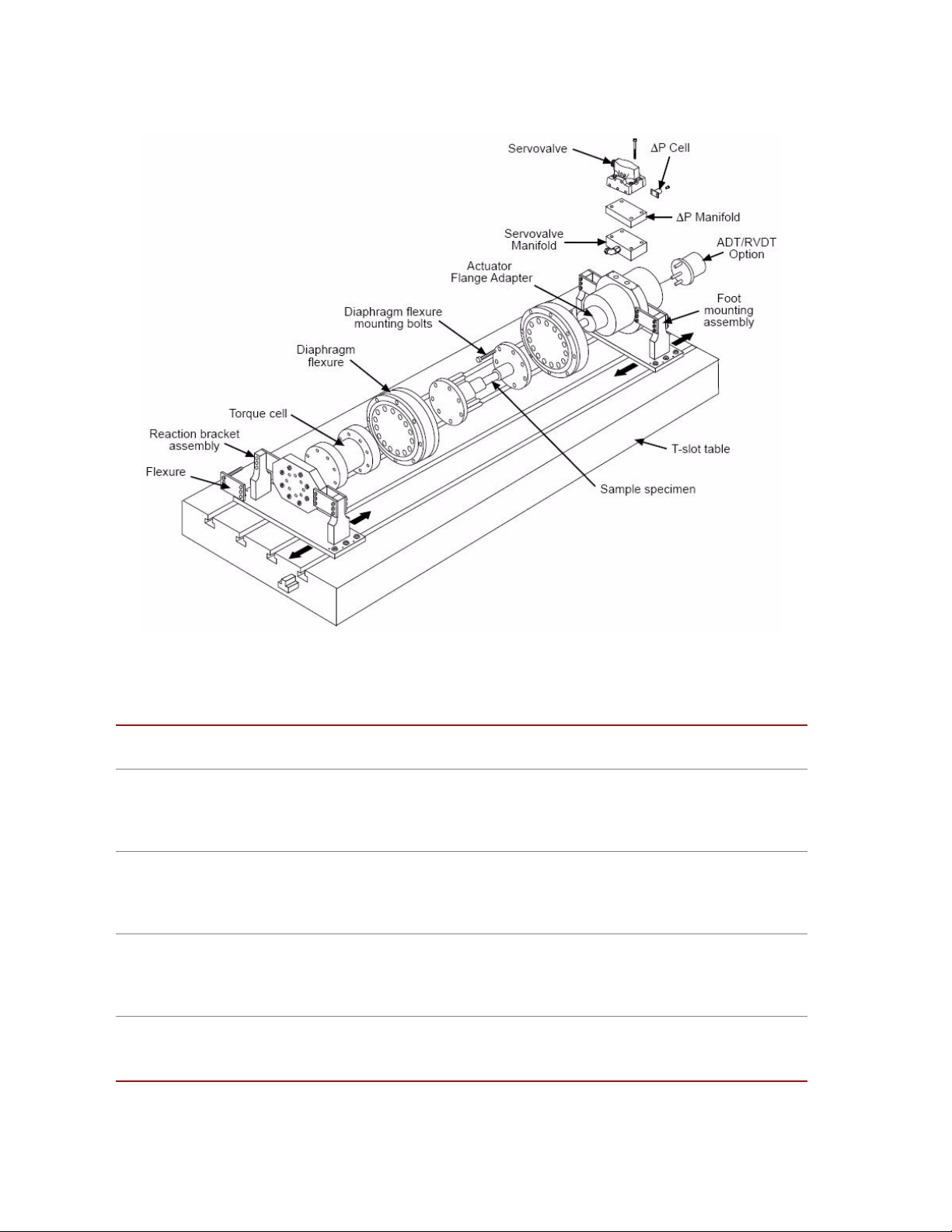
Series 215 Rotary Actuator
The preceding figure shows a Series 215 Rotary Actuator with an attached
Servovalve/Servovalve manifold, flange adapter, and foot mounting assembly.
Optional Equipment
A variety of options are available for the Series 215 Rotary Actuators. The
following figure and table show a test system containing a rotary actuator and the
available optional components.
Series 215 Rotary Actuator Product Manual Introduction
13
Page 14
Optional Equipment
Rotary Actuator Test System with Optional Equipment
Optional Equipment for Series 215 Rotary Actuators
PTION FUNCTION
O
Reaction base plate or
T-slot table
A reaction base plate or T-slot table is used with the rotary actuator for two
purposes; (1) it provides a mounting surface for the actuator and drive train
components; (2) it provides a structure which can react the large forces generated
by the rotary actuator.
Flange adapter
The flange adapter (located behind the diaphragm flexure in the photograph) is
secured to the actuator rotor shaft by a split flange clamp assembly. It provides a
coupling surface between the actuator and specimen adapter plate or diaphragm
flexure.
Diaphragm flexures
Diaphragm flexures should be used at both ends of the specimen if large axial and
angular deflections are generated during testing. If reaction forces exceed stated
actuator operating limits, diaphragm flexures help reduce the thrust and side loads
experienced by the actuator.
Reaction bracket
The reaction bracket attaches securely to the reaction base plate or T-slot table and
provides a mounting surface for the torque cell. Each reaction bracket is designed
to restrain a specific model torque cell.
14
Introduction
Series 215 Rotary Actuator Product Manual
Page 15
Torque cell
Closed-Loop Rotary Actuator Systems
Optional Equipment for Series 215 Rotary Actuators (Continued)
A torque cell provides a precise electrical feedback signal that is proportional to
the torque applied to the specimen. For more information on MTS torque cells,
refer to the appropriate MTS product specification.
ADT
An angular displacement transducer (ADT) connected to the rear shaft of the
actuator produces a DC electrical signal that is proportional to the angular position
of the actuator. Rotation of the actuator will generate a feedback signal
(0 V DC to ±10 V DC) from the ADT to the transducer conditioner. Rotation is
continuous with no reactive torque induced. The ADT is a precision differential
capacitor coupled to a solid state oscillator, demodulator, and amplifier to yield
DC input - DC output performance.
RVDT
A rotary variable differential transformer (RVDT) attached to the rear shaft of the
actuator provides an AC feedback signal proportional to the angular position of
the actuator. As the actuator rotates, a feedback signal is sent to the transducer
conditioner. An RVDT converts a mechanical angular displacement into an
electrical output by means of an electrical input carrier. It consists of a rotor
assembly to which the mechanical input is applied, and a stator assembly in which
the windings are contained.
Differential pressure
cell
The differential pressure (∆P) cell is a single-unit, dual port, bonded strain gage
pressure sensor. Depending on the specific application, the ∆P cell is used to
stabilize or control actuator force output. The ∆P cell (located beneath the
servovalve) provides a feedback signal to a controller monitoring fluid pressure
within the actuator housing. For more information on MTS ∆P cells, refer to the
appropriate MTS product specification.
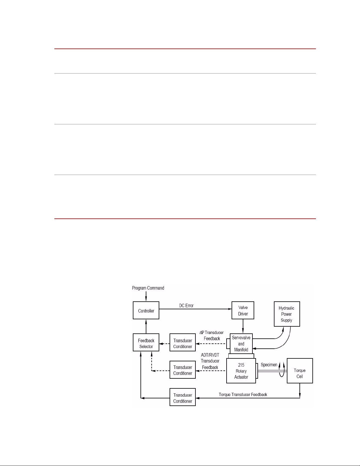
Closed-Loop Rotary Actuator Systems
In a closed-loop control system containing a rotary actuator, a command signal
sent to the actuator servovalve is compared to a feedback signal received from an
actuator transducer. The following figure shows a block diagram of the major
components in a typical rotary actuator closed-loop control system.
Block Diagram of a Testing System Using a Rotary Actuator
Series 215 Rotary Actuator Product Manual Introduction
15
Page 16

Actuator Specifications
Actuator Specifications
Series 215 Rotary Actuator Ratings by Model
M
ODEL RATED
TORQUE*
As the block diagram shows, a program command signal is input to the
controller. The command signal is compared to the feedback signal from one of
the actuator transducers. If the command signal equals the feedback signal from
the transducer conditioner, no DC error is present and the valve driver circuit
produces little or no servovalve control signal. If the command signal does not
equal the feedback signal, a DC error signal is sent to the valve driver circuit.
The valve driver circuit uses this signal to generate a servovalve control signal.
The servovalve control signal causes the servovalve spool to open in a direction
and by an amount necessary to direct a regulated flow of hydraulic fluid to the
actuator’s pressure or return ports. The actuator moves in response to the flow of
hydraulic fluid. The constant feedback of the closed-loop system enables the
controller to maintain precise control of actuator torque or movement.
Series 215 Rotary Actuators are available in six models. This section lists
specifications for both the Series 215 Actuator and its options.
ISPLACEMENT THRUST LOAD
D
Q (MAXIMUM)
IDE
S
LOAD†
P (M
AXIMUM)
ENDING
B
M
OMENT
M (MAXIMUM)
lbf·in. N·m in.3/rad cm3/rad lbf kN lbf kN lbf·in. N·m
215.32 2000 226 0.80 13.1 750 3.3 1500 6.67 3600 405
215.35 5000 565 1.9 31.1 750 3.3 3500 15.57 15,400 1732
215.41 10,000 1130 3.7 60.6 750 3.3 3500 15.57 15,400 1732
215.42 20,000 2260 7.2 117.9 750 3.3 3500 15.57 17,300 1946
215.45 50,000 5650 19.0 311.3 1200 5.3 5700 25.36 43,000 4837
215.51 100,000 11,300 38.0 622.7 1200 5.3 6500 28.92 50,000 5625
* Actuator is designed for cyclic use at rated torque: rated at maximum differential pressure at 21 MPa
(3000 psi).
† P and M are interdependent: if P is at maximum, M must be zero; if P = 75% of maximum, M may
be up to 25% of its maximum value.
‡ If these values are to be exceeded, additional internal or external cushions are required; contact
MTS.
§ w = rotational velocity in rad/sec and J or I = rotational inertia in lbm-in.
from rotary actuator, flange, flexure, and 1/2 of test specimen (lbm = pounds mass).
¶ Does not include flange adapter.
2
or kg-m2 including inertias
16
Introduction
Series 215 Rotary Actuator Product Manual
Page 17

Series 215 Rotary Actuator Ratings by Model
w
260
J
---------=
w
4.4
I
-------=
w
305
J
---------=
w
5.2
I
-------=
w
385
J
---------=
w
6.6
I
-------=
w
840
J
---------=
w
14.4
I
----------=
w
970
J
---------=
w
16.6
I
----------=
w
1525
J
------------=
w
26.1
I
----------=
M
ODEL MAX VELOCITY
CUSHION LIMITATION‡
Actuator Specifications
OTARY ACTUATOR ROTATIONAL INERTIA¶
R
U.S.
Customary
rad/sec
215.32 11.67 0.00342
215.35 18.54 0.00544
215.41 20.23 0.00594
215.42 29.04 0.00852
215.45 171 0.0500
215.51 284 0.0831
* Actuator is designed for cyclic use at rated torque: rated at maximum differential
pressure at 21 MPa (3000 psi).
† P and M are interdependent: if P is at maximum, M must be zero; if P = 75% of
maximum, M may be up to 25% of its maximum value.
‡ If these values are to be exceeded, additional internal or external cushions are
required, contact MTS.
§ w = rotational velocity in rad/sec and J or I = rotational inertia in lbm-in.2 or kg-m2
including inertias from rotary actuator, flange, flexure, and 1/2 of test specimen (lbm =
pounds mass).
¶ Does not include flange adapter.
SI Metric
rad/sec
lbm-in.
J
2
kg-m
I
2
Series 215 Rotary Actuator Product Manual Introduction
17
Page 18
Actuator Specifications
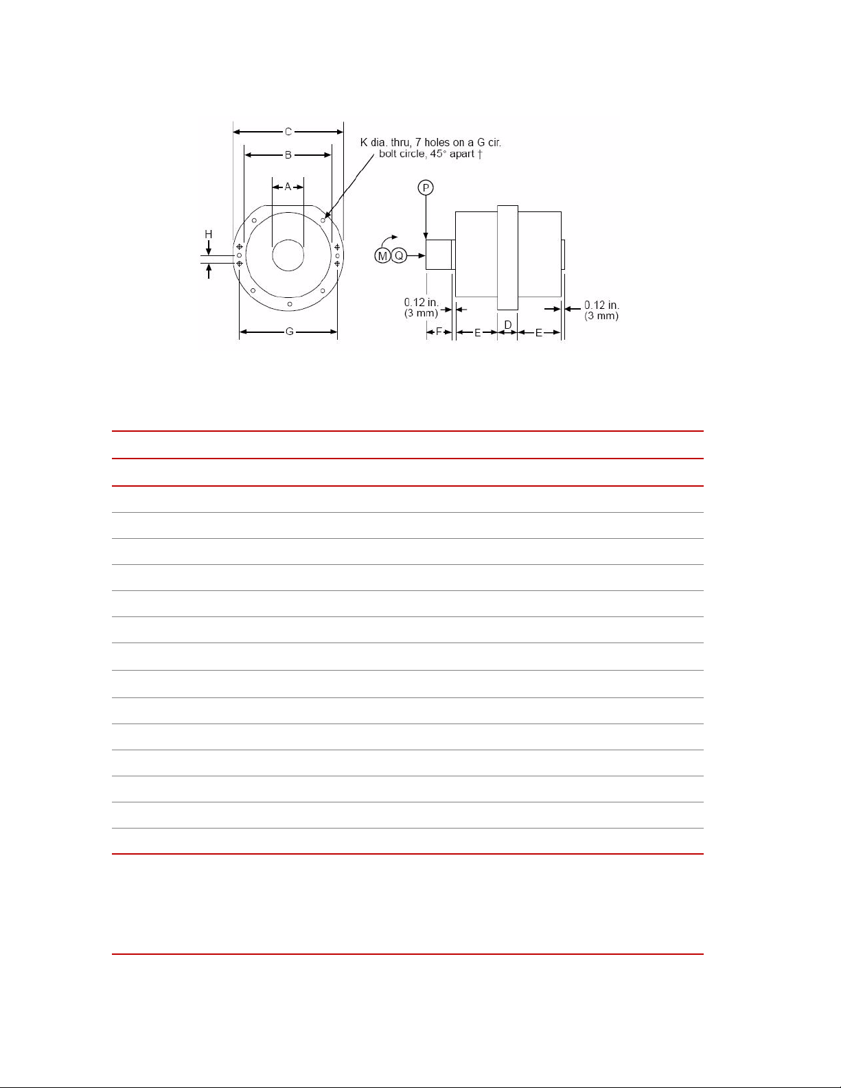
ABC DE
Actuator Dimensional Drawing
Actuator Dimensions and Weights
M
ODEL IN. MM IN. MM IN. MM IN. MM IN. MM
215.32 1.50 38.1 7.875 200.0 10.00 254 1.175 29.8 3.130 79.5
215.35 2.251 57.1 7.875 200.0 10.00 254 2.275 57.8 3.130 79.5
215.41 2.251 57.1 7.875 200.0 10.00 254 2.275 57.8 3.130 79.5
215.42 2.251 57.1 7.875 200.0 10.00 254 3.275 83.2 3.130 79.5
215.45 3.751 95.3 9.875 250.8 12.25 311 2.775 74.5 4.137 105.1
215.51 3.751 95.3 9.875 250.8 12.25 311 5.553 141.0 4.137 105.1
FGH KWEIGHT
MODEL IN. MM IN. MM IN. MM IN. MM LB KG
215.32 2.50 63.5 9.000 228.6 1.000 25.4 0.406 10.3 100 45
215.35 2.50 63.5 9.000 228.6 1.000 25.4 0.406 10.3 130 59
215.41 2.50 63.5 9.000 228.6 1.000 25.4 0.406 10.3 130 59
215.42 2.99 75.9 9.000 228.6 1.000 25.4 0.406 10.3 150 70
215.45 3.49* 88.6* 11.000 279.4 1.000 25.4 0.656 16.7 270 125
215.51 5.12* 130.0* 11.000 279.4 1.000† 25.4† 0.656 16.7 365 165
* Contains a 3.0 mm (0.12 in.) shoulder that is 0.25 mm (0.01 in.) larger in diameter than Dimension
'A'.
† 215.51 pattern has more bolt holes, not evenly spaced.
Dimensions and weights are subject to change without notice. Contact MTS for dimensions and weights crit-
ical to your needs.
18
Introduction
Series 215 Rotary Actuator Product Manual
Page 19

Options Specifications
Foot Mounting The foot mounting option is used for easy attachment of the actuator to a reaction
Options Specifications
Specifications for the most common options available for use with the Series 215
Rotary Actuators are described below.
base and also provides some flexure capability.
Series 215 Rotary Actuator Product Manual Introduction
19
Page 20

Options Specifications
Foot Mounting Dimensions and Ratings
M
ODEL ABCD
IN. MM IN. MM IN. MM IN. MM
215.32 6.25 158.8 0.75 19 5.00 127 17.00 432
215.35 6.25 158.8 0.75 19 5.00 127 17.00 432
215.41 6.50 166.4 1.00 25 5.00 127 19.50 495
215.42 6.50 166.4 1.00 25 5.00 127 19.50 495
215.45 7.75 196.8 1.50 38 6.00 152 22.00 559
215.51 7.75 196.8 1.50 38 6.00 152 22.00 559
MODEL EFGTHRUST LOAD*
IN. MM IN. MM IN. MM LBF N
215.32 12.00 304.8 3.75 92.3 0.781 19.8 100 445
215.35 12.00 304.8 3.75 92.3 0.781 19.8 100 445
H (M
AXIMUM)
215.41 18.00 457.2 3.50 88.9 0.781 19.8 150 670
215.42 18.00 457.2 3.50 88.9 0.781 19.8 150 670
215.45 18.00 457.2 4.00 101.6 0.781 19.8 500 2200
215.51 18.00 457.2 4.00 101.6 0.781 19.8 500 2200
MODEL THRUST
D
EFLECTION
I (MAXIMUM)
IN. MM LBF-IN.N-MRAD LBF-IN.N-M RAD
215.32 0.03 0.76 200 22 0.004 4500 508 0.003
215.35 0.03 0.76 200 22 0.004 4500 508 0.003
215.41 0.07 1.8 400 45 0.008 9000 1000 0.003
215.42 0.07 1.8 400 45 0.008 9000 1000 0.003
215.45 0.06 1.5 2000 225 0.006 20,000 2260 0.0008
215.51 0.06 1.5 2000 225 0.006 35,000 3960 0.0004
* Thrust load (H) and bending moments (J and L) are interdependent. H ratings assume J =
0 and L = 0. J and L ratings assume H = 0. Ratings must be decreased in proportion to other
loads present, for example, if H = 75% of rating, J and L must not total 25% of rating.
Dimensions and ratings are subject to change without notice. Contact MTS for verification of
critical dimensions and ratings.
ORIZONTAL
H
B
ENDING
M
OMENT*
J (M
AXIMUM)
A
NGULAR
D
EFLECTION
K
ERTICAL*
V
M
OMENT L
(M
AXIMUM)
BENDING
A
NGULAR
DEFLECTION
M
20
Introduction
Series 215 Rotary Actuator Product Manual
Page 21
Options Specifications
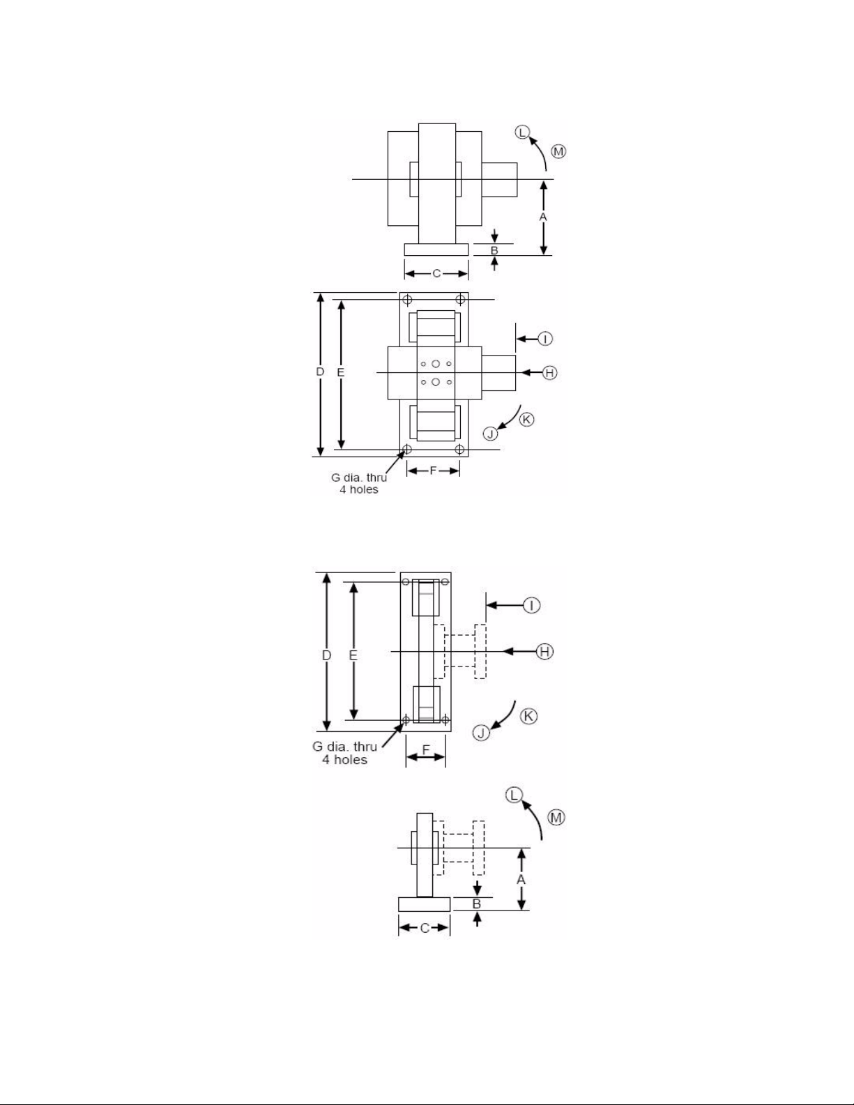
Foot Mounting Specification Drawing
Reaction Bracket Specification Drawing
Series 215 Rotary Actuator Product Manual Introduction
21
Page 22

Reaction Brackets
Reaction Brackets
Reaction brackets provide a torsionally rigid connection between the torque cell
and the reaction base. Brackets provide some flexural capability and readily
accept MTS torque cells.
Reaction Bracket Dimensions and Ratings
M
ODEL ABCD E F
IN. MM IN. MM IN. MM IN. MM IN. MM IN. MM
215.32 6.25 158.8 0.75 19 5.00 127 17.00 432 12.00 304.8 3.75 92.3
215.35 6.25 158.8 0.75 19 5.00 127 17.00 432 12.00 304.8 3.75 92.3
215.41 6.50 166.4 1.00 25 5.00 127 19.50 495 18.00 457.2 3.50 88.9
215.42 6.50 166.4 1.00 25 5.00 127 19.50 495 18.00 457.2 3.50 88.9
215.45 7.75 196.8 1.50 38 6.00 152 22.00 559 18.00 457.2 4.00 101.6
215.51 7.75 196.8 1.50 38 6.00 152 22.00 559 18.00 457.2 4.00 101.6
MODEL GTHRUST LOAD*
H (M
AXIMUM)
IN. MM LBF N IN. MM LBF·IN
HRUST
T
D
EFLECTION
I (MAXIMUM)
ORIZONTAL
H
B
ENDING
M
OMENT*
J (M
AXIMUM)
A
NGULAR
D
EFLECTION
K
ERTICAL*
V
B
M
(M
M RAD LBF·IN.N·M RAD
N·
ENDING
OMENT L
AXIMUM)
A
NGULAR
D
EFLECTI
ON
M
.
215.32 0.781 19.8 100 445 0.03 0.76 200 22 0.004 3500 395 0.003
215.35 0.781 19.8 100 445 0.03 0.76 200 22 0.004 3500 395 0.003
215.41 0.781 19.8 150 670 0.07 1.8 400 45 0.008 9000 1000 0.003
215.42 0.781 19.8 150 670 0.07 1.8 400 45 0.008 9000 1000 0.003
215.45 0.781 19.8 500 2200 0.06 1.5 2000 225 0.006 20,0002260 0.0012
215.51 0.781 19.8 500 2200 0.06 1.5 2000 225 0.006 35,0003960 0.0012
* Thrust load (H) and bending moments (J and L) are interdependent. H ratings assume J = 0 and L = 0.
J and L ratings assume H = 0. Ratings must be decreased in proportion to other loads present, for
example, if H = 75% of rating, J and L must not total 25% of rating.
Dimensions and ratings are subject to change without notice. Contact MTS for verification of dimensions
and ratings critical to your needs.
22
Introduction
Series 215 Rotary Actuator Product Manual
Page 23

Reaction Bases
Reaction bases are constructed of heavy-duty steel and designed for high
torsional stiffness. They readily accept MTS rotary actuators and reaction
brackets. When used with MTS reaction brackets and foot mounting options, the
stiffness/flexural capability is adequate to prevent excessive actuator side loads.
(However, a review of thrust loads should be made.) When purchased as a
system, the specimen length is fully adjustable (within the specified limits)
without requiring realignment of the actuator and reaction bracket. If required,
legs are available to raise the bases to any specified height.
Reaction Base Dimensions and Ratings
M
ODEL LENGTH§WIDTH HEIGHT*MAXIMUM SPACE†
IN. MM IN. MM IN. MM IN. MM
Reaction Bases
215.32
215.35
215.41
215.42
215.45
215.51
ODEL WEIGHT TORSIONAL STIFFNESS‡
M
215.32
215.35
215.41
215.42
215.45
215.51
45 1143 15 380 4.7 120 28.50 724
45 1143 15 380 4.7 120 28.00 711
54 1370 22 560 5.7 144 33.50 851
54 1370 22 560 5.7 144 29.75 756
60 1525 22 560 20 508 34.50 876
60 1525 22 560 20 508 30.25 768
LB KG LBF·IN./RAD N·M/RAD
375 170
375 170
800 363
800 363
1125 510
1125 510
55 x 10
55 x 10
122 x 10
122 x 10
742 x 10
742 x 10
6
6
6
6
6
6
6.2 x 10
6.2 x 10
13.7 x 10
13.7 x 10
83.8 x 10
83.8 x 10
6
6
6
6
6
6
* Without legs.
§ Longer bases available on request.
† Maximum space between mounting surfaces of actuator output flange and torque cell (with the
MTS reaction bracket supporting the torque cell).
‡ Torsional stiffness over entire length. Stiffness increases proportionately as the actuator and
reaction bracket are moved toward each other.
Dimensions and ratings are subject to change without notice. Contact MTS for verification of
dimensions and ratings critical to your needs.
Series 215 Rotary Actuator Product Manual Introduction
23
Page 24

Diaphragm Flexures
Diaphragm Flexures
As described in the “Test Setup Considerations” section, one or two diaphragm
flexures are used when large thrust and side loads are encountered on test setups
having both the rotary actuator and the reaction bracket rigidly mounted to the
reaction base. The flange adapter option is required to attach the diaphragm
flexure to the actuator. The flexure attaches readily to torque cells. The rotational
inertia of the diaphragm flexure must be included when determining the actuator
performance.
Diaphragm Flexure Dimensions and Ratings
M
ODEL AB C DE F G
IN. MM IN. MM IN. MM THREAD
S
IZE
215.32 4.00 101 9.75 248 2.00 51 5/16-18 0.88 22 0.344 8.7 0.41 10
215.35 5.00 127 9.75 248 2.00 51 3/8-16 0.86 22 0.406 10.3 0.40 10
215.41 5.00 127 12.25 311 2.03 52 3/8-16 0.89 23 0.406 10.3 0.42 11
215.42 8.00 203 12.25 311 2.93 74 5/8-11 1.33 34 0.656 16.6 0.39 10
215.45 8.00 203 15.25 387 2.99 76 5/8-11 1.36 35 0.656 16.6 0.42 11
215.51 9.75 248 15.25 387 3.49 89 3/4-10 1.62 41 0.781 19.8 0.42 11
MODEL HTHRUST LOAD
J (MAXIMUM)
IN
. MM LBF N IN. MM LBF·IN.N·M RAD
215.32 3.25 82.55 100 450 0.15 3.81 100 11.3 0.028 85 0.0249
215.35 4.25 107.95 100 450 0.15 3.81 100 11.3 0.025 95 0.0278
215.41 4.25 107.95 150 670 0.15 3.81 100 11.3 0.025 210 0.0614
EFLECTION
D
K (MAXIMUM)
. MM IN. MM IN. MM
IN
ENDING
B
M
OMENT
L (MAXIMUM)
NGULAR
A
DEFLECT
M
OTATIONAL
R
INERTIA
·IN.
LBM
2
KG·M
2
215.42 6.50 165.10 150 670 0.17 4.32 300 33.9 0.015 460 0.135
215.45 6.50 165.10 500 2200 0.25 3.81 400 45.2 0.015 960 0.281
215.51 8.00 203.20 500 2200 0.15 3.81 400 45.2 0.015 1400 0.410
Dimensions and ratings are subject to change without notice. Contact MTS for verification of
dimensions and ratings critical to your needs.
24
Introduction
Series 215 Rotary Actuator Product Manual
Page 25

Flange Adapters
Flange Adapters
Diaphragm Flexure Specification Drawing
A flange adapter may be used to mount the specimen to the actuator. Adapter
mounting position is adjustable. The actuator shaft may extend beyond the
adapter, be flush with it, or be recessed into it. Diameter A may be used as a
shallow pilot.
Flange Adapter Dimensions and Inertia
M
ODEL ABCD
IN. MM IN. MM IN. MM IN. MM
215.32 2.2511 57.2 4.00 102 2.25 57 2.99 75.9
215.32 2.2511 57.2 5.00 127 2.25 57 2.99 75.9
215.41 2.2511 57.2 5.00 127 2.00 51 2.99 75.9
215.42 2.2511 57.2 8.00 203 2.00 51 2.99 75.9
215.45 3.7400 95.0 8.00 203 3.25 83 3.68 93.5
215.51 3.7400 95.0 9.75 248 4.88 124 5.31 134.9
Series 215 Rotary Actuator Product Manual Introduction
25
Page 26

Flange Adapters
ODEL EF G ROTATIONAL INERTIA
M
THREAD
IN
. MM IN. MM LBM·IN.
2
KG·M
2
SIZE
215.32 5/16-18 0.63 16.0 3.25 82.5 14.4 0.00421
215.32 3/8-16 0.75 19.1 4.25 107.9 21.8 0.00639
215.41 3/8-16 0.75 19.1 4.25 107.9 21.8 0.00639
215.42 5/8-11 0.75 19.1 6.50 165.1 208 0.0608
215.45 5/8-11 1.25 31.8 6.50 165.1 273 0.0799
215.51 3/4-10 1.50 38.1 8.00 203.2 737 0.216
Dimensions are subject to change without notice. Contact MTS for verification of
dimensions critical to your needs.
26
Introduction
Flange Adapter Dimension Drawing
Series 215 Rotary Actuator Product Manual
Page 27

Safety Information
4
(27.6 MPa).
2
4
Hazard Placard Placement
Hazard placards contain specific safety information and are affixed directly to the
system so they are plainly visible.
Each placard describes a system-related hazard. When possible, international
symbols (icons) are used to graphically indicate the type of hazard and the
placard label indicates its severity. In some instances, the placard may contain
text that describes the hazard, the potential result if the hazard is ignored, and
general instructions about how to avoid the hazard.
The following labels and icons may be found on an actuator.
L
ABEL DESCRIPTION
Hazard Placard Placement
Part #46-140-101
Part #46-140-201
WA RN I NG
Hydraulic pressure above 3000 psi can rupture
components. Can cause severe personal injury
or damage to equipment.
Do not exceed 3000 psi (20.7 MPa).
Read instructions before operating or
servicing.
WA RN I NG
Hydraulic pressure above 4000 psi can rupture
components. Can cause severe personal injury
or damage to equipment.
Do not exceed 4000 psi (27.6 MPa).
Read instructions before operating or
servicing.
Series 215 Rotary Actuator Product Manual Safety Information
27
Page 28

Hazard Placard Placement
L
ABEL DESCRIPTION
CAUTION
High drain pressure can cause rod seal damage
and hydraulic oil leakage.
Remove drain line shipping cap and connect
drain hose before operating.
Part # 045-283-501
Attached mass warning.
Do not exceed maximum attached mass.
Part # 057-230-041
Part # 700-004-198
Hydraulic Actuator ID tag lists the following:
• Model number
• Serial number
• Assembly number/Rev
• Force
• Effective Area
• Static Stroke
• Dynamic Stroke
• Hydrostatic/Non-Hydrostatic
• Maximum attached mass
Safety Information
28
Series 215 Rotary Actuator Product Manual
Page 29

L
ABEL DESCRIPTION
Hydraulic Actuator ID tag lists the following:
• Model number
• Serial number
• Assembly number/Rev
• Force
• Effective Area
• Static Stroke
Hazard Placard Placement
Part # 037-588-801
Part # 57-237-711
Part # 57-238-5xx
• Dynamic Stroke
• Hydrostatic/Non-Hydrostatic
Pressure icon.
Can be used alone, or in conjunction with
pressure rating label (Part # 57-238-5xx).
Pressure rating. Actual rating listed on this
label will vary. This label is used in
conjunction with the Pressure icon (Part #
57237711). Located directly beneath pressure
icon on actuator.
Series 215 Rotary Actuator Product Manual Safety Information
29
Page 30

Hazard Placard Placement
Safety Information
30
Series 215 Rotary Actuator Product Manual
Page 31

Installation
This section describes the procedures for installing the Series 215 Rotary
Actuator and optional equipment onto a base plate or T-slot table. It also includes
instructions for aligning the components of the rotary actuator test system after
they have been installed or moved.
Though the Series 215 Rotary Actuator can be installed onto any suitable base
plate or T-slot table that conforms to the specifications listed in the Diaphragm
Flexure Dimensions and Ratings table, these instructions assume that an MTS
supplied base plate or T-slot table will be used.
Typical Test System Configuration (Using T-slot Table)
Series 215 Rotary Actuator Product Manual Installation
31
Page 32

Actuator Installation
Actuator Installation
Typically, the Series 215 Rotary Actuator is first bolted to a foot mounting
assembly, then positioned on a base plate or T-slot table and secured with lightly
lubricated mounting bolts. The foot mounting dimensions and ratings must match
the actuator in use. After completing the alignment of force train components,
torque the bolts to the correct values.
Actuator Mounting Bolt Torque Values
M
ODEL ACTUATOR ASSEMBLY TO FOOT
M
OUNTING
·FT N·MLBF·FT N·M
LBF
215.32, 215.35 35 47 150 204
FOOT MOUNTING TO BASE PLATE OR T-SLOT
T
ABLE
215.41, 215.42
215.45, 215.51
80 110 150 204
Reaction Bracket and Torque Cell Installation
The reaction bracket should be positioned at the opposite end of the base plate or
T-slot table from the actuator. Ensure that it is oriented with the smooth vertical
surface facing the actuator.
Lightly lubricate the reaction bracket mounting bolts and hand-tighten them to
secure the position of the reaction bracket. The reaction bracket mounting bolts
should not be fully tightened until the force train components are aligned. Refer
to the appropriate table for the reaction bracket force ratings and the torque
values used when installing the reaction bracket and torque cell.
In most cases the selected torque cell bolts directly to the surface of the reaction
bracket. When possible, the side of the torque cell that attaches to the center
collar should be bolted to the reaction bracket. This configuration will cause the
least movement of the torque cell electrical cable. The torque cell and reaction
bracket should be bolted together with the correct torque value. It may be
necessary to temporarily tighten the reaction bracket mounting bolts to keep it
from moving while the torque cell is bolted in place.
32
Installation
Series 215 Rotary Actuator Product Manual
Page 33

Reaction Bracket and Torque Cell Installation
MTS Base Plate and Reaction Bracket
Reaction Bracket Ratings and Mounting Bolt Torque Value
M
ODEL REACTION BRACKET RATING TORQUE CELL TO REACTION
B
RACKET TORQUE VALUE
·FT.N·MLBF·FT.N·MLBF·FT.N·M
LBF
215.32 2000 0.226 18 24.0 150 204
215.35 5000 0.560 35 47.0 150 204
215.41 10,000 1.130 35 47.0 150 204
215.42 20,000 2.260 170 230.0 150 204
215.45 50,000 5.650 170 230.0 150 204
215.51 100,000 11.300 280 380.0 150 204
REACTION BRACKET TO BASE OR TS
LOT TABLE TORQUE VALUE
Series 215 Rotary Actuator Product Manual Installation
33
Page 34

Diaphragm Flexure Installation
Diaphragm Flexure Installation
Depending upon user requirements, the end of the actuator rotor shaft can extend
beyond the flange, be flush with it, or be recessed into the flange adapter to allow
the use of the inside diameter as a pilot diameter.
Diaphragm flexures are used to reduce the potentially damaging effects of large
axial and lateral deflections of the actuator rotor shaft. Perform the necessary
calculations for determining whether or not diaphragm flexures are required by
the specific test system.
Mount the flexure(s) to either the flange adapter or the torque cell.
The following table lists the flexure ratings and mounting bolt torques for the
available flexure diaphragms.
Flange Adapter and Diaphragm Flexure Rating
FLANGE AND DIAPHRAGM FLEXURE RATING MOUNTING BOLT TORQUE
M
ODEL
·N.N·MLBF·IN.N·M
LBF
215.32 2000 226 18 24
215.35 5000 565 35 47
215.41 10,000 1130 35 47
215.42 20,000 2260 170 230
215.45 50,000 5650 170 230
215.51 100,000 11,300 280 380
Aligning Force Train Components
After the actuator, reaction bracket, and torque cell have been positioned on the
base plate or T-slot table, they must be aligned. The goal of the alignment process
is to ensure that the actuator and torque cell share the same centerline.
If the test system utilizes a base plate supplied by MTS, the actuator and reaction
bracket will have been pre-aligned at the factory. The combination of an MTS
base plate and reaction bracket enables the operator to easily move the reaction
bracket/torque cell assembly and simplifies the alignment procedure.
If the test system does not utilize an MTS base plate or T-slot table, the torque
cell has been separated from the reaction bracket, or the actuator has been moved,
then the “Component Centerline Alignment Procedure” must be performed in
order to ensure proper alignment of the components of the test system. If the
reaction bracket, torque cell, and actuator have not been moved and were
properly aligned when installed, then it is not necessary to perform the alignment
procedures.
34
Installation
The diaphragm flexure assemblies are self-centering.
Series 215 Rotary Actuator Product Manual
Page 35

Note In each of the following procedures the base plate or T-slot table must be
flat to within 0.015 mm/m (0.002 in./ft).
Component Alignment on an MTS Base Plate
Rotary actuator testing systems equipped with an MTS base plate and reaction
bracket combination are pre-aligned. The following procedure describes the
alignment process used when you wish to increase or decrease the distance
between the actuator and the torque cell.
Note If the actuator has been moved or the torque cell has been separated
from the reaction bracket, the “Component Centerline Alignment
Procedure” must be completed before attempting this procedure.
1. To move the reaction bracket and torque cell assembly, loosen the lateral
clamping bolts located on the left side of the reaction bracket.
2. Loosen the vertical clamping bolts on the reaction bracket.
3. Slide the reaction bracket and torque cell assembly to the desired position.
4. Tighten the lateral clamping bolts on the left side of the reaction bracket to
assure alignment.
Component Alignment on an MTS Base Plate
5. To secure the reaction bracket and torque cell assembly, lubricate and
tighten each of the lateral clamping bolts to 3.9 N·m (35 lbf·in.).
6. Lubricate and tighten each of the vertical clamping bolts to 84.7 N·m (750
lbf·in.). Alignment is complete.
Component Centerline Alignment
If the test system does not utilize an MTS base plate or T-slot table, or the torque
cell has been separated from the reaction bracket, or the actuator has been moved,
then this procedure must be performed in order to ensure proper alignment of the
components of the test system. In each of the steps, it is assumed that the bolts
used to install the actuator and reaction bracket to the base plate or T-slot table
are hand tight unless otherwise specified.
The purpose of this procedure is to ensure that the actuator and torque cell share
the same centerline. The procedure is composed of three groups of steps covering
the following operations:
• Adjusting actuator and torque cell centerline height,
• Adjusting actuator and torque cell concentricity, and
• Adjusting for actuator and torque cell centerline angularity.
Adjusting Actuator and Torque Cell Centerline Height
This procedure describes the steps necessary to adjust the centerline height of the
torque cell with respect to the actuator. The procedure requires a dial indicator,
magnetic V-block, extension rod, and clamps.
1. Attach a dial indicator to the actuator rotor shaft using a magnetic V-block
as the base.
Series 215 Rotary Actuator Product Manual Installation
35
Page 36

Adjusting Actuator and Torque Cell Concentricity
2. Rotate the V-block around the rotor shaft circumference while
simultaneously reading the pilot diameter runout on the face of the torque
cell flange. Check the reading at top and bottom positions.
A. Variation between the actuator reading and the torque cell flange face
must differ by less than 0.0508 mm (0.002 in.).
B. Height adjustments are made by loosening and repositioning the torque
cell. When the proper position has been achieved, re-tighten the torque
cell mounting bolts to the appropriate torque values.
3. Repeat Steps 1 and 2 to ensure that the adjustment was not altered when the
torque cell was re-torqued.
Adjusting Actuator and Torque Cell Concentricity
While centerline heights may be identical and parallel to the base plate or T-slot
table mounting surface, the actuator and torque cell can be eccentric in a lateral
direction. There are two ways to correct for actuator/torque cell eccentricity. The
most appropriate method depends on the type of specimen to be tested. Both
methods are listed below.
Rigid specimen If the current test application makes use of a rigid specimen, then the specimen
itself can be used to facilitate the alignment process. Because the presumed goal
of the alignment process is to mount the specimen without exerting any
unintentional forces upon it, it may be simplest to loosen the bolts securing the
reaction bracket to the table and then place the specimen in position.
Flexible or fragile
specimen
When installing the mounting bolts, ensure that there are no gaps between the
specimen, flexures, and torque cell. Only after checking that both ends of the
specimen contact the mounting surfaces should the mounting bolts be torqued.
This technique allows the specimen configuration to control the “at rest” position
of the reaction bracket. Once the specimen is securely positioned, the reaction
bracket bolts may be torqued to the proper value. Do not use the mounting bolts
to pull
the reaction bracket into position.
If the current test application uses a flexible or fragile specimen, then the
following procedure must be used to correct for actuator/torque cell eccentricity.
1. Attach a dial indicator to the actuator rotor shaft using a magnetic V-block
for the base.
2. Rotate the V-block around the rotor shaft circumference while
simultaneously reading the pilot diameter runout on the torque cell flange.
3. Adjust the torque cell position for an acceptable level of eccentricity by
loosening the reaction bracket. The acceptable level of eccentricity is
determined by the test requirements.
4. After positioning the torque cell, re-tighten the mounting bolts to the
appropriate torque values.
5. Recheck the centerline height and adjust as required.
36
Installation
Series 215 Rotary Actuator Product Manual
Page 37

Adjusting Actuator and Torque Cell Centerline
Adjusting Actuator and Torque Cell Centerline Angularity
The final alignment procedure adjusts for centerline angularity deviations
between the actuator rotor shaft and the torque cell flange face.
Do not apply hydraulic pressure to the system unless the servovalve command
(DC error) has been zeroed.
If the servovalve command (DC error) does not equal zero when hydraulic
pressure is applied to the system, equipment damage or personal injury can
result.
Always ensure that the DC error is zero before applying hydraulic pressure to the
system.
1. Adjust the system controller for zero DC error and apply system hydraulic
pressure according to applicable system procedures.
2. Attach a dial indicator to the actuator rotor shaft using a magnetic V-block
for the base. Set the dial indicator to read the runout of the torque cell flange
face, outside the bolt circle area.
3. Use the Set Point control on the controller to rotate the actuator rotor shaft
while simultaneously reading the indication from the face of the torque cell
flange.
4. To obtain a reading over a wider range of motion, reposition the V-block on
the opposite side of the actuator rotor shaft and repeat Step 3.
5. Adjust the torque cell position for an acceptable level of angularity by
loosening and moving the reaction bracket. The acceptable level of
angularity is determined by the test requirements.
6. After positioning the torque cell, re-tighten the reaction bracket mounting
bolts to the appropriate torque.
7. Turn off system hydraulic pressure.
8. Repeat the “Actuator and Torque Cell Centerline Height” and “Actuator and
Torque Cell Concentricity” procedures to ensure that all measurements
conform to the requirements of the test.
Series 215 Rotary Actuator Product Manual Installation
37
Page 38

Adjusting Actuator and Torque Cell Centerline
38
Installation
Series 215 Rotary Actuator Product Manual
Page 39

Operation
CAUTION
Thrust and Side Load Characteristics
This section discusses the calculations and precautions that must be considered in
order to produce accurate test results and help protect equipment and personnel.
Though some of the calculations included in this section may not be required by
specific test situations, it is recommended that you read each section and ensure
that the actuator will be operated within the limits of its thrust load, side load, and
rotational inertia ratings.
Do not exceed the thrust load, side load, or rotational inertia ratings of the
actuator.
Exceeding the thrust load, side load, or rotational inertia ratings of the
actuator can damage equipment, injure personnel, and void any warranty in
effect on the Series 215 Rotary Actuator.
Ensure that the thrust load, side load, and rotational inertia ratings for the actuator
exceed the anticipated test forces. This section contains calculations for deriving
the anticipated test forces.
Thrust and Side Load Characteristics
The thrust and side loads that may be encountered during testing are generally
the result of the following factors:
• Specimen shortening or lengthening due to torsional force
• Specimen shortening or lengthening due to temperature
• Misalignment of the test specimen when initially mounted
• Base plate or T-slot table twisting
• Permanent deformation of the specimen due to torsional force
Thrust loads The following table lists the maximum allowable thrust load (Q) that can be
applied to the actuator rotor shaft. Because thrust loads can be induced by a wide
variety of experimental conditions, this manual will not attempt to define or
predict the forces that can result from specific testing situations. If there is a
possibility that the maximum thrust load rating of the actuator will be exceeded
during testing, steps should be taken to minimize the load. One way of reducing
the effect of thrust loads on the actuator bearings is to install diaphragm flexures.
Thrust loads can have a significant effect on actuator bearings. These effects are a
function of specimen geometry, material, and temperature as shown in the
following example:
Increase the temperature of a steel shaft 25.4 mm (1 in.) in diameter and 1,270
mm (50 in.) in length by 22˚C (40˚F). The increase in specimen temperature
causes the shaft to expand by approximately 0.305 mm (0.012 in.). If the shaft is
Series 215 Rotary Actuator Product Manual Operation
39
Page 40

Definition of Useful Mathematical Terms
mounted in a force train using a 215 Rotary Actuator, the shaft expansion would
exert a resultant force of 6,000 lbs. on the actuator bearings.
To confine the resultant force to an acceptable maximum requires the addition of
diaphragm flexures to the force train. Multiplying the stiffness of the diaphragm
flexure by the amount of specimen expansion will give the thrust load imposed
on the actuator bearings.
Use the following formula to calculate the maximum thrust load applied to the
actuator bearings when using diaphragm flexures:
Flexure Stiffness (Flexure’s Maximum Thrust Deflection) = Maximum Thrust
Load
Side loads Side loads, which are normally induced by specimen misalignment or base plate
or T-slot table compliance, may be active at the same time thrust loads are active.
If the specimen is soft, such as a length of rubber hose, side loads on the actuator
are relatively small. This is because the specimen bends easily and exerts little
resistance to the deflection caused by base plate twisting. However, if the
specimen is stiffer (steel for example), the increased resistance of the specimen to
bending exerts substantial side loads on the actuator bearings and torque cell due
to the restraining characteristics of the test setup. As in the test setup for thrust
loads, diaphragm flexures can be used to reduce the side loads to a practical limit.
Note The service life of the actuator is normally reduced by significant thrust
and side loads. For this reason, the use of flexure diaphragms and a rigid
base plate is recommended even when the actuator’s thrust and side
load ratings are sufficient for the test situation.
Definition of Useful Mathematical Terms
The following terms are listed in alphabetical order and defined in both U.S.
Customary and SI Metric units of measure.
Mathematical Terms (part 1 of 3)
ERM DEFINITION TERM DEFINITION
T
a Distance from actuator's center line to
center of reaction base plate’s solid
height (mm) (in.).
β 0.333 - 0.21 (d/b) k
b Width of reaction base plate (mm) (in.). k
k2 Lateral stiffness of a solid cylindrical
specimen (kN/mm) (lbf/in.)
12 ET IL2 3
F1
F2
Angular horizontal stiffness of actuator and
reaction bracket flexures (N·m/rad) (lbf·in./
rad).
M
F1/θF1
Lateral stiffness of diaphragm flexures (lbfin./rad).
d Thickness of reaction base plate (mm)
(in.). Measurement of solid metal only.
Do not include T-slot depth.
Operation
40
=MF2/θ
L
1
Length of base plate or T-slot table subjected
to twisting (mm) (in.).
F2
Series 215 Rotary Actuator Product Manual
Page 41

Mathematical Terms (part 2 of 3)
T
ERM DEFINITION TERM DEFINITION
Definition of Useful Mathematical Terms
E
E
I
k
Μ
M
S
Modulus of elasticity of the base plate or
T-slot table, shear (N/m2) (lb/in.2)
L
2
Length of test specimen (mm) (in.). Do not
include specimen adapter plates unless their
compliance is equal to or greater than that of
the specimen.
T
Modulus of elasticity of the specimen,
tension (N/m2) (lb/in.2).
Moment of inertia for a round solid (mm
4
(in.
)
πr4/4
1
Torsional stiffness of a thin flat plate (Nm./rad) (lbf-in./rad)
L
F
Distance between flexing points of
diaphragm flexures.
4
M Bending moment on test specimen with no
)
flexures (N·m) (lbf·in.).
PL 22
M
1
Bending moment on actuator and reaction
bracket with standard flexures installed (Nm) (lbf-in.).
Es (β)bd3 /L
2
Bending moment on test specimen with
1
θ
k
F1
T Applied torque (N-m) (lbf-in.)
standard flexures or diaphragm flexures
installed (N-m) (lbf-in.).
(Standard Flexures)
(Diaphragm Flexures)
F
1
Maximum lateral bending capacity of
standard flexures (N-m) (lbf-in.)
u Distance from front bearing to specimen
(mm) (in.). Include specimen adapter plates
if they are less compliant than the specimen.
M
F
2
Maximum horizontal bending capacity of
W Load on front actuator bearing (kN) (lbf)
diaphragm flexures (N-m) (lbf-in.)
P Side load imposed on test specimen and
actuator.
∆ Centerline offset between actuator and
reaction bracket mountings due to twisting of
base plate or T-slot table (mm) (in.).
=k2k1aT1 + k2k1a2
∆ =
r Radius of test specimen (mm) (in.) q Angle of flex imposed on flexures (rad).
(Standard Flexures)
(Diaphragm Flexures)
Series 215 Rotary Actuator Product Manual Operation
41
Page 42

Test Setup Using No Flexures
Mathematical Terms (part 3 of 3)
T
ERM DEFINITION TERM DEFINITION
s Distance between front and rear
bearings (mm) (in.).
S
B
Bending stress on test specimen due to
base plate twisting (N/m2) (psi).
MrI Without Flexures
M2rI With Flexures
θ
F
1
θ
F
2
Maximum horizontal angular deflection of
standard flexures (rad).
Maximum angular deflection of diaphragm
flexures (rad).
Test Setup Using No Flexures
The following figure illustrates an example of a test setup having no flexures. If
diaphragm flexures will not be used in the rotary actuator test system, special
attention should be paid to the side loads that will be imposed on the specimen
and actuator by twisting of the base plate or T-slot table.
Side load calculations The following side load calculation procedure is used to determine side loads due
to the base plate or T-slot table torsional compliance. When side loads are
unacceptable as determined from these calculations, optional components are
required in the force train to reduce the load imposed on the actuator and torque
sensor.
Loads on an Actuator and Specimen due to base plate twist (excludes thrust loads)
42
Operation
Series 215 Rotary Actuator Product Manual
Page 43

Test Setup Using No Flexures
Sample calculation The previous figure illustrates the forces and measurements pertinent to the
calculations. Refer to the appropriate tables for ratings and dimensions of the
Model 215.45 Rotary Actuator used in the example.
The following procedure uses sample values. When performing the calculations
to determine the anticipated test forces, the values appropriate to your specific
test should be substituted for the sample values. In addition, the example uses
U.S. Customary units of measure.
Calculate the side load (P) and compare P to the actuator's side load rating in the
actuator ratings table. If P exceeds or approaches the side load rating, two
flexures must be used in the test setup.
Also calculate SB, the bending stress on the specimen under test. If SB is above
the determined maximum tolerable value, two flexures must be used in the test
setup.
Example
: Suppose a Model 215.45 Rotary Actuator is mounted to a T-slotted
steel reaction base, resulting in the following parameters:
Base: 48 in. x 24 in. x 6 in.
T-slot depth: 2 in.
Height (A from Table 1-4): 7.75 in. (Actuator centerline to base of foot
mounting)
Actuator torque capacity (T): 50,000 lbf-in.
Length of base subjected to twisting (L
Specimen material: Steel (E
Specimen length (L
): 10 in.
2
= 12 x 106, ET = 29 x 106)
S
): 37 in.
1
Specimen radius (r): 1 in.
Calculate side load Calculate the side load (P) imposed on the test specimen and actuator bearing as
a result of base plate twist using the following formula:
A. To calculate P, it is first necessary to calculate k
, d, β, k2, I, a, and T as
1
follows:
Series 215 Rotary Actuator Product Manual Operation
43
Page 44

Test Setup Using No Flexures
Then:
B. Calculate the value of k
, the lateral stiffness of a solid cylindrical
2
specimen, by using the formula:
C. Substitute the calculated values for k
, k2, and the example values into
1
the original equation to compute the side load (P).
44
Operation
Series 215 Rotary Actuator Product Manual
Page 45

Test Setup Using No Flexures
The value of 862 lbf is the side load (P) imposed on the test specimen and
actuator by base plate twist.
Calculate bending
moment
Calculate specimen
stress
Calculate the bending moment (M) on the test specimen with no flexures
installed by using the following formula:
The value of 4310 lbf-in. is the bending moment exerted on the actuator shaft and
specimen.
For this example, P = 862 or 12% of side load capacity, and M = 4310 or 10% of
bending moment capacity. The sum is less than 100% at capacity, so flexures are
not necessary.
Calculate SB as the final step:
The value 5488 psi represents the amount of stress experienced by the specimen
under test. Typically, in a torsion test, stress caused by reaction base or T-slot
table twist should be zero or as close to zero as possible. In the sample
calculation, the excessive specimen stress loading introduces unfavorable loads
Series 215 Rotary Actuator Product Manual Operation
45
Page 46

Test Setup Using Standard Flexures
on the test specimen which can invalidate the test results or cause premature
failure of the specimen. To reduce these loads requires the use of flexure options
or a stiffer mounting surface.
Test Setup Using Standard Flexures
The following figure shows an example of a test setup in which flexures are
integral on both the actuator foot mounting and the reaction bracket. Flexures are
used to reduce excessive side load forces applied to an actuator or specimen.
It is important to determine if standard flexures are adequate for your test setup
or if diaphragm flexures need to be used. This subsection describes calculations
that help make this determination.
46
Operation
Forces Resulting from Base Plate Twisting (Integral Flexures)
∆ = Center line offset between actuator and reaction bracket mountings due to
base plate twisting or T-slot table (in.) (mm):
θ = Angle of flex imposed on actuator and reaction bracket flexures (rad):
θ
1
F
= Maximum horizontal angular deflection of standard flexures (rad).
Series 215 Rotary Actuator Product Manual
Page 47

Test Setup Using Standard Flexures
k
= Angular horizontal stiffness of actuator and reaction bracket (N·m/rad)
F1
(lbf·in./rad):
M
= Bending moment on actuator and reaction bracket with standard flexures
1
installed (N·m) (lbf·in.):
= Maximum horizontal bending capacity of standard flexures (N·m)
M
F1
(lbf·in.).
M
= Bending moment on specimen with standard flexures installed (lbf·in.)
2
(N·m):
Calculate centerline
offset
SB = Bending stress on test specimen due to base plate twisting (N/m
2
) (psi):
The previous figure illustrates the forces and measurements pertinent to the
calculations. Refer to the appropriate tables for ratings and dimensions of the
Model 215.45 Rotary Actuator used in the example.
The following procedure uses sample values. When performing the calculations
to determine the anticipated test forces, the values appropriate to your specific
test should be substituted for the sample values. In addition, the example uses
U.S. Customary units of measure.
Use the following values and formulas to calculate Δ (centerline offset) and then
θ (angle of flex on flexures). If θ is not greater than θ
, the standard flexures are
F
1
adequate.
Also calculate SB, the bending stress on the specimen under test. If SB is above
the determined maximum tolerable value, diaphragm flexures must be used in the
test setup.
Calculate the centerline offset (D) between the actuator and reaction bracket
mountings due to base plate twist by using the following formula:
Series 215 Rotary Actuator Product Manual Operation
47
Page 48

Test Setup Using Standard Flexures
Calculate angle of flex Calculate the angle of flex (q) imposed on foot mounting and reaction bracket
flexures by using the following formula:
Compare angular
deflection
Calculate lateral
stiffness
Compare the maximum horizontal angular deflection of the standard flexures
value (K = qF1= 0.006 rad.) with the calculated angle of flex imposed on foot
mounting and reaction bracket flexures (q=0.000107 rad.) to determine if the
flexures are adequate.
θ < θ
F
1
In the case of the sample calculation, the flexures are adequate. If the flexures are
not adequate, additional flexural capability is required or base plate stiffness
must be increased. Consult MTS Systems for assistance.
Calculate the lateral stiffness (k
) of the foot mounting and reaction bracket
F
1
flexures by using the following formula:
48
Operation
Series 215 Rotary Actuator Product Manual
Page 49

Test Setup Using Standard Flexures
Calculate bending
moment (M1)
Calculate bending
moment (M2)
Calculate specimen
stress
Calculate the bending moment (M1) that is applied to the actuator and reaction
bracket when equipped with standard flexures.
Calculate the bending moment (M2) induced in the test specimen with standard
flexures installed by using the following formula:
Calculate the additional stress (SB) induced in the specimen due to base plate
twist by using the following formula:
The value 12.2 psi represents the amount of stress experienced by the specimen
under test and is an acceptable stress level. Typically, in a torsion test, stress
caused by reaction base or T-slot table twist should be zero or as close to zero as
possible. Specimen stress loading introduces unfavorable loads on the test
Series 215 Rotary Actuator Product Manual Operation
49
Page 50

Test Setup Using Diaphragm Flexures
specimen which can invalidate the test results or cause premature failure of the
specimen.
Test Setup Using Diaphragm Flexures
If the values derived from the calculations in “Test Setup Using Standard
Flexures” section indicate that diaphragm flexures must be used to reduce side
loads to acceptable levels, then the following calculations should be performed to
ensure that the selected diaphragm flexures are adequate. In addition, this
subsection contains the equations necessary for calculating the stress experienced
by the specimen when diaphragm flexures are installed in the test system.
The following figure shows an example of a test setup in which diaphragm
flexures are mounted at both ends of the test specimen. These would be required
on test setups where both the rotary actuator and the reaction bracket are rigidly
mounted to the reaction base.
50
Operation
Forces Resulting from Base Plate Twisting (Diaphragm Flexures)
Series 215 Rotary Actuator Product Manual
Page 51

Test Setup Using Diaphragm Flexures
Sample calculation The previous figure illustrates the forces and measurements pertinent to the
calculations. Refer to the appropriate tables for ratings and dimensions of the
Model 215.45 Rotary Actuator used in the example. The following calculations
use values derived from the sample calculations performed previously.
Using the preceding formulas and following values calculate Δ (centerline offset)
and then θ (angle of flex on flexures). If θ is not greater than θ
adequate (from Table 1-7, θ
Calculate S
and determine if it is within acceptable limits for the specific
B
= M).
F2
test.
a = 11.75 in. (Distance from actuator center line to base plate center)
k
= 148.5 x 10⁶ lbf-in./rad. (Torsional stiffness of thin flat plate)
1
L
= 43 in. (Length of base plate subjected to twisting)
1
Note Length of base plate subject twist has been changed from 37 in. to 43 in.
This was necessary because using diaphragm flexures at the ends of a
specimen increases the distance between the foot mounting and
reaction bracket. Refer to “Diaphragm Flexure Dimensions and Ratings”,
dimension C.
L
F =
13 in. (
Distance between flexing points of the diaphragm
flexures) (from Diaphragm Flexure Dimensions and Ratings, rating L)
, the flexures are
F2
M
= 400 lbf·in (Maximum lateral bending capacity of the diaphragm
F2
flexure) (from Diaphragm Flexure Dimensions and Ratings, rating M)
= 0.015 rad (Maximum angular deflection of the diaphragm
θ
F2
flexure)
T = 50,000 lbf·in. (Applied torque)
Series 215 Rotary Actuator Product Manual Operation
51
Page 52

Test Setup Using Diaphragm Flexures
Calculate centerline
offset
Calculate the center line offset (∆) between actuator and reaction bracket due to
base plate twist by using the following formula:
Calculate flex angle Calculate the angle of flex (q) imposed on each diaphragm flexure by using the
following formula:
Compare angular
Calculate lateral
Operation
52
deflection
stiffness
Compare the maximum horizontal angular deflection of the diaphragm flexures
(qF2=0.015 rad.) with the calculated angle of flex imposed on foot mounting and
reaction bracket flexures (q=0.000305rad.) to determine if the flexures are
adequate.
θ < θ
F
2
In the case of the sample calculation, the flexures are adequate. If the flexures are
not adequate, additional flexural capability is required or base plate stiffness
must be increased. Consult MTS Systems for assistance.
Calculate the lateral stiffness (k
) of the diaphragm flexures by using the
F
1
following formula:
Series 215 Rotary Actuator Product Manual
Page 53

Test Setup Using Diaphragm Flexures
Calculate bending
moment (M2)
Calculate specimen
stress
Calculate the bending moment (M2) that is induced in the test specimen with
diaphragm flexures installed by using the following formula:
Calculate the additional stress (SB) induced in the specimen due to base plate
twist by using the following formula:
The value 10.4 psi represents the amount of stress experienced by the specimen
under test and is an acceptable stress level. Typically, in a torsion test, stress
caused by reaction base or T-slot table twist should be zero or as close to zero as
possible. Specimen stress loading introduces unfavorable loads on the test
specimen which can invalidate the test results or cause premature failure of the
specimen.
Series 215 Rotary Actuator Product Manual Operation
53
Page 54

Summary of Side Load Calculations
Summary of Side Load Calculations
This section contains a brief summary of side load calculations made before
beginning a test.
Side load calculations
excluding flexures
The following formulas are used in preliminary calculations to determine if
forces generated exceed the actuator rating, thus requiring the addition of
flexures.
1. Calculate the side load (P) imposed on the test specimen and actuator
bearing as a result of base plate twist using the following formula:
A. Calculate the value of k
, the torsional stiffness of a thin flat plate, by
1
using the formula:
Note In the above formula, is used in place of J (polar
momentary inertia) due to warpage that occurs in thin flat plates under
torque.
B. Calculate the value of ks, the lateral stiffness of a solid cylindrical
specimen, by using the formula:
2. Calculate the bending moment (M) on the test specimen by using the
following formula:
3. Calculate the stress (S
) induced in the specimen due to base plate twist by
B
using the following formula:
54
Operation
Series 215 Rotary Actuator Product Manual
Page 55

Summary of Side Load Calculations
Side load calculations
when using standard
flexures
The following calculations are used when flexures are installed on the foot
mounting and reaction bracket.
1. Calculate the center line offset (∆) between the actuator and reaction bracket
due to base plate twist by using the following formula:
2. Calculate the angle of flex (θ) imposed on standard flexure by using the
following formula:
3. Compare the maximum horizontal angular deflection of the standard
flexures in use with the calculated angle of flex imposed on the flexures.
This will determine if the flexures are adequate. The relationship should be:
4. Calculate the lateral stiffness (k
) of the diaphragm flexures by using the
F
2
following formula:
5. Calculate the bending moment (M
) that is applied to the actuator and
1
reaction bracket with standard flexures installed.
6. Calculate the bending moment (M2) that is applied to the test specimen with
standard flexures installed.
Series 215 Rotary Actuator Product Manual Operation
55
Page 56

Summary of Side Load Calculations
7. Calculate the stress (SB) induced in the specimen due to base plate twist by
using the following formula:
Side load calculations
using diaphragm
flexures
The following calculations are used when diaphragm flexures are coupled to the
ends of a specimen.
1. Calculate the center line offset (∆) between actuator and reaction bracket
due to base plate twist by using the following formula:
2. Calculate the angle of flex (θ) imposed on each diaphragm flexure by using
the following formula:
3. Compare the maximum horizontal angular deflection of the diaphragm
flexures in use with the calculated angle of flex imposed on one diaphragm
flexure. This will determine if the flexures are adequate. The relationship
should be:
56
Operation
4. Calculate the lateral stiffness (k
F
following formula:
5. Calculate the bending moment (M
when equipped with diaphragm flexures.
6. Calculate the stress (S
) induced in the specimen due to base plate twist by
B
using the following formula:
) of the diaphragm flexures by using the
2
) that is applied to the test specimen
2
Series 215 Rotary Actuator Product Manual
Page 57

Rotational Inertial
CAUTION
Rotational Inertial
This subsection describes how to calculate the total rotational inertia of the Series
215 Rotary Actuator, specimen, and optional equipment. High rotational speeds
or large-diameter flexures and specimens can cause large torques even though the
masses involved are quite small. If the total rotational inertia exceeds
recommended levels and the actuator is allowed to rotate until the rotor vane
makes contact with the rotor vane stops at high rotational speeds, then the flange
adapter may rotate on the actuator shaft or the actuator may be damaged.
Do not depend on the internal actuator rotor vane stops to protect
equipment and personnel from damage and injury.
The internal actuator rotor vane stops can break if the rotor vane strikes
them with a rotational inertia greater than the maximum value. The internal
actuator rotor vane stops can also fail in fatigue if subjected to repeated
lesser impacts.
Ensure that the internal actuator rotor vane does not repeatedly impact with the
actuator rotor vane stops. Do not rely on the internal actuator rotor vane stops to
protect equipment and personnel from injury.
Determining Maximum Rotational Inertia (JT)
To determine if the internal actuator rotor vane stops are adequate, the total
M
ODEL ROTARY ACTUATOR (J
2
LBM-IN.
rotational inertia (J
of the calculated J, for the specimen, plus known J for the actuator, flange, and
flexures.
The following table provides the rotational inertia values for the actuator and
optional components.
Rotational Inertia for Actuator Components
)FLANGE ADAPTER (JF)DIAPHRAGM FLEXURE (JD)
R
2
·M
KG
) must be determined for the rotating mass. JT equals the sum
T
2
LBM·IN.
KG
·M
2
LBM·IN.
2
KG
·M
2
215.32 11.67 0.00342 14.4 0.00421 85 0.0249
215.35 18.54 0.00544 21.8 0.00639 95 0.0278
215.41 20.23 0.00594 21.8 0.00639 210 0.0614
215.42 29.04 0.00852 208 0.0608 460 0.135
Series 215 Rotary Actuator Product Manual Operation
57
Page 58

Determining Maximum Rotational Inertia (JT)
Rotational Inertia for Actuator Components
215.45 171 0.0500 273 0.0799 960 0.281
215.51 284 0.0831 737 0.216 1400 0.410
1. Calculate the total rotational inertia by using the following formula:
J
= JR + JF + JD + J
T
S
Where:
J
= rotational inertia for actuator (“Rotational Inertia for Actuator
R
Components”)
JF = rotational inertia for flange adapter options (“Rotational Inertia for
Actuator Components”)
JD = rotational inertia for diaphragm flexure (“Rotational Inertia for
Actuator Components”)
J
= rotational inertia value for specimen configurations (Step 2)
S
2. To determine J
refer to Substeps A, B, and C and select the formula
S,
appropriate to the specimen configuration. Refer to the “Rotational Inertia
Calculations” figure and note that in each formula, m is equal to the mass of
the specimen.
Rotational Inertia Calculations
A. If the specimen is a regular solid
calculate J
:
S
mass, use the following formula to
58
Operation
B. If the specimen is a regular hollow
calculate J
C. If the specimen is an offset
J
:
S
:
S
mass, use the following formula to calculate
Series 215 Rotary Actuator Product Manual
mass, use the following formula to
Page 59

Determining Maximum Rotational Inertia (JT)
ΔP
1000
------------
3. After calculating the total rotational inertia (J
maximum allowable J
for the specific actuator and servovalve combination
T
indicated in the following. If the maximum allowable J
), compare the value to the
T
is exceeded, the
T
test setup must be altered to reduce the total rotational inertia or an
additional restraint must be provided to keep the actuator rotor vane from
impacting the internal actuator rotor vane stops at full velocity.
Maximum Allowable Rotational Inertia (J) When Using Only Internal Actuator Rotor Vane Stops
U.S. C
USTOMARY
SERVOVALVE FLOW MAX J FOR ACTUATOR MODEL (LBM·IN.2)
M
ODEL RATED
(
GPM)
252.23 5.00 9 39 302 1825 32905 305558 3020992
252.24 10.00 17 -- 76 456 8226 76389 755248
252.25 15.00 26 -- 34 203 3656 33951 335666
252.31 25.00 43 -- -- 73 1316 12222 120840
256.04 40.00 70 -- -- -- 514 4774 47203
256.09 90.00 156 -- -- -- -- 943 9324
EAK*
P
(
GPM)
215.32 215.35 215.41 215.42 215.45 215.51
SI METRIC
SERVOVALVE FLOW MAX J FOR ACTUATOR MODEL (KG·M2)
M
ODEL RATED (L/
MIN)
252.23 19.00 33 0.01 0.09 0.54 9.67 89.49 884.89
252.24 37.00 64 -- 0.02 0.13 2.42 22.37 221.22
252.25 56.00 97 -- 0.01 0.06 1.07 9.94 98.32
252.31 93.00 161 -- -- 0.02 0.39 3.58 35.40
256.04 151.00 262 -- -- -- 0.15 1.40 13.83
256.09 340.50589--------0.282.73
* Flow through the valve at 3,000 psi (∆P). Using reduced system pressures (∆P) will
decrease peak flow Q peak = Q rated
Decreasing peak flow will allow an increase in acceptable inertia (J). Refer to “Series 215
Rotary Actuator Ratings by Model” for the maximum velocity into vane stops where W= Q
peak x 3.85 in.3/sec Displacement in.3/rad.
EAK* (L/
P
MIN)
215.32 215.35 215.41 215.42 215.45 215.51
Series 215 Rotary Actuator Product Manual Operation
59
Page 60

Rotational Inertia Control Options
Rotational Inertia Control Options
If the anticipated rotational inertia (JT) exceeds the maximum levels, then steps
must be taken to control actuator motion and limit servovalve pressure. Contact
MTS Systems Corporation for information on available actuator cushions and
cross port relief valves.
60
Operation
Series 215 Rotary Actuator Product Manual
Page 61

Maintenance
Routine Maintenance
Weekly Clean exposed areas of the actuator rotor with a clean, dry, lint-free rag. If the
Routine Maintenance
This section contains information regarding routine maintenance, problem
diagnosis, actuator seal replacement, and actuator disassembly.
Procedures in this section assume that the operator is familiar with all operating
aspects of the system electronic console and all interlock restrictions that apply to
the hydromechanical equipment.
Series 215 Rotary Actuators are designed for extended periods of operation
without extensive maintenance requirements. A summary of the routine
maintenance procedures is listed below. The following subsections describe the
recommended procedures.
actuator is continually exposed to a dirty operating environment, clean the rotor
on a daily basis.
Monthly Inspect actuator rotor and seals for excessive wear or leakage. Small scratches in
the torsional direction of the rotor or polishing of the rotor surface is considered
normal operating wear.
Yearly Change actuator seals if necessary. Actuator assemblies may require more or less
frequent seal changes depending on usage. External oil leakage or decreased
performance are indicators of seal wear.
Actuator Performance Checks
The following procedure is designed to help determine the cause of abnormal
actuator operation by checking specific actuator performance benchmarks. The
previous figure shows the components of the Series 215 Rotary Actuator.
1. Perform the servovalve mechanical null procedure. (Refer to the appropriate
servovalve product manual for this procedure.)
2. Turn off system hydraulic pressure and ensure that all residual pressure
(including service manifold accumulator pressure) has bled off.
3. Attach a flow meter to the return line (from the servovalve).
4. Run actuator hard over clockwise (viewed from shaft end) and increase
pressure to 21MPa (3000 psi).
5. Measured cross vane flow values should not exceed:
• 1 gpm for 215.32/35 actuators
• 2 gpm for 215.41/42 actuators
• 3 gpm for 215.45/51 actuators
6. Repeat Steps 4 and 5 in the counterclockwise direction.
Series 215 Rotary Actuator Product Manual Maintenance
61
Page 62

Actuator Performance Checks
WARNING
If measured cross vane flow exceeds recommended values in either direction,
refer to the “Excessive Cross Vane Flow” section.
Do not apply hydraulic pressure to the system unless the servovalve
command (DC error) has been zeroed.
If the servovalve command (DC error) does not equal zero when hydraulic
pressure is applied to the system, equipment damage and/or personal injury
can result.
Always ensure that the DC error is zero before applying hydraulic pressure to the
system.
7. Disconnect the hydraulic power supply drainback hose from the actuator
drainback port plumbing. Connect a hose or tubing to the drainback ports on
both the front and rear end caps. Direct the free end of each hose into an
empty pail capable of holding at least 18.9 liters (5 gallons) of fluid.
8. Position the actuator at mid-stroke.
9. Adjust the system controller for zero DC error and apply system hydraulic
pressure according to applicable system procedures.
10. Time the flow of hydraulic fluid coming from each drainback port for one
minute. At the end of one minute, turn off electrical and hydraulic power to
the system and measure the amount of fluid in each pail.
11. If the amount of fluid in each pail is between 0.38–1.9 liters (0.1 gal–0.5
gal), actuator fluid flow is normal.
Note If measured drainback port flow exceeds recommended values, refer
to”Abnormal Drainback Port Flow” section.
12. If fluid flow is normal, reconnect the hydraulic power supply drainback
hose to the actuator drainback port and tighten the coupling.
Note If fluid flow is normal but actuator performance is not, abnormal
performance may be caused by improper servovalve balance or other
related system components.
13. If your actuator has a ∆P cell, perform the following procedure to measure
maximum stiction:
A. Rotate the actuator clockwise at system hydraulic pressure.
B. Measure both maximum stiction and variation over stroke.
C. Repeat Steps A and B while rotating the actuator counterclockwise.
62
Maintenance
D. Check to ensure that maximum stiction did not exceed 50 psi.
Note If maximum stiction exceeds 50 psi, refer to the ”Maximum Stiction
Exceeded” section.
Series 215 Rotary Actuator Product Manual
Page 63

Actuator Performance Checks
Excessive cross vane
flow
Abnormal drainback
port flow
Maximum stiction
exceeded
Low pressure seal
leaks
Excessive cross vane flow, as measured during actuator performance checks,
may indicate actuator component damage or excessive wear.
Above normal cross vane flow typically indicates that the actuator rotor or
cylinder has been damaged. Actuator disassembly to inspect actuator
components and wear surfaces may be required.
Contact MTS for assistance.
Abnormal drainback port fluid flow, as measured during actuator performance
checks, may indicate actuator component damage or excessive wear. Actuator
disassembly to inspect actuator components and wear surfaces may be required.
Contact MTS for assistance.
Exceeding maximum stiction, as measured during actuator performance checks,
can indicate abnormal internal friction at high torque values. This condition can
prevent the actuator from reaching its full torque output.
Actuator disassembly to inspect actuator components and wear surfaces may be
required. Thrust bearing wear surfaces should receive particular attention.
Contact MTS for assistance.
Fluid leakage noted on either actuator rotor shaft end may indicate a low pressure
seal leak.
After removing the ADT/RVDT, flange adapter, and seal retainer, inspect the low
pressure seals for wear and replace if needed.
The following table provides the seal kit part numbers necessary to replace the
seals for each rotary actuator model.
Contact MTS for assistance.
Model 215 Rotary Actuator Internal Seal Kits
A
CTUATOR MODEL SEAL KIT NUMBER
215.32C 479171-01
215.35C 363716-01
215.41C 363716-01
215.42C 363716-01
215.45C 445272-01
215.51C 445272-01
Series 215 Rotary Actuator Product Manual Maintenance
63
Page 64

Actuator Inspection
Actuator Inspection
When the actuator is disassembled, it is recommended that the individual parts of
the actuator be examined for excessive wear and scratches or pitting. Give
particular attention to the actuator rotor shaft and radial bearings.
Rotor shaft inspection Examination of the actuator rotor shaft should include the following:
1. Check the rotor shaft for surface wear. If the metal surfaces are pitted,
scratched, or damaged in any way, the rotor shaft may need to be replaced or
rebuilt. Contact MTS Systems for assistance.
Note Excessive rotor shaft wear may be indicated if fluid leakage reappears
after recent replacement of the low pressure seals.
2. Check the surface dimensions of the rotor shaft with a micrometer. The
following figure indicates the locations of pertinent measurements.
3. Compare these measurements against the specifications given in the
“Actuator Rotor Dimensions” table.
If the rotor shaft dimensions are less than the minimum dimensions in the
“Actuator Rotor Dimensions” table, contact MTS Systems for assistance.
64
Maintenance
Rotor Shaft Measuring Points
Series 215 Rotary Actuator Product Manual
Page 65

Actuator Rotor Dimensions
D
IMENSION A
M
ODEL MAXIMUM MINIMUM
. MM IN. MM
IN
215.32, 215.35 1.5010 38.125 1.5007 38.118
215.41, 215.42 2.2511 57.178 2.2508 57.170
215.45 3.7512 95.280 3.7509 95.273
215.51 3.7512 95.280 3.7509 95.273
DIMENSION B
M
ODEL MAXIMUM MINIMUM
. MM IN. MM
IN
Actuator Inspection
215.32,215.35,
215.41, 215.42
215.45,215.51 0.0012 0.03 0.0009 0.023
0.0010 0.025 0.0007 0.018
DIMENSION C
M
ODEL NOMINAL
IN. MM
215.32 1.175 29.845
215.35, 215.41, 2.275 57.785
215.42 3.275 83.185
215.45 2.775 70.485
215.51 5.553 141.046
Series 215 Rotary Actuator Product Manual Maintenance
65
Page 66

Actuator Inspection
66
Maintenance
Series 215 Rotary Actuator Product Manual
Page 67

Page 68

m
MTS Systems Corporation
14000 Technology Drive
Eden Prairie, Minnesota 55344-2290 USA
Toll Free Phone: 800-328-2255
(within the U.S. or Canada)
Phone: 952-937-4000
(outside the U.S. or Canada)
Fax: 952-937-4515
E-mail: info@mts.com
Internet: www.mts.com
ISO 9001 Certified QMS
 Loading...