

Page 1

m
be certain.
MTS FlexTest® Models 40/60/100/200
Controller Hardware
Service Information for Controllers Using Series 793 Software:
- Hardware Descriptions
- Specifications
- Installation
- Cabling
100-187-204 H
Page 2

Copyright information © 2014 MTS Systems Corporation. All rights reserved.
Trademark information MTS, Temposonics, FlexTest, and TestWare are registered trademarks of MTS
Systems Corporation within the United States; AeroPro, MPT, Station Builder,
Station Manager, and TestStar are trademarks of MTS Systems Corporation
within the United States. These trademarks may be protected in other countries.
Microsoft and Windows are registered trademarks of Microsoft Corporation. All
other trademarks or service marks are property of their respective owners.
Publication information
MANUAL PART NUMBER PUBLICATION DATE
100-187-204 A November 2007
100-187-204 B May 2008
100-187-204 C September 2008
100-187-204 D August 2009
100-187-204 E September 2010
100-187-204 F July 2011
100-187-204 G December 2013
100-187-204 H February 2014
2
MTS FlexTest® Models 40/60/100/200 Controller Hardware
Page 3

Contents
Contents 3
Technical Support 7
Preface 13
Conventions 14
Chapter 1 Safety Information 17
Safety Circuits 21
Chapter 2 FlexTest Controller Configurations 27
FlexTest Controller Overview 28
Installation 31
UPS System Requirements 43
FlexTest 40 Controller Configuration 47
Model 494.41 Single-Station System Board 52
Model 494.42 Single-Station System Board 67
Model 494.44 Two-Station System Board 84
FlexTest 60 Controller Configuration 101
FlexTest 100 Controller Configuration 104
FlexTest 200 Controller Configuration 107
MTS FlexTest® Models 40/60/100/200 Controller Hardware Contents
3
Page 4

Chapter 3 VME Bus Boards 113
VME Bus Board Overview 114
Processor Connections 118
Model 494.40 I/O Carrier Board 120
Model 494.43 Multibox Board 126
Chapter 4 Mezzanine Cards 133
Digital Universal Conditioner Mezzanine Cards 143
Model 494.25 Single DUC Card 154
Model 494.26 Dual DUC Card 157
Model 494.16 VD/DUC Mezzanine Card 160
Model 494.21 Multi-Range DUC with Acceleration Compensation Card 168
Model 494.45 8-Input A/D Converter Card 176
Model 494.46 8-Output D/A Card 179
Model 494.47 Dual UART/Encoder Interface Card 183
Model 494.49 Quad Encoder Interface Card 195
TEDS Transducer ID Module 206
Chapter 5 Digital I/O and Transition Boards 207
Digital I/O Hardware Devices 208
Model 493.72 Digital I/O Board 209
Model 493.31 16-Channel Low-Current DI/O Breakout Box 212
Model 494.31 16-Channel High-Current DI/O Breakout Box 216
Model 494.32 8-Channel DI/O Breakout Box 221
Model 494.33 Digital I/O Power Supply 227
Transition Boards 237
Model 493.73 HPU Interface Board 238
Model 493.74 Two-Station HSM Interface Board 246
Model 493.80 Encoder Interface Board 256
Model 494.74 Two-Station HSM Interface Board 261
Model 494.75 8-Input BNC Transition Board 269
4
Contents
MTS FlexTest® Models 40/60/100/200 Controller Hardware
Page 5

Model 494.76 8-Output BNC Transition Board 270
Model 494.79 8-Channel Valve Driver Board 271
Model 493.07 HPU Converter Box 275
Chapter 6 Cables 281
Appendix A Troubleshooting and Maintenance 285
Chassis Troubleshooting 285
Service Connections 288
Chassis Maintenance 289
Appendix B Optional Station Configurations 291
Appendix C Aero Multibox Systems 293
Aero Multibox Overview 294
Appendix D Model 793 Multibox Systems 331
Index 339
MTS FlexTest® Models 40/60/100/200 Controller Hardware Contents
5
Page 6

6
Contents
MTS FlexTest® Models 40/60/100/200 Controller Hardware
Page 7

Technical Support
How to Get Technical Support
Technical Support
Start with your
manuals
Technical support
methods
The manuals supplied by MTS provide most of the information you need to use
and maintain your equipment. If your equipment includes software, look for
online help and README files that contain additional product information.
If you cannot find answers to your technical questions from these sources, you
can use the internet, e-mail, telephone, or fax to contact MTS for assistance.
MTS provides a full range of support services after your system is installed. If
you have any questions about a system or product, contact Technical Support in
one of the following ways.
www.mts.com The web site provides access to our technical support staff by means of an online
form:
www.mts.com > Contact MTS > Service & Technical Support button
E-mail tech.support@mts.com
Telephone MTS Call Center 800-328-2255
Weekdays 7:00 A.M. to 5:00 P.M., Central Time
Fax 952-937-4515
Please include “Technical Support” in the subject line.
Outside the U.S. For technical support outside the United States, contact your local sales and
service office. For a list of worldwide sales and service locations and contact
information, use the Global MTS link at the MTS web site:
www.mts.com > Global MTS > (choose your region in the right-hand
column) > (choose the location closest to you)
MTS FlexTest® Models 40/60/100/200 Controller Hardware Technical Support
7
Page 8

Technical Support
Before You Contact MTS
MTS can help you more efficiently if you have the following information
available when you contact us for support.
Know your site
number and system
number
Know information from
prior technical
The site number contains your company number and identifies your equipment
type (such as material testing or simulation). The number is typically written on a
label on your equipment before the system leaves MTS. If you do not know your
MTS site number, contact your sales engineer.
Example site number: 571167
When you have more than one MTS system, the system job number identifies
your system. You can find your job number in your order paperwork.
Example system number: US1.42460
If you have contacted MTS about this problem before, we can recall your file
based on the:
assistance
• MTS notification number
• Name of the person who helped you
Identify the problem Describe the problem and know the answers to the following questions:
• How long and how often has the problem occurred?
• Can you reproduce the problem?
• Were any hardware or software changes made to the system before the
problem started?
Technical Support
8
• What are the equipment model numbers?
• What is the controller model (if applicable)?
• What is the system configuration?
MTS FlexTest® Models 40/60/100/200 Controller Hardware
Page 9

Technical Support
Know relevant
computer information
Know relevant
software information
For a computer problem, have the following information available:
• Manufacturer’s name and model number
• Operating software type and service patch information
• Amount of system memory
• Amount of free space on the hard drive where the application resides
• Current status of hard-drive fragmentation
• Connection status to a corporate network
For software application problems, have the following information available:
• The software application’s name, version number, build number, and (if
available) software patch number. This information can typically be found
in the About selection in the Help menu.
• The names of other applications on your computer, such as:
– Anti-virus software
– Screen savers
– Keyboard enhancers
– Print spoolers
– Messaging applications
If You Contact MTS by Phone
A Call Center agent registers your call before connecting you with a technical
support specialist. The agent asks you for your:
• Site number
• Name
• Company name
• Company address
• Phone number where you can be reached
If your issue has a notification number, please provide that number. A new issue
will be assigned a unique notification number.
MTS FlexTest® Models 40/60/100/200 Controller Hardware Technical Support
9
Page 10

Technical Support
Identify system type To enable the Call Center agent to connect you with the most qualified technical
support specialist available, identify your system as one of the following types:
• Electromechanical material test system
• Hydromechanical material test system
• Vehicle test system
• Vehicle component test system
• Aero test system
Be prepared to
troubleshoot
Write down relevant
information
After you call MTS logs and tracks all calls to ensure that you receive assistance for your
Prepare to perform troubleshooting while on the phone:
• Call from a telephone close to the system so that you can implement
suggestions made over the phone.
• Have the original operating and application software media available.
• If you are not familiar with all aspects of the equipment operation, have an
experienced user nearby to assist you.
In case Technical Support must call you:
• Verify the notification number.
• Record the name of the person who helped you.
• Write down any specific instructions.
problem or request. If you have questions about the status of your problem or
have additional information to report, please contact Technical Support again and
provide your original notification number.
Technical Support
10
MTS FlexTest® Models 40/60/100/200 Controller Hardware
Page 11

Problem Submittal Form in MTS Manuals
Use the Problem Submittal Form to communicate problems with your software,
hardware, manuals, or service that are not resolved to your satisfaction through
the technical support process. The form includes check boxes that allow you to
indicate the urgency of your problem and your expectation of an acceptable
response time. We guarantee a timely response—your feedback is important to
us.
Access the Problem Submittal Form:
• In the back of many MTS manuals (postage paid form to be mailed to MTS)
• www.mts.com > Contact Us > Problem Submittal Form button (electronic
form to be e-mailed to MTS)
Technical Support
MTS FlexTest® Models 40/60/100/200 Controller Hardware Technical Support
11
Page 12

Technical Support
Technical Support
12
MTS FlexTest® Models 40/60/100/200 Controller Hardware
Page 13

Preface
Before You Begin
Safety first! Before you use your MTS product or system, read and understand the safety
information provided with your system. Improper installation, operation, or
maintenance can result in hazardous conditions that can cause severe personal
injury or death, or damage to your equipment and specimen. Again, read and
understand the safety information provided with your system before you
continue. It is very important that you remain aware of hazards that apply to your
system.
Other MTS manuals In addition to this manual, you may receive additional manuals in paper or
electronic form.
You may also receive an MTS System Documentation CD. It contains an
electronic copy of the manuals that pertain to your test system, such as:
• Hydraulic and mechanical component manuals
• Assembly drawings
• Parts lists
• Operation manual
• Preventive maintenance manual
Controller and application software manuals are typically included on the
software CD distribution disc(s).
MTS FlexTest® Models 40/60/100/200 Controller Hardware Preface
13
Page 14

Conventions
DANGER
WARNING
CAUTION
Conventions
Documentation Conventions
The following paragraphs describe some of the conventions that are used in your
MTS manuals.
Hazard conventions Hazard notices may be embedded in this manual. These notices contain safety
information that is specific to the activity to be performed. Hazard notices
immediately precede the step or procedure that may lead to an associated hazard.
Read all hazard notices carefully and follow all directions and recommendations.
Three different levels of hazard notices may appear in your manuals. Following
are examples of all three levels.
Note For general safety information, see the safety information provided with
your system.
Danger notices indicate the presence of a hazard with a high level of risk which,
if ignored, will result in death, severe personal injury, or substantial property
damage.
14
Warning notices indicate the presence of a hazard with a medium level of risk
which, if ignored, can result in death, severe personal injury, or substantial
property damage.
Caution notices indicate the presence of a hazard with a low level of risk which,
if ignored, could cause moderate or minor personal injury or equipment damage,
or could endanger test integrity.
Notes Notes provide additional information about operating your system or highlight
easily overlooked items. For example:
Note Resources that are put back on the hardware lists show up at the end of
the list.
Special terms The first occurrence of special terms is shown in italics.
Preface
MTS FlexTest® Models 40/60/100/200 Controller Hardware
Page 15

Conventions
Illustrations Illustrations appear in this manual to clarify text. They are examples only and do
not necessarily represent your actual system configuration, test application, or
software.
Electronic manual
conventions
This manual is available as an electronic document in the Portable Document
File (PDF) format. It can be viewed on any computer that has Adobe Acrobat
Reader installed.
Hypertext links The electronic document has many hypertext links displayed in a blue font. All
blue words in the body text, along with all contents entries and index page
numbers, are hypertext links. When you click a hypertext link, the application
jumps to the corresponding topic.
MTS FlexTest® Models 40/60/100/200 Controller Hardware Preface
15
Page 16

Conventions
16
Preface
MTS FlexTest® Models 40/60/100/200 Controller Hardware
Page 17

Chapter 1
Safety Information
Contents Intended Use of MTS Series 494 Controllers 18
EC Declaration of Conformity for MTS Models 494.04 (FlexTest 40),
494.06 (FlexTest 60), 494.10 (FlexTest 100) and 494.20 (FlexTest 200)
19
Waste Electrical and Electronic Equipment (WEEE) Considerations 20
E-Stop Circuits 22
Hardware Interlocks 24
E-Stop and Hardware Interlocks 25
Safety Information
MTS FlexTest® Models 40/60/100/200 Controller Hardware Safety Information
17
Page 18

Safety Information
Intended Use of MTS Series 494 Controllers
MTS Series 494 Controllers vary from single-channel, single-station systems to
multichannel, multistation systems. This increased flexibility of Series 494
Controllers permits their use in several industrial testing applications.
MTS Series 494 Controllers are typically used in the following testing markets:
• Materials
• Automobile
• Tire and Wheel
• Aircraft
Before you attempt to use your MTS product, read and understand the manuals
that accompany this product. Improper installation or operation of this product
can result in hazardous conditions that can cause severe personal injury or death,
and damage to your equipment and test specimen.
Safety Information
18
MTS FlexTest® Models 40/60/100/200 Controller Hardware
Page 19

Safety Information
EC Declaration of Conformity for MTS Models 494.04 (FlexTest 40),
494.06 (FlexTest 60), 494.10 (FlexTest 100) and 494.20 (FlexTest 200
)
Description of Models The MTS Series 494 Electronics Control Chassis’ are VMEbus chassis’ that can
house up to twenty VMEbus modules in the front of the chassis and up to twenty
MTS Systems Corporation transition modules in the rear panel of the chassis.
The chassis can be configured with a variety of MTS VMEbus plug-in modules
and related transition modules.
Manufacturer MTS Systems Corporation
14000 Technology Drive
Eden Prairie, MN, USA 55344-2290
Phone: 952-937-4000
Directives Low Voltage directive 2006/95/EEC and the EMC directive 2004/108/EC.
Standards EN 61010-1: Safety requirements for electrical equipment for measurement,
control and laboratory use, Part 1: General requirements
EN 61000-6-2: Electromagnetic Compatibility, Generic Standards - Immunity for
Industrial Environments.
EN 61000-6-4: Electromagnetic Compatibility, Generic Standards - Emission
standard for Industrial Environments.
D
ESCRIPTION BASIC STANDARD TEST SPECIFICATION
Limits for harmonic current
emissions
Limits for voltage fluctuations and
flicker
Electrostatic discharge EN 61000-4-2 +/- 4 kV contact discharge
Radio frequency electromagnetic
field, amplitude modulated
Electrical fast transient EN 61000-4-4 2 kV mains
MTS FlexTest® Models 40/60/100/200 Controller Hardware Safety Information
EN 61000-3-2 Class A
EN 61000-3-3 Class A
+/- 8 kV air discharge
Performance Criteria B
EN 61000-4-3 10 V/m
Performance Criteria A
2 kV control and signal
Performance Criteria B
19
Page 20

Safety Information
DESCRIPTION BASIC STANDARD TEST SPECIFICATION
Electrical surge immunity test EN 61000-4-5 2 kV mains line to earth
1 kV mains line to line
.5 / 1 kV cables >30 meters line to earth
Performance Criteria B
Radio frequency common mode,
amplitude modulated
Power frequency magnetic field EN 61000-4-8 30 A (rms)/m 50 and 60 Hz
Voltage dips, short interruptions,
and voltage variations
Radiated emissions EN 55011 Class A
Conducted emissions EN 55011 Class A
EN 61000-4-6 10 V (rms)
Performance Criteria A
Performance Criteria B
EN 61000-4-11 1 cycle and 0% amplitude of cycle
Performance Criteria B
10 cycle and 40% amplitude of cycle
25 cycle and 70% amplitude of cycle
250 cycle and 0% amplitude of cycle
Performance Criteria C
Name: Rich Baker
Title: Vice President of Engineering
Date: 01 November 2007
Waste Electrical and Electronic Equipment (WEEE) Considerations
The Waste Electrical and Electronic Equipment (WEEE) symbol ( )
indicates that the controller and its electronic parts must not be disposed of as
unsorted municipal waste. Proper disposal is required by approved electronic
waste collection agencies. Customers in the EC region who desire to return an
end-of-life controller and its electronic parts are encouraged to contact your local
MTS Systems Sales/Service Offices for instructions.
Safety Information
20
MTS FlexTest® Models 40/60/100/200 Controller Hardware
Page 21
Safety Circuits
WARNING
Shock Hazards
Safety Circuits
Series 494 hardware includes a number of safety circuits that monitor and
respond to potentially unsafe conditions.
To avoid shock hazards, users should not attempt to service any parts located
inside any Series 494 Controller chassis.
Controllers contain components that operate at hazardous voltage levels.
Hazardous voltage levels inside the controller pose a danger. Contact with
high-voltage electricity can result in injury or death.
Do not remove any panel, cover, or door on any Series 494 Controller chassis. Do
not attempt to service any Series 494 Controller chassis. There are no userserviceable parts or fuses in any Series 494 Controller chassis.
MTS FlexTest® Models 40/60/100/200 Controller Hardware Safety Information
21
Page 22
Safety Circuits
WARNING
Input/Output Verification
Relay outputs If necessary, you can use an external device to monitor both NO and NC contacts
There are a number of ways that you can verify the integrity of controller input
and output circuits.
Improper use of controller outputs can result in damage to the controller
and unexpected actuator movement.
Unexpected actuator movement can result in injury to personnel or damage
to the equipment.
Outputs should be used to monitor controller functions within the specifications
included in the MTS Series 494 Controller Hardware Manual.
to detect state changes and verify relay integrity. You can also provide a
redundant set of contacts to an external device.
Digital inputs If necessary, you can set up the controller to monitor redundant digital input
Digital outputs If necessary, you can provide redundant output signals to external systems.
E-Stop Circuits
signals and use the controller software to verify input circuit integrity and take
action if a problem is identified.
Emergency stop (E-stop) circuits include an electro-mechanical switch that when
pressed, removes power from the HPU E-stop relay and forces a global interlock.
Most Series 494 Controllers include E-Stop outputs that are intended to be
monitored by external devices. If necessary, an external device can monitor
multiple E-stop output contacts to detect state changes and verify relay integrity.
22
Safety Information
MTS FlexTest® Models 40/60/100/200 Controller Hardware
Page 23

E-Stop Circuit Testing
Safety Circuits
The E-Stop circuit should be tested periodically to help ensure that the system
shuts down safely when the E-Stop button(s) is pressed.
Note MTS recommends testing the E-Stop circuit at least once per month.
1. Remove any specimens from each station.
2. Apply power to the controller.
3. Start the HPU and each HSM associated with your test station(s).
4. Press the E-Stop button and ensure that the following global-interlock
actions occur:
• Power is removed from each HPU.
• Power is removed from each HSM.
• If valve clamping is enabled, the actuator should move to the
predetermined position defined in software.
• Any external I/O device that is monitoring the E-Stop circuit should
acknowledge the E-Stop state and take appropriate action.
5. Twist the switch clockwise to release it.
6. Repeat this procedure for each E-Stop button used with your controller.
MTS FlexTest® Models 40/60/100/200 Controller Hardware Safety Information
23
Page 24

Safety Circuits
Hardware Interlocks
Global interlocks Global interlocks detect controller chassis conditions (such as watchdog timers
Station interlocks Station interlocks are associated with a specific test station and will force the
A Series 494 controller running Series 793 Control Software can have up to eight
separate hardware interlock chains. Each test station configuration that you open
must be assigned to a unique hardware interlock chain. This allows one controller
to run up to eight test stations, each with its own hardware interlock chain.
Note Some test configurations may only use one station that is assigned to a
single hardware interlock chain.
The controller can generate two type of hardware interlocks, global interlocks,
and station interlocks:
and undervoltage conditions) that can affect any station running on the controller.
A global interlock forces all eight hardware interlock chains to an active state.
hardware interlock chain assigned to that station to an active interlock state.
Series 494 controllers include interlock output contacts (NO/NC) that are
intended to provide hardware interlock status to external systems.
Safety Information
24
Note If necessary for critical applications, you can use an external I/O
monitoring device to monitor both NC and NO contacts to detect state
changes and verify relay integrity.
MTS FlexTest® Models 40/60/100/200 Controller Hardware
Page 25

E-Stop and Hardware Interlocks
The following table shows E-stop/interlock operation for a typical system that
uses Series 793 Control Software. Interlock and E-stop operation on some test
systems may vary.
E-stop and Hardware Interlock Events/Actions (Series 793 Control Software)
E-S
TOP GLOBAL (CONTROLLER) INTERLOCK STATION INTERLOCK
Safety Circuits
An E-stop occurs when the
operator presses an electromechanical E-stop switch.
An active E-stop causes the
following actions:
• Physically removes power
from the HPU CRM E-stop
relay.
Note The CRM E-stop relay is
located in the HPU.
• Forces a global interlock.
Any of the following events results
in a global interlock:
• Undervoltage conditions on
auxiliary power outputs.
• Controller conditions such as
watchdog timers and
backplane monitoring.
• E-stop button pressed.
A global interlock applies the
following actions to each of the
hardware interlock chains:
• Sets the controller HPU
commands to off.
• Sets each controller HSM
command to off.
• Sets the controller function
generator/program (for all
stations) to off.
• If enabled, the valve driver
current is clamped to a
predefined value/polarity.
Any of the following events results
in a station interlock:
• Software events (such as
limits).
• External interlock input
active.
• Station Stop button pressed.
A station interlock applies the
following actions to the single
hardware interlock chain where
that station is assigned:
• Sets the station HSM
command to off.
• Sets the controller function
generator/program (for that
station only) to off.
• If enabled, the valve driver
current is clamped to a
predefined value/polarity.
E-Stop outputs are intended to be
monitored by external devices.
Note If necessary, an external I/O monitoring device can monitor multiple E-stop/Interlock output contacts to
detect state changes and verify relay integrity.
MTS FlexTest® Models 40/60/100/200 Controller Hardware Safety Information
Interlock outputs are intended to be
monitored by external devices.
Interlock outputs are intended to be
monitored by external devices.
25
Page 26

Safety Circuits
Safety Information
26
MTS FlexTest® Models 40/60/100/200 Controller Hardware
Page 27

FlexTest Controller Configurations
Chapter 2
FlexTest Controller Configurations
This chapter describes the various components, specifications, and installation
requirements for MTS FlexTest Controller hardware.
Contents About MTS FlexTest Models 40/60/100/200 Controllers 28
Typical Series 494 Chassis Connections (FT60, FT100, FT200) 30
Controller Installation Procedure 31
Installation Requirements–Series 494 Hardware 34
Environmental Requirements—Series 494 Hardware 35
Ventilation Requirements–Series 494 Chassis 36
Rack-Mounting Requirements–Series 494 Chassis 37
Grounding Requirements–Series 494 Chassis 37
AC Power Disconnect Requirements–Series 494 Chassis 40
UPS System Requirements 43
UPS System Requirements 43
Specifications–UPS Systems Used with MTS Controllers 45
FlexTest 40 Controller Configuration 47
About the Model 494.41 Single-Station System Board 52
Model 494.42 System Board Specifications 68
About the Model 494.44 Two-Station System Board 84
FlexTest 60 Controller Configuration 101
FlexTest 100 Controller Configuration 104
FlexTest 200 Controller Configuration 107
MTS FlexTest® Models 40/60/100/200 Controller Hardware FlexTest Controller Configurations
27
Page 28

FlexTest Controller Overview
FlexTest Controller Overview
About MTS FlexTest Models 40/60/100/200 Controllers
MTS FlexTest Models 40/60/100/200 Controllers are generally used in
servohydraulic test systems. They provide real-time closed-loop control, with
transducer conditioning and function generation to drive various types of servoactuators.
A FlexTest Controller consists of:
• One or more Series 494 Hardware chassis that contain controller hardware.
• A computer workstation that runs MTS controller applications.
Controller capabilities
PARAMETER FLEXTEST 40FLEXTEST 60FLEXTEST
Test Stations 2 Up to 6* Up to 8 Up to 8
Control Channels Up to 4 Up to 8 Up to 16 Up to 40
100
FLEXTEST
200
FlexTest Controller Configurations
28
Conditioned
Transducer Inputs
Auxiliary Data Inputs Up to 16 Up to 32 Up to 64 Up to 96
*With On/Off Hydraulic Service Manifolds only
MTS FlexTest® Models 40/60/100/200 Controller Hardware
Up to 12 Up to 24 Up to 40 Up to 80
Page 29
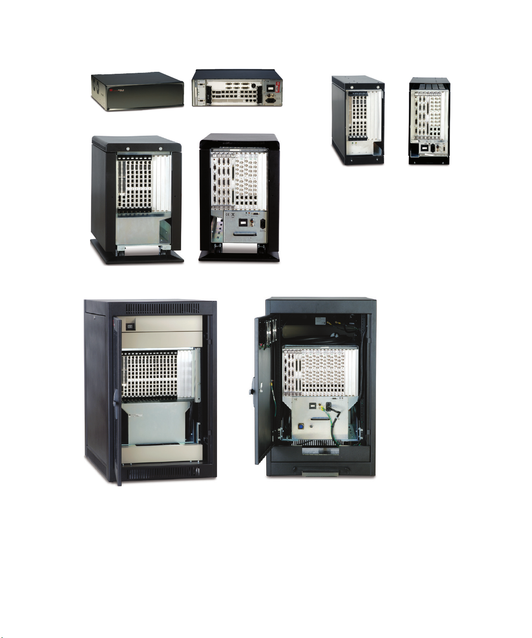
FlexTest 40 FlexTest 60
FlexTest 100
FlexTest 200
Front
(6 VME slots)
Back
(8 transition slots,
7 powered)
Back
(12 transition slots, 10 powered)
Back
(3 VME slots)
Front
(10 VME slots)
Front
(20 VME slots)
Back
(20 transition slots, 19 powered)
FlexTest Controller Overview
FlexTest Models 40/60/100/200 Controllers
MTS FlexTest® Models 40/60/100/200 Controller Hardware FlexTest Controller Configurations
29
Page 30
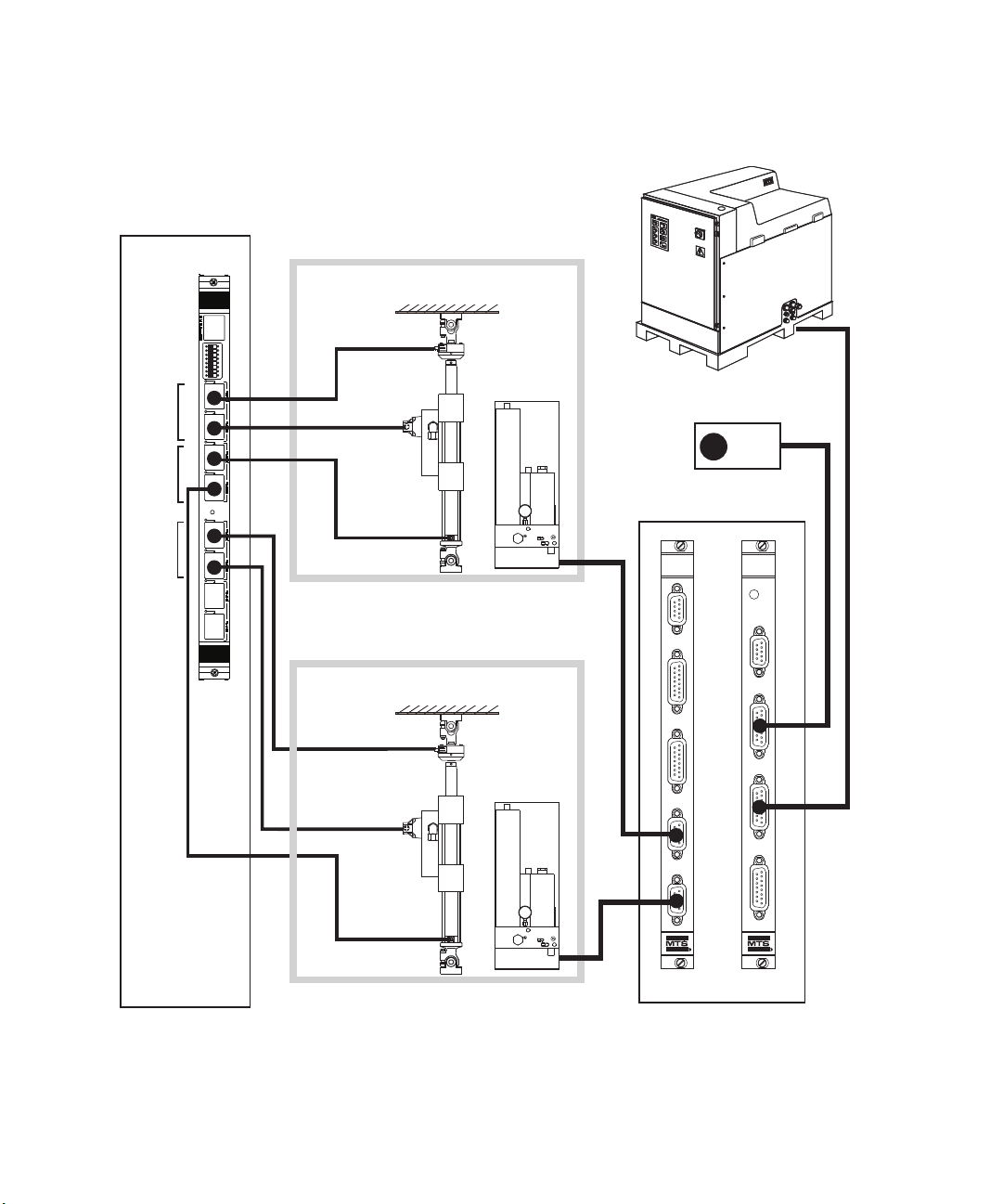
FlexTest Controller Overview
HPU
Force
Transducer
Hydraulic
Service
Manifold
(HSM)
Hydraulic
Power Unit (HPU)
Servovalve
LVDT
1
2
3
4
5
6
7
8
SERVICE
493.73
HPU
J23
E-STOP
OUT
J24
E-STOP IN
J25 HPU
J54
SYS D I/O
J49 AUX PWR
J3A STA
J3B STA
J28A HSM
J28B HSM
494.74
HSM
VME Bus
Transition Bus
494.26
Dual
DUC
494.40
I/O Carrier
Station A
E-Stop
494.16
VD/DUC
494.16
VD/DUC
Force
Transducer
Hydraulic
Service
Manifold
(HSM)
Servovalve
LVDT
Station B
Typical Series 494 Chassis Connections (FT60, FT100, FT200)
30
FlexTest Controller Configurations
MTS FlexTest® Models 40/60/100/200 Controller Hardware
Page 31

Installation
CAUTION
CAUTION
This section includes a number of installation requirements for Series 494
Controller Hardware.
Controller Installation Procedure
The following procedure provides a basic outline for the installation of FlexTest
controllers.
1. Unpack the controller.
2. Inspect the controller for any damage.
Note Report any damage to the controller to the shipping agent and MTS.
Controller electronic components can be damaged during shipping.
Installation
Using a controller with damaged components can result in injury to
personnel or equipment damage.
Do not attempt to use equipment that was damaged during shipping. Report any
damaged components to the shipping agent and MTS.
3. Move the controller chassis to the desired location.
The Model 494.10 and 494.20 Chassis weighs approximately 45 kg (100 lb)
and 60 kg (132 lb) respectively.
Improper lifting techniques can cause strained muscles and back injuries.
When lifting this chassis, take the appropriate precautions to prevent injuries to
yourself.
MTS FlexTest® Models 40/60/100/200 Controller Hardware FlexTest Controller Configurations
31
Page 32

Installation
CAUTION
WARNING
The Model 494.06 Chassis has a removable front cover that could loosen
when attempting to lift the chassis.
Lifting the Model 494.06 Chassis without first removing the front cover can
result in injury to personnel or equipment damage.
Remove the front cover on the Model 494.06 Chassis before attempting to lift the
Model 494.06 Chassis.
4. Connect power and cables as required.
If you attempt to change a cable connection while the system is in
operation, an open control loop condition can result.
An open control loop condition can cause a rapid, unexpected system
response which can result in severe personal injury, death, or damage to
equipment.
FlexTest Controller Configurations
32
Do not change any cable connections when the system is capable of motion
(electric drives are enabled, hydraulic pressure is applied, etc.). Ensure that all
cables are connected after you make any changes in the system configuration.
Also, ensure that all cables are properly connected after you make any changes in
the system configuration.
MTS FlexTest® Models 40/60/100/200 Controller Hardware
Page 33

Installation
WARNING
Unprotected cables can be damaged by hydraulic fluid, excessive
temperature, excessive strain, and contact with sharp, abrasive, or heavy
objects.
A damaged cable can cause a rapid, unexpected system response which
can result in severe personal injury, death, or damage to equipment.
Protect all system cables as described below:
• Protect electrical cables from spilled hydraulic fluid and from excessive
temperatures that can cause the cables to harden and eventually fail.
• Ensure that all cables have strain-relief devices installed at the cable and
near the connector plug. Do not use the connector plug as a strain relief.
• Protect all system cables from sharp or abrasive objects that can cause the
cable to fail.
• Use a cable cover or cable tray where cables are in traffic locations. Never
walk on cables or move heavy objects over them.
• Route cables away from areas that expose them to possible damage.
MTS FlexTest® Models 40/60/100/200 Controller Hardware FlexTest Controller Configurations
33
Page 34

Installation
Installation Requirements–Series 494 Hardware
Software settings Software is used to define the location (address) of each board used in the
system. Controller software uses this information to locate and communicate
with each board. In addition, there are other software settings that define
hardware parameters.
Blank chassis panels To help ensure proper ventilation, each blank slot in a Series 494 Chassis must
have a blank chassis panel.
Chassis grounding The controller will not function correctly if the chassis is not grounded properly.
I/O carrier settings The Model 494.40 I/O Carrier board has a number of hardware settings that must
be set before you install the board. These settings include:
• Address switch settings (required)
• The installation of bridge-completion resistors (optional)
• The installation of shunt-calibration resistors (optional)
Interlock jumper plugs Each system includes a system jumper plug kit. If interlock/E-Stop inputs are not
used, you must install a jumper plug to maintain the integrity of those interlocks.
For more information For detailed descriptions of software settings, see the controller software manuals
delivered with your system.
For detailed descriptions of I/O Carrier board settings, see “How to Set Up a
Model 494.40 I/O Carrier Board” on page 121.
FlexTest Controller Configurations
34
MTS FlexTest® Models 40/60/100/200 Controller Hardware
Page 35

Environmental Requirements—Series 494 Hardware
All Series 494 hardware components are intended for indoor use only. This
indoor environment must conform to the following environmental specifications.
Note All Series 494 Controller must only be operated under the installation
and ambient conditions (such as, temperature, moisture, and EMC)
specified.
PARAMETER SPECIFICATION
Temperature 5ºC–40ºC (41ºF–104ºF)
Humidity 5–85%, non-condensing
Altitude 3048 m (10,000 ft) maximum
Installation
Space
Requirements
Note To maintain EMC compliance, the controller must be installed in a
location that does not exceed the EN 61000-6-4 emission standard for
industrial environments.
For proper ventilation, allow 51 mm (2 in) clearance
on all sides of the chassis.
The rear of the chassis requires a minimum
clearance of 15.24 cm (6 in) for cable connections.
MTS FlexTest® Models 40/60/100/200 Controller Hardware FlexTest Controller Configurations
35
Page 36

Installation
Required
Clearance
51 mm (2 in.)
Required
Clearance
51 mm (2 in.)
102 mm
(4 in.)
100-240 VAC
50-60 Hz, 12/6A
9 8 7 6 5 4 3 2 1 B A
10
SERVICE
493.73
HPU
J23
E-STOP OUT
J24
E-STOP IN
J25 HPU
J54
SYS D I/O
J49 AUX PWR
J3A STA
J3B STA
J28A HSM
J28B HSM
494.74
HSM
J49 AUX PWR
J3A STA
J3B STA
J28A HSM
J28B HSM
494.74
HSM
First
494.75
ANALOG
INPUT
CH 1 - 8
Last
J11
J12
First
494.76
ANALOG
OUTPUT
CH 1 - 8
Last
J11
J12
Power
Over
Temp
Power
OK
J39 Power Monitor
J49 AUX PWR
J3A STA
J3B STA
J28A HSM
J28B HSM
494.74
HSM
J49 AUX PWR
J3A STA
J3B STA
J28A HSM
J28B HSM
494.74
HSM
Required
Clearance
51 mm
(2 in.)
100-240 VAC
50-60 Hz, 12/6A
9 8 7 6 5 4 3 2 1 B A
10
SERVICE
493.73
HPU
J23
E-STOP OUT
J24
E-STOP IN
J25 HPU
J54
SYS D I/O
J49 AUX PWR
J3A STA
J3B STA
J28A HSM
J28B HSM
494.74
HSM
J49 AUX PWR
J3A STA
J3B STA
J28A HSM
J28B HSM
494.74
HSM
First
494.75
ANALOG
INPUT
CH 1 - 8
Last
J11
J12
First
494.76
ANALOG
OUTPUT
CH 1 - 8
Last
J11
J12
Power
Over
Temp
Power
OK
J39 Power Monitor
J49 AUX PWR
J3A STA
J3B STA
J28A HSM
J28B HSM
494.74
HSM
J49 AUX PWR
J3A STA
J3B STA
J28A HSM
J28B HSM
494.74
HSM
CAUTION
Ventilation Requirements–Series 494 Chassis
For proper ventilation for rack-mounted chassis, you must provide 51 mm (2 in)
clearance on all sides of a Series 494 Chassis.
Note The rear of the chassis requires a minimum clearance of 15.24 cm (6 in)
for cable connections.
36
The chassis Over Temp indicator (located on the front of the Model 494.06
chassis and on the back of the Models 494.10 and 494.20 chassis) turns on
when the chassis temperature is too hot–over 50ºC (122ºF).
Failure to take immediate action to correct the overtemperature condition
can result in irreparable damage to components.
Do not operate the system when the chassis Over Temp indicator is on. Shut
down the system and check the airflow through the chassis. Check for blocked
filters and damaged fans in the chassis. If the chassis is installed in a console,
check for blocked filters and damaged fans in the console. Also, make sure that
the ambient air temperature is less than 40ºC (104ºF) and that there is at least 51
mm (2 in) clearance on all sides of the chassis.
FlexTest Controller Configurations
MTS FlexTest® Models 40/60/100/200 Controller Hardware
Page 37

Rack-Mounting Requirements–Series 494 Chassis
Shorting Bar
Signal
Common
Chassis
Ground
To install a Series 494 Chassis in most 19-inch consoles you will need a console
mounting kit.
M
OUNTING KIT PART NUMBER
494.04 Chassis Console Mounting Kit 100-152-784
494.06 Chassis Console Mounting Kit 100-174-282
494.10 Chassis Console Mounting Kit 100-183-825
Installation
494.20 Chassis Console Mounting Kit
(Vertical Console)
494.20 Chassis Console Mounting Kit
(Half-Height Console)
Grounding Requirements–Series 494 Chassis
The controller will not function correctly if the chassis is not grounded as shown.
Make sure that your power source is also properly grounded.
The chassis includes two grounds: a chassis ground and a signal common. During
manufacturing, the two grounding lugs are connected together with an external
shorting bar.
56-819-501
56-781-303
MTS FlexTest® Models 40/60/100/200 Controller Hardware FlexTest Controller Configurations
37
Page 38

Installation
WARNING
100-240 VAC
50-60 Hz, 12/6A
9 8 7 6 5 4 3 2 1 B A
10
SERVICE
493.73
HPU
J23
E-STOP OUT
J24
E-STOP IN
J25 HPU
J54
SYS D I/O
J49 AUX PWR
J3A STA
J3B STA
J28A HSM
J28B HSM
494.74
HSM
J49 AUX PWR
J3A STA
J3B STA
J28A HSM
J28B HSM
494.74
HSM
First
494.75
ANALOG
INPUT
CH 1 - 8
Last
J11
J12
First
494.76
ANALOG
OUTPUT
CH 1 - 8
Last
J11
J12
Power
Over
Temp
Power
OK
J39 Power Monitor
J49 AUX PWR
J3A STA
J3B STA
J28A HSM
J28B HSM
494.74
HSM
J49 AUX PWR
J3A STA
J3B STA
J28A HSM
J28B HSM
494.74
HSM
Series 494 Chassis (Rear)
Shorting Bar
Required
Signal common cable (part number 376999-xx) connected to other components.
Chassis ground connects to
AC power ground through the
power cord.
Improper grounding can result in unexpected actuator movement and
failure to meet EMC emission and susceptibility requirements.
Unexpected actuator movement can result in injury or death and/or damage
to the equipment.
Ensure that each controller chassis is properly grounded.
Stand-alone ground
connections
Console ground
connections
For stand-alone mounting, connect the shorting bar to both ground lugs. Tighten
the two nuts that secure the shorting bar to the ground lugs.
If you mount a Series 494 Chassis in a console, remove the shorting bar from the
chassis ground lugs and connect the chassis ground to the console rail as shown.
FlexTest Controller Configurations
38
The chassis ground connects to the AC power ground through the power cord.
The power cord must be plugged into both the chassis and the power source for
proper grounding.
MTS FlexTest® Models 40/60/100/200 Controller Hardware
Page 39

Ground Rail
Console
Power
Panel
The System Ground cable (PN
376-999-xx) connects to the test
frame and other equipment.
Use a cabinet ground
cable (PN 569-278-xx)
to connect each
controllers Chassis
Ground lug to the
vertical ground rail.
A System Ground cable (PN
376-999-xx) connects each
ground lug on the power panel
to the ground rail.
Series 494
Chassis
Series 494
Chassis
ATTENTION:
RECEPTACLE FOR CONSOLE
EQUIPMENT ONLY.
Receptacle Output:
System
Ground
System Ground
cable (PN 376-999-01)
connects the cabinet
ground stud to the
Ground Rail.
Cabinet
Ground
Stud
Cabinet
Wall
Ground
Rail
ATTENTION:
RECEPTACLE FOR CONSOLE
EQUIPMENT ONLY.
Receptacle Output:
System
Ground
Connect all Signal
Common cables here.
Connect all Chassis
Ground cables here.
Shorting Bar
Removed
Installation
MTS FlexTest® Models 40/60/100/200 Controller Hardware FlexTest Controller Configurations
39
Page 40

Installation
Outlet Strip
with circuit breaker
Outlet Strip
(printer, etc.)
Dedicated
Circuit
Locking Connector
100-240 VAC
50-60 Hz, 12/6A
9 8 7 6 5 4 3 2 1 B A
10
SERVICE
493.73
HPU
J23
E-STOP OUT
J24
E-STOP IN
J25 HPU
J54
SYS D I/O
J49 AUX PWR
J3A STA
J3B STA
J28A HSM
J28B HSM
494.74
HSM
J49 AUX PWR
J3A STA
J3B STA
J28A HSM
J28B HSM
494.74
HSM
First
494.75
ANALOG
INPUT
CH 1 - 8
Last
J11
J12
First
494.76
ANALOG
OUTPUT
CH 1 - 8
Last
J11
J12
Power
Over
Temp
Power
OK
J39 Power Monitor
J49 AUX PWR
J3A STA
J3B STA
J28A HSM
J28B HSM
494.74
HSM
J49 AUX PWR
J3A STA
J3B STA
J28A HSM
J28B HSM
494.74
HSM
Self-Standing
Enclosure
ATTENTION:
RECEPTACLE FOR CONSOLE
EQUIPMENT ONLY.
Receptacle Output:
System
Ground
100-240 VAC
50-60 Hz, 12/6A
9 8 7 6 5 4 3 2 1 B A
10
SERVICE
493.73
HPU
J23
E-STOP OUT
J24
E-STOP IN
J25 HPU
J54
SYS D I/O
J49 AUX PWR
J3A STA
J3B STA
J28A HSM
J28B HSM
494.74
HSM
J49 AUX PWR
J3A STA
J3B STA
J28A HSM
J28B HSM
494.74
HSM
First
494.75
ANALOG
INPUT
CH 1 - 8
Last
J11
J12
First
494.76
ANALOG
OUTPUT
CH 1 - 8
Last
J11
J12
Power
Over
Temp
Power
OK
J39 Power Monitor
J49 AUX PWR
J3A STA
J3B STA
J28A HSM
J28B HSM
494.74
HSM
J49 AUX PWR
J3A STA
J3B STA
J28A HSM
J28B HSM
494.74
HSM
Outlet Strip
Dedicated
Circuit
Power Panel
Internal
Power
Strip
Locking Connectors
Chassis
Power
Cords
Console Mounting
AC Power Disconnect Requirements–Series 494 Chassis
The Series 494 Chassis and the computer workstation should both be powered
from the same electrical circuit.
Note Be sure to locate the chassis so that you have adequate access to
disconnect the power cord from the chassis.
40
FlexTest Controller Configurations
MTS FlexTest® Models 40/60/100/200 Controller Hardware
Page 41

Cable Requirements–Series 494 Hardware
WARNING
WARNING
To maintain EMC compliance and help ensure optimal performance, MTS
recommends ordering all system cables from MTS. Cables should be installed so
that they are protected from conditions that could damage the cable.
Unprotected cables can be damaged by hydraulic fluid, excessive
temperature, excessive strain, and contact with sharp, abrasive, or heavy
objects.
A damaged cable can cause a rapid, unexpected system response which
can result in severe personal injury, death, or damage to equipment.
Protect all system cables as described below:
• Protect electrical cables from spilled hydraulic fluid and from excessive
temperatures that can cause the cables to harden and eventually fail.
• Ensure that all cables have strain-relief devices installed at the cable and
near the connector plug. Do not use the connector plug as a strain relief.
Installation
• Protect all system cables from sharp or abrasive objects that can cause the
cable to fail.
• Use a cable cover or cable tray where cables are in traffic locations. Never
walk on cables or move heavy objects over them.
• Route cables away from areas that expose them to possible damage.
If you attempt to change a cable connection while the system is in
operation, an open control loop condition can result.
An open control loop condition can cause a rapid, unexpected system
response which can result in severe personal injury, death, or damage to
equipment.
Do not change any cable connections when the system is capable of motion
(electric drives are enabled, hydraulic pressure is applied, etc.). Also, ensure that
all cables are properly connected after you make any changes in the system
configuration.
MTS FlexTest® Models 40/60/100/200 Controller Hardware FlexTest Controller Configurations
41
Page 42

Installation
FlexTest Controller Configurations
42
MTS FlexTest® Models 40/60/100/200 Controller Hardware
Page 43

UPS System Requirements
UPS System Requirements
UPS Systems for FlexTest 60, 100, 200, and GT Controllers
To provide an increased level of safety, such as needed to address current
European Machinery Directive, any system using an FT60, FT100, FT200, or
FTGT servo controller must have an acceptable Uninterruptable Power Supply
(UPS) properly integrated into the system.
It is important to note that the UPS will not prevent any unexpected motion if the
controller, or any other electrical subsystem required for control of the system
has an internal failure, including a HPU or a Motor Drive.
UPS requirements • The UPS must be wired to provide power to the controller and any
peripheral equipment that is instrumental in safe system operation and shutdown. In some cases it may be feasible and appropriate to provide UPS
power to the Hydraulic Power Unit (HPU).
• The UPS must be sized to provide adequate electrical power for a period of
three minutes after loss of input power.
• The controller must be configured to take appropriate actions for safe shut-
down of hydraulic equipment being controlled. (Appropriate actions depend
on the particular system.)
• Both UPS input power and UPS output power connections must include
strain relief and a twist-lock plug or equivalent.
• UPS systems used in the European Union must be CE marked.
• The UPS must have input power-loss (AC Fail) alarm relay contact out and
a low battery alarm relay contact out, both of which must be wired to the
controller's UPS monitoring interface.
Battery power
considerations
MTS FlexTest® Models 40/60/100/200 Controller Hardware FlexTest Controller Configurations
A UPS with an AC Fail relay contact wired to the controller provides a
mechanism for the controller to identify that the UPS has switched over to
battery power due to a detected AC power failure condition from the facility's
power grid. This fault signal from the UPS can be used by the controller to start a
safe shutdown sequence, ramp command(s) to a safe state(s), and then shut off
the power source.
The addition of a low battery warning relay contact out from the UPS will
provide additional system safety protection by letting the controller know that the
UPS battery is low.
43
Page 44

UPS System Requirements
UPS Systems for FlexTest 40 and FlexTest SE Servocontrollers
To provide an increased level of safety and to address current European
Machinery Directive, any system using an FT40, or FTSE servo controller must
have an acceptable Uninterruptible Power Supply (UPS) properly integrated into
the system.
It is important to note that the UPS will not prevent any unexpected motion if the
controller, or any other electrical subsystem required for control of the system
has an internal failure, including a HPU or a motor drive.
UPS requirements • The UPS must be wired to provide power to the servocontroller and any
peripheral equipment that is instrumental in safe system operation and shutdown. In some cases it may be feasible and appropriate to provide UPS
power to the hydraulic power unit (HPU).
• The UPS must be sized to provide adequate electrical power for a period of
three minutes after loss of input power.
• The controller must be configured to take appropriate actions for safe shut-
down of hydraulic equipment being controlled. (Appropriate actions depend
on the particular system.)
Battery power
considerations
• Both UPS input power and UPS output power connections must include
strain relief and a twist-lock plug or equivalent.
• UPS systems used in the European Union must be CE marked.
• FT40 (with Model 494.41 System board) and FTSE controllers do not have
dedicated UPS monitoring inputs.The UPS must have input power-loss (AC
Fail) alarm relay contact out and a low battery alarm relay contact out, both
of which must be wired to two of the digital inputs that are part of generaluse DI/O in the FT40 or FTSE controllers.
Note FT40 controllers that include a Model 494.44 or a Model 494.42 system
board have dedicated UPS inputs.
• The controller’s “Event Action” feature must be configured to take
appropriate actions for safe shut-down of hydraulic equipment being
controlled. (Appropriate actions depend on the particular system.)
A UPS with an AC Fail relay contact wired to the controller provides a
mechanism for the controller to identify that the UPS has switched over to
battery power due to a detected AC power failure condition from the facility's
power grid. This fault signal from the UPS can be used by the controller to start a
safe shutdown sequence, ramp command(s) to a safe state(s), and then shut off
the power source.
FlexTest Controller Configurations
44
MTS FlexTest® Models 40/60/100/200 Controller Hardware
Page 45

The addition of a low battery warning relay contact out from the UPS will
provide additional system safety protection by letting the controller know that the
UPS battery is low.
Specifications–UPS Systems Used with MTS Controllers
Any UPS used with an MTS system must comply with these specifications.
UPS Specifications
I
TEM REQUIREMENT
Operating temperature 5–40 deg C
Operating humidity 5–85% non-condensing
UPS System Requirements
UPS power
requirements
Supported UPS output
voltage range
Input/output frequency
range
Output load regulation -/+5% nominal operating voltage (both in
Switch-over time to battery
on power loss
100–240 V AC nominal, single phase,
sine-wave output
50–60 Hz
battery and normal operation modes)
0 s (recommended), < 6 ms (required)
The following UPS power requirements include power for the PC, MTS
Controller (one chassis), and 25% capability for other subsystems.
UPS Power Requirements
C
ONTROLLER TYPE CONTROLLER CHASSIS UPS POWER REQUIRED
FlexTest SE 493.02 1200 watt
FlexTest GT 493.10 2500 watt
Aero ST 493.20 3500 watt
Flextest 40 494.04 1200 watt
FlexTest 60 494.06 1800 watt
FlexTest 100 494.10 2500 watt
FlexTest 200 494.20 3500 watt
MTS FlexTest® Models 40/60/100/200 Controller Hardware FlexTest Controller Configurations
45
Page 46

UPS System Requirements
Controller P0 Interlock Check Utility
793-based systems include a utility that uses Telnet commands to set and clear
interlocks on various boards to identify boards that cannot set or clear interlocks.
This is often the result of a bent P0 pin on the board connector.
During normal startup, sysload will run this utility. If a problem is identified,
1. Sysload will not complete.
2. A results window lists the problem boards and the location of the log file
that contains the results.
You can also run this utility using the P0interlockcheck command line, before
sysload runs.
FlexTest Controller Configurations
46
MTS FlexTest® Models 40/60/100/200 Controller Hardware
Page 47

FlexTest 40 Controller Configuration
FlexTest 40
Digital Controller
R
About the FlexTest 40 Controller
The FlexTest 40 Controller is a fully digital proportional, integral, derivative,
feed forward (PIDF) servocontroller that provides complete control of one station
in a test system.
A FlexTest 40 Controller consists of:
• One Model 494.04 Chassis that contains controller hardware.
• A computer workstation that runs MTS controller software applications.
For a detailed listing of configuration options, see the FlexTest 40 Configuration
engineering drawing (Part number 700-003-810).
FlexTest 40 Controller Configuration
Controller capabilities
PARAMETER FLEXTEST 40
Test Stations 1
Control Channels Up to 4
Conditioned Transducer Inputs Up to 12
Auxiliary Data Inputs Up to 16
MTS FlexTest® Models 40/60/100/200 Controller Hardware FlexTest Controller Configurations
47
Page 48

FlexTest 40 Controller Configuration
Power
100-240 VAC
50-60 Hz, 1-2 A
DA Output
J24
1234567
8
1234567
8
J54 Dig In
J49 Aux Pwr
J25 Hpu
Dig Out J55
Intlk J43
E-stop J29
J28 HSM
LAN 2 LAN 1
DEBUG
MOTOROLA
10/100 BASE T 10/100 BASE T
SCSI
BUSY
PIB
BUSY
PCI MEZZANINE CARD
PCI MEZZANINE CARD
About the Model 494.04 Chassis
The Model 494.04 Chassis is a four-slot VME chassis that you can rack mount or
place on a desktop. All cabling is accessed through the rear panel.
Mezzanine cards Two slots are reserved for Model 494.40 I/O Carrier boards. Each I/O carrier
board can contain up to four mezzanine cards. You can use mezzanine cards to
condition transducers, drive servovalves, provide A-to-D inputs, and interface to
various digital transducers (such as encoders and Temposonics transducers).
Model 494.04 Chassis (rear view)
48
Hydraulic control The system board provides control of the test system hydraulics, including
hydraulic power unit (HPU) and hydraulic service manifold (HSM) control.
Interlocks The system board provides interlock inputs and outputs.
• You can use interlock-output contacts to control external devices.
• You can use interlock inputs from external devices to initiate station and
program interlocks.
System board The system board provides three optically isolated digital inputs and three relay-
contact digital outputs.
• You can use digital-input signals to trigger test events in your controller
software.
• You can use digital-output signals to control external devices.
FlexTest Controller Configurations
MTS FlexTest® Models 40/60/100/200 Controller Hardware
Page 49

Specifications–Model 494.04 Chassis
All equipment related to the controller should be connected to the same fused
power circuit.
Note Electrical connections must be made by qualified personnel and conform
to local codes and regulations. Local electrical codes supersede any
information found here.
Model 494.04 Chassis Specifications
P
ARAMETER SPECIFICATION
Input Voltage 100–240 V AC (single phase)
Input Frequency 50–60 Hz
Input Current 5 A at 100 V AC
Facility Power Requirements Provide a dedicated circuit for the
Input Surge <40 A
FlexTest 40 Controller Configuration
power factor corrected universal input
3 A at 240 V AC
chassis, computer, and monitor.
Insulation Over Voltage Category I
Pollution Degree 2
Weight Approximately 8.6 kg (19 lb)
Dimensions Width: 43 cm (17 in)
Height: 14 cm (5.5 in)
Depth: 44.5 cm (17.5 in)
MTS FlexTest® Models 40/60/100/200 Controller Hardware FlexTest Controller Configurations
49
Page 50

FlexTest 40 Controller Configuration
Power
100-240 VAC
50-60 Hz, 4-2 A
DA Output
J24
1234567
8
1234567
8
J54 Dig In
J49 Aux Pwr
J25 Hpu
Dig Out J55
Intlk J43
E-stop J29
J28 HSM
LAN 2 LAN 1
DEBUG
MOTOROLA
10/100 BASE T 10/100 BASE T
SCSI
BUSY
PIB
BUSY
PCI MEZZANINE CARD
PCI MEZZANINE CARD
Slot 4-5 - 494.41 System I/O
Slot 3 - 494.40 I/O Carrier
Slot 2 - 494.40 I/O Carrier
Slot 1 - Processor Board
Model 494.04 Chassis Boards
The Model 494.04 Chassis includes three VME bus slots that contain the boards
listed in the following table.
Rear View of the Model 494.04 Chassis
S
LOT BOARD NAME FUNCTION
Slot 1 Processor Board Provides PIDF processing and an interface between the
controller and the computer workstation.
Slots 2, 3 Model 494. 40 I/O Carrier Supports up to four mezzanine cards that can condition
transducers, drive servovalves, provide A-to-D inputs, and
interface to various digital transducers (such as encoders and
Temposonics transducers).
Slots 4, 5 System Board Provides digital I/O, E-Stop, and HSM/HPU control.
Compatible system boards include: the Model 494.41 SingleStation System Board, the Model 494.42 Single-Station
System Board, and the Model 494.44 Two-Station System
Board.
50
FlexTest Controller Configurations
MTS FlexTest® Models 40/60/100/200 Controller Hardware
Page 51

Typical Model 494.04 Chassis Connections
HPU
Power
100-240 VAC
50-60 Hz, 1-2 A
DA Output
J24
1234567
8
1234567
8
J54 Dig In
J49 Aux Pwr
J25 Hpu
Dig Out J55
Intlk J43
E-stop J29
J28 HSM
LAN 2 LAN 1
DEBUG
MOTOROLA
10/100 BASE T 10/100 BASE T
SCSI
BUSY
PIB
BUSY
PCI MEZZANINE CARD
PCI MEZZANINE CARD
Slot 3 - 494.40 I/O Carrier
Slot 2 - 494.40 I/O Carrier
Slot 1 - Processor Board
Force Transducer
Hydraulic
Service
Manifold
(HSM)
Hydraulic
Power Unit
(HPU)
Computer
Workstation
Load
Frame
E-Stop
Servovalve
J49 AUX PWR
Auxilliary DC
supply voltages
for external
devices. + 5 V
DC, +15 V DC,
-15 V DC,
+24 V DC
Slot 4-5
494.41 System I/O
J43 Interlock
Input/Output
J55
Digital
Outputs
J54
Digital
Inputs (3)
Analog
Outputs (2)
J24
Remote
E-Stop
To Digital Universal Conditioner
(DUC) Card in 494.40 I/O Carrier
LVDT
To Valve Driver
Card in 494.40
I/O Carrier
FlexTest 40 Controller Configuration
MTS FlexTest® Models 40/60/100/200 Controller Hardware FlexTest Controller Configurations
51
Page 52

J54 Dig In
J49 Aux Pwr
J25 Hpu
Dig Out J55
Intlk J43
E-stop J29
J28 HSM
Power
100-240 VAC
50-60 Hz, 1-2 A
DA Output
J24
1234567
8
1234567
8
J54 Dig In
J49 Aux Pwr
J25 Hpu
Dig Out J55
Intlk J43
E-stop J29
J28 HSM
LAN 2 LAN 1
DEBUG
MOTOROLA
10/100 BASE T10/100 BASE T
SCSI
BUSY
PIB
BUSY
PCI MEZZANINE CARD
PCI MEZZANINE CARD
J49 AUX PWR
Auxiliary DC supply
voltages for external
devices.
+ 5 V DC, +15 V DC,
-15 V DC, +24 V DC
J28 HSM
24-volt control for
HSM off/low/high or
proportional
solenoids
J43
Interlock input
Interlock output
J29
Load Frame E-Stop
J25
24 V DC HPU
control
J54
Digital inputs (3)
J55
Digital outputs (3)
494.04
Chassis
J24
Remote
E-Stop
DA
Output
(2)
Model 494.41 Single-Station System Board
Model 494.41 Single-Station System Board
About the Model 494.41 Single-Station System Board
The Model 494.41 System board is a twoslot board that is only used in the Model
494.04 Chassis. This board provides analog
and digital I/O, E-Stop, HSM, and HPU
control for one station.
Board features
External Interfaces
• Three digital inputs (J54)
• Three digital outputs (J55)
• Auxiliary power outputs for external
devices (J49)
• Two analog outputs (DA Output
connector located on the 494.04
chassis)
Hydraulic Control
• 24-volt HPU control (J25)
• 24-volt HSM control (Off/Low/High
or proportional) (J28)
• E-Stop/Interlock Control
• Load-frame E-Stop control (J29)
• Optional E-Stop control (J24-located
on the 494.04 chassis)
• One interlock input and one interlock
output (J43)
FlexTest Controller Configurations
52
MTS FlexTest® Models 40/60/100/200 Controller Hardware
Page 53

Model 494.41 System Board Specifications
Model 494.41 Specifications (part 1 of 3)
P
ARAMETER SPECIFICATION
Model 494.41 Single-Station System Board
HSM Control*
Off/Low/High
Control
Low Output
High Output
Proportional
Control
Signal Output
Solenoid
Impedance
Ramp Time
(0 to full scale)
Interlock Output
Relay
Volta ge
Current
Connector J28 (CPC-4S)
+24 V DC, 1.0 A maximum
+24 V DC, 1.0 A maximum
0–0.78 A
20–25 Ω
2.1 s or 4.2 s (software selectable)
* The type of HSM control (off/low/high or
proportional) is software configurable.
Connector J43 (D9S)
30 V DC/AC maximum
1 A maximum
Normally Open Relay Contacts: Open = Interlock
Normally Closed Relay Contacts: Closed = Interlock
Interlock Input
Interlock Trip
Volta ge
Maximum Input
Volta ge
Input Resistance
Interlock Power
Output
MTS FlexTest® Models 40/60/100/200 Controller Hardware FlexTest Controller Configurations
Connector J43 (D9S)
0.8 V minimum, 3 V maximum
+26 V DC
2700 Ω
+24 V DC (current limited by a 6.6-KΩ resistor)
53
Page 54

Model 494.41 Single-Station System Board
P
ARAMETER SPECIFICATION
Model 494.41 Specifications (part 2 of 3)
Program Interlock
Input
Input Logic
HPU Outputs
(Start/Low/High)
HPU Output
HPU ON Input
HPU Interlock
Inputs (Low Level
and Overtemp)
Trip-point Voltage
Auxiliary Power
Outputs
Connector J29 (D15S)
Switch Contact Closed = no program interlock
Switch Contact Open = program interlock
Connector J25 (D15P)
Output Voltage: 24 V DC at 10 mA
Trip Voltage: 0.9–5.5 V DC
Maximum Input Voltage: +26 V DC
Connector J25 (D15P)
18–23 V DC
Maximum Input Voltage: +26 V DC
Connector J49 (D9S)
FlexTest Controller Configurations
54
+5 V DC
+15 V DC
-15 V DC
+24 V DC
0.75 A at 40ºC (104ºF)
0.75 A at 40ºC (104ºF)
0.75 A at 40ºC (104ºF)
0.75 A at 40ºC (104ºF)
MTS FlexTest® Models 40/60/100/200 Controller Hardware
Page 55

Model 494.41 Specifications (part 3 of 3)
P
ARAMETER SPECIFICATION
Model 494.41 Single-Station System Board
Digital Output
Relays
Volta ge
Current
Output logic
Aux. Voltage
Digital Inputs
Input ON/OFF Trip
Volta ge
Maximum Input
Volta ge
Input Resistance
Connector J55 (D9S)
30 V AC/DC maximum
1 A maximum
Output 1: One normally open (NO) contact
Open = Output is OFF
Output 2: One normally open (NO) contact and one
normally closed (NC) contact
NO Contact: Open = Output is OFF
NC Contact: Closed = Output is OFF
Output 3: One normally open (NO) contact
Open = Output is OFF
24 V DC, 0.75 A at 40ºC
Connector J54 (D9P)
0.8–3 V DC
+ 26 V DC
2.7 KΩ
Digital Input Power
Output
D/A Outputs
Resolution
Output Type
Output Voltage
Output Current
MTS FlexTest® Models 40/60/100/200 Controller Hardware FlexTest Controller Configurations
+ 24 V DC (current limited by 6.6-KΩ resistor)
Connector "D/A Output" (D9P)
16 bit
Single ended
+/- 10 V full scale
5.0 mA maximum
Note This connector is located on the rear panel
of the 494.04 chassis.
55
Page 56

Model 494.41 Single-Station System Board
Power
100-240 VAC
50-60 Hz, 1-2 A
DA Output
J24
1234567
8
1234567
8
J54 Dig In
J49 Aux Pwr
J25 Hpu
Dig Out J55
Intlk J43
E-stop J29
J28 HSM
LAN 2 LAN 1
DEBUG
MOTOROLA
10/100 BASE T10/100 BASE T
SCSI
BUSY
PIB
BUSY
PCI MEZZANINE CARD
PCI MEZZANINE CARD
494.04 Chassis
494.41 System
Board
J24 E-Stop
J24
8
13
5
7
E-Stop Box
J24 Emergency Stop Connections for the Model 494.41 System Board
The Model 494.41 System board provides two E-Stop inputs that are available on
the J24 E Stop connector (located on the rear panel of the Model 494.04
Chassis).
Cable specification To maintain EMC compliance, the J24 E-Stop cable must comply with the
following specifications:
Connector type–15-pin, type D, male EMI connector.
Backshell–EMI metallized plastic or metal.
Cable–24 AWG, four-conductor with braided shield, with the braid connected to
a metallized plastic backshell at the chassis and to ground at the emergency stop
(E-Stop) box.
Jumper plug required If connector J24 is not used, you must install a jumper plug to maintain the
integrity of the interlocks. Use jumper plug part number 039-713-201 or jumper
pins 5-7 and 8-13.
FlexTest Controller Configurations
56
MTS FlexTest® Models 40/60/100/200 Controller Hardware
Page 57

Model 494.41 Single-Station System Board
Power
100-240 VAC
50-60 Hz, 1-2 A
DA Output
J24
1234567
8
1234567
8
J54 Dig In
J49 Aux Pwr
J25 Hpu
Dig Out J55
Intlk J43
E-stop J29
J28 HSM
LAN 2 LAN 1
DEBUG
MOTOROLA
10/100 BASE T10/100 BASE T
SCSI
BUSY
PIB
BUSY
PCI MEZZANINE CARD
PCI MEZZANINE CARD
ON = Normal
ON = Normal
ON = HPU ON
Controller 24 V DC
HPU
ON
Sense
24 V DC (from HPU)
Start
Lo
High
HPU Over Temp
Open = Interlock Active
494.41 System Board
9
10
11
12
1
2
3
4
5
6
7
8
J25
HPU
HPU Low Level
Open = Interlock Active
Start
SSR
Low
SSR
High
SSR
24 V DC (from HPU)
HPU ON
Series 505 HPU or Equivalent
J25
HPU
+24 V DC (from HPU)
HPU E-Stop Out 1
Open = HPU E Stop
J25 Hydraulic Power Unit Connections for the Model 494.41 System Board
Connector J25 HPU provides 24-volt logic signals that control the hydraulic
power unit (HPU). The connector can be connected directly to MTS Series 505
HPUs and similar HPUs with low-current, 24-volt input controls.
Note Other MTS HPUs require the Model 493.07 HPU Converter Box to
convert the low-current HPU output signal to a signal that can drive the
HPU relay.
MTS FlexTest® Models 40/60/100/200 Controller Hardware FlexTest Controller Configurations
57
Page 58

Model 494.41 Single-Station System Board
CAU TION
Control voltages for hydraulic power units vary between models. The
interface between the Model 494.41 System board and an HPU consists of
24-volt logic signals.
Connecting J25 to a non-compliant HPU can damage the board.
Do not connect 24 V DC relay circuitry or 115 V AC circuitry to connector J25 on
the Model 494.41 System board.
Cable specification To maintain EMC compliance, J25 HPU cables must comply with the following
specifications:
Connector—15-contact, type-D, female EMI connector.
Backshell–EMI metallized plastic or metal.
Cable—22 AWG, 10-conductor with braided shield with the shield connected to
metallized plastic or metal backshell to the chassis.
Jumper plug required If connector J25 HPU is not used, you must install a jumper plug to maintain the
integrity of the interlocks. Use jumper plug part number 039-713-301 or jumper
pins 1–7, 2–3–5, 6–9, 8–10–11–12.
FlexTest Controller Configurations
58
MTS FlexTest® Models 40/60/100/200 Controller Hardware
Page 59

Model 494.41 Single-Station System Board
494.41 System I/O Board
J28 HSM
1
4
2
3
+24V
HSM Low
Solenoid
HSM High
Solenoid
High
Low
494.41 System I/O Board
J28 HSM
4
2
3
HSM Proportional
Control
Current
Amplifier
Power
100-240 VAC
50-60 Hz, 1-2 A
DA Output
J24
1234567
8
1234567
8
J54 Dig In
J49 Aux Pwr
J25 Hpu
Dig Out J55
Intlk J43
E-stop J29
J28 HSM
LAN 2 LAN 1
DEBUG
MOTOROLA
10/100 BASE T10/100 BASE T
SCSI
BUSY
PIB
BUSY
PCI MEZZANINE CARD
PCI MEZZANINE CARD
(Off/Low/High HSM Control)
(Proportional HSM Control)
J28 HSM
J28 HSM Connections for the Model 494.41 System Board
HSM control (off/low/high or proportional) is software configurable. The Model
494.41 Board provides separate 24-volt, low-pressure and high-pressure outputs
that drive the HSM low- and high-pressure solenoids. Proportional control
provides a current output from 0 to 0.78 A.
Note The Model 494.41 Board cannot be used with 115 V AC HSMs.
Applications that use 115 V AC HSMs require an external converter box
(such as a Model 413.08), which is used with this board.
Cable specification To maintain EMC compliance, J25 HPU cables must comply with the following
specifications:
Connector—4-contact, CPC-4P, male EMI connector.
Proportional Control Cable—18 AWG, 2-conductor with foil shield with the
drain wire connected to pin 3 of the CPC connector.
Off/low/high Control Cable—18 AWG, 3-conductor with foil shield with the
drain wire connected to pin 3 of the CPC connector.
MTS FlexTest® Models 40/60/100/200 Controller Hardware FlexTest Controller Configurations
59
Page 60

Model 494.41 Single-Station System Board
Controller Interlock
Open = Controller Interlock
494.41 System Board
Power
100-240 VAC
50-60 Hz, 1-2 A
DA Output
J24
1234567
8
1234567
8
J54 Dig In
J49 Aux Pwr
J25 Hpu
Dig Out J55
Intlk J43
E-stop J29
J28 HSM
LAN 2 LAN 1
DEBUG
MOTOROLA
10/100 BASE T10/100 BASE T
SCSI
BUSY
PIB
BUSY
PCI MEZZANINE CARD
PCI MEZZANINE CARD
Fused 24 V DC
to Crosshead
J29
E Stop
1
4
3
2
7
5
8
13
12
14
Crosshead Interlock
Common
+24V
External Program
Interlock Source
Open=Program Interlock
HPU E Stop
+24V
HSM High
Crosshead Unlock Power
Crosshead Unlock
Power Common
J29 E-Stop
To HPU E Stop Chain
* MTS Model 505 Pumps and older do not use the
HPU E-Stop 2 signal.
J29 Emergency Stop Connections for the Model 494.41 System Board
Connector J29 E-STOP provides an output to external devices when an
emergency stop signal is generated. You can also connect an external E-Stop to
the J29 connector.
Cable specification To maintain EMC compliance, the J29 E-STOP cable must comply with the
following specifications:
Connector type–15-pin, type D, male EMI connector.
Backshell–EMI metallized plastic or metal.
Cable–18 AWG, 8-conductor with foil shield, with the drain wire connected to a
metallized plastic backshell at the chassis.
Jumper plug required If connector J29 is not used, you must install a jumper plug to maintain the
integrity of the interlocks. Use jumper plug part number 100-007-947 or jumper
60
FlexTest Controller Configurations
pins 3-4, 5-7, 8-13, and 11-15.
MTS FlexTest® Models 40/60/100/200 Controller Hardware
Page 61

Model 494.41 Single-Station System Board
+24V
1
2
3
4
Interlock Disabled
+24V
1
2
3
4
Switch Contact
(Open = Interlock)
+24V
1
2
3
4
Logic Input
(0=Interlock)
Interlock In (Gnd)
Interlock Out (NO)
Interlock = Open
Interlock Out (NC)
Interlock = Closed
Common
- Interlock In
+ Interlock In
Interlock In (Pwr)
+24V
J43
Intlk
494.41 System Board
6
7
8
1
2
3
4
Interlock
Output
Interlock
Input
Power
100-240 VAC
50-60 Hz, 1-2 A
DA Output
J24
1234567
8
1234567
8
J54 Dig In
J49 Aux Pwr
J25 Hpu
Dig Out J55
Intlk J43
E-stop J29
J28 HSM
LAN 2 LAN 1
DEBUG
MOTOROLA
10/100 BASE T10/100 BASE T
SCSI
BUSY
PIB
BUSY
PCI MEZZANINE CARD
PCI MEZZANINE CARD
J43 Interlock
J43 Interlock Connections for the Model 494.41 System Board
Connector J43 Interlock provides one optically isolated interlock input and a
relay-contact interlock output.
MTS FlexTest® Models 40/60/100/200 Controller Hardware FlexTest Controller Configurations
Cable specification To maintain EMC compliance, the J43 Interlock cable must comply with the
following specifications:
Connector type–9-pin, type D, male EMI connector.
Backshell–EMI metallized plastic or metal.
Cable–shielded twisted pairs (24 AWG minimum), braided shield with the shield
connected to the metallized backshell at the chassis.
Jumper plug required If connector J43 is not used, you must install a jumper plug to maintain the
integrity of the interlocks. Use jumper plug part number 100-057-245, or jumper
pins 1-2, 3-4, and 5-9.
61
Page 62

Model 494.41 Single-Station System Board
494.41 System Board
Power
100-240 VAC
50-60 Hz, 1-2 A
DA Output
J24
1234567
8
1234567
8
J54 Dig In
J49 Aux Pwr
J25 Hpu
Dig Out J55
Intlk J43
E-stop J29
J28 HSM
LAN 2 LAN 1
DEBUG
MOTOROLA
10/100 BASE T10/100 BASE T
SCSI
BUSY
PIB
BUSY
PCI MEZZANINE CARD
PCI MEZZANINE CARD
+24 V
-15V
+ 15 V
+24 V
Gnd (+24 V)
+5V
J49 Aux Pwr
1
6
2
7
3
4
5
8
9
Gnd (+/- 15 V)
Gnd (+/- 15 V)
- 15 V
+15V
Gnd (+5 V)
+ 5 V
+ 15 V
J49 Auxiliary Power
J49 Auxiliary Power Connections for the Model 494.41 System Board
The J49 Aux Pwr connector provides fused (self resetting) auxiliary power
outputs for: +5 V DC, +15 V DC, -15 V DC, and +24 V DC.
Cable specification To maintain EMC compliance, the J49 Auxiliary Power cable must comply with
the following specifications:
Connector type–9-pin, type D, male EMI connector.
Backshell–EMI metallized plastic or metal.
MTS FlexTest® Models 40/60/100/200 Controller Hardware
FlexTest Controller Configurations
62
Cable–AWG and number of conductors as required. Braided shield with the
shield connected to the metallized backshell at the chassis.
Page 63

Model 494.41 Single-Station System Board
494.41 System Board
Power
100-240 VAC
50-60 Hz, 1-2 A
DA Output
J24
1234567
8
1234567
8
J54 Dig In
J49 Aux Pwr
J25 Hpu
Dig Out J55
Intlk J43
E-stop J29
J28 HSM
LAN 2 LAN 1
DEBUG
MOTOROLA
10/100 BASE T10/100 BASE T
SCSI
BUSY
PIB
BUSY
PCI MEZZANINE CARD
PCI MEZZANINE CARD
J54 Digital Input
Logic Input Wiring
1
2
3
4
5
6
7
8
9
J54
Dig In
Input 1
+24 V
Low side of Opto
Inputs must be
jumpered to
ground. Use 22
AWG Jumper Wire.
Switch
or dry
contacts
Input 3
Input 2
+24 V DC
Opto-
Coupler
1
2
3
J54
External
Device
J54 Digital Input Connections for the Model 494.41 System Board
Connector J54 Dig In accepts up to three optically isolated digital-input signals
from external devices. You can use these digital input signals to trigger test
events in controller applications.
Cable specification To maintain EMC compliance, the J54 Digital Input cable must comply with the
following specifications:
Connector type–9-pin, type D, male EMI connector.
MTS FlexTest® Models 40/60/100/200 Controller Hardware FlexTest Controller Configurations
Cable–AWG and number of conductors as required. Braided shield with the
shield connected to the metallized backshell at the chassis.
Back shell–EMI metallized plastic or metal.
63
Page 64

Model 494.41 Single-Station System Board
Relay Contact
Relay Contact
Relay Contact
494.41 System Board
Power
100-240 VAC
50-60 Hz, 1-2 A
DA Output
J24
1234567
8
1234567
8
J54 Dig In
J49 Aux Pwr
J25 Hpu
Dig Out J55
Intlk J43
E-stop J29
J28 HSM
LAN 2 LAN 1
DEBUG
MOTOROLA
10/100 BASE T10/100 BASE T
SCSI
BUSY
PIB
BUSY
PCI MEZZANINE CARD
PCI MEZZANINE CARD
J55
1
2
3
4
5
6
7
8
9
Output 1
Output 3
+24 V
Output 2
Aux Power
J55 Digital Output
J55 Digital Output Connections for the Model 494.41 System Board
Connector J55 Dig Out provides three general-purpose digital outputs that can
send digital-logic signals to external switches or logic devices.
Cable specification To maintain EMC compliance, the J55 Digital Output cable must comply with
the following specifications:
Connector–9-pin, type D, male EMI connector.
MTS FlexTest® Models 40/60/100/200 Controller Hardware
FlexTest Controller Configurations
64
Back shell–EMI metallized plastic.
Cable–AWG and number of conductors as required. Braided shield with the
shield connected to the metallized backshell at the chassis.
Page 65

Model 494.41 Single-Station System Board
Power
100-240 VAC
50-60 Hz, 1-2 A
DA Output
J24
1234567
8
1234567
8
J54 Dig In
J49 Aux Pwr
J25 Hpu
Dig Out J55
Intlk J43
E-stop J29
J28 HSM
LAN 2 LAN 1
DEBUG
MOTOROLA
10/100 BASE T10/100 BASE T
SCSI
BUSY
PIB
BUSY
PCI MEZZANINE CARD
PCI MEZZANINE CARD
494.04 Chassis
494.41 System
Board
D/A Output
D/A Output
2
6
4
9
Monitor 1
Monitor 2
-
+
D/A Output 1
D/A Output 2
-
+
Twisted
Pairs
Analog Output Connections for the Model 494.41 System Board
The Model 494.41 System board provides two analog output signals that are
available on the D/A Output connector (located on the rear panel of the Model
494.04 Chassis). Each D/A output is software defined.
Cable specification To maintain EMC compliance, the D/A Output cable must comply with the
following specifications:
Connector type–9-pin, type D, male EMI connector.
Backshell–EMI metallized plastic or metal.
Cable–shielded twisted pairs (24 AWG minimum), braided shield with the shield
connected to the metallized backshell at the chassis.
MTS FlexTest® Models 40/60/100/200 Controller Hardware FlexTest Controller Configurations
65
Page 66

Model 494.41 Single-Station System Board
494.41 System I/O Board
Power
100-240 VAC
50-60 Hz, 1-2 A
DA Output
J24
1234567
8
1234567
8
J54 Dig In
J49 Aux Pwr
J25 Hpu
Dig Out J55
Intlk J43
E-stop J29
J28 HSM
LAN 2 LAN 1
DEBUG
MOTOROLA
10/100 BASE T10/100 BASE T
SCSI
BUSY
PIB
BUSY
PCI MEZZANINE CARD
PCI MEZZANINE CARD
J54 Digital Input
+24 V DC
UPS
AC Fail Contacts
Open = Logic 0
1
2
3
8
4
5
J54
Dig In
Digital Input 1
Low Battery Contacts
Open = Logic 0
Digital Input 2
UPS Connections for the Model 494.41 System Board (FT40)
The following drawing shows UPS connections for the Model 494.41 System
board. Once connected, use your controller software to add the digital input
resources and configure the digital inputs to perform various actions in response
to the UPS signals.
Note See your controller software user guide for information on how digital
inputs are assigned and used.
Cable specification To maintain EMC compliance, the J54 Digital Input cable must comply with the
following specifications:
FlexTest Controller Configurations
66
Connector type–9-pin contact, type D, male EMI connector.
Back shell–EMI metallized plastic or metal.
Cable—26 to 22 AWG, 4-conductor with an overall braided shield that is
connected to the backshell at the chassis.
MTS FlexTest® Models 40/60/100/200 Controller Hardware
Page 67

Power
100-240 VAC
50-60 Hz, 1-2 A
DA Output
J24
1234567
8
1234567
8
LAN 2 LAN 1
DEBUG
MOTOROLA
10/100 BASE T10/100 BASE T
SCSI
BUSY
PIB
BUSY
PCI MEZZANINE CARD
PCI MEZZANINE CARD
J54 Dig InJ55 Dig Out
J43 INTLKJ56 UPS
J49 Aux Pwr J23 Estop/Run
J29 Load FrameJ25 HPU
J28 HSM
J54 Dig In J55 Dig Out
J43 INTLK J56 UPS
J49 Aux Pwr J23 Estop/Run
J29 Load Frame J25 HPU
J28 HSM
J49 AUX PWR
Auxiliary DC supply
voltages for external
devices:
+ 5 V DC, +15 V DC,
-15 V DC, +24 V DC
J28 HSM
24-volt control for
HSM off/low/high or
proportional solenoid
plus an HSM Estop
input
J43 Intlk
Interlock input
Interlock output
Event input
J29 Load Frame
Load Frame E-Stop
J25 HPU
24 V DC HPU control
for one HPU channel
J54 Dig In
Digital inputs (3)
J55 Dig Out
Digital outputs (3)
Model
494.04
Chassis
J23 Estop/Run
2 Estop NO outputs
1 set of Run NO/NC
outputs
DA Output (2))
J24 E-Stop
(Optional)
J56 UPS
UPS digital inputs
ACFail, Low battery
Model 494.42 Single-Station System Board
Model 494.42 Single-Station System Board
About the Model 494.42 Single-Station System Board
The Model 494.42 System Board is a twoslot board that is only used in the Model
494.04 Chassis. This board provides analog
and digital I/O, E-Stop, HSM, UPS, and
HPU control for one station.
Board features
External Interfaces
• Three digital inputs (J54)
• Three digital outputs (J55)
• Auxiliary power outputs for external
devices (J49)
• UPS inputs (J56) ACFail and low
battery inputs (switch contacts)
Hydraulic Control
• Two analog outputs (DA Output
• 24-volt HPU control (J25)
• 24-volt HSM control (Off/Low/High or
E-Stop/Interlock Control
• Load-frame E-Stop and crosshead
• Optional E-Stop inputs (J24-located on
• Interlock (J43) provides one interlock
• E-Stop/Run outputs (J23)
MTS FlexTest® Models 40/60/100/200 Controller Hardware FlexTest Controller Configurations
connector on the 494.04 chassis)
proportional) for one HSM (J28)
control for one load frame (J29)
the 494.04 chassis)
input, one interlock output, and a
software-defined event input
67
Page 68

Model 494.42 Single-Station System Board
Model 494.42 System Board Specifications
Model 494.42 Specifications (part 1 of 4)
P
ARAMETER SPECIFICATION
E-Stop/Run
Output Relay
Contacts
Vol tage
Current
HPU Outputs
(Start/Low/High)
HPU Outputs
(start, low, high)
HPU ON Input
HPU Interlock
Inputs (Low Level
and Overtemp)
Connector J23 (D9S)
30 V DC/AC maximum
1 A maximum
Two (2) Normally Open Estop Relay Contacts:
HPU E-Stop = Open
Set of NO/NC Prog. Run Relay Contacts:
Normally Open Contacts: Prog. Run = Closed
Normally Closed Contacts: Prog. Run = Open
Connector J25 (D15P)
Output Voltage: 24 V DC at 250 mA
Trip Voltage: 0.8–10.0 V DC
Maximum Input Voltage: +26 V DC
Connector J25 (D15P)
FlexTest Controller Configurations
68
Trip-point Voltage
0.8–10.0 V DC
Maximum Input Voltage: +26 V DC
MTS FlexTest® Models 40/60/100/200 Controller Hardware
Page 69

Model 494.42 Specifications (part 2 of 4)
P
ARAMETER SPECIFICATION
Model 494.42 Single-Station System Board
HSM Control*
Off/Low/High
Control
Low Output
High Output
Proportional
Control
Signal Output
Solenoid
Impedance
Ramp Time
(0 to full scale)
Load Frame
E-Stop
Crosshead Unlock
Output
Program Interlock
Input
Connector J28 (D-9S)
+24 V DC, 1.0 A maximum
+24 V DC, 1.0 A maximum
0–0.78 A
20–25 Ω
2.1 s or 4.2 s (software selectable)
* The type of HSM control (off/low/high or
proportional) is software configurable.
Connector J29 (D15S)
24 V DC at 1 A
Switch Contact Closed = no program interlock
Switch Contact Open = program interlock
Interlock Output
Relay
Vol tage
Current
MTS FlexTest® Models 40/60/100/200 Controller Hardware FlexTest Controller Configurations
Connector J43 (D9S)
30 V DC/AC maximum
1 A maximum
Normally Open Relay Contacts: Open = Interlock
Normally Closed Relay Contacts: Closed = Interlock
69
Page 70

Model 494.42 Single-Station System Board
P
ARAMETER SPECIFICATION
Model 494.42 Specifications (part 3 of 4)
Interlock Input
Interlock Trip
Vol tage
Maximum Input
Vol tage
Input Resistance
Interlock Power
Output
Event SwitchContact Input
Auxiliary Power
Outputs
+5 V DC
+15 V DC
-15 V DC
+24 V DC
Connector J43 (D9S)
0.8 V minimum, 3 V maximum
+26 V DC
2700 Ω
+24 V DC (current limited by a 15-KΩ resistor)
Connector J43 (D9S)
Event contacts open= Active event
Event contacts closed= Inactive event
Connector J49 (D9S)
0.75 A maximum
0.75 A maximum
0.75 A maximum
0.75 A maximum
FlexTest Controller Configurations
70
Digital Inputs
Input ON/OFF Trip
Vol tage
Maximum Input
Vol tage
Input Resistance
Digital Input Power
Output
Connector J54 (D9P)
0.8–3 V DC
+ 26 V DC
2.7 KΩ
+ 24 V DC (current limited by 2.7-KΩ resistor)
MTS FlexTest® Models 40/60/100/200 Controller Hardware
Page 71

Model 494.42 Specifications (part 4 of 4)
P
ARAMETER SPECIFICATION
Model 494.42 Single-Station System Board
Digital Output
Relays
Vol tage
Current
Output logic
Aux. Voltage
UPS Alarm Inputs Connector J56 (D9S)
Connector J55 (D9S)
30 V AC/DC maximum
1 A maximum
Output 1: One normally open (NO) contact
Open = Output is OFF
Output 2: One normally open (NO) contact and one
normally closed (NC) contact
NO Contact: Open = Output is OFF
NC Contact: Closed = Output is OFF
Output 3: One normally open (NO) contact
Open = Output is OFF
24 V DC, 0.75 A
UPS ACFAIL Alarm Input (switch contact):
Open=UPS ACFAIL active (logic 1)
Closed= UPS ACFAIL not active (logic 0)
UPS Low Battery Alarm Input (switch contact):
Open=UPS Low Battery active (logic 1)
Closed= UPS Low Battery not active (logic 0)
D/A Outputs
Resolution
Output Type
Output Voltage
Output Current
MTS FlexTest® Models 40/60/100/200 Controller Hardware FlexTest Controller Configurations
Connector "D/A Output" (D9P)
16 bit
Single ended
+/- 10 V full scale
5.0 mA maximum
Note This connector is located on the rear panel
of the Model 494.04 Chassis.
71
Page 72

Model 494.42 Single-Station System Board
E-Stop 1 Output (NO)
HPU E-Stop = Open
494.42 System Board
J23 Estop/Run
E-Stop 2 Output (NO)
HPU E-Stop = Open
Program Run 1 Output (NC)
Program Run = Open
Program Run 2 Output (NO)
Program Run = Closed
Reserved
J23
Estop/Run
1
2
3
4
5
7
6
8
9
Power
100-240 VAC
50-60 Hz, 1-2 A
DA Output
J24
1234567
8
1234567
8
LAN 2 LAN 1
DEBUG
MOTOROLA
10/100 BASE T10/100 BASE T
SCSI
BUSY
PIB
BUSY
PCI MEZZANINE CARD
PCI MEZZANINE CARD
J54 Dig InJ55 Dig Out
J43 INTLKJ56 UPS
J49 Aux Pwr J23 Estop/Run
J29 Load FrameJ25 HPU
J28 HSM
Reserved
J23 E-Stop/Run Output Connections for the Model 494.42 System Board
The Model 494.42 System Board provides E-Stop/Program Run outputs that are
available on the J23 E-Stop/Run connector.
Cable specification To maintain EMC compliance, the J23 E-Stop/Run cable must comply with the
FlexTest Controller Configurations
72
following specifications:
Connector type–9-pin, type D, male EMI connector.
Backshell–EMI metallized plastic or metal.
Cable–4-conductor with braided shield, with the braid connected to a metallized
plastic backshell at the chassis.
MTS FlexTest® Models 40/60/100/200 Controller Hardware
Page 73

Model 494.42 Single-Station System Board
494.04 Chassis
494.42 System
Board
J24 E-Stop
Power
100-240 VAC
50-60 Hz, 1-2 A
DA Output
J24
1234567
8
1234567
8
LAN 2 LAN 1
DEBUG
MOTOROLA
10/100 BASE T10/100 BASE T
SCSI
BUSY
PIB
BUSY
PCI MEZZANINE CARD
PCI MEZZANINE CARD
J54 Dig InJ55 Dig Out
J43 INTLKJ56 UPS
J49 Aux Pwr J23 Estop/Run
J29 Load FrameJ25 HPU
J28 HSM
J24
8
13
5
7
E-Stop Box
J24 Emergency Stop Connections for the Model 494.42 System Board
The Model 494.42 System Board provides two optional E-Stop inputs that are
available on the J24 E Stop connector (located on the rear panel of the Model
494.04 Chassis).
Jumper plug required If connector J24 is not used, you must install a jumper plug to maintain the
MTS FlexTest® Models 40/60/100/200 Controller Hardware FlexTest Controller Configurations
Cable specification To maintain EMC compliance, the J24 E-Stop cable must comply with the
following specifications:
Connector type–15-pin, type D, male EMI connector.
Backshell–EMI metallized plastic or metal.
Cable–24 AWG 4-conductor with braided shield, with the braid connected to a
metallized plastic backshell at the chassis and to ground at the emergency stop
(E-Stop) box.
integrity of the interlocks. Use jumper plug part number 039-713-201 or jumper
pins 5-7 and 8-13.
73
Page 74

Model 494.42 Single-Station System Board
ON = Normal
ON = Normal
ON = HPU ON
Power
100-240 VAC
50-60 Hz, 1-2 A
DA Output
J24
1234567
8
1234567
8
LAN 2 LAN 1
DEBUG
MOTOROLA
10/100 BASE T10/100 BASE T
SCSI
BUSY
PIB
BUSY
PCI MEZZANINE CARD
PCI MEZZANINE CARD
J54 Dig InJ55 Dig Out
J43 INTLKJ56 UPS
J49 Aux Pwr J23 Estop/Run
J29 Load FrameJ25 HPU
J28 HSM
Controller 24 Vdc
+24 V DC (from HPU)
HPU
ON
Sense
24 V DC (from HPU)
Start
Lo
High
HPU Over Temp
Open = Interlock Active
494.42 System Board
9
10
11
12
1
2
3
4
5
6
15
7
8
J25
HPU
HPU Low Level
Open = Interlock Active
Start
SSR
Low
SSR
High
SSR
24 V DC (from HPU)
HPU ON
Series 505 HPU or Equivalent
J25
HPU
HPU E-Stop Out 1
* MTS Model 505 Pumps and older do not use the
HPU E-Stop 2 signal.
HPU E-Stop Out 2*
Open = HPU E Stop
J25 Hydraulic Power Unit Connections for the Model 494.42 System I/O Board
Connector J25 HPU provides 24-volt logic signals that control the hydraulic
power unit (HPU). The connector may be connected directly to MTS Series 505
HPUs and similar HPUs that use low-current, 24-volt input controls.
Note Other MTS HPUs require the Model 493.07 HPU Converter Box to
convert the low-current HPU output signal to a signal that can drive the
HPU relay.
FlexTest Controller Configurations
74
MTS FlexTest® Models 40/60/100/200 Controller Hardware
Page 75

Model 494.42 Single-Station System Board
CAU TION
Control voltages for hydraulic power units vary between models
The HPU interface between the Model 494.42 System I/O board and an HPU
is 24-volt logic signals. Connecting J25 to a non-compliant HPU can damage
the board.
Do not connect 24 V DC relay circuitry or 115 V AC circuitry to connector J25 on
the Model 494.42 System I/O board.
Cable specification To maintain EMC compliance, J25 HPU cables must comply with the following
specifications:
Connector—15-contact, type-D, female EMI connector.
Backshell–EMI metallized plastic or metal.
Cable—22 AWG, 10-conductor with braided shield with the shield connected to
metallized plastic or metal backshell to the chassis.
Jumper plug required If connector J25 HPU is not used, you must install a jumper plug to maintain the
integrity of the interlocks. Use jumper plug PN 039-713-301 or jumper pins 1–7,
2–3–5, 6–9, 8–10–11–12.
MTS FlexTest® Models 40/60/100/200 Controller Hardware FlexTest Controller Configurations
75
Page 76

Model 494.42 Single-Station System Board
Current
Amplifier
494.42 System Board
+24V
HSM Low
Solenoid
HSM High
Solenoid
High
Low
J28 (D9S)
7
4
8
6
1
5
9
HSM Proportional
Control
J28 HSM
Power
100-240 VAC
50-60 Hz, 1-2 A
DA Output
J24
1234567
8
1234567
8
LAN 2 LAN 1
DEBUG
MOTOROLA
10/100 BASE T10/100 BASE T
SCSI
BUSY
PIB
BUSY
PCI MEZZANINE CARD
PCI MEZZANINE CARD
J54 Dig InJ55 Dig Out
J43 INTLKJ56 UPS
J49 Aux Pwr J23 Estop/Run
J29 Load FrameJ25 HPU
J28 HSM
Reserved
Reserved
2,3
J28 HSM Connections for the Model 494.42 System Board
HSM control (off/low/high or proportional) is software configurable. The Model
494.42 board provides separate 24-volt, low-pressure and high-pressure outputs
that drive the HSM low- and high-pressure solenoids. Proportional solenoid
control provides a current output from 0 to 0.78 A.
Note The Model 494.42 board can not be used with 115 V AC HSMs.
Applications that use 115 V AC HSMs require an external converter box
(such as a Model 413.08), which is used with this board.
Cable specification To maintain EMC compliance, J28 HSM cables must comply with the following
FlexTest Controller Configurations
76
specifications:
Connector—9-pin type D male EMI connector.
Backshell—EMI metallized plastic or metal.
Proportional Control Cable—18 AWG, 2-conductor with foil shield drain wire
connected to conductive backshell.
Off/low/high Control Cable—18 AWG, 3-conductor with foil shield drain wire
connected to conductive backshell.
MTS FlexTest® Models 40/60/100/200 Controller Hardware
Page 77

Model 494.42 Single-Station System Board
HPU E Stop 2*
To HPU E Stop Chain
Controller Interlock
Open = Controller Interlock
494.42 System Board
Fused 24 V DC
to Crosshead
J29
1
4
3
2
7
5
8
13
11
15
12
14
Crosshead Interlock
Common
+24V
External Program
Interlock Source
Open=Program Interlock
To HPU E Stop Chain
HPU E Stop 1
+24V
HSM High
Crosshead Unlock Power
Crosshead Unlock
Power Common
Load Frame
J29
Pins 6,9,10 Reserved
Power
100-240 VAC
50-60 Hz, 1-2 A
DA Output
J24
1234567
8
1234567
8
LAN 2 LAN 1
DEBUG
MOTOROLA
10/100 BASE T10/100 BASE T
SCSI
BUSY
PIB
BUSY
PCI MEZZANINE CARD
PCI MEZZANINE CARD
J54 Dig InJ55 Dig Out
J43 INTLKJ56 UPS
J49 Aux Pwr J23 Estop/Run
J29 Load FrameJ25 HPU
J28 HSM
* MTS Model 505 Pumps and older do not use the
HPU E-Stop 2 signal.
J29 Load Frame Connections for the Model 494.42 System Board
Connector J29 Load Frame provides an interface to connect one load frame.
Cable specification To maintain EMC compliance, the J29 Load Frame cable must comply with the
MTS FlexTest® Models 40/60/100/200 Controller Hardware FlexTest Controller Configurations
following specifications:
Connector type–15-pin, type D, male EMI connector.
Backshell–EMI metallized plastic or metal.
Cable–18 AWG 8-conductor with foil shield, with the drain wire connected to a
metallized plastic backshell at the chassis.
77
Page 78

Model 494.42 Single-Station System Board
Event Input
+24V
1
2
3
4
Interlock Disabled
+24V
1
2
3
4
Switch Contact
(Open = Interlock)
+24V
1
2
3
4
Logic Input
(0=Interlock)
Interlock In (Gnd)
Interlock Out (NO)
Interlock = Open
Interlock Out (NC)
Interlock = Closed
Common
- Interlock In
+ Interlock In
Interlock In (Pwr)
+24V
J43
Intlk
494.42 System Board
6
7
8
1
2
3
4
5
9
Interlock
Output
Interlock
Input
Interlock
J43
Software
Defined
Power
100-240 VAC
50-60 Hz, 1-2 A
DA Output
J24
1234567
8
1234567
8
LAN 2 LAN 1
DEBUG
MOTOROLA
10/100 BASE T10/100 BASE T
SCSI
BUSY
PIB
BUSY
PCI MEZZANINE CARD
PCI MEZZANINE CARD
J54 Dig InJ55 Dig Out
J43 INTLKJ56 UPS
J49 Aux Pwr J23 Estop/Run
J29 Load FrameJ25 HPU
J28 HSM
Jumper plug required If connector J29 is not used, you must install a jumper plug to maintain the
integrity of the interlocks. Use jumper plug part number 100-007-947 or jumper
pins: 3-4, 5-7, 8-13, and 11-15.
J43 Interlock Connections for the Model 494.42 System Board
Connector J43 Intlk provides one optically isolated interlock input and a relaycontact interlock output per connector.
Cable specification To maintain EMC compliance, the J43 Intlk cable must comply with the
following specifications:
Connector type–9-pin, type D, male EMI connector.
Backshell–EMI metallized plastic or metal.
Cable–shielded twisted pairs (24 AWG minimum), braided shield with shield
connected to the metallized backshell at the chassis.
FlexTest Controller Configurations
78
MTS FlexTest® Models 40/60/100/200 Controller Hardware
Page 79

Model 494.42 Single-Station System Board
494.42 System Board
+24 V
-15V
+ 15 V
+24 V
Gnd (+24 V)
+5V
J49 Aux Pwr
1
6
2
7
3
4
5
8
9
Gnd (+/- 15 V)
Gnd (+/- 15 V)
- 15 V
+15V
Gnd (+5 V)
+ 5 V
+ 15 V
J49 Auxiliary Power
Power
100-240 VAC
50-60 Hz, 1-2 A
DA Output
J24
1234567
8
1234567
8
LAN 2 LAN 1
DEBUG
MOTOROLA
10/100 BASE T10/100 BASE T
SCSI
BUSY
PIB
BUSY
PCI MEZZANINE CARD
PCI MEZZANINE CARD
J55 Dig Out Dig In J54
J43A J43B
J49 Aux PwrEstop/Run J23
Interlock
J29A J29B
Load Frame
J28 HSM A-B
HPU J25
Jumper plug required If connector J43 is not used, you must install a jumper plug to maintain the
integrity of the interlocks. Use jumper plug part number 100-057-245, or jumper
pins: 1-2, 3-4, and 5-9.
J49 Auxiliary Power Connections for the Model 494.42 System Board
The J49 Aux Pwr connector provides fused (self resetting) auxiliary power
outputs for: +5 V DC, +15 V DC, -15 V DC, and +24 V DC.
Cable specification To maintain EMC compliance, the J49 Auxiliary Power cable must comply with
the following specifications:
Connector type–9-pin, type D, male EMI connector.
Backshell–EMI metallized plastic or metal.
Cable–AWG and number of conductors as required. Braided shield with shield
connected to the metallized backshell at the chassis.
MTS FlexTest® Models 40/60/100/200 Controller Hardware FlexTest Controller Configurations
79
Page 80

Model 494.42 Single-Station System Board
494.42 System Board
J54 Digital Input
Logic Input Wiring
Power
100-240 VAC
50-60 Hz, 1-2 A
DA Output
J24
1234567
8
1234567
8
LAN 2 LAN 1
DEBUG
MOTOROLA
10/100 BASE T10/100 BASE T
SCSI
BUSY
PIB
BUSY
PCI MEZZANINE CARD
PCI MEZZANINE CARD
J54 Dig InJ55 Dig Out
J43 INTLKJ56 UPS
J49 Aux Pwr J23 Estop/Run
J29 Load FrameJ25 HPU
J28 HSM
1
2
3
4
5
6
7
8
9
J54 Dig In
Input 1
+24 V
Low side of Opto
Inputs must be
jumpered to
ground. Use 22
AWG Jumper Wire.
Switch
or dry
contacts
Input 3
Input 2
+24 V DC
Opto-
Coupler
1
2
3
J54
External
Device
J54 Digital Input Connections for the Model 494.42 System Board
Connector J54 Dig In accepts up to three optically isolated digital-input signals
from external devices. You can use these digital input signals to trigger test
events in controller applications.
Cable specification To maintain EMC compliance, the J54 Digital Input cable must comply with the
following specifications:
Connector type–9-pin, type D, male EMI connector.
Back shell–EMI metallized plastic or metal.
FlexTest Controller Configurations
80
Cable–AWG and number of conductors as required. Braided shield with the
shield connected to the metallized backshell at the chassis.
MTS FlexTest® Models 40/60/100/200 Controller Hardware
Page 81

Model 494.42 Single-Station System Board
Relay Contact
Relay Contact
Relay Contact
494.42 System Board
Power
100-240 VAC
50-60 Hz, 1-2 A
DA Output
J24
1234567
8
1234567
8
LAN 2 LAN 1
DEBUG
MOTOROLA
10/100 BASE T10/100 BASE T
SCSI
BUSY
PIB
BUSY
PCI MEZZANINE CARD
PCI MEZZANINE CARD
J54 Dig InJ55 Dig Out
J43 INTLKJ56 UPS
J49 Aux Pwr J23 Estop/Run
J29 Load FrameJ25 HPU
J28 HSM
J55
1
2
3
4
5
6
7
8
9
Output 1
Output 3
+24 V
Output 2
Aux Power
J55 Digital Output
J55 Digital Output Connections for the Model 494.42 System Board
Connector J55 Dig Out provides three general-purpose digital outputs that can
send digital-logic signals to external switches or logic devices.
MTS FlexTest® Models 40/60/100/200 Controller Hardware FlexTest Controller Configurations
Cable specification To maintain EMC compliance, the J55 Digital Output cable must comply with
the following specifications:
Connector–9-pin, type D, male EMI connector.
Back shell–EMI metallized plastic.
Cable–AWG and number of conductors as required. Braided shield with the
shield connected to the metallized backshell at the chassis.
81
Page 82

Model 494.42 Single-Station System Board
494.42 System Board
J56
UPS
J56
Reserved
AC Fail
UPS
Open=Logic1=Active
UPS Battery Low
Reserved
Reserved
Reserved
Reserved
UPS AC Fail
Battery Low
Power
100-240 VAC
50-60 Hz, 1-2 A
DA Output
J24
1234567
8
1234567
8
LAN 2 LAN 1
DEBUG
MOTOROLA
10/100 BASE T10/100 BASE T
SCSI
BUSY
PIB
BUSY
PCI MEZZANINE CARD
PCI MEZZANINE CARD
J54 Dig InJ55 Dig Out
J43 INTLKJ56 UPS
J49 Aux Pwr J23 Estop/Run
J29 Load FrameJ25 HPU
J28 HSM
2
7
4
8
1
3
5
6
9
J56 UPS Input Connections for the Model 494.42 System Board
Connector J56 UPS provides dedicated inputs for an uninterruptible power
supply (UPS).
Cable specification To maintain EMC compliance, the J56 UPS cable must comply with the
FlexTest Controller Configurations
82
following specifications:
Connector–9-pin contact type D male EMI connector
Back shell–EMI metallized plastic
Cable–AWG and number of conductors as required. Braided shield with shield
connected to the metallized backshell at the chassis.
MTS FlexTest® Models 40/60/100/200 Controller Hardware
Page 83

Model 494.42 Single-Station System Board
494.04 Chassis
494.42 System
I/O Board
D/A Output
Power
100-240 VAC
50-60 Hz, 1-2 A
DA Output
J24
1234567
8
1234567
8
LAN 2 LAN 1
DEBUG
MOTOROLA
10/100 BASE T10/100 BASE T
SCSI
BUSY
PIB
BUSY
PCI MEZZANINE CARD
PCI MEZZANINE CARD
J54 Dig InJ55 Dig Out
J43 INTLKJ56 UPS
J49 Aux Pwr J23 Estop/Run
J29 Load FrameJ25 HPU
J28 HSM
D/A Output
2
6
4
9
Monitor 1
Monitor 2
-
+
D/A Output 1
D/A Output 2
-
+
Twisted
Pairs
Analog Output Connections for the Model 494.42 System Board
The Model 494.42 System Board provides two analog output signals that are
available on the D/A Output connector (located on the rear panel of the 494.04
chassis). Each D/A output is software defined.
Cable specification To maintain EMC compliance, the D/A Output cable must comply with the
following specifications:
Connector type–9-pin, type D, male EMI connector.
Backshell–EMI metallized plastic or metal.
Cable–shielded twisted pairs (24 AWG minimum), braided shield with the shield
connected to the metallized backshell at the chassis.
MTS FlexTest® Models 40/60/100/200 Controller Hardware FlexTest Controller Configurations
83
Page 84

Model 494.44 Two-Station System Board
J55 Dig Out Dig In J54
J43A J43B
J49 Aux Pwr Estop/Run J23
Interlock
J29A J29B
Load Frame
J28 HSM A-B
HPU J25
Power
100-240 VAC
50-60 Hz, 1-2 A
DA Output
J24
1234567
8
1234567
8
LAN 2 LAN 1
DEBUG
MOTOROLA
10/100 BASE T10/100 BASE T
SCSI
BUSY
PIB
BUSY
PCI MEZZANINE CARD
PCI MEZZANINE CARD
J55 Dig Out Dig In J54
J43A J43B
J49 Aux PwrEstop/Run J23
Interlock
J29A J29B
Load Frame
J28 HSM A-B
HPU J25
J49 AUX PWR
Auxiliary DC supply
voltages for external
devices.
+ 5 V DC, +15 V DC,
-15 V DC, +24 V DC
J28 HSM
24-volt control for
HSM off/low/high or
proportional
solenoids
J43
Interlock input
Interlock output
Event input
J29
Load Frame E-Stop
J25
24 V DC HPU
control
J54*
Digital inputs (8)
J55*
Digital outputs (8)
Model
494.04
Chassis
J23
Estop/Run
2 Estop outputs
2 Run outputs
DA Output (2))
J24 E-Stop
(Optional)
* Digital inputs (J54)
and digital outputs
(J55) require a
Model 494.32 DI/O
Breakout Box.
* Digital input and output
signals must be routed
through a Model 494.32
DI/O Breakout Box that
includes drivers and
connections for external
devices.
Model 494.44 Two-Station System Board
About the Model 494.44 Two-Station System Board
The Model 494.44 System Board is a twoslot board that is only used in the Model
494.04 Chassis. This board provides analog
and digital I/O, E-Stop, HSM, and HPU
control for two stations.
Board features
External Interfaces
• Eight digital inputs (J54*)
• Eight digital outputs (J55*)
• Auxiliary power outputs for external
devices (J49)
• Two analog outputs (DA Output
connector on the 494.04 chassis)
Hydraulic Control
• 24-volt HPU control (J25)
• 24-volt HSM control (Off/Low/High
or proportional) for two HSMs (J28)
E-Stop/Interlock Control
• Load-frame E-Stop and crosshead
control for two load frames (J29A and
J29B)
• Optional E-Stop inputs (J24-located
on the 494.04 chassis)
• Two connectors (J43 A and J43B)
each provides one interlock input, one
interlock output, and a softwaredefined event input
• E-Stop/Run outputs (J23)
84
FlexTest Controller Configurations
MTS FlexTest® Models 40/60/100/200 Controller Hardware
Page 85

Model 494.44 System Board Specifications
Model 494.44 Specifications (part 1 of 3)
P
ARAMETER SPECIFICATION
Model 494.44 Two-Station System Board
HSM Control*
Off/Low/High
Control
Low Output
High Output
Proportional
Control
Signal Output
Solenoid
Impedance
Ramp Time
(0 to full scale)
E-Stop/Run
Output Relay
Volta ge
Current
Connector J28A and 28B (D-15S)
+24 V DC, 1.0 A maximum
+24 V DC, 1.0 A maximum
0–0.78 A
20–25 Ω
2.1 s or 4.2 s (software selectable)
* The type of HSM control (off/low/high or
proportional) is software configurable.
Connector J23 (D9S)
30 V DC/AC maximum
1 A maximum
Two (2) Normally Open Relay Contacts:
HPU E-Stop = Open
Normally Open Relay Contacts:
Prog. Run = Closed
Interlock Output
Relay
Volta ge
Current
MTS FlexTest® Models 40/60/100/200 Controller Hardware FlexTest Controller Configurations
Connector J43 A/B(D9S) (one per J43 connector)
30 V DC/AC maximum
1 A maximum
Normally Open Relay Contacts: Open = Interlock
Normally Closed Relay Contacts: Closed = Interlock
85
Page 86

Model 494.44 Two-Station System Board
P
ARAMETER SPECIFICATION
Model 494.44 Specifications (part 2 of 3)
Interlock Input
Interlock Trip
Volta ge
Maximum Input
Volta ge
Input Resistance
Interlock Power
Output
Load Frame
E-Stop
Crosshead Unlock
Output
Program Interlock
Input
HPU Outputs
(Start/Low/High)
HPU Outputs
(start, low, high)
Connector J43 A/B (D9S) (one per J43 connector)
0.8 V minimum, 3 V maximum
+26 V DC
2700 Ω
+24 V DC (current limited by a 15-KΩ resistor)
Connector J29A and J29B (D15S)
24 V DC at 1 A
Switch Contact Closed = no program interlock
Switch Contact Open = program interlock
Connector J25 (D15P)
Output Voltage: 24 V DC at 250 mA
FlexTest Controller Configurations
86
HPU ON Input
HPU Interlock
Inputs (Low Level
and Overtemp)
Trip-point Voltage
Trip Voltage: 0.8–10.0 V DC
Maximum Input Voltage: +26 V DC
Connector J25 (D15P)
0.8–10.0 V DC
Maximum Input Voltage: +26 V DC
MTS FlexTest® Models 40/60/100/200 Controller Hardware
Page 87

Model 494.44 Specifications (part 3 of 3)
P
ARAMETER SPECIFICATION
Model 494.44 Two-Station System Board
Auxiliary Power
Outputs
+5 V DC
+15 V DC
-15 V DC
+24 V DC
Digital Outputs Connector J55 (D9S)
Digital Inputs Connector J54 (D9P)
D/A Outputs
Resolution
Connector J49 (D9S)
0.75 A maximum
0.75 A maximum
0.75 A maximum
0.75 A maximum
Note Digital output signals must be routed
through a Model 494.32 DI/O Breakout Box
that includes drivers and connections for
external devices.
Note Digital input signals must be routed through
a Model 494.32 DI/O Breakout Box that
includes opto-isolators and connections for
external devices.
Connector "D/A Output" (D9P)
16 bit
Output Type
Output Voltage
Output Current
MTS FlexTest® Models 40/60/100/200 Controller Hardware FlexTest Controller Configurations
Single ended
+/- 10 V full scale
5.0 mA maximum
Note This connector is located on the rear panel
of the Model 494.04 Chassis.
87
Page 88

Model 494.44 Two-Station System Board
E-Stop 1 Output (NO)
HPU E-Stop = Open
494.44 System Board
J23 Estop/Run
E-Stop 2 Output (NO)
HPU E-Stop = Open
Program Run 1 Output (NO)
Program Run = Closed
Program Run 2 Output (NO)
Program Run = Closed
Reserved
J23
Estop/Run
1
2
3
4
5
6
7
8
9
Power
100-240 VAC
50-60 Hz, 1-2 A
DA Output
J24
1234567
8
1234567
8
LAN 2 LAN 1
DEBUG
MOTOROLA
10/100 BASE T10/100 BASE T
SCSI
BUSY
PIB
BUSY
PCI MEZZANINE CARD
PCI MEZZANINE CARD
J55 Dig Out Dig In J54
J43A J43B
J49 Aux PwrEstop/Run J23
Interlock
J29A J29B
Load Frame
J28 HSM A-B
HPU J25
J23 E-Stop/Run Output Connections for the Model 494.44 System Board
The Model 494.44 System Board provides E-Stop/Program Run outputs that are
available on the J23 E-Stop/Run connector.
Cable specification To maintain EMC compliance, the J23 E-Stop/Run cable must comply with the
FlexTest Controller Configurations
88
following specifications:
Connector type–9-pin, type D, male EMI connector.
Backshell–EMI metallized plastic or metal.
Cable–4-conductor with braided shield, with the braid connected to a metallized
plastic backshell at the chassis.
MTS FlexTest® Models 40/60/100/200 Controller Hardware
Page 89

Model 494.44 Two-Station System Board
494.04 Chassis
494.44 System
Board
J24 E-Stop
Power
100-240 VAC
50-60 Hz, 1-2 A
DA Output
J24
1234567
8
1234567
8
LAN 2 LAN 1
DEBUG
MOTOROLA
10/100 BASE T10/100 BASE T
SCSI
BUSY
PIB
BUSY
PCI MEZZANINE CARD
PCI MEZZANINE CARD
J54 Dig InJ55 Dig Out
J43 INTLKJ56 UPS
J49 Aux Pwr J23 Estop/Run
J29 Load FrameJ25 HPU
J28 HSM
J24
8
13
5
7
E-Stop Box
J24 Emergency Stop Connections for the Model 494.44 System Board
The Model 494.44 System Board provides two optional E-Stop inputs that are
available on the J24 E Stop connector (located on the rear panel of the Model
494.04 Chassis).
Jumper plug required If connector J24 is not used, you must install a jumper plug to maintain the
MTS FlexTest® Models 40/60/100/200 Controller Hardware FlexTest Controller Configurations
Cable specification To maintain EMC compliance, the J24 E-Stop cable must comply with the
following specifications:
Connector type–15-pin, type D, male EMI connector.
Backshell–EMI metallized plastic or metal.
Cable–24 AWG 4-conductor with braided shield, with the braid connected to a
metallized plastic backshell at the chassis and to ground at the emergency stop
(E-Stop) box.
integrity of the interlocks. Use jumper plug part number 039-713-201 or jumper
pins 5-7 and 8-13.
89
Page 90

Model 494.44 Two-Station System Board
ON = Normal
ON = Normal
ON = HPU ON
Power
100-240 VAC
50-60 Hz, 1-2 A
DA Output
J24
1234567
8
1234567
8
LAN 2 LAN 1
DEBUG
MOTOROLA
10/100 BASE T10/100 BASE T
SCSI
BUSY
PIB
BUSY
PCI MEZZANINE CARD
PCI MEZZANINE CARD
J55 Dig Out Dig In J54
J43A J43B
J49 Aux PwrEstop/Run J23
Interlock
J29A J29B
Load Frame
J28 HSM A-B
HPU J25
J25
HPU
Controller 24 Vdc
+24 V DC (from HPU)
HPU
ON
Sense
24 V DC (from HPU)
Start
Lo
High
HPU Over Temp
Open = Interlock Active
494.44 System Board
9
10
11
12
1
2
3
4
5
6
15
7
8
J25
HPU
HPU Low Level
Open = Interlock Active
Start
SSR
Low
SSR
High
SSR
24 V DC (from HPU)
HPU ON
Series 505 HPU or Equivalent
HPU E-Stop Out 1
* MTS Model 505 Pumps and older do not use the
HPU E-Stop 2 signal.
HPU E-Stop Out 2*
Open = HPU E Stop
J25 Hydraulic Power Unit Connections for the Model 494.44 System I/O Board
Connector J25 HPU provides 24-volt logic signals that control the hydraulic
power unit (HPU). The connector may be connected directly to MTS Series 505
HPUs and similar HPUs that use low-current, 24-volt input controls.
Note Other MTS HPUs require the Model 493.07 HPU Converter Box to
convert the low-current HPU output signal to a signal that can drive the
HPU relay.
FlexTest Controller Configurations
90
MTS FlexTest® Models 40/60/100/200 Controller Hardware
Page 91

Model 494.44 Two-Station System Board
CAU TION
Control voltages for hydraulic power units vary between models
The HPU interface between the Model 494.44 System I/O board and an HPU
is 24-volt logic signals. Connecting J25 to a non-compliant HPU can damage
the board.
Do not connect 24 V DC relay circuitry or 115 V AC circuitry to connector J25 on
the Model 494.44 System I/O board.
Cable specification To maintain EMC compliance, J25 HPU cables must comply with the following
specifications:
Connector—15-contact, type-D, female EMI connector.
Backshell–EMI metallized plastic or metal.
Cable—22 AWG, 10-conductor with braided shield with the shield connected to
metallized plastic or metal backshell to the chassis.
Jumper plug required If connector J25 HPU is not used, you must install a jumper plug to maintain the
integrity of the interlocks. Use jumper plug PN 039-713-301 or jumper pins 1–7,
2–3–5, 6–9, 8–10–11–12.
MTS FlexTest® Models 40/60/100/200 Controller Hardware FlexTest Controller Configurations
91
Page 92

Model 494.44 Two-Station System Board
Current
Amplifier
HSM B Proportional
Control
7
4
8
6
1
5
9
+24V
High
Low
Reserved
Reserved
HSM B (D9S)
Current
Amplifier
Reserved
Reserved
HSM A (D9S)
494.44 System Board
7
4
8
6
1
5
9
+24V
HSM A Low
Solenoid
HSM A High
Solenoid
High
Low
J28
(D15P)
6
5
7
2
1
3
4
14
13
15
10
9
11
12
HSM A Proportional
Control
HSM B Low
Solenoid
HSM B High
Solenoid
HSM
A
HSM
B
J28 HSM
Power
100-240 VAC
50-60 Hz, 1-2 A
DA Output
J24
1234567
8
1234567
8
LAN 2 LAN 1
DEBUG
MOTOROLA
10/100 BASE T10/100 BASE T
SCSI
BUSY
PIB
BUSY
PCI MEZZANINE CARD
PCI MEZZANINE CARD
J55 Dig Out Dig In J54
J43A J43B
J49 Aux PwrEstop/Run J23
Interlock
J29A J29B
Load Frame
J28 HSM A-B
HPU J25
Note: A custom Y Cable
and individual HSM
cables are required.
To
494.44
J28
Custom J28 Y Cable
(PN 100-185-473)
D9S
D9S
D15P
HSM A
HSM B
J28 HSM Connections for the Model 494.44 System Board
HSM control (off/low/high or proportional) for both HSMs is software
configurable. The Model 494.44 board provides separate 24-volt, low-pressure
and high-pressure outputs that drive the HSM low- and high-pressure solenoids.
Proportional solenoid control provides a current output from 0 to 0.78 A.
Note The Model 494.44 board can not be used with 115 V AC HSMs.
Applications that use 115 V AC HSMs require an external converter box
(such as a Model 413.08), which is used with this board.
FlexTest Controller Configurations
92
MTS FlexTest® Models 40/60/100/200 Controller Hardware
Page 93

Model 494.44 Two-Station System Board
Cable specification To maintain EMC compliance, J28 A/B HSM cables must comply with the
following specifications:
Connector—9-pin type D male EMI connector.
Backshell—EMI metallized plastic or metal.
Proportional Control Cable—18 AWG, 2-conductor with foil shield drain wire
connected to conductive backshell.
Off/low/high Control Cable—18 AWG, 3-conductor with foil shield drain wire
connected to conductive backshell.
MTS FlexTest® Models 40/60/100/200 Controller Hardware FlexTest Controller Configurations
93
Page 94

Model 494.44 Two-Station System Board
HPU E Stop 2**
To HPU E Stop Chain
Controller Interlock
Open = Controller Interlock
494.44 System Board
Fused 24 V DC
to Crosshead
J29 A/B
L Frame
1
4
3
2
7
5
8
13
11
15
12
14
9
6
10
Crosshead Interlock
Common
+24V
External Program
Interlock Source
Open=Program Interlock
HPU E Stop 1
+24V
HSM High
Crosshead Unlock Power
Crosshead Unlock
Power Common
Load Frame
J29A J29B
Power
100-240 VAC
50-60 Hz, 1-2 A
DA Output
J24
1234567
8
1234567
8
LAN 2 LAN 1
DEBUG
MOTOROLA
10/100 BASE T10/100 BASE T
SCSI
BUSY
PIB
BUSY
PCI MEZZANINE CARD
PCI MEZZANINE CARD
J55 Dig Out Dig In J54
J43A J43B
J49 Aux PwrEstop/Run J23
Interlock
J29A J29B
Load Frame
J28 HSM A-B
HPU J25
UPS AC Fail*
UPS
Open=Logic1=Active
Open=Logic1=Active
UPS Battery Low*
* UPS Inputs
are only available
on connector J29A
Load
Frame
Note: A custom Y Cable
(PN 100-197-651) is
required for UPS systems.
To HPU E Stop Chain
** MTS Model 505 Pumps and older
do not use the HPU E-Stop 2 signal.
J29 A/B Load Frame Connections for the Model 494.44 System Board
Connector J29 A/B Load Frame provides interfaces to connect up to two load
frames and optional UPS (J29A only).
Cable specification To maintain EMC compliance, the J29 A/B Load Frame cable must comply
FlexTest Controller Configurations
94
with the following specifications:
Connector type–15-pin, type D, male EMI connector.
Backshell–EMI metallized plastic or metal.
Cable–18 AWG 8-conductor with foil shield, with the drain wire connected to a
metallized plastic backshell at the chassis.
MTS FlexTest® Models 40/60/100/200 Controller Hardware
Page 95

Model 494.44 Two-Station System Board
Event Input
+24V
1
2
3
4
Interlock Disabled
+24V
1
2
3
4
Switch Contact
(Open = Interlock)
+24V
1
2
3
4
Logic Input
(0=Interlock)
Interlock In (Gnd)
Interlock Out (NO)
Interlock = Open
Interlock Out (NC)
Interlock = Closed
Common
- Interlock In
+ Interlock In
Interlock In (Pwr)
+24V
J43
Intlk
494.44 System Board
6
7
8
1
2
3
4
5
9
Interlock
Output
Interlock
Input
Interlock
J43A J43B
Power
100-240 VAC
50-60 Hz, 1-2 A
DA Output
J24
1234567
8
1234567
8
LAN 2 LAN 1
DEBUG
MOTOROLA
10/100 BASE T10/100 BASE T
SCSI
BUSY
PIB
BUSY
PCI MEZZANINE CARD
PCI MEZZANINE CARD
J55 Dig Out Dig In J54
J43A J43B
J49 Aux PwrEstop/Run J23
Interlock
J29A J29B
Load Frame
J28 HSM A-B
HPU J25
Software
Defined
Jumper plug required If connector J29 is not used, you must install a jumper plug to maintain the
integrity of the interlocks. Use jumper plug part number 100-007-947 or jumper
pins: 3-4, 5-7, 8-13, and 11-15.
J43 A/B Interlock Connections for the Model 494.44 System Board
Connector J43 A/B Interlock provides one optically isolated interlock input and
a relay-contact interlock output per connector.
Cable specification To maintain EMC compliance, the J43 Interlock cable must comply with the
following specifications:
Connector type–9-pin, type D, male EMI connector.
Backshell–EMI metallized plastic or metal.
Cable–shielded twisted pairs (24 AWG minimum), braided shield with shield
connected to the metallized backshell at the chassis.
MTS FlexTest® Models 40/60/100/200 Controller Hardware FlexTest Controller Configurations
95
Page 96

Model 494.44 Two-Station System Board
494.44 System Board
+24 V
-15V
+ 15 V
+24 V
Gnd (+24 V)
+5V
J49 Aux Pwr
1
6
2
7
3
4
5
8
9
Gnd (+/- 15 V)
Gnd (+/- 15 V)
- 15 V
+15V
Gnd (+5 V)
+ 5 V
+ 15 V
J49 Auxiliary Power
Power
100-240 VAC
50-60 Hz, 1-2 A
DA Output
J24
1234567
8
1234567
8
LAN 2 LAN 1
DEBUG
MOTOROLA
10/100 BASE T10/100 BASE T
SCSI
BUSY
PIB
BUSY
PCI MEZZANINE CARD
PCI MEZZANINE CARD
J55 Dig Out Dig In J54
J43A J43B
J49 Aux PwrEstop/Run J23
Interlock
J29A J29B
Load Frame
J28 HSM A-B
HPU J25
Jumper plug required If connector J43 is not used, you must install a jumper plug to maintain the
integrity of the interlocks. Use jumper plug part number 100-057-245, or jumper
pins: 1-2, 3-4, and 5-9.
J49 Auxiliary Power Connections for the Model 494.44 System Board
The J49 Aux Pwr connector provides fused (self resetting) auxiliary power
outputs for: +5 V DC, +15 V DC, -15 V DC, and +24 V DC.
Cable specification To maintain EMC compliance, the J49 Auxiliary Power cable must comply with
the following specifications:
MTS FlexTest® Models 40/60/100/200 Controller Hardware
96
FlexTest Controller Configurations
Connector type–9-pin, type D, male EMI connector.
Backshell–EMI metallized plastic or metal.
Cable–AWG and number of conductors as required. Braided shield with shield
connected to the metallized backshell at the chassis.
Page 97

Model 494.44 Two-Station System Board
DI 2
DI 1
DI 3
DI 4
DI 5
DI 6
DI 7
DI 8
494.44 System Board
J54 Dig In
Power
100-240 VAC
50-60 Hz, 1-2 A
DA Output
J24
1234567
8
1234567
8
LAN 2 LAN 1
DEBUG
MOTOROLA
10/100 BASE T10/100 BASE T
SCSI
BUSY
PIB
BUSY
PCI MEZZANINE CARD
PCI MEZZANINE CARD
J55 Dig Out Dig In J54
J43A J43B
J49 Aux PwrEstop/Run J23
Interlock
J29A J29B
Load Frame
J28 HSM A-B
HPU J25
494.32 DIO Breakout Box
J54 Dig In
J10 Inputs
1
2
3
4
5
6
7
8
9
1
2
3
4
5
6
7
8
9
J54 Digital Input Connections for the Model 494.44 System Board
Connector J54 Dig In accepts up to eight optically isolated digital-input signals
from the Model 494.32 8-Channel DI/O Breakout Box. You can use these digital
input signals to trigger test events in controller applications.
Note Digital input power for the breakout box is brought in through breakout-
box connector J19.
Cable specification To maintain EMC compliance, the J54 Digital Input cable must comply with the
following specifications:
Connector type–9-pin, D type, female EMI connector.
Back shell–EMI metallized plastic or metal.
MTS FlexTest® Models 40/60/100/200 Controller Hardware FlexTest Controller Configurations
Cable–AWG and number of conductors as required. Braided shield with shield
connected to the metallized backshell at the chassis and at the DI/O Breakout
box.
97
Page 98

Model 494.44 Two-Station System Board
DO 1
DO 1
DO 1
DO 1
DO 1
DO 1
DO 1
DO 1
DO 1
494.44 System Board 494.32 Breakout Box
J55 Dig Out J20 Outputs
1
2
3
4
5
6
7
8
9
1
2
3
4
5
6
7
8
9
Power
100-240 VAC
50-60 Hz, 1-2 A
DA Output
J24
1234567
8
1234567
8
LAN 2 LAN 1
DEBUG
MOTOROLA
10/100 BASE T10/100 BASE T
SCSI
BUSY
PIB
BUSY
PCI MEZZANINE CARD
PCI MEZZANINE CARD
J55 Dig Out Dig In J54
J43A J43B
J49 Aux PwrEstop/Run J23
Interlock
J29A J29B
Load Frame
J28 HSM A-B
HPU J25
J55 Dig Out
J55 Digital Output Connections for the Model 494.44 System Board
Connector J55 Dig Out provides eight digital outputs that must be used with the
Model 494.32 8-Channel High-Current DI/O Breakout Box. The breakout box
provides high-current switching/isolation and device connections for each of the
eight J55 outputs.
Note External power for the output devices is brought into the breakout box
through breakout-box connector J29.
Cable specification To maintain EMC compliance, the J55 Digital Output cable must comply with
FlexTest Controller Configurations
98
the following specifications:
Connector–9-pin contact type D male EMI connector
Back shell–EMI metallized plastic
Cable–AWG and number of conductors as required. Braided shield with shield
connected to the metallized backshell at the chassis.
MTS FlexTest® Models 40/60/100/200 Controller Hardware
Page 99

Model 494.44 Two-Station System Board
494.04 Chassis
494.44 System
I/O Board
D/A Output
Power
100-240 VAC
50-60 Hz, 1-2 A
DA Output
J24
1234567
8
1234567
8
LAN 2 LAN 1
DEBUG
MOTOROLA
10/100 BASE T10/100 BASE T
SCSI
BUSY
PIB
BUSY
PCI MEZZANINE CARD
PCI MEZZANINE CARD
J55 Dig Out Dig In J54
J43A J43B
J49 Aux PwrEstop/Run J23
Interlock
J29A J29B
Load Frame
J28 HSM A-B
HPU J25
D/A Output
2
6
4
9
Monitor 1
Monitor 2
-
+
D/A Output 1
D/A Output 2
-
+
Twisted
Pairs
Analog Output Connections for the Model 494.44 System Board
The Model 494.44 System Board provides two analog output signals that are
available on the D/A Output connector (located on the rear panel of the 494.04
chassis). Each D/A output is software defined.
Cable specification To maintain EMC compliance, the D/A Output cable must comply with the
following specifications:
Connector type–9-pin, type D, male EMI connector.
Backshell–EMI metallized plastic or metal.
Cable–shielded twisted pairs (24 AWG minimum), braided shield with the shield
connected to the metallized backshell at the chassis.
MTS FlexTest® Models 40/60/100/200 Controller Hardware FlexTest Controller Configurations
99
Page 100

Model 494.44 Two-Station System Board
Controller Interlock
Open = Controller Interlock
494.44 System
I/O Board
Fused 24 V DC
to Crosshead
J29A
L Frame
1
4
3
2
7
5
8
13
12
14
11
15
9
6
10
Crosshead Interlock
Common
+24V
External Program
Interlock Source
Open=Program Interlock
To J25 HPU
J25
HPU
6
5
HPU E Stop
+24V
HSM High
Crosshead Unlock Power
Crosshead Unlock
Power Common
Load Frame
J29A
Reserved
Power
100-240 VAC
50-60 Hz, 1-2 A
DA Output
J24
1234567
8
1234567
8
LAN 2 LAN 1
DEBUG
MOTOROLA
10/100 BASE T10/100 BASE T
SCSI
BUSY
PIB
BUSY
PCI MEZZANINE CARD
PCI MEZZANINE CARD
J55 Dig Out Dig In J54
J43A J43B
J49 Aux PwrEstop/Run J23
Interlock
J29A J29B
Load Frame
J28 HSM A-B
HPU J25
UPS AC Fail*
UPS
UPS
AC Fail
Active Alarm:
Open=Logic1
UPS Battery Low*
* UPS Inputs
are only available
on connector J29A
Load
Frame
UPS
To
494.44
J29A
Custom J29 Y Cable
(PN 100-197-651)
required for UPS systems.
D9S
2
7
8
4
D9P
2
7
8
4
D15S
UPS
Battery Low
D15P
UPS Cable
Load
Frame
Cable
D15P
UPS Connections for the Model 494.44 System Board (FT40)
The following drawing shows UPS connections for the Model 494.44 System
Board. Once connected, you must use your controller software to configure the
various UPS options.
Cable specification To maintain EMC compliance, the UPS cable that connects to the load frame Y
100
FlexTest Controller Configurations
cable must comply with the following specifications:
Connector type–9-pin, type D, male EMI connector.
Backshell–EMI metallized plastic or metal.
Cable–26–22 AWG, four-conductor with overall braided shield, with the braided
shield connected to the metallized backshell at the chassis.
MTS FlexTest® Models 40/60/100/200 Controller Hardware
 Loading...