


SPLIT-TYPE, HEAT PUMP AIR CONDITIONERS
September 2006
No.OC321
REVISED EDITION-B
TECHNICAL & SERVICE MANUAL
|
|
|
|
|
|
|
|
|
|
|
|
|
|
|
|
|
|
|
|
|
|
|
|
|
|
|
Indoor unit |
|
|
|
|
|
|
||
[Model names] |
|
[Service Ref.] |
||||||
SEZ-KA35VA |
|
SEZ-KA35VA.TH |
||||||
SEZ-KA50VA |
|
SEZ-KA50VA.TH |
||||||
SEZ-KA60VA |
|
SEZ-KA60VA.TH |
||||||
SEZ-KA71VA |
|
SEZ-KA71VA.TH |
||||||
Revision:
•RoHS PARTS LIST is added in REVISED EDITION-B. •Some descriptions have been modified.
•Please void OC321 REVISED EDITION-A.
Note:
•This manual describes only service data of the indoor
units.When servicing outdoor units, please refer to the service manual No.OC322, OC323 together with this manual.
•RoHS compliant products have <G> mark on the spec name plate.
•For servicing of RoHS compliant products, refer to the RoHS Parts List.
CONTENTS
1. PART NAMES AND FUNCTIONS ······
2. SPECIFICATIONS·············
3. OUTLINES AND DIMENSIONS·······
Model name
4. WIRING DIAGRAM·············
indication
5.REFRIGERANT SYSTEM DIAGRAM······
6.TROUBLESHOOTING···········
|
7. DISASSEMBLY PROCEDURE········ |
INDOOR UNIT |
8. PARTS LIST················ |
9.RoHS PARTS LIST·············
10.OPTIONAL PARTS·············
 TEMP.
TEMP.  ON/OFF
WIRED REMOTE CONTROLLER
1 
 PART NAMES AND FUNCTIONS
Indoor Unit
SEZ-KA35VA.TH
SEZ-KA50VA.TH
SEZ-KA60VA.TH
SEZ-KA71VA.TH
Air outlet
Air outlet duct flange
inlet
(Selecting the either back side or bottom side)
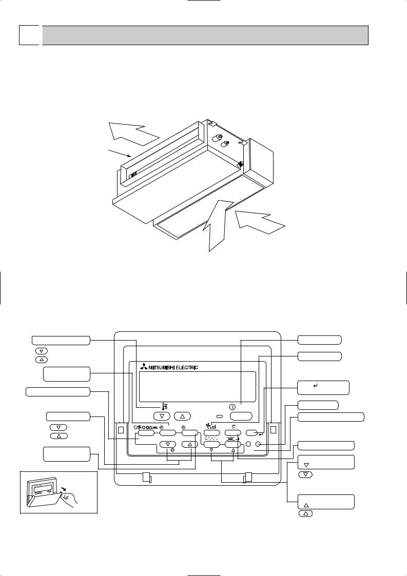
Wired remote controller
Once the controls are set, the same operation mode can be repeated by simply pressing the ON/OFF button.
● Operation buttons
Set Temperature buttons |
|
|
|
Down |
|
|
|
Up |
|
|
|
Timer Menu button |
|
|
|
(Monitor/Set button) |
|
|
|
Mode button (Return button) |
|
|
|
|
|
TEMP. |
|
Set Time buttons |
|
|
|
Back |
|
MENU |
ON/OFF |
Ahead |
BACK |
MONITOR/SET |
DAY |
|
|||
Timer On/Off button |
PAR-21MAA |
CLOCK |
|
|
|||
(Set Day button) |
|
|
|
Opening the |
|
|
|
door |
|
|
|
|
|
Start/Stop button |
||
|
|
Fan Speed button |
||
|
|
Filter |
button |
|
|
|
(<return sign> button) |
||
|
ON/OFF |
Test Run button |
||
|
|
|
|
|
|
|
Service button (Clear button) |
||
|
FILTER |
|
|
|
|
CHECK |
TEST |
|
|
OPERATION |
|
Airflow Up/Down button |
||
CLEAR |
|
|
|
|
|
|
Louver button |
||
|
|
( |
|
Operation button) |
|
|
|
|
To preceding operation |
|
|
|
|
number |
|
|
Ventilation button |
||
|
|
( |
Operation button) |
|
|
|
|
|
To next operation number |
2
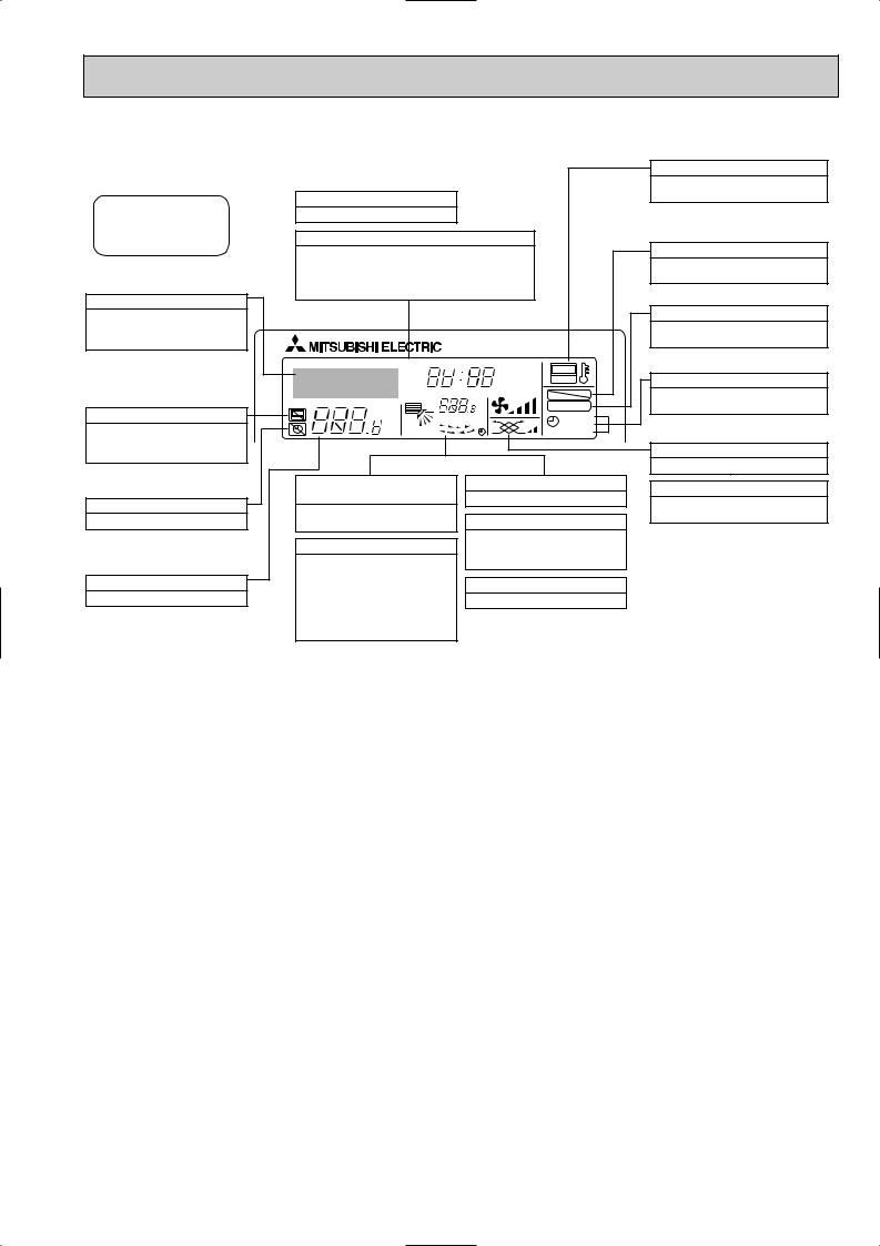
● Display
For purposes of this explanation, all parts of the display are shown as lit. During actual operation, only the relevant items will be lit.
Identifies the current operation
Shows the operating mode, etc.
*Multilanguage display is supported.
“Centrally Controlled” indicator
Indicates that operation of the remote controller has been prohibited by a master controller.
“Timer Is Off” indicator
Indicates that the timer is off.
Temperature Setting
Shows the target temperature.
Day-of-Week
Shows the current day of the week.
Time/Timer Display
Shows the current time, unless the simple or Auto Off timer is set.
If the simple or Auto Off timer is set, shows the time remaining.
TIME SUN MON TUE WED THU FRI SAT |
||
TIMER |
Hr |
ON |
AFTER |
AFTER |
OFF |
ERROR CODE |
|
FUNCTION |
˚F˚C |
|
FILTER |
˚F˚C |
|
|
|
WEEKLY |
|
ONLY1Hr. |
|
SIMPLE |
|
AUTO OFF |
|
Up/Down Air Direction indicator
The indicator  shows the direction of the outcoming airflow.
“One Hour Only” indicator
Displayed if the airflow is set to Low and downward during COOL or DRY mode. (Operation varies according to model.)
The indicator goes off after one hour, at which time the airflow direction also changes.
Room Temperature display
Shows the room temperature.
Louver display
Indicates the action of the swing louver. Does not appear if the louver is stationary.
 (Power On indicator)
Indicates that the power is on.
“Sensor” indication
Displayed when the remote controller sensor is used.
“Locked” indicator
Indicates that remote controller buttons have been locked.
“Clean The Filter” indicator
Comes on when it is time to clean the filter.
Timer indicators
The indicator comes on if the corresponding timer is set.
Fan Speed indicator
Shows the selected fan speed.
Ventilation indicator
Appears when the unit is running in Ventilation mode.
Caution
●Only the Power on indicator lights when the unit is stopped and power supplied to the unit.
●If you press a button for a feature that is not installed in the indoor unit, the remote controller will display the “Not Available” message.
If you are using the remote controller to operate multiple indoor units, this message will appear only if the feature is not present at the parent unit.
●When power is turned ON for the first time, it is normal that “PLEASE WAIT” is displayed on the room temperature indication (For max. 2minutes). Please wait until this “PLEASE WAIT” indication disappears then start the operation.
3

2 
 SPECIFICATIONS
|
|
Indoor model |
|
|
|
Function |
|
|
|
Power supply |
|
Capacity Air flow (High/Low) |
|||
Electrical |
data |
Power outlet |
|
Auxiliary heater |
|||
|
|
Running current 1 |
|
|
|
Power input Rated frequency |
|
|
|
Fan motor current 1 |
|
Fan |
motor |
Model |
|
Winding |
|||
|
|
||
|
|
resistance (at20:) |
|
|
|
Dimensions WoHoD |
|
|
|
Weight |
|
|
|
Air direction |
|
remarks |
Sound level (High/Low) |
||
Fan speed (High/Low) |
|||
|
|
||
Special |
Fan speed regulator |
||
External satatic pressure |
|||
|
|
||
Thermistor TH1 (at 25:)
Thermistor TH2 (at 25:)
Thermistor TH5 (at 25:)
|
SEZ-KA35VA.TH |
SEZ-KA50VA.TH |
||
|
Cooling |
Heating |
Cooling |
Heating |
|
|
Single phase |
Single phase |
|
|
|
230V, 50Hz |
230V, 50Hz |
|
K /h |
|
780/600 |
1020/720 |
|
A |
|
10 |
|
20 |
A |
|
0.40 |
|
0.55 |
W |
|
60 |
|
80 |
A(kW) |
|
— |
|
— |
A |
|
0.22 |
|
0.27 |
|
|
PK6V19-EF |
PK6V32-EF |
|
|
WHT-BLK : 257 BLK-BLU : 20 |
WHT-BLK : 166 |
BLK-BLU : 52 |
|
" |
BLU-YLW : 27 YLW-BRN : 14 |
BLU-YLW : 19 |
YLW-BRN : 8 |
|
|
BRN-RED : 51(at 26:) |
BRN-RED : 40(at 26:) |
||
mm |
1100o270o700 |
1100o270o700 |
||
kg |
|
33.5 |
|
33.5 |
|
|
1 |
|
1 |
dB(A) |
|
35/30 |
|
39/31 |
rpm |
|
770/630 |
840/640 |
|
|
|
3 |
|
3 |
Pa |
Std : 30 Max : 50 |
Std : 30 Max : 50 |
||
k" |
|
10 |
|
10 |
k" |
|
10 |
|
10 |
k" |
|
10 |
|
10 |
NOTE : Test conditions are based on ISO 5151
Cooling : Indoor |
D.B. 27: W.B. 19: |
Outdoor D.B. 35: W.B. 24: |
|
Heating : Indoor |
D.B. 20: W.B. 15: |
Outdoor D.B. 7: W.B. 6: Refrigerant piping length (one way): 5m
1 Measured under rated operating frequency.
Specifications and rating conditions of main electric parts
INDOOR UNIT
Item |
Model |
SEZ-KA35VA.TH SEZ-KA50VA.TH SEZ-KA60VA.TH SEZ-KA71VA.TH |
|
||
|
|
|
Indoor fan capacitor |
(C1) |
SEZ-KA35/50VA.TH : 2.5+ 440V SEZ-KA60VA.TH : 3.0+ 440V SEZ-KA71VA.TH : 4.0+ 440V |
Fuse |
(FUSE) |
250V 6.3A |
Varistor |
(ZNR) |
ERZV10D471 |
Terminal block |
(TB) |
TO OUTDOOR UNIT : 3P TO WIRED REMOTE CONTROLLER : 2P |
Indoor fan motor thermal fuse |
141:i3: |
|
4

|
|
Indoor model |
|
|
|
Function |
|
|
|
Power supply |
|
Capacity Air flow (High/Low) |
|||
Electrical |
data |
Power outlet |
|
Auxiliary heater |
|||
|
|
Running current 1 |
|
|
|
Power input Rated frequency |
|
|
|
Fan motor current 1 |
|
Fan |
motor |
Model |
|
Winding |
|||
|
|
||
|
|
resistance |
|
|
|
Dimensions WoHoD |
|
|
|
Weight |
|
|
|
Air direction |
|
remarks |
Sound level(High/Low) |
||
Fan speed(High/Low) |
|||
|
|
||
|
|
Fan speed regulator |
|
Special |
External satatic pressure |
||
Thermistor TH2 (at 25:) |
|||
|
|
Thermistor TH1 (at 25:) |
|
Thermistor TH5 (at 25:)
|
SEZ-KA60VA.TH |
SEZ-KA71VA.TH |
|||
|
Cooling |
Heating |
Cooling |
|
Heating |
|
|
||||
|
Single phase |
Single phase |
|||
|
230V, 50Hz |
230V, 50Hz |
|||
K /h |
1200/720 |
1200/720 |
|||
A |
|
20 |
|
20 |
|
A |
|
0.65 |
|
0.60 |
|
W |
|
100 |
|
130 |
|
A(kW) |
|
— |
|
— |
|
A |
|
0.39 |
|
0.51 |
|
|
PK6V50-EF |
PK4V60-EA |
|||
|
WHT-BLK : 103 |
BLK-BLU : 57 |
WHT-BLK : 108 |
|
BLK-BLU : 29 |
" |
BLU-YLW : 15 |
YLW-BRN : 7 |
BLU-YLW : 26 |
|
YLW-BRN : 14 |
|
BRN-RED : 29 (at 26:) |
BRN-RED : 34 (at 26:) |
|||
mm |
1100o270o700 |
1100o270o700 |
|||
kg |
|
33.5 |
|
35 |
|
|
|
1 |
|
1 |
|
dB(A) |
43/32 |
43/32 |
|||
rpm |
890/660 |
1050/690 |
|||
|
|
3 |
|
3 |
|
Pa |
Std : 30 Max : 50 |
Std : 30 Max : 50 |
|||
k" |
|
10 |
|
10 |
|
k" |
|
10 |
|
10 |
|
k" |
|
10 |
|
10 |
|
NOTE : Test conditions are based on ISO 5151
Cooling : Indoor |
D.B. 27: W.B. 19: |
Outdoor D.B. 35: W.B. 24: |
|
Heating : Indoor |
D.B. 20: W.B. 15: |
Outdoor D.B. 7: W.B. 6: Refrigerant piping length (one way): 5m
1 Measured under rated operating frequency.
5

NOISE CRITERION CURVES
<50Hz>
SEZ-KA35VA.TH |
NOTCH SPL(dB) LINE |
|
|
|
|
|
|
|
High |
35 |
|
|
|
|
|
|
|
|
Low |
30 |
|
|
90 |
|
|
|
|
|
|
|
|
bar) |
80 |
|
|
|
|
|
|
|
|
= 0.0002 |
70 |
|
|
|
|
|
|
|
|
dB |
|
|
|
|
|
|
|
NC-70 |
|
|
|
|
|
|
|
|
|
||
dB (0 |
60 |
|
|
|
|
|
|
|
|
LEVEL, |
|
|
|
|
|
|
|
|
|
|
|
|
|
|
|
|
|
NC-60 |
|
|
|
|
|
|
|
|
|
|
|
PRESSURE |
50 |
|
|
|
|
|
|
|
|
|
|
|
|
|
|
|
|
NC-50 |
|
40 |
|
|
|
|
|
|
|
|
|
SOUND |
|
|
|
|
|
|
|
|
|
|
|
|
|
|
|
|
|
NC-40 |
|
|
|
|
|
|
|
|
|
|
|
BAND |
30 |
|
|
|
|
|
|
|
|
|
|
|
|
|
|
|
|
NC-30 |
|
|
|
|
|
|
|
|
|
|
|
OCTAVE |
20 |
APPROXIMATE |
|
|
|
|
|
|
|
|
TERESHOLD OF |
|
|
|
|
|
|
||
|
HEARING FOR |
|
|
|
|
|
NC-20 |
||
|
|
CONTINUOUS |
|
|
|
|
|
||
|
|
|
|
|
|
|
|
||
|
|
NOISE |
|
|
|
|
|
|
|
|
10 |
63 |
125 |
250 |
500 |
1000 |
2000 |
4000 |
8000 |
|
|
||||||||
BAND CENTER FREQUENCIES, Hz
<50Hz>
SEZ-KA50VA.TH |
NOTCH SPL(dB) LINE |
|
|
|
|
|
|
|
High |
39 |
|
|
|
|
|
|
|
|
Low |
31 |
|
|
90 |
|
|
|
|
|
|
|
|
bar) |
80 |
|
|
|
|
|
|
|
|
= 0.0002 |
70 |
|
|
|
|
|
|
|
|
dB |
|
|
|
|
|
|
|
NC-70 |
|
|
|
|
|
|
|
|
|
||
dB (0 |
60 |
|
|
|
|
|
|
|
|
LEVEL, |
|
|
|
|
|
|
|
|
|
|
|
|
|
|
|
|
|
NC-60 |
|
|
|
|
|
|
|
|
|
|
|
PRESSURE |
50 |
|
|
|
|
|
|
|
|
|
|
|
|
|
|
|
|
NC-50 |
|
40 |
|
|
|
|
|
|
|
|
|
SOUND |
|
|
|
|
|
|
|
|
|
|
|
|
|
|
|
|
|
NC-40 |
|
|
|
|
|
|
|
|
|
|
|
BAND |
30 |
|
|
|
|
|
|
|
|
|
|
|
|
|
|
|
|
NC-30 |
|
|
|
|
|
|
|
|
|
|
|
OCTAVE |
20 |
APPROXIMATE |
|
|
|
|
|
|
|
|
TERESHOLD OF |
|
|
|
|
|
|
||
|
HEARING FOR |
|
|
|
|
|
NC-20 |
||
|
|
CONTINUOUS |
|
|
|
|
|
||
|
|
|
|
|
|
|
|
||
|
|
NOISE |
|
|
|
|
|
|
|
|
10 |
63 |
125 |
250 |
500 |
1000 |
2000 |
4000 |
8000 |
|
|
||||||||
BAND CENTER FREQUENCIES, Hz
SEZ-KA60VA.TH |
|
|
|
<50Hz> |
|
|
|||||
|
NOTCH |
SPL(dB) |
LINE |
|
|
||||||
SEZ-KA71VA.TH |
|
|
High |
43 |
|
|
|
||||
|
|
Low |
32 |
|
|
|
|||||
|
|
|
|
|
|
|
|
|
|
||
|
90 |
|
|
|
|
|
|
|
|
|
|
bar) |
80 |
|
|
|
|
|
|
|
|
|
UNIT |
= 0.0002 |
70 |
|
|
|
|
|
|
|
NC-70 |
|
|
dB (0 dB |
|
|
|
|
|
|
|
|
|
||
|
|
|
|
|
|
|
|
|
|
||
60 |
|
|
|
|
|
|
|
|
External static |
|
|
LEVEL, |
|
|
|
|
|
|
|
NC-60 |
1.5m |
||
|
|
|
|
|
|
|
|
pressure 30Pa |
|||
|
|
|
|
|
|
|
|
|
|
||
PRESSURE |
|
|
|
|
|
|
|
|
|
|
|
50 |
|
|
|
|
|
|
|
|
|
|
|
|
|
|
|
|
|
|
|
|
|
|
|
|
|
|
|
|
|
|
|
|
NC-50 |
|
|
SOUND |
40 |
|
|
|
|
|
|
|
|
|
MICROPHONE |
|
|
|
|
|
|
|
|
NC-40 |
|
|
|
BAND |
|
|
|
|
|
|
|
|
|
|
|
30 |
|
|
|
|
|
|
|
|
|
|
|
|
|
|
|
|
|
|
|
|
|
|
|
OCTAVE |
|
|
|
|
|
|
|
|
NC-30 |
|
|
20 |
HEARING FOR |
|
|
|
|
|
|
|
|
||
|
APPROXIMATE |
|
|
|
|
|
|
|
|
||
|
|
TERESHOLD OF |
|
|
|
|
|
|
|
|
|
|
|
CONTINUOUS |
|
|
|
|
|
NC-20 |
|
|
|
|
|
|
|
|
|
|
|
|
|
||
|
|
NOISE |
|
|
|
|
|
|
|
|
|
|
10 |
63 |
125 |
250 |
500 |
1000 |
2000 |
4000 |
8000 |
|
|
|
|
|
|
||||||||
BAND CENTER FREQUENCIES, Hz
NOTE: The sound level is measured in an anechoic room where echoes are few, when compressor stops. The sound may be bigger than displayed level under actual installation condition by surrounding echoes. The sound level can be higher by about 2 dB than the displayed level during cooling and heating operation.
6

INDOOR FAN PERFORMANCE AND CORRECTED AIR FLOW
SEZ-KA35VA.TH
Fan Performance
Recommended range
80
pressure(Pa) 60 staticExternal 0.1mmAq)= (1Pa
40
20
0 |
5 |
7 |
10 |
15 |
20 |
25 |
|
Air flow (K/X)
Correction factor
Correction factor
Corrected Air flow |
Capacity |
Cooling |
Input |
|
1.1
1.0
0.9
0.8
5 |
10 |
15 |
20 |
25 |
Air flow (K/X)
Heating
1.3
1.2
1.1
1.0
0.9
0.8
5 |
10 |
15 |
20 |
25 |
Air flow (K/X)
SEZ-KA50VA.TH
Fan Performance
Recommended range
80
pressure(Pa) 60 staticExternal 0.1mmAq)= (1Pa
40
20
0 |
5 |
10 |
15 |
20 |
25 |
|
Air flow (K/X)
|
|
Corrected Airflow |
|
|
Capacity |
||||||
|
|
|
|
||||||||
|
|
Cooling |
|
|
|
|
|
|
Input |
||
|
1.1 |
|
|
|
|
|
|
|
|
||
factor |
|
|
|
|
|
|
|
|
|
|
|
|
|
|
|
|
|
|
|
|
|
||
1.0 |
|
|
|
|
|
|
|
|
|
|
|
|
|
|
|
|
|
|
|
|
|
||
Correction |
0.9 |
|
|
|
|
|
|
|
|
|
|
|
|
|
|
|
|
|
|
|
|
|
|
|
0.8 |
|
|
|
|
|
|
|
|
|
|
|
|
|
10 |
15 |
20 |
25 |
|||||
|
5 |
||||||||||
|
|
|
|
Air flow (K/X) |
|
|
|
|
|||
|
1.2 |
Heating |
|
|
|
|
|
|
|||
|
|
|
|
|
|
|
|
|
|
|
|
|
|
|
|
|
|
|
|
|
|
|
|
factor |
1.1 |
|
|
|
|
|
|
|
|
|
|
|
|
|
|
|
|
|
|
|
|
||
1.0 |
|
|
|
|
|
|
|
|
|
|
|
|
|
|
|
|
|
|
|
|
|
||
Correction |
0.9 |
|
|
|
|
|
|
|
|
|
|
|
|
|
|
|
|
|
|
|
|
|
|
|
0.8 |
|
|
|
|
|
|
|
|
|
|
|
|
|
10 |
15 |
20 |
25 |
|||||
|
5 |
||||||||||
Air flow (K/X)
7

INDOOR FAN PERFORMANCE AND CORRECTED AIR FLOW
SEZ-KA60VA.TH
Fan Performance
Recommended range
80
pressure(Pa) 60 staticExternal 0.1mmAq)= (1Pa
40
20
0 |
5 |
10 |
15 |
20 |
25 |
|
Air flow (K/X)
Correction factor
Correction factor
Corrected Air flow |
Capacity |
Cooling |
Input |
|
1.1
1.0
0.9
0.8
10 |
15 |
20 |
25 |
30 |
Air flow (K/X)
Heating
1.3
1.2
1.1
1.0
0.9
10 |
15 |
20 |
25 |
30 |
Air flow (K/X)
SEZ-KA71VA.TH
Fan Performance
Recommended range
80
pressure(Pa) 60 staticExternal 0.1mmAq)= (1Pa
40
20
0 |
5 |
10 |
15 |
20 |
25 |
|
Air flow (K/X)
Correction factor
Correction factor
Corrected Air flow |
Capacity |
Cooling |
Input |
|
1.1
1.0
0.9
0.8
10 |
15 |
20 |
25 |
30 |
Air flow (K/X)
Heating
1.3
1.2
1.1
1.0
0.9
10 |
15 |
20 |
25 |
30 |
Air flow (K/X)
8

3 OUTLINES AND DIMENSIONS
SEZ-KA35VA.TH SEZ-KA50VA.TH SEZ-KA60VA.TH SEZ-KA71VA.TH
Air inlet (rear side) dimensions
|
|
42 |
930 |
|
|
|
(Inlet size) |
240 |
120 |
|
|
|
12.5 |
77.5 100 |
7x100=700 |
|
29 |
955 |
|
|
|
24-{2.9 holes
In case of bottom side suction, mount the PLATE (A) on the rear side.
After installation, remove the transportation support PLATE (B).
215 |
(Inlet size) |
25 |
|
PLATE (B) x 2
5027 |
1016 |
150 |
450 |
|
Air inlet |
|
Electrical parts box |
|
(rear side) |
|
|
|
w Select the either |
77 |
150 |
|
back side or bottom side. |
|
|
|
|
|
50
Unit : mm
Air inlet (bottom side) dimensions
PLATE (A)
240 |
120 |
930 |
215 |
(Inletsize) |
|
51 |
|
|
|
|
|
(Inlet size) |
|
|
12.5 |
39 77.5 100 |
7x100=700 |
25 |
|
|
|
|
||
|
|
955 |
|
|
1000 |
680 |
350 |
Suspension bolt pitch |
|
|
38 |
50 |
|
|
60 |
|
|
|
|
(10) |
Suspension bolt M10 or 3/8 (procure locally)
|
|
|
|
|
|
|
|
24-{2.9 holes |
|
|
|
|
|
|
600 |
|
|
|
|
|
|
|
700 |
|
Access door |
|
|
|
|
|
|
|
|
|
|
|
|
||
|
|
|
|
|
Service space |
|
|
|
|
|
|
|
|
|
(It is necessary to maintain a working |
|
|||
|
|
|
|
|
service area from the ceiling.) |
|
|
||
40 |
100 |
7x100=700 |
|
|
|
|
|
|
|
50 |
|
880 |
Air outlet duct flange |
|
|
|
|
|
|
|
9 x 2-{2.9 holes |
|
|
|
|
|
|||
|
|
|
|
|
|
|
|
||
|
|
Air outlet |
|
|
|
|
|
|
|
|
|
1070 |
|
|
|
|
|
|
|
|
|
Suspension bolt pitch |
more |
|
|
|
|
Refrigerent pipe (gas) |
|
|
|
|
|
|
|
|
|
||
|
|
(1070) |
|
|
|
|
Refrigerent pipe (liquid) |
||
|
|
or |
|
|
|
|
|||
|
|
|
|
(10) |
50 |
|
|
||
|
|
(Suspension bolt pitch) |
20 |
|
|
|
Terminal block |
||
|
|
|
25 |
32.5 |
|
Wiring entry |
|||
|
|
|
|
20 |
|||||
|
|
|
|
|
|||||
|
|
|
|
|
|
|
|
|
|
|
|
|
30 |
Electrical parts box |
170 |
100 |
|
|
|
|
|
|
270 |
|
|
|
|||
|
|
|
|
75 |
|
|
|
|
|
1100
Air inlet |
Access door |
|
(bottom side) |
||
|
w Select the either back side or bottom side.
2x2-{2.9 holes
Air outlet duct flange
Models
SEZ-KA35VA
SEZ-KA50VA
SEZ-KA60VA
SEZ-KA71VA
108 |
25 |
Electrical parts box |
94 |
80 |
Drain plug R1 (male) |
|
350 |
|
|
|
|
Refrigerent pipe |
Refrigerent pipe |
|
(liquid) |
(gas) |
|
{6.35mm |
{9.52mm |
|
flared connection |
flared connection |
|
1/4F |
|
3/8F |
{6.35mm |
{12.7mm |
|
flared connection |
flared connection |
|
1/4F |
|
1/2F |
{6.35mm |
{15.88mm |
|
flared connection |
flared connection |
|
1/4F |
|
5/8F |
{9.52mm |
{15.88mm |
|
flared connection |
flared connection |
|
3/8F |
|
5/8F |
9

4 
 WIRING DIAGRAM
SEZ-KA35VA.TH
SEZ-KA50VA.TH
SEZ-KA60VA.TH
SEZ-KA71VA.TH
MF
WHT |
ORN |
RED |
BLK |
YLW |
BLU |
BRN |
|
1 |
2 |
3 |
4 |
5 |
6 |
7 |
8 |
1 |
2 |
3 |
4 |
5 |
6 |
7 |
8 |
ORN |
|
|
|
YLW |
BLU |
|
|
C1 |
RED |
|
<fig:w1>
MODELS |
SW2 |
BLK |
BLU |
BRN |
WHT |
RED |
WHT |
|
RED |
BLU |
|
|
|
|
|
|
|
|
|
|
|
|
|
|
|
||
KA35 |
ON |
|
|
|
WHT |
|
|
RED |
|
|
|
ORN |
|
OFF |
1 2 |
3 4 |
5 6 |
1 |
3 |
1 |
3 |
|
|
||||
|
(POWER) |
||||||||||||
|
1 2 3 4 5 |
7 (FAN) |
(POWER |
|
|||||||||
|
|
|
|
FAN |
|
|
BOARD) |
|
|
|
CND |
|
|
|
|
|
|
|
|
|
|
|
|
|
|||
KA50 |
ON |
|
|
|
|
|
|
CNDK |
|
|
|
|
|
OFF |
|
|
|
|
|
|
FUSE |
|
|
|
|
|
|
|
1 2 3 4 5 |
|
|
|
|
|
|
|
|
|
|
|
|
KA60 |
ON |
|
|
|
|
|
|
|
|
|
|
|
|
OFF |
|
|
|
|
|
|
|
|
|
|
|
|
|
|
1 2 3 4 5 |
|
|
|
|
|
|
ZNR |
|
|
|
|
|
|
ON |
X6 |
X5 |
X4 |
|
|
|
|
|
|
|
|
|
|
|
|
|
|
|
|
|
|
|
||||
KA71 |
OFF |
|
|
|
|
|
|
|
|
|
|
|
|
|
1 2 3 4 5 |
X6 |
X5 |
X4 |
|
|
|
|
|
|
|
|
|
|
|
|
|
|
|
|
|
|
|
|
|||
|
SWE |
SW3 |
|
|
|
|
|
|
|
|
|
|
|
|
ON |
ON |
|
|
|
|
LED3 |
|
|
|
|
|
|
|
OFF |
OFF |
|
|
|
|
|
|
|
|
|
||
|
|
|
|
|
|
|
|
|
|
|
|
||
|
1 2 3 4 5 |
|
|
|
|
|
|
|
|
|
|
|
|
|
|
|
|
|
|
|
|
|
|
|
|
|
|
|
SW2 |
CN2L |
|
|
|
|
|
|
|
|
|
||
|
|
|
|
|
|
|
BLK |
RED |
|||||
|
ON |
|
|
|
|
|
|
|
|||||
|
|
|
|
|
|
|
(2 PHASE) (INTAKE) |
||||||
|
OFF |
|
|
|
|
|
|
||||||
|
|
|
|
|
|
|
|
CN29 |
CN20 |
||||
|
1 2 3 4 5 |
|
|
|
|
|
|
||||||
|
|
|
|
|
|
|
|
|
|
|
|
||
|
|
CN32 |
CN51 |
CN41 |
CN90 |
|
|
|
1 |
2 |
1 |
2 |
|
|
|
|
|
|
|
|
|
|
|||||
See fig:w1
TH5 TH1
[LEGEND]
SYMBOL |
NAME |
SYMBOL |
NAME |
|
P.B |
INDOOR POWER BOARD |
C1 |
CAPACITOR(FAN MOTOR) |
|
I.B |
INDOOR CONTROLLER BOARD |
MF |
FAN MOTOR |
|
|
CN2L |
CONNECTOR(LOSSNAY) |
TB4 |
TERMINAL BLOCK(INDOOR/OUTDOOR CONNECTING LINE) |
|
CN32 |
CONNECTOR(REMOTE SWITCH) |
|
TERMINAL BLOCK(REMOTE CONTROLLER |
|
CN41 |
CONNECTOR(HA TERMINAL-A) |
TB15 |
TRANSMISSION LINE) |
|
|
|||
|
|
|
|
|
|
CN51 |
CENTRALLY CONTROL |
TH1 |
ROOM TEMP.THERMISTOR |
|
CN90 |
CONNECTOR(WIRELESS) |
(0°C/15kΩ ,25°C/5.4kΩ DETECT) |
|
|
|
|||
|
FUSE |
FUSE(T6.3AL250V) |
TH2 |
PIPE TEMP.THERMISTOR/LIQUID |
|
LED1 |
POWER SUPPLY(I.B) |
(0°C/15kΩ ,25°C/5.4kΩ DETECT) |
|
|
|
|||
|
LED2 |
POWER SUPPLY(I.B) |
TH5 |
COND./EVA.TEMP.THERMISTOR |
|
|
|
(0°C/15kΩ ,25°C/5.4kΩ DETECT) |
|
|
LED3 |
TRANSMISSION(INDOOR-OUTDOOR) |
||
|
|
|||
|
SW2 |
SWITCH(CAPACITY CODE) |
|
|
|
SW3 |
SWITCH(MODE SELECTION) |
|
|
|
SWE |
SWITCH(EMERGENCY OPERATION) |
|
|
|
|
|
|
|
|
X4 |
RELAY(FAN MOTOR LL) |
|
|
|
|
|
|
|
|
X5 |
RELAY(FAN MOTOR Lo) |
|
|
|
X6 |
RELAY(FAN MOTOR Hi) |
|
|
|
ZNR |
VARISTOR |
|
|
TB4
|
|
|
|
|
S1 |
|
|
|
|
|
|
|
|
S2 |
TO OUTDOOR |
||
|
|
|
|
|
S3 |
|||
|
|
|
|
|
UNIT |
|
||
|
|
|
|
|
|
|
||
|
|
|
|
|
|
|
|
P.B |
|
|
|
|
|
|
1 2 |
3 |
AC220-240V |
|
|
|
|
|
|
|
|
CNSK(RED) |
|
ORN |
BLU |
I.B |
|
|
|
|
|
|
1 |
3 |
|
|
|
|
|
TRANS |
|
BLU |
|
|
|
|
|
|
|
|
(CONTROL) |
|
|
|
|
|
||
|
CN3C |
|
|
|
|
|
|
|
|
|
|
|
|
|
1 |
2 |
DC13.1V |
|
|
|
|
|
|
|
|
CN2S(WHT) |
|
|
WHT |
|
1 |
BLK |
|
|
|
|
(POWER |
|
WHT |
|
|
|
||
|
BOARD) |
2 |
|
|
|
|||
|
CN2D |
|
|
|
|
|
||
|
|
|
|
|
|
|
||
|
|
LED1 |
|
|
|
|
||
|
LED2 |
|
|
|
|
|
|
|
WHT |
BLU |
|
|
|
|
|
||
(LIQUID) |
(REMOCON) |
|
|
|
||||
CN21 |
CN22 |
|
|
|
|
|||
1 |
2 |
1 |
2 |
|
|
|
|
|
|
|
BLU |
BLU |
|
|
|
|
|
|
|
|
|
TB15 |
|
|
|
|
|
|
|
|
|
1 |
TO MA-REMOTE |
||
|
|
|
|
|
|
|||
TH2 |
|
|
|
2 }CONTROLLERDC8.7-13V |
||||
NOTES: 1.Since the outdoor side electric wiring may change be sure to check the outdoor unit electric wiring for servicing.
2.Indoor and outdoor connecting wires are made with polarities,make
wiring matching terminal numbers(S1,S2,S3). |
|
|
|
|
|
|
|
||
3.Symbols used in wiring diagram above are, |
:Connector, |
:Terminal(block). |
|||||||
4.Since the indoor fan motor(MF) is connected with 50Hz power, |
|
|
|
||||||
if 60Hz power is used, change the wiring connection shown in |
|
|
|
||||||
fig:w2. |
|
<fig:w2> |
|
|
|
|
|
|
|
|
Indoor Fan Motor(MF) |
|
|
|
50 |
|
YELLOW |
||
|
|
|
|
|
|
|
|
|
|
|
|
|
|
|
|
|
|
|
|
|
for 60Hz |
BLUE |
|
|
60 |
|
|
BLUE |
|
|
|
|
|
|
|||||
wFor details on how to operate self-diagnosis, refer to the technical manuals etc.
10
 Loading...