


PDFY-P20VM-A
Mitsubishi PDFY-P20VM-A, PDFY-P25VM-A, PDFY-P32VM-A, PDFY-P40VM-A, PDFY-P50VM-A Service Manual
...
TECHNICAL & SERVICE MANUAL
Air-Conditioners For Building Application
<Indoor unit>
PDFY-P20VM-A,PDFY-P63VM-A
PDFY-P25VM-A,PDFY-P71VM-A
PDFY-P32VM-A,PDFY-P80VM-A
PDFY-P40VM-A,PDFY-P100VM-A
PDFY-P50VM-A,PDFY-P125VM-A
2001
Models
Ceiling Concealed Built-in
Series PDFY
CONTENTS
SAFETY PRECAUTIONS·························1
1. FEATURES············································3
2. PART NAMES AND FUNCTIONS········4
3. SPECIFICATION ···································6
4. OUTLINES AND DIMENSIONS············8
5.WIRING DIAGRAM ·····························10
6.
REFRIGERANT SYSTEM DIAGRAM
····12
7.TROUBLE SHOOTING························13
8. DISASSEMBLY PROCEDURE···········18
For use with the R407C & R22
1
- Inadequate connection and fastening may generate heat and
cause a fire.
• Prepare for typhoons and other strong winds and earthquakes
and install the unit at the specified place.
- Improper installation may cause the unit to topple and result in
injury.
• Always use an air cleaner , humidifier, electric heater, and other
accessories specified by Mitsubishi Electric.
- Ask an authorized technician to install the accessories. Improper
installation by the user may result in water leakage, electric shock,
or fire.
• Never repair the unit. If the air conditioner must be repaired,
consult the dealer.
- If the unit is repaired improperly, water leakage , electric shoc k, or
fire may result.
• Do not touch the heat exchanger fins.
- Improper handling may result in injury.
• If refrigerant gas leaks during installation work, ventilate the
room.
- If the refrigerant gas comes into contact with a flame, poisonous
gases will be released.
• Install the air conditioner according to this Installation Manual.
- If the unit is installed improperly, water leakage , electric shock, or
fire may result.
• Have all electric work done by a licensed electrician according
to “Electric Facility Engineering Standard” and “Interior Wire
Regulations”and the instructions given in this manual and al-
ways use a special circuit.
- If the power source capacity is inadequate or electric work is per-
formed improperly, electric shoc k and fire may result.
• Securely install the cover of control box and the panel.
- If the cover and panel are not installed properly, dust or water
may enter the outdoor unit and fire or electric shock may result.
• When installing and moving the air conditioner to another site,
do not charge the it with a refrigerant different from the refrig-
erant (R407C or R22) specified on the unit.
- If a different refrigerant or air is mixed with the original refrigerant,
the refrigerant cycle may malfunction and the unit may be dam-
aged.
• If the air conditioner is installed in a small room, measures
must be taken to prevent the refrigerant concentration from
exceeding the safety limit even if the refrigerant should leak.
- Consult the dealer regarding the appropr iate measures to pre-
vent the safety limit from being exceeded. Should the refrigerant
leak and cause the safety limit to be exceeded, hazards due to
lack of oxygen in the room could result.
• When moving and reinstalling the air conditioner, consult the
dealer or an authorized technician.
- If the air conditioner is installed improperly, water leakage, elec-
tric shock, or fire may result.
• After completing installation work, make sure that refrigerant
gas is not leaking.
- If the refrigerant gas leaks and is exposed to a fan heater, stove,
oven, or other heat source, it may generate noxious gases.
• Do not reconstruct or change the settings of the protection
devices.
- If the pressure switch, thermal switch, or other protection device
is shorted and operated forcibly , or parts other than those specified
by Mitsubishi Electric are used, fire or explosion may result.
1. Before installation and electric work
s Before installing the unit, make sure you read all the
“Safety precautions”.
s The “Safety precautions” provide very important
points regarding safety. Make sure you follow them.
s This equipment may not be applicable to EN61000-3-
2: 1995 and EN61000-3-3: 1995.
s
s Please report to or take consent by the supply au-
thority before connection to the system.
Symbols used in the text
Warning:
Describes precautions that should be observed to prevent danger
of injury or death to the user.
Caution:
Describes precautions that should be observed to prevent damage
to the unit.
Symbols used in the illustrations
: Indicates an action that must be avoided.
: Indicates that important instructions must be followed.
: Indicates a part which must be grounded.
: Indicates that caution should be taken with rotating parts. (This
symbol is displayed on the main unit label.) <Color: Yellow>
: Beware of electric shock (This symbol is displayed on the main
unit label.) <Color: Yellow>
Warning:
Carefully read the labels affixed to the main unit.
Warning:
• Ask the dealer or an authorized technician to install the air con-
ditioner.
- Improper installation by the user may result in water leakage, elec-
tric shock, or fire.
• Install the air unit at a place that can withstand its weight.
- Inadequate strength may cause the unit to fall down, resulting in
injuries.
• Use the specified cables for wiring. Make the connections se-
curely so that the outside force of the cable is not applied to the
terminals.
This equipment may have an adverse effect equip-
ment on the same electrical supply system.
SAFETY PRECAUTIONS

2
2. Precautions for devices that use
R407C refrigerant
Caution:
• Do not use the existing refrigerant piping.
- The old refrigerant and refrigerator oil in the existing piping con-
tains a large amount of chlorine which may cause the refrigerator
oil of the new unit to deteriorate.
• Use refrigerant piping made of C1220 (CU-DHP) phosphorus
deoxidized copper as specified in the *JIS H3300 “Copper and
copper alloy seamless pipes and tubes”. In addition, be sure
that the inner and outer surfaces of the pipes are clean and
free of hazardous sulphur, oxides, dust/dirt, shaving particles,
oils, moisture, or any other contaminant.
- Contaminants on the inside of the refrigerant piping may cause
the refrigerant residual oil to deteriorate.
*JIS: Japanese Industrial Standard
• Store the piping to be used during installation indoors and keep
both ends of the piping sealed until just before brazing. (Store
elbows and other joints in a plastic bag.)
- If dust, dirt, or water enters the refrigerant cycle, deterioration of
the oil and compressor trouble may result.
• Use ester oil, ether oil or alkylbenzene (small amount) as the
refrigerator oil to coat flares and flange connections.
- The refrigerator oil will degrade if it is mixed with a large amount of
mineral oil.
• Use liquid refrigerant to fill the system.
- If gas refr igerant is used to seal the system, the composition of
the refrigerant in the cylinder will change and performance may
drop.
• Do not use a refrigerant other than R407C.
- If another refrigerant (R22, etc.) is used, the chlorine in the refrig-
erant may cause the refrigerator oil to deteriorate.
• Use a vacuum pump with a reverse flow check valve..
- The vacuum pump oil may flow bac k into the refrigerant cycle and
cause the refrigerator oil to deteriorate.
• Do not use the following tools that are used with con ventional
refrigerants.
(Gauge manifold, charge hose, gas leak detector, reverse flow
check valve, refrigerant charge base, vacuum gauge, refriger-
ant recovery equipment)
- If the conventional refrigerant and refrigerator oil are mixed in the
R407C, the refrigerant may deteriorated.
- If water is mixed in the R407C, the refrigerator oil ma y deteriorate.
- Since R407C does not contain any chlorine, gas leak detectors
for conventional refrigerants will not react to it.
• Do not use a charging cylinder.
- Using a charging cylinder may cause the refrigerant to deteriorate.
• Be especially careful when managing the tools.
- If dust, dirt, or water gets in the refrigerant cycle, the refrigerant
may deteriorate.
3
PDFY-P20VM-A
PDFY-P25VM-A
PDFY-P32VM-A
PDFY-P40VM-A
PDFY-P50VM-A
PDFY-P63VM-A
PDFY-P80VM-A
PDFY-P100VM-A
PDFY-P125VM-A
2.2/ 2.5
2.8/ 3.2
3.6/ 4.0
4.5/ 5.0
5.6/ 6.3
7.1/ 8.0
8.0/ 9.0
9.0/ 10.0
11.2/ 12.5
14.0/ 16.0
PDFY-P71VM-A
Ceiling Concealed Built-in
Series PDFY
Models
Cooling capacity/Heating capacity
kW
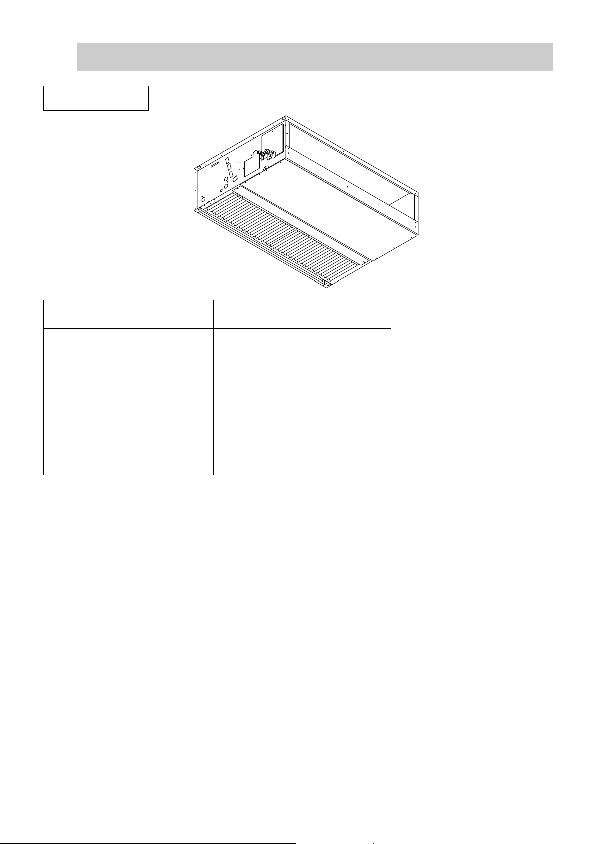
FEATURES1
Indoor unit
4
●
●
●
Remote
Indoor (Main) Unit
controller
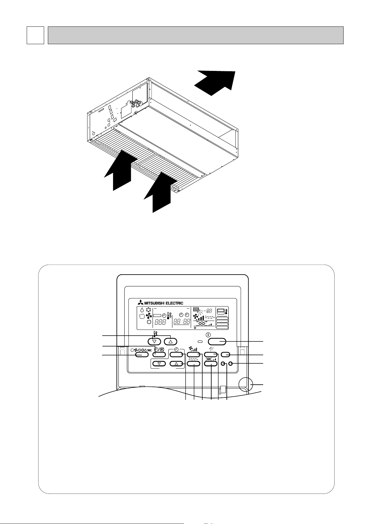
● Operation buttons
[PAR-20MAA]
Once the controls are set, the same operation mode can
be repeated by simply pressing the ON/OFF button.
PAR-20MAA
ON/OFF
CENTRALLY CONTROLLED
ERROR CODE
CLOCK
ON OFF
˚C
CHECK
CHECK MODE
FILTER
TEST RUN
FUNCTION
˚C
1Hr.
NOT AVAILABLE
STAND BY
DEFROST
FILTER
CHECK TEST
TEMP.
TIMER SET
1
2
3
4 56879
0
C
A
B
1 [Room temperature adjustment] Button
2 [Timer/continuous] Button
3 [Selecting operation] Button
4 [Time selection] Button
[Time-setting] Button
5 [Louver] Button
6 [Fan speed adjustment] Button
7 [Up/down airflow direction] Button
8 [Ventilation] Button
9 [Checking/built-in] Button
0 [Test run] Button
A [Filter] Button
B [ON/OFF] Button
C Position of built-in room temperature
•Never expose the remote controller to direct sunlight. Doing so can result in the erroneous measure-
ment of room temperature.
•Never place any obstacle around the lower right-hand section of the remote controller.Doing so can
result in the erroneous measurement of room temperature.
PART NAMES AND FUNCTIONS2
Air outlet
Air inlet
5
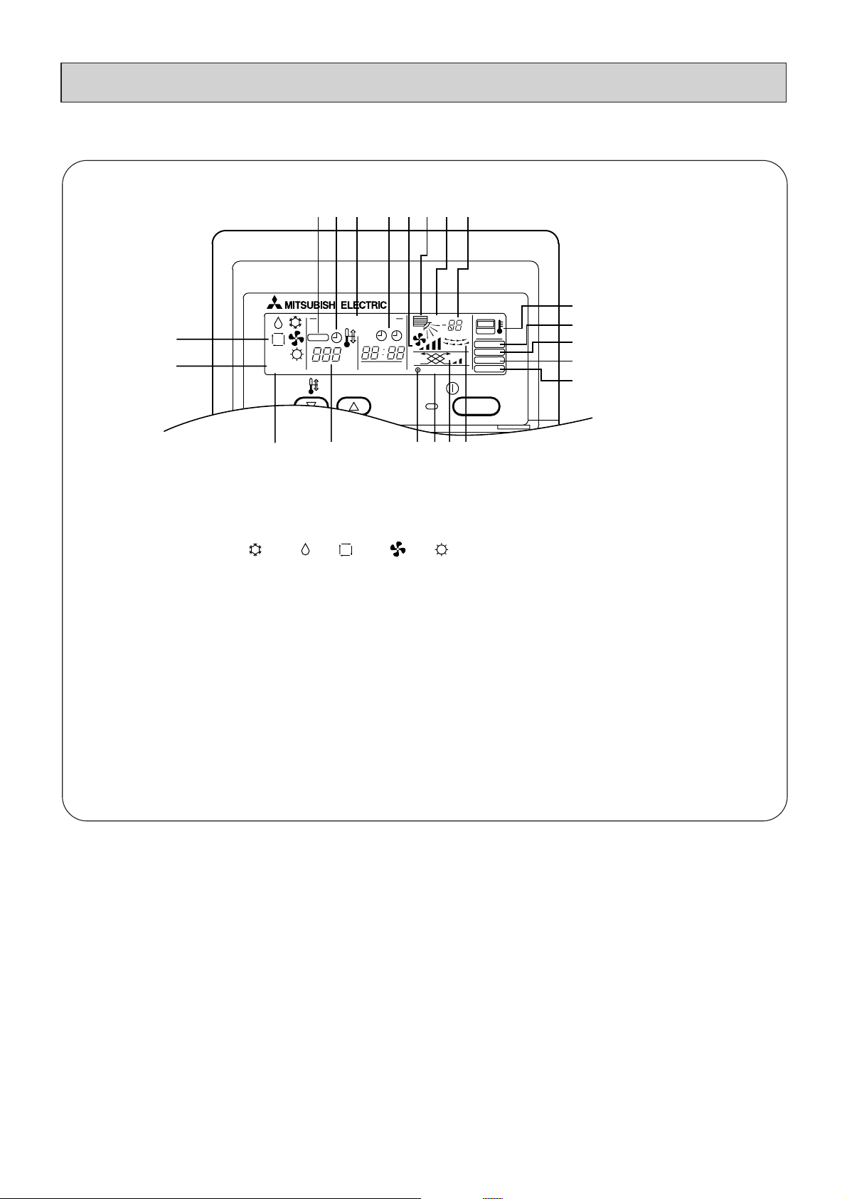
● Display
ON/OFF
CENTRALLY CONTROLLED
ERROR CODE
CLOCK
ON OFF
˚C
CHECK
CHECK MODE
FILTER
TEST RUN
FUNCTION
˚C
1Hr.
NOT AVAILABLE
STAND BY
DEFROST
TEMP.
ABCD
E
F
HIKLJ
M
P
N
O
R
SQTU
G
(A) Current time/Timer
(B) Centralized control
(C) Timer ON
(D) Abnormality occurs
(E) Operation mode: COOL, DRY, AUTO, FAN, HEAT
(F) Preparing for Heating mode
(G) Defrost mode
(H) Set temperature
(I) Power ON
(J) Louver
(K) Not available function
(L) Ventilation
(M) Function setting mode
(N) Test run mode
(O) Error check mode
(P) Filter sign
(Q) Set effective for 1 hr.
(R) Sensor position
(S) Room temperature
(T) Airflow
(U) Fan speed
6
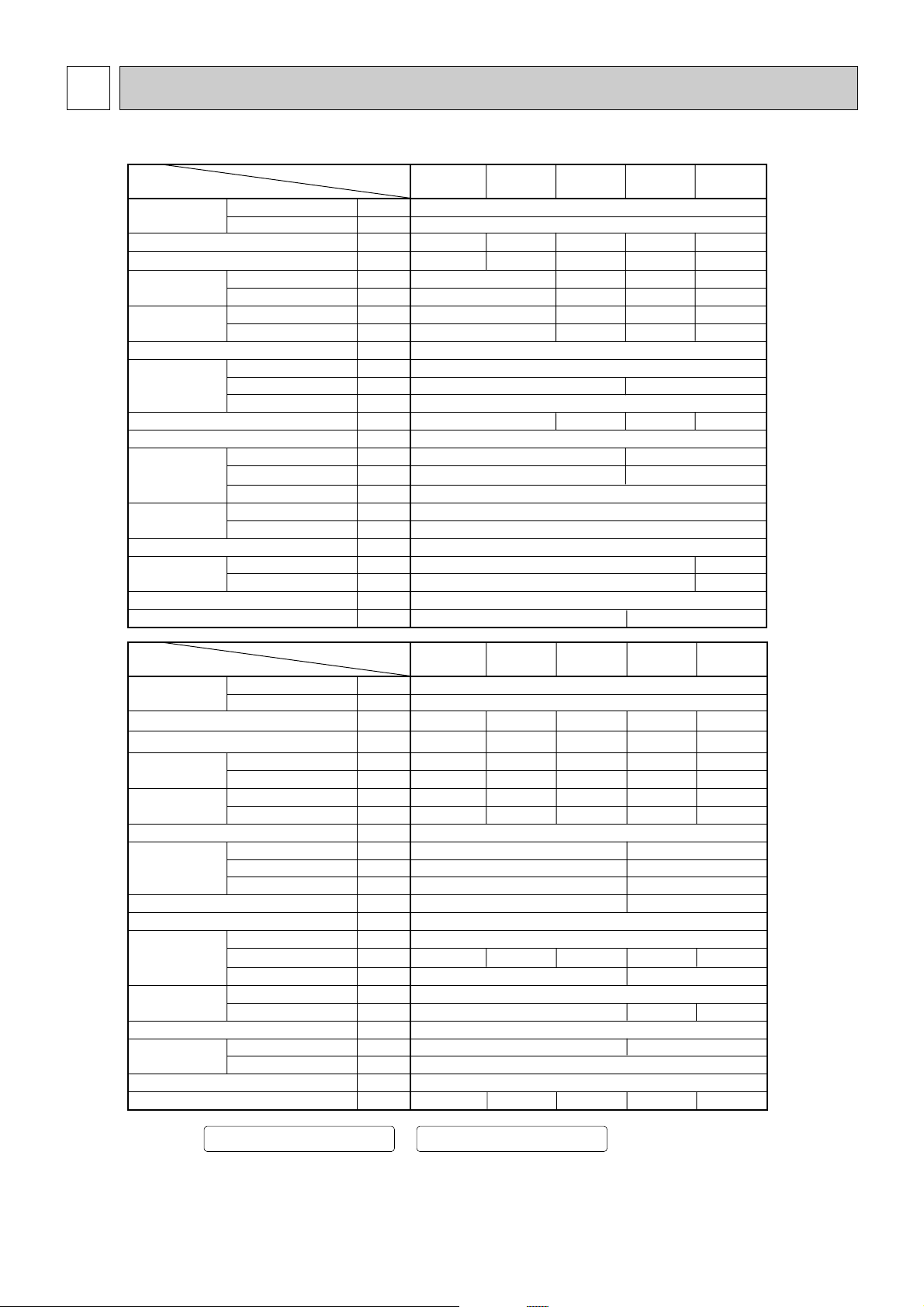
3-1. Specification
0.078
220-240 /220
50 / 60
Galvanizing
295 335
Cross fin( Alminium plate fin and copper tube)
Single phase induction motor
Synthetic fiber unwoven cloth filter( long life)
ø9.52
VP-25
Power source
Model
PDFY-P20
VM-A
PDFY-P25
VM-A
PDFY-P32
VM-A
PDFY-P40
VM-A
PDFY-P50
VM-A
Item
Dimension
Fan
Motor
Refrigerant
pipe dimension
Power cons mption
Current
Cooling capacity
Heating capacity
External finish (Munsel No.)
Net weight
Heat exchanger
Air filter
Drain pipe dimension
Noise level
(Low-Middle2-Middle1-High)
Voltage
Frequency
Cooling
Heating
Cooling
Heating
Height
Width
Depth
Type
External static pressure
Type
Output
Gas(Flare)
Liquid(Flare)
~V
Hz
kW
kW
kW
kW
A
A
mm
mm
mm
kg
m
3
/min
Pa
kW
mm
mm
dB(A)
220-240 / 220
50 / 60
3.6
4.0
0.11/0.12
0.11/0.12
0.53/0.58
0.53/0.58
Galvanizing
295
735
27
Cross fin( Alminium plate fin and copper tube)
30/50/100
Single phase induction motor
Synthetic fiber unwoven cloth filter( long life)
VP-25
4.5
5.0
5.6
6.3
2.2
2.5
2.8
3.2
0.11/0.12
0.11/0.12
0.53/0.58
0.53/0.58
710
Note:1
Note:1
Note:1
Note:1
Note:2
25.5
0.075
Sirocco fan
X
1
6.0-6.5-7.5-8.5 10.0-11.0-12.5-14.0
Sirocco fan
X
2
32 34
960
Airflow rate
u
(Low-Middle2-Middle1-High)
Power source
Model
PDFY-P63
VM-A
PDFY-P80
VM-A
PDFY-P100
VM-A
PDFY-P125
VM-A
Item
Dimension
Fan
Motor
Refrigerant
pipe dimension
Power consumption
Current
Cooling capacity
Heating capacity
External finish (Munsel No.)
Net weight
Heat exchanger
Air filter
Drain pipe dimension
Noise level
(Low-Middle2-Middle1-High)
Voltage
Frequency
Cooling
Heating
Cooling
Heating
Height
Width
Depth
Type
External static pressure
Type
Output
Gas(Flare)
Liquid(Flare)
~V
Hz
kW
kW
kW
kW
A
A
mm
mm
mm
kg
m
3
/min
Pa
kW
mm
mm
dB(A)
11.2
12.5
0.27-0.31/0.29
0.27-0.31/0.29
1.28-1.34/1.36
1.28-1.34/1.36
0.33-0.38/0.39
0.33-0.38/0.39
1.55-1.63/1.84
1.55-1.63/1.84
14.0
16.0
7.1
8.0
0.14/0.17
0.14/0.17
0.68/0.82
0.68/0.82
9.0
10.0
0.17/0.21
0.17/0.21
0.82/1.01
0.82/1.01
PDFY-P71
VM-A
8.0
9.0
0.15/0.18
0.15/0.18
0.72/0.88
0.72/0.88
1,160
39 52
0.140 0.190
Sirocco fan
X2
12.5-14.0-16.0-18.0
30/50/100 50/100/130
14.5-16.5-18.5-21.013.5-15.5-17.5-19.5
19.5-28.0 24.0-34.0
1,510
775735
Airflow rate
(Low-Middle2-Middle1-High)
ø15.88 ø19.05
30-34-36-39 32-36-38-4131-35-37-40 34(37)-42(44) 40(42)-45(46)
34-36-37-3928-30-33-36
0.13/0.15
0.13/0.15
0.60/0.71
0.60/0.71
0.13/0.15
0.13/0.15
0.60/0.71
0.60/0.71
ø 12.7
ø 6.35
ø 15.88
ø 9.52
Note: 1.Cooling / Heating capacity indicates the maximum value at operation under the following condition.
Cooling :Indoor 27°CDB/19°CWB Heating :Indoor 20°C
:Outdoor 35°CDB :Outdoor 7°CDB/6°CWB
2.Value in ( ) indicates Noise level at the 240volt/50Hz .
SPECIFICATION3
LEV
C1 3.0µF X 440V 5.0µF X 440V
5.0µF
X 440V
8.0µF
X 440V
6.0µF X 440V
MF1,2
PDFY-P20
VM-A
PDFY-P125
VM-A
PDFY-P100
VM-A
PDFY-P80
VM-A
PDFY-P71
VM-A
PDFY-P63
VM-A
PDFY-P50
VM-A
PDFY-P40
VM-A
PDFY-P32
VM-A
PDFY-P25
VM-A
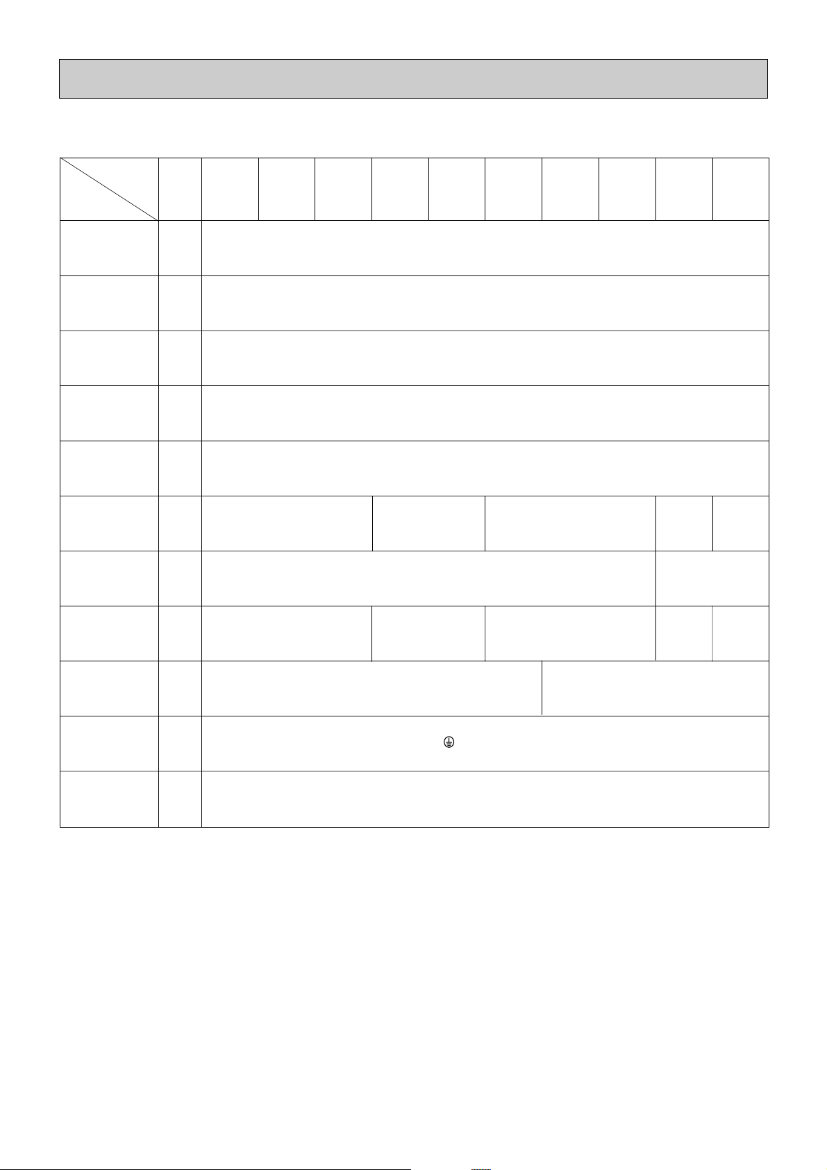
3-2. Electrical par ts specifications
Model
Parts
name
Tranrsformer T
(Primary) 240V 50Hz (Secondary) (23.5V 0.9A)
TH21 Resistance 0˚C/15kΩ,10˚C/9.6kΩ,20˚C/6.3kΩ,25˚C/5.4kΩ,30˚C/4.3kΩ,40˚C/3.0kΩ
Resistance 0˚C/15kΩ,10˚C/9.6kΩ,20˚C/6.3kΩ,25˚C/5.4kΩ,30˚C/4.3kΩ,40˚C/3.0kΩ
Resistance 0˚C/15kΩ,10˚C/9.6kΩ,20˚C/6.3kΩ,25˚C/5.4kΩ,30˚C/4.3kΩ,40˚C/3.0kΩ
TH22
Gas pipe
thermistor
FUSE
250V 6.3A
TB2
(L,N, ) 330V 30A
TB5
TB15
(1,2),(M1,M2,S) 330V 10A
Fuse
(Indoor con-
troller board)
Power supply
terminal bed
Transmission
terminal bed
OFF 130˚C±5˚C
ON 90˚C±20˚C
OFF 150˚C±5˚C
ON 96˚C±15˚C
Room
temperature
thermistor
Fan motor
(with Inner-
thermostat)
DC12V Stepping motor drive port
dimension 5.2
Ω
(0~2000pulse)
EDM-804MD
4-pole OUTPUT 75W
D104P75MW
4-pole Output 75W
D104P85MW
4-pole
4-pole
Output
Output
78W
140W
D10C4P95MW
NC-100VM1
4-pole
Output
190W
NC-125VM1
Symbol
DC12V Stepping motor drive port
dimension 3.2
Ω
(0~2000pulse)
EDM-402MD
TH23
Inner-
thermostat
(Fan motor)
Liquid pipe
thermistor
Fan motor
capacitor
Linear
expansion valve
7
8
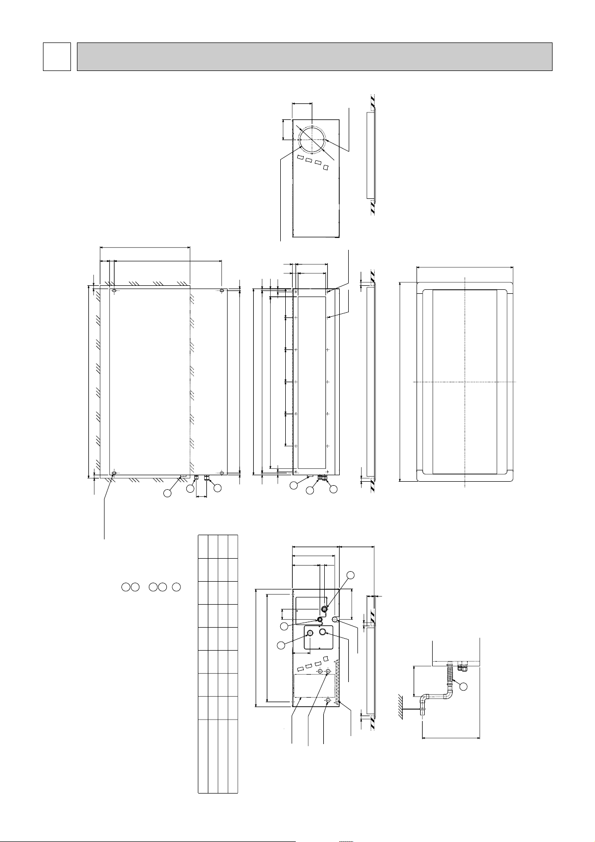
E 50
4-ø3.4 burringH-ø3 hole
H
10
8
6155
180
180
200
200
200
198 21
20
G G G G F
20
12
735
1070
168 36
PDFY-P40·50VM-A
2
1
20
20
17
17
670(Lifting bolt pitch)
670(Lifting bolt pitch) 31
When fixing the panel to indoor unit,
this dimensinon may be 50~65.
140~300
20
3
2
1
64
111
C
566(Ceiling opening)
58
20
B(Ceiling opening)
12 D(Lifting bolt pitch)
Panel (option)
870
620
1136
936
686
1160
960
710
1200
1000
750
1240
1040
790
64
Model
20~40
Gas pipe : LP ø12.7
Liquid pipe : HP ø6.35
Model
50~80
Gas pipe : LP ø15.88
Liquid pipe : HP ø9.52
···················································
················································
·················································
···············································
Drain hose VP-25 <flexible joint 200mm> (accessory) ··
Note:1. Use M10 screw for the lifting bolt (field supply).
GFEDCBAMODEL
PDFY-P63·71·80VM-A
PDFY-P20·25·32VM-A
A
600
D(Lifting bolt pitch)12 12
478
265
28
295
190
(❇2)
(❇2)
(❇1)When installing the drain water lifting-up mech(option).
(❇1)
(❇1)
(❇1)
Control box
Power source
entry
Transmission
entry
Air filter
Drain hole
Water filling port
Lifting bolt hole
4-14✕22 hole
Fresh air intake ø150 knock out hole
4-ø3 Mounting hole
300mm or less
600mmMAX
3
3
3
2
1
2
1
2
1
3
ø
172
123
126
172
Unit : mm
OUTLINES AND DIMENSIONS4
Indoor Unit
PDFY-P20·25·32·40·50·63·71·80VM-A
 Loading...