

Page 1
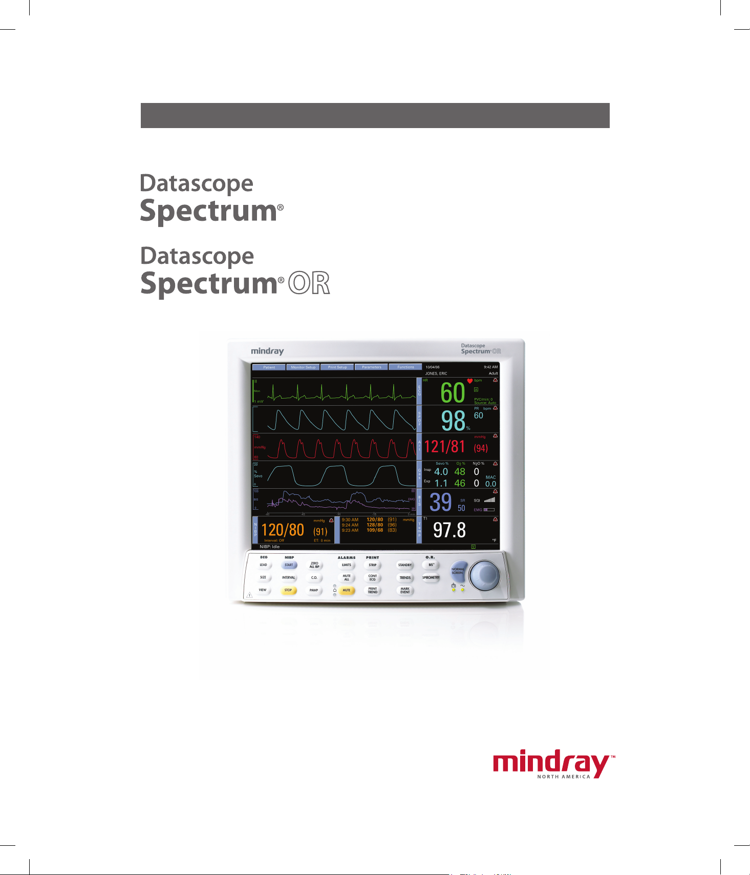
Service Manual
0070-01-0556-02_revC_srvc color.indd 1 3/15/10 10:57:25 AM
Page 2

Service Manual
Page 3

A-2000™ is a trademark of Aspect Medical
Copyright © Mindray DS USA, Inc., 2008. All rights reserved.Contents of this publication may not be reproduced in any
form without permission of Mindray DS USA, Inc.
Systems, Inc.
®
is a U.S. registered trademark of
Abbott
Abbott Laboratories.
™
is a trademark of Aspect Medical
Aspect
Systems, Inc.
™
Bispectral Index
is a trademark of Aspect
Medical Systems, Inc.
™
is a trademark of Aspect Medical
BIS
Systems, Inc.
™
is a trademark of Aspect Medical
BISx
Systems, Inc.
™
CapnoLine
is a trademark of Oridion
Medical Ltd.
®
Durasensor
is a U.S. registered trademark of
Nellcor Puritan Bennett Inc.
®
Edwards
is a U.S. registered trademark of
Edwards Lifesciences Corporation.
Navigator™ is a U.S. trademark of
Mindray DS USA, Inc.
Nellcor® is U.S. registered trademark of Nellcor
Puritan Bennett Inc.
NIV Line™ is a trademark of Oridion
Medical Ltd.
Oxiband® is a U.S. registered trademark of
Nellcor Puritan Bennett Inc.
OxiMax® is a US registered trademark of
Nellcor Puritan Bennett Inc.
Oxisensor® is a U.S. registered trademark of
Nellcor Puritan Bennett Inc.
Oxismart® is a U.S. registered trademark of
Nellcor Puritan Bennett Inc.
Panorama® is a U.S. trademark of
Mindray DS USA, Inc.
Passport 2® is a U.S. registered trademark of
Mindray DS USA, Inc.
®
FilterLine
is a U.S. registered trademark of
Oridion Medical Ltd.
®
LaserJet
is a U.S. registered trademark of
Hewlett Packard.
®
is a U.S. registered trademark of
LNOP
Masimo Corp.
®
Masimo SET
is a U.S. registered trademark
of Masimo Corp.
®
Max-Fast
is a U.S. registered trademark of
Nellcor Puritan Bennett Inc.
®
MediCO
is a registered trademark of
2
Oridion Medical Ltd.
®
miniMediCO
is a registered trademark of
2
Oridion Medical Ltd.
®
Microstream
is a U.S. registered trademark
of Oridion Medical Ltd.
PatientNet® is a U.S. registered trademark of GE
Medical Systems Information Technologies.
Spectrum® is a U.S. registered trademark of
Mindray DS USA, Inc.
Spectrum OR™ is a U.S. trademark of Mindray
DS USA, Inc.
Velcro® is a registered trademark of Velcro
Industries B.V.
View 12™ is a U.S. trademark of
Mindray DS USA, Inc.
Vigilance® is a US registered trademark of
Edwards Lifesciences Corporation.
Visa® is a U.S. registered trademark of Mindray
DS USA, Inc.
0070-10-0556-02 Spectrum®/Spectrum OR™ Service Manual
Page 4

Table of Contents
Foreword....................................................................................................................................................... v
Note .............................................................................................................................................................v
Warning........................................................................................................................................................v
Repair Information ........................................................................................................... 1 - 1
Introduction.................................................................................................................................................... 1 - 1
Safety Precautions...........................................................................................................................................1 - 1
Troubleshooting Guidelines ..............................................................................................................................1 - 2
Exchange Programs ........................................................................................................................................1 - 2
Special Tools Required ....................................................................................................................................1 - 2
Disassembly Instructions................................................................................................................................... 1 - 3
Nurse Call Cable (3 Pin Circular to Unterminated) .............................................................................................. 1 - 7
P/N 0012-00-1277-01/-02 .....................................................................................................................1 - 7
VGA Extension Cables ....................................................................................................................................1 - 8
Male 15 Pin D-Shell to Female 15 Pin D-Shell and Open Ended to Female 15 Pin D-Shell .................................1 - 8
Serial Port to Gas Module II/SE/SE with Spirometry Cable (P/N 0012-00-1276-XX) ..............................................1 - 9
Serial Port to Serial Port Cable (P/N 0012-00-1275-01) .....................................................................................1 - 10
26 pin Molex to Mini Phone Plug (DPD Sync Cable)............................................................................................1 - 11
ECG Shielded Lead Wires ...............................................................................................................................1 - 12
ECG Shielded Lead Wires ...............................................................................................................................1 - 13
Panorama Mobility Lead Wires ........................................................................................................................1 - 14
ECG Cable ESIS and Non ESIS ........................................................................................................................ 1 - 15
Panorama Mobility Cable (ESIS and Non ESIS) .................................................................................................. 1 - 16
™
View 12
12 Lead Wire Set ........................................................................................................................................... 1 - 17
Cardiac Output Cable..................................................................................................................................... 1 - 18
IABP Cable ....................................................................................................................................................1 - 19
Serial Port to RJ 45 Cable (VISA) ......................................................................................................................1 - 20
BISx Module................................................................................................................................................... 1 - 21
BISx Sensors................................................................................................................................................... 1 - 21
Beep Tones .................................................................................................................................................... 1 - 22
Troubleshooting Menus.................................................................................................................................... 1 - 23
Installation Menu ............................................................................................................................................1 - 38
Card Assembly ...............................................................................................................................1 - 17
ECG Only ..............................................................................................................................................1 - 19
ECG/IBP (only for serial numbers MSXXXXX-K5 and higher) .........................................................................1 - 19
ECG Troubleshooting ...............................................................................................................................1 - 23
NIBP Troubleshooting............................................................................................................................... 1 - 24
Troubleshooting..............................................................................................................................1 - 26
SpO
2
Temperature Troubleshooting ....................................................................................................................1 - 27
Respiration and CO
Troubleshooting........................................................................................................ 1 - 27
2
Gas Module Troubleshooting ....................................................................................................................1 - 28
IBP Troubleshooting .................................................................................................................................1 - 32
PAWP Troubleshooting............................................................................................................................. 1 - 32
EPM Cardiac Output Troubleshooting ........................................................................................................1 - 33
Vigilance Cardiac Output Troubleshooting.................................................................................................. 1 - 34
BIS Troubleshooting .................................................................................................................................1 - 34
Alarm Troubleshooting .............................................................................................................................1 - 35
Trends Troubleshooting............................................................................................................................. 1 - 36
Printer/Recorder Troubleshooting .............................................................................................................. 1 - 36
Monitor/Display Troubleshooting ..............................................................................................................1 - 37
Installation Mode.....................................................................................................................................1 - 38
Transferring Monitor Default Settings..........................................................................................................1 - 40
Option Installation ................................................................................................................................... 1 - 41
Spectrum®/Spectrum OR™ Service Manual 0070-10-0556-02 i
Page 5

Table of Contents
System Information Menu................................................................................................................................. 1 - 42
Trend Storage ................................................................................................................................................ 1 - 44
Installation and Use of the Extended Trend Feature ......................................................................................1 - 44
Software Download ........................................................................................................................................1 - 44
Download Operation ...............................................................................................................................1 - 44
Block Diagrams ................................................................................................................ 2 -1
Introduction.................................................................................................................................................... 2 - 1
Block Diagram................................................................................................................................................ 2 - 2
Isometric Drawings and Part List ....................................................................................... 3 - 1
Introduction.................................................................................................................................................... 3 - 1
Top Level Assembly .........................................................................................................................................3 - 2
Front Housing Assembly................................................................................................................................... 3 - 6
Rear Housing Assembly ...................................................................................................................................3 - 9
External Parameter Module ..............................................................................................................................3 - 26
Comm-Port ..................................................................................................................................................... 3 - 28
Calibration Procedure ....................................................................................................... 4 - 1
Introduction.................................................................................................................................................... 4 - 1
Warning and Guidelines ................................................................................................................................. 4 - 1
Test Equipment and Special Tools Required........................................................................................................ 4 - 2
Diagnostics .................................................................................................................................................... 4 - 3
Keypad / Control Knob Test ..................................................................................................................... 4 - 4
Recorder Test .......................................................................................................................................... 4 - 5
Display Tests ...........................................................................................................................................4 - 6
Pixel Test ................................................................................................................................................ 4 - 6
Color Test...............................................................................................................................................4 - 7
NIBP Tests ..............................................................................................................................................4 - 8
Error Log ................................................................................................................................................4 - 16
®
Microstream
CO2 Calibration ........................................................................................................................4 - 17
Verification ....................................................................................................................................................4 - 19
Initial Set-up............................................................................................................................................ 4 - 19
ECG Tests...............................................................................................................................................4 - 21
IBP 1, IBP 2, IBP 3 and IBP 4 (Optional) Verification ....................................................................................4 - 22
Temperature Verification........................................................................................................................... 4 - 22
Verification.................................................................................................................................... 4 - 23
SpO
2
NIBP Verification .....................................................................................................................................4 - 23
Battery Operation Verification................................................................................................................... 4 - 23
Operation Verification...................................................................................................................... 4 - 23
CO
2
Cardiac Output Verification ......................................................................................................................4 - 23
BISx Verification ......................................................................................................................................4 - 24
Leakage Current Tests ..............................................................................................................................4 - 25
Preventative Maintenance................................................................................................. 5 - 1
Preventative Maintenance Schedule .................................................................................................................. 5 - 1
Mechanical / Physical / Visual Inspection - Perform At Twelve Month Intervals................................................5 - 1
Perform Verification and NIBP Calibration – Annually ..................................................................................5 - 1
Perform Verification and CO
User Preventative Maintenance Introduction .......................................................................................................5 - 2
Care and Cleaning of the Monitor .................................................................................................................... 5 - 2
Decontamination of the Monitor........................................................................................................................5 - 2
Care and Cleaning of SpO
Cleaning and Re-use of a Nellcor
Cleaning CO
Sensors, Adapters and Sampling Components ..............................................................................5 - 3
2
Sterilization and Cleaning of Reusable Cuffs ......................................................................................................5 - 3
Calibration ..................................................................................................5 - 1
2
Sensors................................................................................................................. 5 - 2
2
®
Sensor.................................................................................................. 5 - 3
ii 0070-10-0556-02 Spectrum®/Spectrum OR™ Service Manual
Page 6

Table of Contents
Reusable Cuffs with Bladders ....................................................................................................................5 - 3
Reusable Bladderless Cuffs .......................................................................................................................5 - 4
Disposable Blood Pressure Cuffs................................................................................................................ 5 - 4
Care and Cleaning of Gas Module................................................................................................................... 5 - 4
Care and Cleaning of 3 and 5-lead ECG Cables and Leadwires ..........................................................................5 - 5
™
Care and Cleaning of View 12
ECG Analysis Module...................................................................................... 5 - 6
Battery Replacement and Maintenance ..............................................................................................................5 - 6
Battery Replacement ................................................................................................................................ 5 - 6
Battery Maintenance ................................................................................................................................5 - 6
Recorder Paper Replacement............................................................................................................................ 5 - 7
Care and Storage of Thermal Chart Paper.................................................................................................. 5 - 7
Warranty Statements....................................................................................................................................... 5 - 9
USA, Canada, Mexico, and Puerto Rico.....................................................................................................5 - 9
International (excluding North America) .....................................................................................................5 - 10
Phone Numbers and How To Get Help.............................................................................................................. 5 - 11
Manufacturer’s Responsibility ...........................................................................................................................5 - 11
Spectrum®/Spectrum OR™ Service Manual 0070-10-0556-02 iii
Page 7

Table of Contents
This page intentionally left blank.
iv 0070-10-0556-02 Spectrum®/Spectrum OR™ Service Manual
Page 8

Foreword Introduction
Foreword
The Spectrum®/Spectrum OR™ Service Manual is intended as a guide for technically
qualified personnel during repair and calibration procedures.
This publication may have been updated to reflect product design changes and/or manual
improvements.
Note
Unauthorized servicing may void the remainder of the warranty. Check with the factory or
with a local authorized representative to determine the warranty status of a particular
instrument.
Warning
The Spectrum®/Spectrum OR™ operates on line voltages. Therefore, an electric shock
hazard may exist when the instrument covers are removed. Repair and calibration
procedures should only be performed by qualified personnel who proceed with care and
follow proper servicing techniques. Warnings are given in various Chapters, as well as in
other appropriate locations.
Spectrum®/Spectrum OR™ Service Manual 0070-10-0556-02 v
Page 9

Introduction War nin g
This page intentionally left blank.
vi 0070-10-0556-02 Spectrum®/Spectrum OR™ Service Manual
Page 10

1.0
Repair Information
1.1 Introduction
This chapter of the Service Manual provides the necessary technical information to perform
repairs to the instrument. The most important prerequisites for effective troubleshooting are
through understanding of the instrument functions as well as understanding the theory of
operation.
1.2 Safety Precautions
In the event the instrument covers are removed, observe the following warnings and
guidelines.
1. Do not short component leads together.
2. The instrument covers must not be removed by other than qualified technical personnel
who have received supplementary instructions regarding maintenance of medical
equipment or has equivalent experience in this area.
Spectrum®/Spectrum OR™ Service Manual 0070-10-0556-02 1 - 1
Page 11

Troubleshooting Guidelines Repair Information
1.3 Troubleshooting Guidelines
1. Identify the problem - Due to the wide variety of potential symptoms certain
problems may be more subtle than others. One approach to troubleshooting is to set up
the instrument as described in Chapter 4.0. Following the guidelines of the tests will help
determine the problem if one exists.
2. Avoid shorting component leads - During repair procedures, it can become
tempting to make a series of quick measurements. Always turn the power off before
connecting and disconnecting the test leads and probes. The accidental shorting of
leads can easily stress the components and cause a second failure (aside from the safety
risk).
3. Use the Proper equipment - The equipment listed below is suggested to fulfill a
wide range of troubleshooting requirements. It is imperative to use the designated
equipment in order to ensure proper results of any and all test procedures.
4. Clean up the repair area - After any repair, especially after any soldering or
desoldering, clean off the repair area with alcohol and a stiff brush. This will remove
any residual solder flux, in turn allowing the instrument to return to its original
appearance.
1.4 Exchange Programs
An exchange program for certain assemblies in the instrument is available. In many cases
replacement of the complete assembly will result in the most expedient repairs.
1.5 Special Tools Required
•DVM
• Digital Mercury Manometer - 0 to 300 mmHg
• Safety Analyzer
• Patient Simulator
• Test Chamber / Dummy Cuff (P/N 0138-00-0001-01 (700 cc) or -03 (500 cc)
• BISx Sensor Simulator (P/N 0454-00-0060)
1 - 2 0070-10-0556-02 Spectrum®/Spectrum OR™ Service Manual
Page 12

Repair Information Disassembly Instructions
1.6 Disassembly Instructions
Before disassembling the unit, perform the following:
• Power down the unit and remove the line cord
• Remove all cable assemblies from the left side, right side and rear of the unit
• Remove any batteries that were installed
• Perform all work on a properly grounded ESD workstation
Removal of the Front Housing
1. Place the unit face down on a protective surface.
2. Loosen the screw from the Comm-Port or filler Port. Remove the Comm-Port or filler port
from the rear of the unit. Remove the eight screws from the rear of the unit.
3. Turn the unit over and carefully remove the front housing assembly.
4. Disconnect the 80 pin ribbon cable from the J1 of the Display / Keypad board mount in
the front housing.
Removal of the TFT Panel
1. Remove Display driver Cable assembly from J5.
2. Remove the Inverter cable assembly from J8 and the display itself.
3. Remove the encoder cable assembly from J4.
4. Remove the Speaker cable assembly from J2.
5. Remove the five screws that secure the Panel board to the front housing and place to the
side. Lift the board up and out.
6. Remove the Keypad cable assembly from J10.
7. Remove the two screws that secure the Speaker holder assembly. Remove speaker
assembly.
8. Remove the two screws that secure the High voltage inverter board to the left rail
assembly.
9. Remove the high voltage cable assembly from J2 of the inverter board. Place board
assembly to the side.
10. Turn the front assembly over and remove the encoder knob from the front.
11. Remove the nut and washer that secures the encoder to the front housing. Push the
encoder out the back of the housing and place to the side.
12. Turn the front housing back over.
13. Remove the two standoffs below the display and place to the side.
14. Remove the four screws that secure the Display assembly to the front housing brackets.
15. Slide the Display to the bottom of the front housing and lift the right side past the bracket
to remove the display.
Spectrum®/Spectrum OR™ Service Manual 0070-10-0556-02 1 - 3
Page 13

Disassembly Instructions Repair Information
Removal of the Module Interface Board
1. Remove the front housing as stated in “Removal of the Front Housing” on page 1-3.
2. Remove the four screws that secure the board to the main frame.
3. Lift board and remove.
Removal of the Main CPU board (Main Frame)
1. Remove the front housing assembly as stated in “Removal of the Front Housing” on
page 1-3.
2. Remove the NIBP Pump assembly and bracket as stated in “Removal of the NIBP Pump”
on page 1-4.
3. Remove the eight (8) screws that secures the metal shield to the back housing.
4. Remove the Power Supply assembly from the rear of the unit as stated in “Removal of the
Power Supply” on page 1-6. Once the Power Supply is removed carefully lift the Main
CPU assembly up (about one inch).
5. Disconnect the Recorder cable from J8.
6. Disconnect the connector J13 (power switch).
7. Disconnect the CO
8. Disconnect the SpO2 connector from the SpO2 board assembly (Masimo® or Nellcor®).
9. Disconnect the connector J203. (Panel board).
10. Carefully lift the CPU board assembly from the back housing.
11. Carefully angle and lift the CPU board assembly from the back housing.
12. Disconnect the connector from J202 and remove the SpO
13. Remove the ten screws that secure the CPU board to the metal frame.
connector from J 23 (CO2 module)
2
assembly.
2
Removal of the NIBP Pump
1. Remove the Front housing assembly as stated in “Removal of the Front Housing” on
page 1-3.
2. Disconnect the tubing from the inline pump filter.
3. Disconnect the connector from J8.
4. Remove Pump assembly from holding bracket.
Removal of the NIBP Module.
1. Remove the Front housing assembly as stated in “Removal of the Front Housing” on
page 1-3.
2. Remove the NIBP Pump as stated “Removal of the NIBP Pump” on page 1-4.
3. Disconnect the cable from J1.
4. Unfasten the NIBP fitting on the side of the back housing with a 3/8 inch nut driver.
5. Slide the NIBP module from the rear of the unit carefully and remove.
1 - 4 0070-10-0556-02 Spectrum®/Spectrum OR™ Service Manual
Page 14

Repair Information Disassembly Instructions
Removal of the Masimo® SpO2 Module
1. Remove the Front Housing assembly as stated “Removal of the Front Housing” on
page 1-3.
2. Remove the Main frame assembly as stated “Removal of the Main CPU board (Main
Frame)” on page 1-4.
3. Remove the three screws that secure the Masimo SpO
4. Remove the Cable assembly from J3 of the SpO
5. Lift the Masimo SpO2 Module up and remove.
module to the standoffs.
2
Module.
2
Removal of the CO2 Module
6.
Remove the front housing assembly as stated “Removal of the Front Housing” on page 1-3.
7. Remove the Main frame assembly as stated “Removal of the Main CPU board (Main
Frame)” on page 1-4.
8. Remove the Patient Connector Panel as stated in “Removal of the Patient Connector
Panel” on page 1-5.
9. Remove the four screws that secure the CO2 module to the back housing assembly.
10. Lift the Module up and out of the back housing.
Removal of the Patient Connector Panel
1. Remove the two screws that secure the Patient Connector Panel housing the back
housing.
2. Slide the Patient Connector housing toward the back.
3. Swing the housing open and remove the CO
connector retainer clip (optional).
4. Disconnect the Ribbon cable assembly from the module.
5. Remove the two screws that secure the SpO2 connector to the Panel assembly.
exhaust tubing, connector and input
2
Removal of the Recorder Assembly
1. Open the recorder door and unloosen the captive screws in the rear of the recorder.
2. Slide the recorder from the opening and remove.
Removal of Recorder Interface Board
1. Remove the Front Housing as stated in “Removal of the Front Housing” on page 1-3.
2. Remove the Main frame as stated in “Removal of the Main CPU board (Main Frame)” on
page 1-4.
3. Remove the recorder assembly as stated in “Removal of the Recorder Assembly” on
page 1-5.
4. Remove the Cable assembly from J3.
5. Remove the two screws and pull the board from the unit.
Spectrum®/Spectrum OR™ Service Manual 0070-10-0556-02 1 - 5
Page 15

Disassembly Instructions Repair Information
Removal of the Power Supply
1. Insert a narrow flat blade into each of the four slots and release each tab.
2. Ensure not to damage each tab. Remove the plastic cover.
3. Remove the four screws from the corners of the metal housing.
4. For units with Li-ion batteries only, a control cable is connected to the power
supply as shown in Figure 3-13 on page 3 - 17. The power supply cannot be completely
removed without first disconnecting this cable. Slide the power supply out of the rear of
the monitor until the control cable connector is exposed. Disconnect the control cable.
5. Slide the power supply out of the opening and remove.
Removal of the Battery Holder Assembly
1. Be sure the batteries are removed from the battery holder assembly.
2.
Remove front housing assembly as stated in “Removal of the Front Housing” on page 1-3.
3. Remove the main frame assembly as stated in “Removal of the Main CPU board (Main
Frame)” on page 1-4.
4. Remove CO2 module and CO2 mounting brackets.
5. Remove the five screws that secure the housing to the back housing.
6. Lift and remove the battery holder assembly.
Removal of the 608 MHz Radio Assembly
1. Remove the 2 screws from the radio assembly base.
2. Pull the assembly back from the monitor and place to the side.
1 - 6 0070-10-0556-02 Spectrum®/Spectrum OR™ Service Manual
Page 16
Repair Information Nurse Call Cable (3 Pin Circular to Unterminated)
NC
NO
Common
9 ft +/- 6 in.
1
2
3
1 in +/- .13 in.
6 ft +/- 1 in
E1
E2
E3
E4
E5
E6
E7
3
2
1
Connector
shield
Circuit Board
E8
BLK
RED
WHT
Cable shield
Cable
shield
BLK
RED
WHT
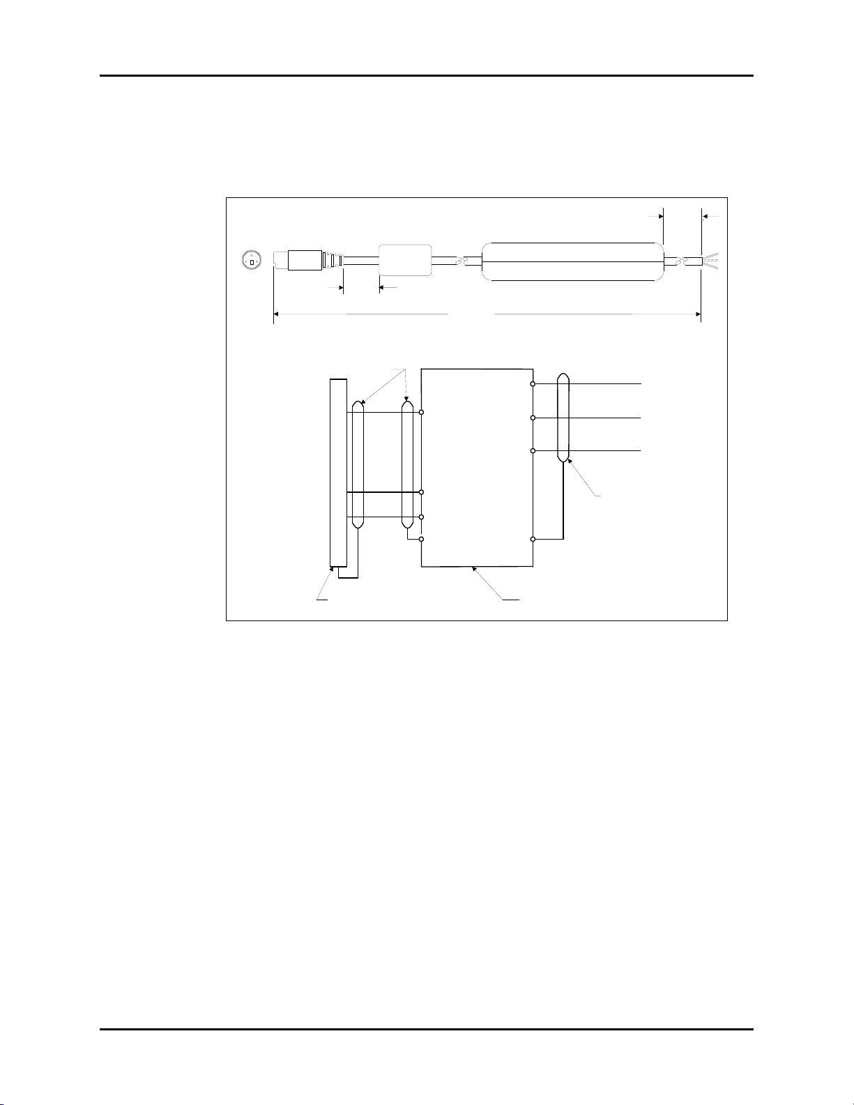
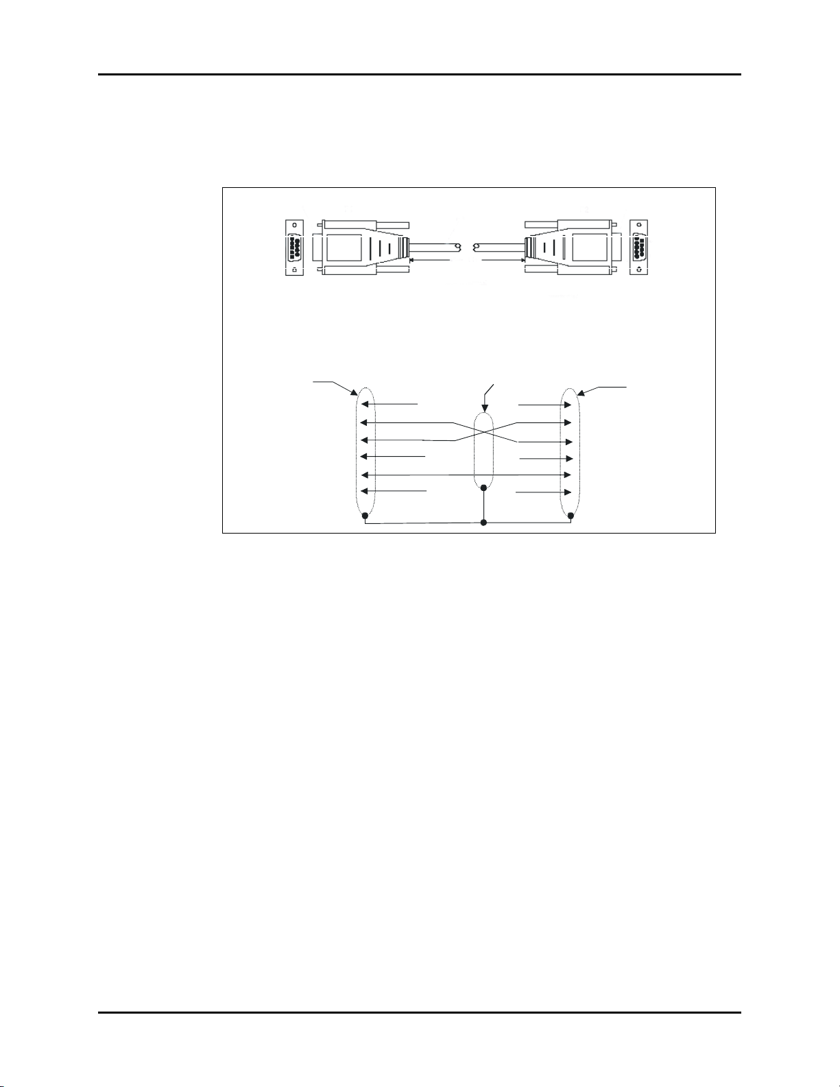
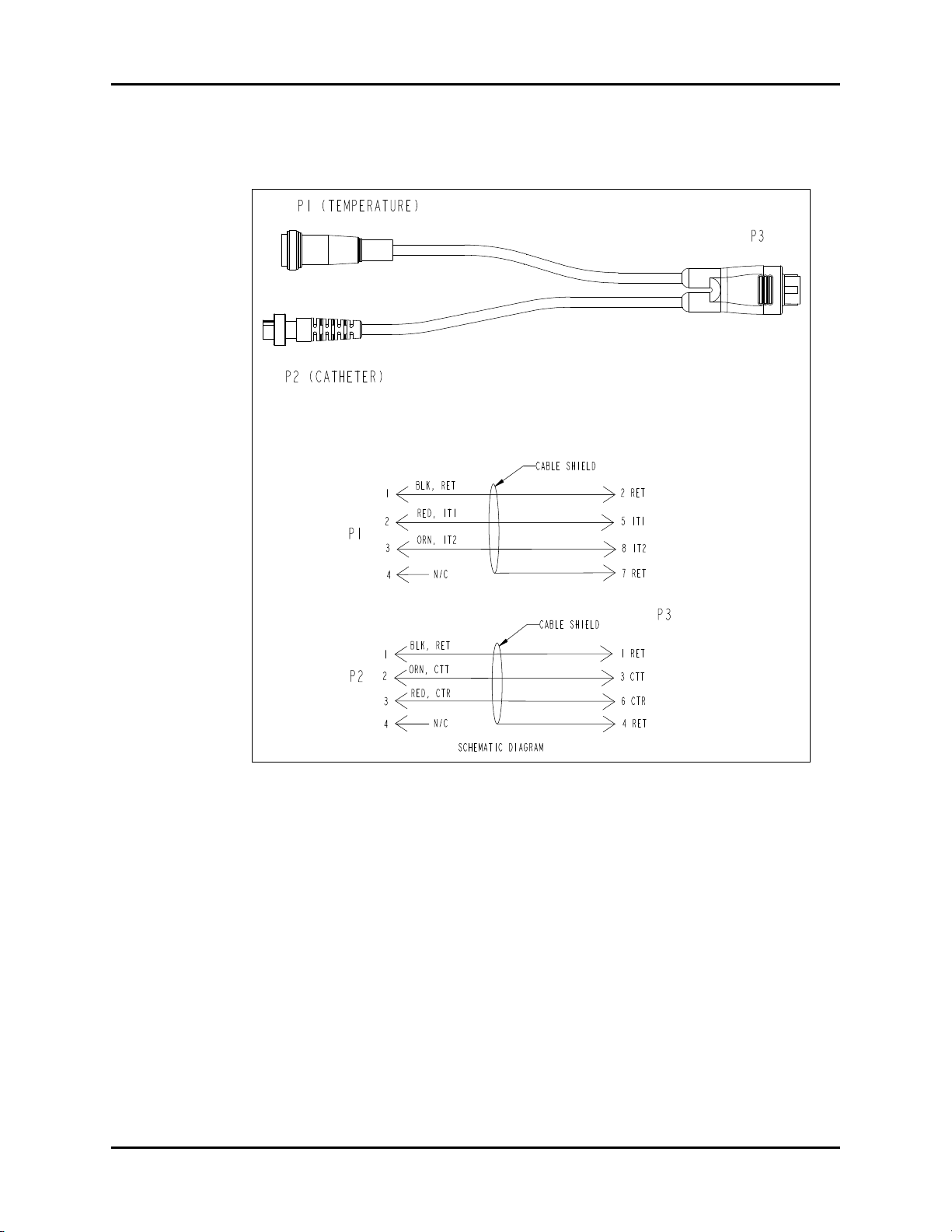
1.7 Nurse Call Cable (3 Pin Circular to Unterminated)
1.7.1 P/N 0012-00-1277-01/-02
FIGURE 1-1 Nurse Call Cable (3 Pin Circular to Unterminated)
Spectrum®/Spectrum OR™ Service Manual 0070-10-0556-02 1 - 7
Page 17
VGA Extension Cables Repair Information
Length +/- 6"
Length +/- 6"
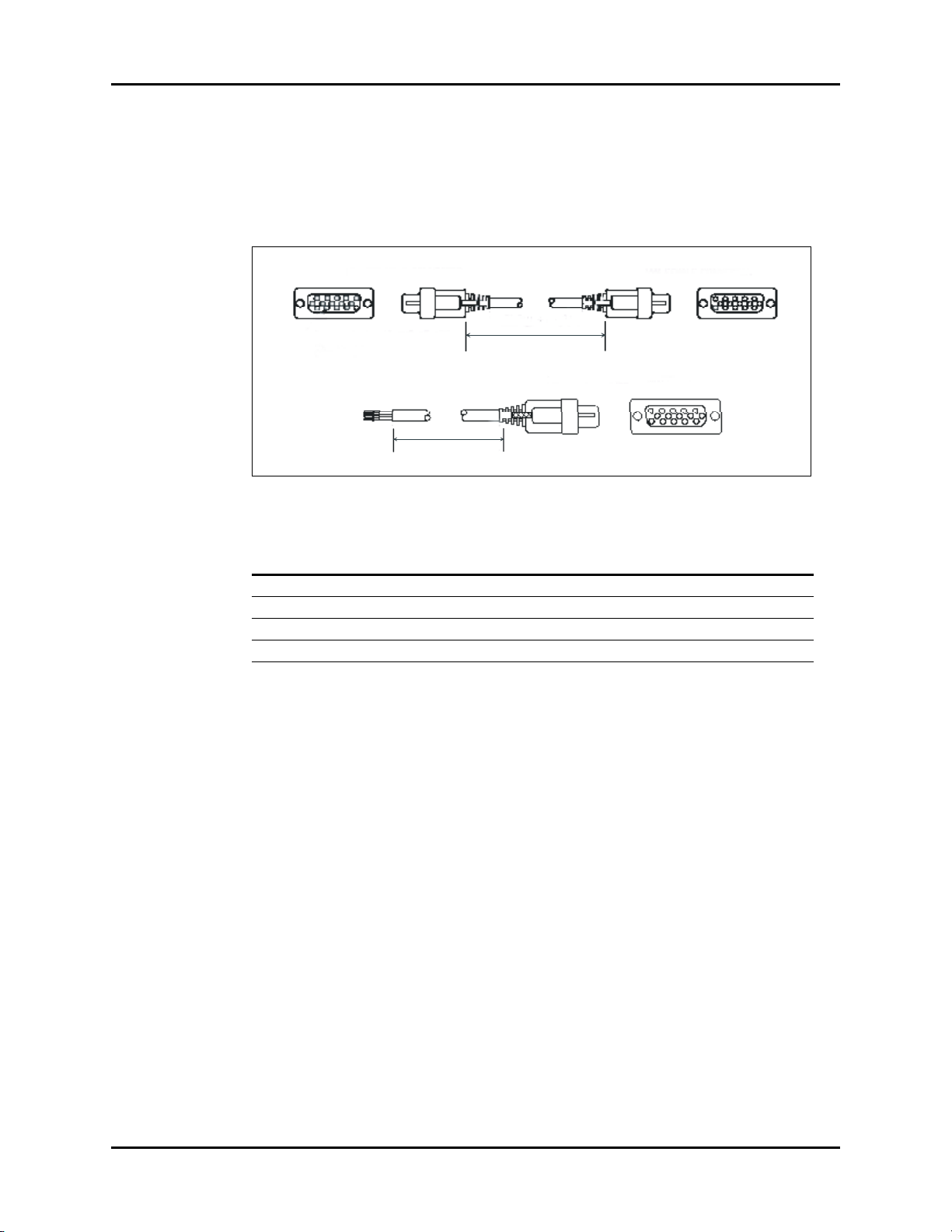
1.8 VGA Extension Cables
1.8.1 Male 15 Pin D-Shell to Female 15 Pin D-Shell and Open Ended to
Female 15 Pin D-Shell
FIGURE 1-2 VGA Extension Cables
DESCRIPTION PART NUMBER LENGTH (FT.)
Terminated 0012-00-0852-01 6
Open Ended Unterminated 0012-00-0852-02 25
Open Ended Unterminated 0012-00-0852-03 50
Open Ended Unterminated 0012-00-0852-04 100
1 - 8 0070-10-0556-02 Spectrum®/Spectrum OR™ Service Manual
Page 18
Repair Information Serial Port to Gas Module II/SE/SE with Spirometry Cable (P/N 0012-00-1276-XX)
2X +/-.131.00
L
1
5
6
9
SEE DETAIL A
DETAIL A
P1
P2
1
2
3
4
5
6-9
N.C.
N.C.
N.C.
N.C.
N.C.
N.C.
24-25
23
22
8-21
7
1-6
P2
P1
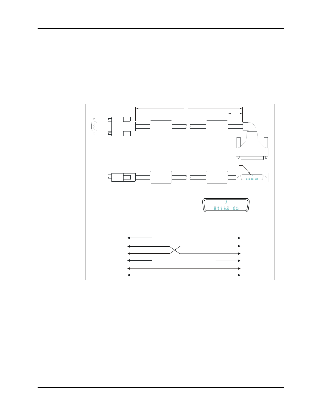
1.9 Serial Port to Gas Module II/SE/SE with Spirometry
Cable (P/N 0012-00-1276-XX)
-01 12" 9 pin mini D serial to 25 pin D shell
-02 72" 9 pin mini D serial to 25 pin D shell
FIGURE 1-3 Serial Port to Gas Module II/SE/SE with Spirometry Cable
(P/N 0012-00-1276-XX)
Spectrum®/Spectrum OR™ Service Manual 0070-10-0556-02 1 - 9
Page 19
Serial Port to Serial Port Cable (P/N 0012-00-1275-01) Repair Information
Connector Shield
Connector Shield
Cable Shield
N.C.
N.C.
N.C.
N.C.
N.C.
N.C.
1
2
3
4
5
6-9
1
2
3
4
5
6-9
P1 P2
Female
Female
P1 P2
10 ft +/-1 in.
1.10 Serial Port to Serial Port Cable
(P/N 0012-00-1275-01)
FIGURE 1-4 Serial Port to Serial Port Cable (P/N 0012-00-1275-01)
1 - 10 0070-10-0556-02 Spectrum®/Spectrum OR™ Service Manual
Page 20
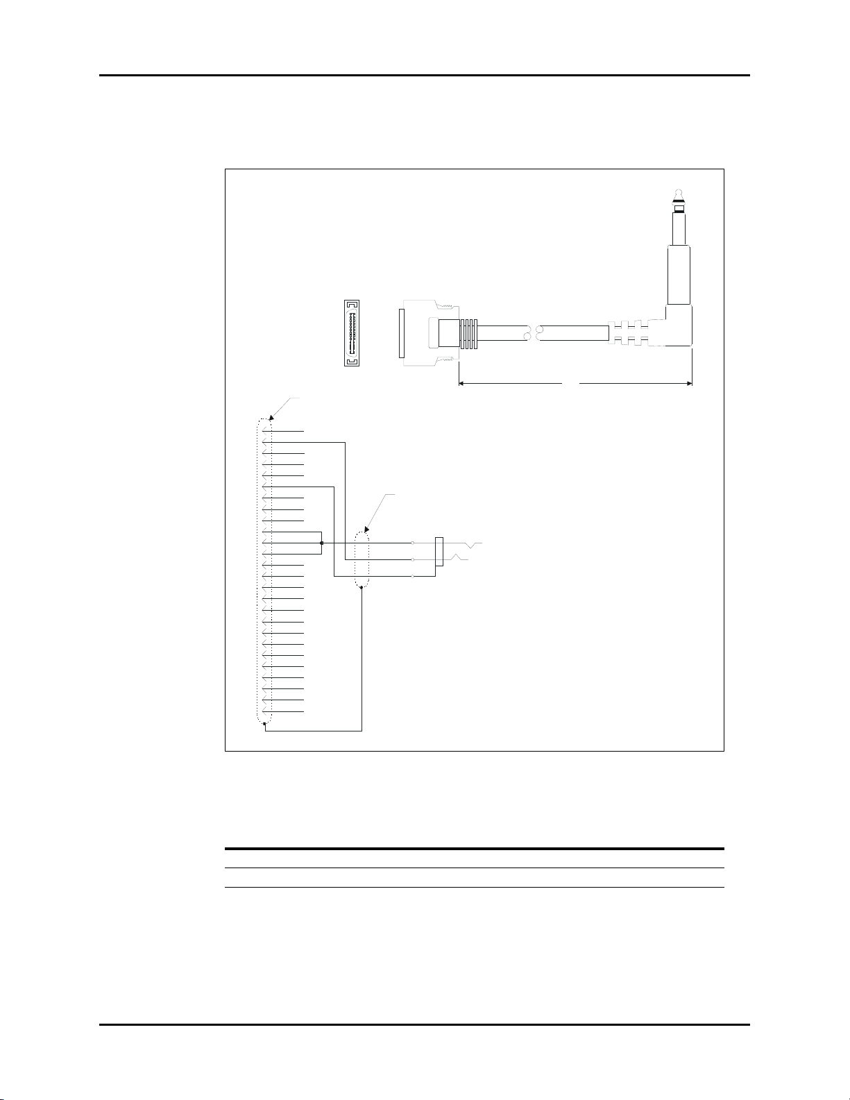
Repair Information 26 pin Molex to Mini Phone Plug (DPD Sync Cable)
P1
P2
1
26 25
2
L
P2
P1
7
6
5
4
3
2
1
8
9
10
11
12
13
14
15
16
17
18
19
20
TIP
RING
SLV
21
22
23
24
25
26
GND
RSV'd
SYNC
Connector shield
Cable shield
1.11 26 pin Molex to Mini Phone Plug (DPD Sync Cable)
FIGURE 1-5 26 pin Molex to Mini Phone Plug (DPD Sync Cable)
PART NUMBER LENGTH
Spectrum®/Spectrum OR™ Service Manual 0070-10-0556-02 1 - 11
0012-00-1301-01 8 in. +/- 1 in.
0012-00-1301-02 10 ft. +/- 6 in.
Page 21
ECG Shielded Lead Wires Repair Information
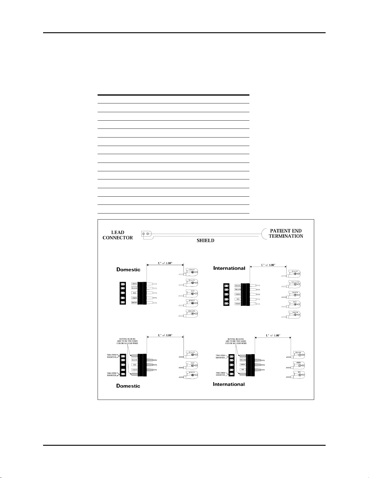
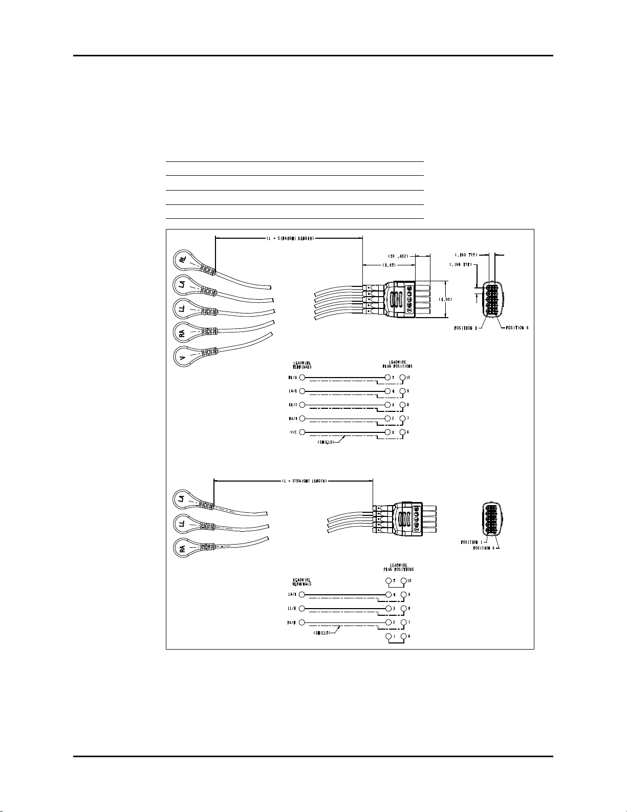
1.12 ECG Shielded Lead Wires
P/N 0012-00-1262-XX
DESCRIPTION DASH #
18" pinch 5 lead set Domestic -01
24" pinch 5 lead set Domestic -02
40" pinch 5 lead set Domestic -03
18" pinch 5 lead set International -04
24" pinch 5 lead set International -05
40" pinch 5 lead set International -06
18" pinch 3 lead set Domestic -07
24" pinch 3 lead set Domestic -08
40" pinch 3 lead set Domestic -09
18" pinch 3 lead set International -10
24" pinch 3 lead set International -11
40" pinch 3 lead set International -12
3/40", 2/60" pinch 5 lead set Domestic -13
3/40", 2/60" pinch 5 lead set International -14
FIGURE 1-6 ECG Shielded Lead Wires
1 - 12 0070-10-0556-02 Spectrum®/Spectrum OR™ Service Manual
Page 22
Repair Information ECG Shielded Lead Wires
GREEN
BLACK
RED
WHITE
BROWN
L" +/- 1.00"
GREEN
BLACK
RED
WHITE
BROWN
BLACK
YELLOW
GREEN
RED
WHITE
L" +/- 1.00"
BLACK
YELLOW
GREEN
RED
WHITE
BLACK
RED
WHITE
L" +/- 1.00"
TWO PINS
SHORTED
TWO PINS
SHORTED
KEYING BLOCKS
ARE TO BE THE SAME
COLOR AS LEAD WIRE
BLACK
RED
WHITE
YELLOW
GREEN
RED
L" +/- 1.00"
TWO PINS
SHORTED
TWO PINS
SHORTED
KEYING BLOCKS
ARE TO BE THE SAME
COLOR AS LEAD WIRE
YELLOW
GREEN
RED
LEAD
CONNECTOR
PATIENT END
TERMINATION
SHIELD
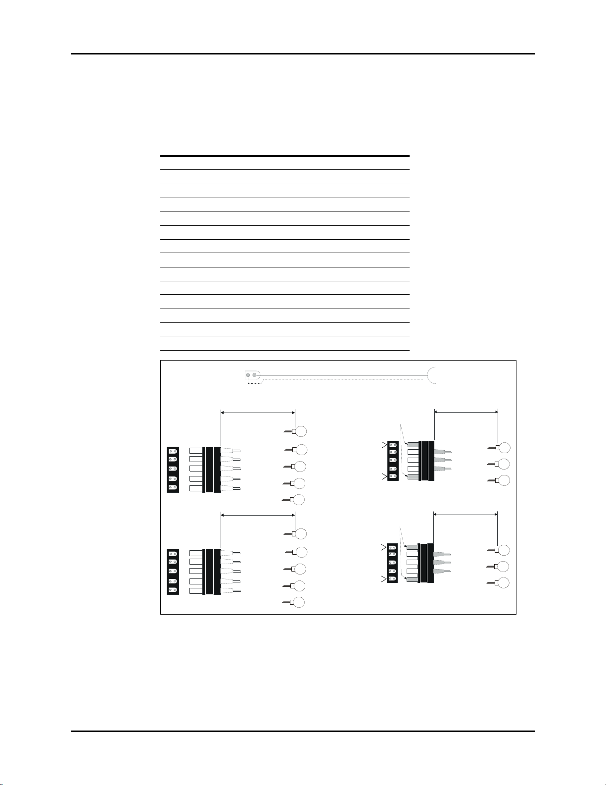
1.13 ECG Shielded Lead Wires
P/N 0012-00-1261-XX
DESCRIPTION DASH #
18" snap 5 lead set Domestic -01
24" snap 5 lead set Domestic -02
40" snap 5 lead set Domestic -03
18" snap 5 lead set International -04
24" snap 5 lead set International -05
40" snap 5 lead set International -06
18" snap 3 lead set Domestic -07
24" snap 3 lead set Domestic -08
40" snap 3 lead set Domestic -09
18" snap 3 lead set International -10
24" snap 3 lead set International -11
40" snap 3 lead set International -12
3/40", 2/60" snap 5 lead set Domestic -13
3/40", 2/60" snap 5 lead set International -14
FIGURE 1-7 ECG Shielded Lead Wires
Spectrum®/Spectrum OR™ Service Manual 0070-10-0556-02 1 - 13
Page 23
Panorama Mobility Lead Wires Repair Information
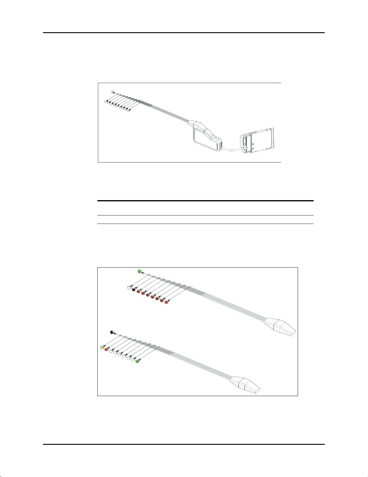
1.14 Panorama Mobility Lead Wires
P/N 0012-00-1503-XX
DESCRIPTION DASH #
24", snap, 5 lead set, Domestic -02
24", snap, 3 lead set, Domestic -05
24", snap, 5 lead set, International -11
24", snap, 3 lead set, International -14
FIGURE 1-8 Panorama Mobility Lead Wires
1 - 14 0070-10-0556-02 Spectrum®/Spectrum OR™ Service Manual
Page 24
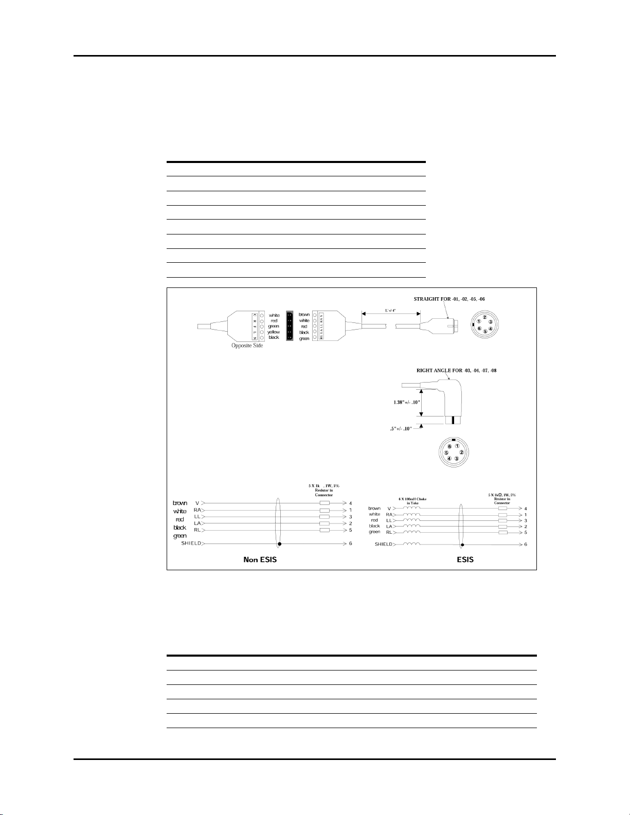
Repair Information ECG Cable ESIS and Non ESIS
1.15 ECG Cable ESIS and Non ESIS
P/N 0012-00-1255-XX
DESCRIPTION DASH #
10’ Straight Non ESIS -01
20’ Straight Non ESIS -02
10’ Rt Angle Non ESIS -03
20’ Rt Angle Non ESIS -04
10’ Straight ESIS -05
20’ Straight ESIS -06
10’ Rt Angle ESIS -07
20’ Rt Angle ESIS -08
FIGURE 1-9 ECG Cable ESIS and Non ESIS
ANSI/AAMI EC53-1995 IEC CONVENTIONAL STANDARD
LEAD COLOR LEAD COLOR
V Brown Chest (C) White
Right Arm (RA) White Right Arm (R) Red
Left Leg (LL) Red Left Leg (F) Green
Left Arm (LA) Black Left Arm (L) Yellow
Right Leg (RL) Green Right Leg (N) Black
Spectrum®/Spectrum OR™ Service Manual 0070-10-0556-02 1 - 15
Page 25
Panorama Mobility Cable (ESIS and Non ESIS) Repair Information
Non ESIS
ESIS
E (RL/N)
B (LA/L)
C (LL/F)
A (RA/R)
D (V/C)
F
E (RL/N)
B (LA/L)
C (LL/F)
A (RA/R)
D (V/C)
F
1.16 Panorama Mobility Cable (ESIS and Non ESIS)
P/N 0012-00-1502-XX
DESCRIPTION DASH #
Non ESIS, 10’, USA -01
Non ESIS, 20’, USA -02
ESIS, 10’, USA -03
ESIS, 20’, USA -04
Non ESIS, 10’, International -05
Non ESIS, 20’, International -06
ESIS, 10’, International -07
ESIS, 20’, International -08
FIGURE 1-10 Panorama Mobility Cable (ESIS and Non ESIS)
ANSI/AAMI EC53-1995 IEC CONVENTIONAL STANDARD
LEAD COLOR LEAD COLOR
V Brown Chest (C) White
Right Arm (RA) White Right Arm (R) Red
Left Leg (LL) Red Left Leg (F) Green
Left Arm (LA) Black Left Arm (L) Yellow
Right Leg (RL) Green Right Leg (N) Black
1 - 16 0070-10-0556-02 Spectrum®/Spectrum OR™ Service Manual
Page 26
Repair Information View 12™ Card Assembly
LL
V6
V5
V4
V3
V2
V1
LA
RA
RL
N
L
R
C1
C2
C3
C4
C5
C6
F
AAMI/ANSI (Domestic)
IEC (International)
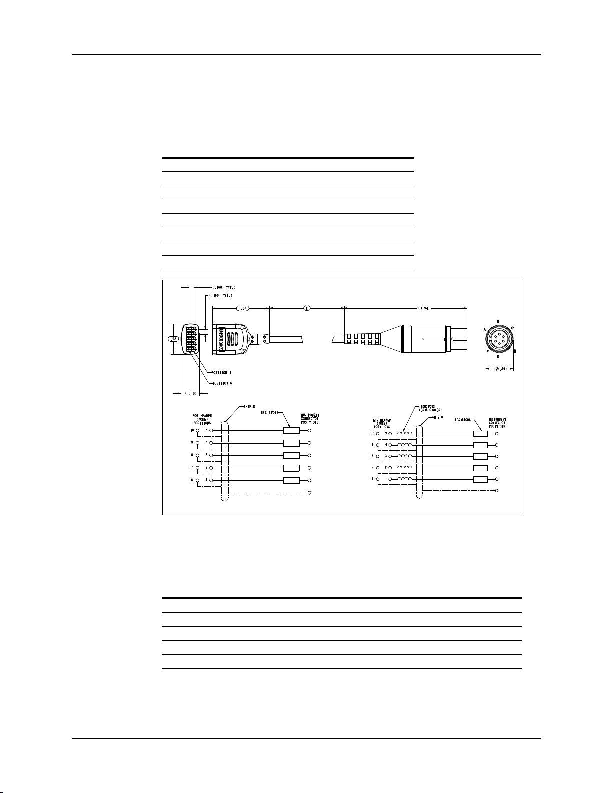
1.17 View 12™ Card Assembly
P/N 0992-00-0155-01, Spectrum® Only
FIGURE 1-11 View 12
™
Card Assembly
DESCRIPTION PART NUMBER NOTE
Cable Assembly Kit 0040-00-0324 Includes, Cable Assembly,
™
View 12
PCMCIA Card 0996-00-0065-01
1.18 12 Lead Wire Set
P/N 0012-00-1411-02 (Domestic) and P/N 0012-00-1411-03 (IEC), Spectrum® Only
(Not Included with View 12™ Card Assembly)
Cover Label
FIGURE 1-12 12 Lead Wire Set
Spectrum®/Spectrum OR™ Service Manual 0070-10-0556-02 1 - 17
Page 27
Cardiac Output Cable Repair Information
1.19 Cardiac Output Cable
FIGURE 1-13 Cardiac Output Cable (P/N 0012-00-1447-01)
1 - 18 0070-10-0556-02 Spectrum®/Spectrum OR™ Service Manual
Page 28
Repair Information IABP Cable
Connector shell
Shield drain wire
BLK
WHT
RED
AOUT1 (ECG) 1
AOUT2 (PRESS) 2
GNDA 3
AIN 4
GND 5
DOUT 6
P2, ECG
P3, PRESS
P1
TIP
SLV
RING
TIP
SLV
RING
BLK
BRN
BLK
BRN
See Note
N.C.
N.C.
N.C.
1
2
3
4
5
6
P1
2
4
1
P2
P3
3
5
5
5
1.20 IABP Cable
1.20.1 ECG Only
FIGURE 1-14 IABP Cable (ECG Only) (P/N 0012-00-1459-01)
1.20.2 ECG/IBP (only for serial numbers MSXXXXX-K5 and higher)
FIGURE 1-15 IABP Cable (ECG/IBP) (P/N 0012-00-1650-01)
Spectrum®/Spectrum OR™ Service Manual 0070-10-0556-02 1 - 19
Page 29
Serial Port to RJ 45 Cable (VISA) Repair Information
P1
1
2
3
4
5
6-9
P2
1-2
3
5
6-9
Connector shield
Cable shield
N.C.
N.C.
N.C.
N.C.
N.C.
4
1.21 Serial Port to RJ 45 Cable (VISA)
P/N 0012-00-1299-01, Spectrum® only
FIGURE 1-16 Serial Port to RJ 45 Cable (VISA)
1 - 20 0070-10-0556-02 Spectrum®/Spectrum OR™ Service Manual
Page 30
Repair Information BISx Module
Patient Interface Cable (PIC)
P/N 0012-00-1666-01
BISx Interface Cable
P/N 0012-00-1665-01
1.22 BISx Module
P/N 0992-00-0236-01, Spectrum OR™ only
FIGURE 1-17 BISx Module (Front View)
1.23 BISx Sensors
(P/N 0020-00-0491-01, -02 and -03), Spectrum OR™ only
Spectrum®/Spectrum OR™ Service Manual 0070-10-0556-02 1 - 21
FIGURE 1-18 BISx Sensors
Page 31

Beep Tones Repair Information
1.24 Beep Tones
The following tables describe the beep tones associated with the Spectrum® and
Spectrum OR
POWER ON (SPECTRUM® AND SPECTRUM OR™)
Normal Operation 1 beep
Runtime Stack Failure 2 beeps
DRAM Memory Failure 3 beeps
PCMCIA Boot Checksum Failure 4 beeps
PCMCIA Image
Checksum Failure
Flash Checksum Failure 6 beeps
Flash Programming Error 7 beeps
DRAM Checksum Error 8 beeps
ALARMS (SPECTRUM
High Priority 3 beeps/2 beeps/3 beeps/2 beeps, repeated every 10 seconds
Medium Priority 3 beeps, repeated every 30 seconds
™
monitors:
5 beeps
®
)
®
NORMAL OPERATION (SPECTRUM
Occlusion 2 beeps, repeated every 4 seconds
CO
2
NIBP Unable to Measure 1 beep
Low Battery 2 beeps, repeated every minute
ECG Noise 2 beeps, repeated every 13 seconds
™
ALARMS (SPECTRUM OR
High Priority 3 beeps/2 beeps/3 beeps/2 beeps, repeated every 10 seconds
Medium Priority 3 beeps, repeated every 10 seconds
NORMAL OPERATION (SPECTRUM OR
Occlusion 2 beeps, repeated every 4 seconds
CO
2
NIBP Unable to Measure 2 beeps with the second beep lower in pitch than the first
Low Battery 2 beeps, repeated every minute
ECG Noise 2 beeps, repeated every 13 seconds
NIBP End Tone 2 beeps with the second beep higher in pitch than the first
)
)
™
)
1 - 22 0070-10-0556-02 Spectrum®/Spectrum OR™ Service Manual
Page 32

Repair Information Troubleshooting Menus
1.25 Troubleshooting Menus
1.25.1 ECG Troubleshooting
MESSAGE/PROBLEM REASON SOLUTION
Noisy ECG traces Loose or dry electrodes. Apply fresh, moist electrodes.
Defective electrode wires. Replace wires as necessary.
Patient cable or leads are
routed too close to other
electrical devices.
Eliminate 60Hz interference.
Excessive Electro-surgical
Interference
Muscle Noise Inadequate skin preparation
Intermittent Signal Connections not tight and/or
Excessive alarms: heart rate,
lead fault
Low Amplitude ECG Signal Gain set too low. Readjust as required -
Wrong ECG cable used. Use ESIS ECG cable with
internal filter block.
NOTE: Respiration monitoring
via the ECG electrodes will not
be available when using the
cable.
Repeat skin preparation and
prior to application of
electrode, tremors, tense
subject, and/or poor electrode
placement.
properly secured.
Electrodes dry or loose. Re-prep skin and apply fresh,
Cable or lead wires damaged. Check with continuity tester.
Electrodes dry Re-prep skin and apply fresh,
Alarm limits set too close to
patient's normal heart rate.
R-wave wrong size Must have a higher amplitude
Excessive patient movement or
muscle tremor.
Electrodes dry / old Apply fresh, moist electrodes
Skin improperly prepared Abrade skin
This could be the patient’s
normal QRS complex.
Electrode could be positioned
over a bone or muscle mass.
electrode location procedures.
Apply fresh, moist electrodes.
Avoid areas of the torso that are
very muscular.
Ensure proper connection.
(Electrode to lead, lead to
cable, cable to monitor).
moist electrodes.
moist electrodes.
Readjust
than the other ECG waves, like
the P and T waves.
Reposition electrodes and
secure with tape, if necessary.
(Set via the SIZE key).
Verify with a 12-lead electro-
cardiogram.
Move ECG patches closer
towards each other.
Spectrum®/Spectrum OR™ Service Manual 0070-10-0556-02 1 - 23
Page 33

Troubleshooting Menus Repair Information
MESSAGE/PROBLEM REASON SOLUTION
No ECG Waveform Gain set too low. Readjust as required -
Lead wires and patient cable
not fully or properly inserted.
Cable or lead wires damaged. Check with lead continuity
Base Line Wander Patient moving excessively. Secure lead wires and cable to
Patient's respiration Reposition electrodes
Electrodes dry or loose Re-prep skin and apply fresh,
Static build up around patient. Check with local biomedical
ECG Filter set to “ST” or
“Extended” mode.
“Artifact” Message The 12-lead ECG is detecting
muscle artifact, or electrical
interference from auxiliary
devices.
(Set via the SIZE key).
Check for proper insertion.
tester.
patient.
moist electrodes.
personnel.
Set ECG Filter to “Monitor”
mode.
Check leads, follow skin
preparation procedure.
Check for electrical
interferences, replace wires as
necessary.
1.25.2 NIBP Troubleshooting
MESSAGE/PROBLEM REASON SOLUTION
NIBP: Idle Displayed while system is idle.
NIBP: Deflate Displayed when a measurement
NIBP: Interval Displayed during the interval
NIBP: Failure The system has detected an
NIBP: Measuring Displayed during a measurement.
NIBP: Retry Pump Higher A measurement has been
Note: This is not displayed
while in the interval mode.
that is in process is stopped by
pressing the STOP key.
between two timed measurements.
unrecoverable failure of the NIBP
system.
Cuff pressure is also displayed.
attempted but no reading was
possible. This results from
inadequate cuff inflation.
Press START to take a single
measurement. Select an
interval and start timed
measurements.
Press START to take an
immediate measurement and
resume timed measurements.
Press STOP to suspend timed
measurements.
Change timer to OFF to stop
timer.
Power cycle unit. If message
reappears, contact Customer
Support.
Press STOP to suspend a
measurement and deflate the
cuff.
Retry will be attempted.
Check that appropriate
patient size is set.
Preset initial inflation
pressure.
1 - 24 0070-10-0556-02 Spectrum®/Spectrum OR™ Service Manual
Page 34

Repair Information Troubleshooting Menus
MESSAGE/PROBLEM REASON SOLUTION
NIBP: Retry A measurement has been
Unable To Measure An unsuccessful measurement
NIBP: Cuff Overpressure The hardware overpressure limit
NIBP: Cuff Overpressure/
Press STOP to clear.
NIBP: Check Calibration The software has detected that the
Unable to obtain a BP Patient movement Wait until patient is calm or
Reading too high or too low Incorrect cuff size Measure Patient limb, use
attempted but no reading was
possible and the retry limit has not
been reached.
cycle has been completed.
has been exceeded.
The hardware overpressure limit
has been exceeded.
overpressure transducer is out of
calibration.
Cuff or hose NOT attached /
leaking
HR irregular / arrhythmia present Check Patient and notify
Blood pressure is out
of range.
Improper cuff size / brand Measure patient limb. Use
Patient movement Wait until patient is calm or
Retry will be attempted.
Check for leaks and quality of
peripheral pulses. Decrease
patient movement. Switch cuff
to another limb.
Switch cuff to another limb.
Decrease patient movement.
Press START to retry. Be
prepared to auscultate BP
manually.
Contact Customer Support.
Power cycle unit.
If message reappears, contact
Customer Support.
Press STOP to clear the
hardware overpressure.
If message reappears, contact
Customer Support.
Have the unit calibrated.
If problem persists contact
Customer Support.
gently hold limb.
Check all connections.
Physician.
Check Patient and verify BP
with manual method.
only properly sized
accessories.
correct cuff.
gently hold limb.
Spectrum®/Spectrum OR™ Service Manual 0070-10-0556-02 1 - 25
Page 35

Troubleshooting Menus Repair Information
1.25.3 SpO2 Troubleshooting
MESSAGE/PROBLEM REASON SOLUTION
SpO
: No Sensor Sensor is not plugged in to the
2
SpO
: Sensor Off
2
(Masimo SET
SpO
®
Only)
: Interference Noise detected on the pulse
2
Spectrum.
Sensor may not be connected to
the patient.
signal prevents pulse
discrimination.
SpO
: Pulse Search Hardware settings are being
2
adjusted in order to discriminate
a pulse waveform.
SpO
: No Pulse (Nellcor
2
Only)
SpO
: Failure The system has detected an
2
SpO
: Low Perfusion
2
(Masimo SET Only)
SpO
: Too Much Light
2
(Masimo SET Only)
No detectable pulse is measured Check to patient connection and
unrecoverable failure of the
SpO
system.
2
Patient perfusion is low. Check to patient connection and
There is too much ambient room
light for the sensor to function
properly
SpO
: Unrecognized
2
Sensor (Masimo SET Only)
SpO
: Communication
2
Error
The sensor is not recognized by
the Monitor.
The monitor and the SpO2
modules are not communicating
properly.
SpO
: Board Fault Masimo SET board failed to
2
operate properly.
SpO
: Sensor Fault Defective Sensor. Replace Sensor.
2
: Motion (Nellcor
SpO
2
Only)
SpO
: Check Sensor
2
(Nellcor Only)
Unable to obtain SpO
reading
Motion is detected Decrease patient motion, check
The SpO2 module has sensed a
poor connection or a bad sensor
Patient has poor perfusion. Switch limbs / Notify physician.
2
Sensor not on Patient. Reapply sensor.
Cables loose / not connected. Check connections, switch cable.
Ambient light. Switch limbs and cover sensor
No SpO
waveform Waveform not selected to
2
Display.
Cable or sensor not plugged in Check cable and sensor
Low amplitude SpO
signal
2
sensor on same limb as
SpO
2
cuff.
Patient has poor perfusion. Switch limb / Notify physician.
Plug the sensor into the monitor.
Check patient connection.
Decrease patient motion, check
sensor.
Change to site where pulse is
stronger if patient is
vasoconstricted. Change or
readjust sensor if loose.
patient status.
Power cycle unit. If message
reappears, contact Customer
Support.
patient status.
Minimize the room light around
the patient. Check sensor.
Replace the sensor with a
recommended sensor.
Power cycle unit. If problem
persists, contact Customer
Support.
See Proper Service Menu:
Suggestion.
sensor.
Reconnect the same sensor. If
problem persists, replace sensor
with opaque material.
Go to the Display Setup
Menu, choose to display Pleth
in the waveform area.
Check sensor placement, move
as necessary.
1 - 26 0070-10-0556-02 Spectrum®/Spectrum OR™ Service Manual
Page 36

Repair Information Troubleshooting Menus
1.25.4 Temperature Troubleshooting
MESSAGE/PROBLEM REASON SOLUTION
Temperature Probes not
Worki ng
Temperature not displayed Improper display setup Check display setup in Monitor
Poor contact from probes to body Check the body surface contact
at the probe tip
Reposition or apply
thermoconductive gel
Setup Menu and change as
desired
Cable not plugged in Check the cable
1.25.5 Respiration and CO
MESSAGE/PROBLEM REASON SOLUTION
Resp. Waveform Too Large Scales set inappropriately. Change lead selection.
Resp. Waveform Too Small Patient breathing is shallow or
False Apnea Alarm Apnea delay may be
No Resp. Waveform or Rate
Displayed
CO
: FilterLine® Disconnected The FilterLine is not connected
2
CO
: Warming Up The CO2 sensor has not
2
CO
: Auto-zero In Progress The CO2 sensor is. performing
2
CO
: Auto-zero Requested An Auto-zero was
2
CO
: Failure CO2 system failure. Contact Technical Support.
2
Troubleshooting
2
Change Respiration scale.
Change lead selection.
patient is turned on side.
Scale set inappropriately. Change respiration scale.
Choose an.other apnea delay
improperly set.
Patient may be having frequent
episodes of CVA.
Scale size may be too low. Change Respiration scale
Respiration turned Off. Turn respiration On (Off will be
Patient connected using ESIS
choke cable.
Cable not connected. Check cable.
to the monitor.
reached its operating
temperature.
(The monitor was just turned
on).
an auto-zero
automatically requested by the
system.
Reposition electrodes to better
detect respirations.
displayed in Resp. window).
Check that proper patient cable
is used. Use non ESIS patient
cable.
Connect the FilterLine.
Wait for the message to go
away.
It takes typically 30 seconds for
the sensor to warm up.
Wait for the auto-zero to
complete.
Wait for the auto-zero to
complete.
Spectrum®/Spectrum OR™ Service Manual 0070-10-0556-02 1 - 27
Page 37

Troubleshooting Menus Repair Information
MESSAGE/PROBLEM REASON SOLUTION
CO2: Occlusion Sampling pump line is blocked
while the CO
pump is on.
sidestream
2
Check sampling line and filter
for blockage, clear sampling
line if possible.
Replace sampling line if
necessary.
Disconnect and reconnect the
FilterLine from the Spectrum in
order to clear this message.
CO
: Purge The system has detected a
2
blocked FilterLine
®
and has
Check FilterLine and replace if
necessary.
attempted to unblock it by
temporarily increasing the flow
rate.
CO
: Check Flow Rate The system has detected a high
2
or low flow rate.
Check FilterLine and replace if
necessary.
“CHK Lead” Message Increased impedance caused
by one of the following:
Chest hair under electrodes. Prep chest.
Dried electrode gel. Change electrodes.
Electrode off. Replace electrode.
Lead off. Replace lead.
Cracked lead wires. Replace lead wires.
Poor skin prep. Clean and abrade skin before
applying electrodes.
“CVA” Message Can be caused by shallow
Check the patient.
breathing or an apnea event.
Patient HR and respiratory rate
identical.
Adjust scales or leads if
necessary.
Check the patient.
1.25.6 Gas Module Troubleshooting
MESSAGE/PROBLEM REASON SOLUTION
GM: Warming Up Appears when the system has been
turned on, and the sensors have not
reached their stable operating
temperature.
GM: Agent Warming Up This message appears after the GM:
Warming Up message disappears.
It indicates that the Agent ID Bench is
warming up and readings will not be
available.
GM: Exhaust Blocked Appears when the system detects a
blockage at the exhaust gas outlet, as
indicated by an increase in internal
pressure.
1 - 28 0070-10-0556-02 Spectrum®/Spectrum OR™ Service Manual
Wait for the message to go
away. It takes up to five
minutes for the device to
warm up.
Wait for the message to go
away. It takes up to five
minutes from power-up for the
Agent ID Bench to warm up.
Remove waste gas
scavenging assembly, check
if message disappears.
Check exhaust line for
blockage and clear if
possible. If message persists
contact Customer Support.
Page 38

Repair Information Troubleshooting Menus
MESSAGE/PROBLEM REASON SOLUTION
GM: Mixed Agents Appears when more than one
anesthetic agent is detected by the
system.
GM: Air Leak Appears when the system detects a
pneumatic leak.
Also may appear when the Gas
Module has been turned on without a
sample line attached.
Gas Module has been on for a long
period of time without the Spectrum
Monitor being on.
GM: Replace Trap Indicates residue build-up on the
Message will disappear
when a single agent is
detected again.
Turn Gas Module and
Spectrum Off.
Install/check sample lines,
filters, water trap and
electrical connections.
Turn off Gas Module.Turn on
Gas Module and Spectrum
Monitor.
Replace water trap reservoir.
water trap membrane that is
decreasing air flow.
GM: Occlusion Appears when the system detects an
obstruction in the sampling line or the
water trap bottle is full.
Empty and rinse water trap.
Change water trap if
necessary. Check sampling
line and filter for blockage,
clear sampling line if
possible. Replace sampling
line and/or filter if necessary.
If problem persists, contact
Customer Support.
GM: Zero In Progress Appears when the system is zeroing
all of it’s channels. This appears
This is normal operation.
Wait for message to clear.
whether initiated by the user or is
automatic.
GM: CO
Zero Error Appears when the system has been
2
unable to successfully zero the CO
sensor.
Manually start zeroing the
system again. If problem
2
persists, contact Customer
Support.
GM: O
Zero Error Appears when the system has been
2
unable to successfully zero the O
sensor.
Manually start zeroing the
system again. If problem
2
persists, contact Customer
Support.
GM: N
O Zero Error Appears when the system has been
2
unable to successfully zero the N
sensor.
Manually start zeroing the
system again. If problem
O
2
persists, contact Customer
Support.
GM: Agent Zero Error Appears when the system has been
unable to successfully zero the
anesthetic agent sensor.
Manually start zeroing the
system again. If problem
persists, contact Customer
Support.
GM: Pump Off Appears when the system has turned
off the pump due to a pneumatic
error.
Restart the pump from the
Gas Menu. If problem
persists, contact Customer
Support.
GM: Agent Mismatch HAL
GM: Agent Mismatch ISO
Appears when the system detects
Halothane as the primary agent and
the manually selected agent is not
Halothane.
Appears when the system detects
Isoflurane as the primary agent and
the manually selected agent is not
Isoflurane.
Match the Agent
administered with the Agent
selected, or select Agent
Auto ID.
Match the Agent
administered with the Agent
selected, or select Agent
Auto ID.
Spectrum®/Spectrum OR™ Service Manual 0070-10-0556-02 1 - 29
Page 39

Troubleshooting Menus Repair Information
MESSAGE/PROBLEM REASON SOLUTION
GM: Agent Mismatch ENF
Appears when the system detects
Enflurane as the primary agent and
the manually selected agent is not
Enflurane.
GM: Agent Mismatch SEV
Appears when the system detects
Sevoflurane as the primary agent and
the manually selected agent is not
Sevoflurane.
GM: Agent Mismatch DES
Appears when the system detects
Desflurane as the primary agent and
the manually selected agent is not
Desflurane.
GM: Unknown Agent Appears when the system detects a
Match the Agent
administered with the Agent
selected, or select Agent
Auto ID
Match the Agent
administered with the Agent
selected, or select Agent
Auto ID
Match the Agent
administered with the Agent
selected, or select Agent
Auto ID
Use recognized agent
gas that does not match the
spectroscopic signatures of the five
known anesthetic agents
GM: Cannot Zero...
RETRYING
Appears when the Spectrum
requests Zeroing (either on the
automatic cycle or by a user request)
and the Gas Module is unable to
Allow system to retry without
intervention. If problem
persist, contact Customer
Support.
initialize the cycle
GM: CO
Uncalibrated Appears after an unsuccessful
2
calibration attempt of the CO
The numeric data for CO
as - - -, and the CO
a flatline
will appear
2
waveform will be
2
sensor.
2
Ensure proper gas mixture is
attached tightly and regulator
is on. Repeat calibration
procedure. If problem
persists, contact Customer
Support.
GM: O
Uncalibrated Appears after an unsuccessful
2
calibration attempt of the O
The numeric data for O
as - - -, and the O
will appear
2
waveform will be a
2
flatline
sensor.
2
Ensure proper gas mixture is
attached tightly and regulator
is on. Repeat calibration
procedure. If problem
persists, contact Customer
Support.
GM: N
O Uncalibrated Appears after an unsuccessful
2
calibration attempt of the N
sensor. The numeric data for N
appear as - - -, and the N
waveform will be a flatline
2
O
2
O
2
O will
Ensure proper gas mixture is
attached tightly and regulator
is on. Repeat calibration
procedure. If problem
persists, contact Customer
Support.
GM: Agents Uncalibrated Appears after an unsuccessful
calibration attempt of the agent
sensor. The numeric data for all
agents will appear as - - -, and the
agent waveform will be a flatline
Ensure proper gas mixture is
attached tightly and regulator
is on. Repeat calibration
procedure. If problem
persists, contact Customer
Support.
GM: Failed Appears when the Gas Module
Contact Customer Support.
detects an unrecoverable error in its
own operation
GM: Disconnected Appears when the Spectrum cannot
detect signals being sent by the Gas
Module
Ensure Gas Module is turned
on and interface cable is
properly connected. If
problem persists, contact
Customer Support.
1 - 30 0070-10-0556-02 Spectrum®/Spectrum OR™ Service Manual
Page 40

Repair Information Troubleshooting Menus
MESSAGE/PROBLEM REASON SOLUTION
Sampling Error Appears when a sampling error
Not Ready For
Calibration
Calibration Error,
Sampling Error
Calibration Error, Zeroing
Error
occurs on one or more Gas Module
channels during calibration
Appears when the Gas Module is
unable to initialize calibration
Appears when a sampling error
occurs in all four Gas Module
channels during calibration
Appears when the Gas Module
cannot perform a Zeroing during
calibration
Repeat calibration
procedure. If problem
persists, contact Customer
Support.
Repeat calibration
procedure. If problem
persists, contact Customer
Support.
Repeat calibration
procedure. If problem
persists, contact Customer
Support.
Repeat calibration
procedure. If problem
persists, contact Customer
Support.
Spectrum®/Spectrum OR™ Service Manual 0070-10-0556-02 1 - 31
Page 41

Troubleshooting Menus Repair Information
1.25.7 IBP Troubleshooting
MESSAGE/PROBLEM REASON SOLUTION
Damped Invasive
Wav efo rm
IBP not Displayed / No
IBP Waveform
Abnormally High or Low
readings
Unable to Zero Stopcock not open to
Air bubbles in tubing. Eliminate air from tubing.
Kinked catheter. Change position of catheter,
check patient.
Catheter against wall of blood
vessel.
Blood in tubing Pump pressure bag up to 300
Catheter partially occluded with
clot.
Improper Setup. Check display setup in monitor
Cable not plugged in Check cable.
Transducer not connected. Check transducer connection.
Stopcock turned improperly. Check transducer.
Transducer not zeroed. Check and zero the transducer.
Transducer too HIGH or to LOW. Check patient adjust transducer
atmosphere.
Cable/Transducer not
plugged in.
Check for leaks at connector, flush
catheter.
mmHg.
Consult physician.
setup.
rezero.
Check transducer.
Check cable.
1.25.8 PAWP Troubleshooting
MESSAGE/PROBLEM REASON SOLUTION
Unable to Wedge Improper catheter position Check PA catheter, notify
Catheter against wall or blood
vessel
PA catheter in
Spontaneous Wedge
“Overwedging” or
dampened PAWP
Catheter in too far Notify physician immediately
Balloon overinflated Deflate balloon, reinflate slowly,
physician
Flush catheter, notify physician
notify physician
1 - 32 0070-10-0556-02 Spectrum®/Spectrum OR™ Service Manual
Page 42

Repair Information Troubleshooting Menus
1.25.9 EPM Cardiac Output Troubleshooting
MESSAGE/
PROBLEM REASON SOLUTION
CO value higher /
lower than expected
No measurement/
Unable to measure
CO Signal Under
Range
CO Out of Range Appears if the CO is out of the
Irregular curve Improper injection procedure. Check hospital policy, inject in
Delayed Injection Appears if the time between the start of
Injectate Temp Error Appears when the temperature of the
Noisy Baseline Cardiac Output waveform baseline is
Measuring Appears once an injection is detected
Injectate Temp. Out
of Range
Computation constant incorrect for PA
catheter type, injectate temperature,
and injectate volume.
Catheter may be kinked or not in proper
position.
Unstable temperature. Check injectate temperature.
No temperature or temperature out of
range.
Time elapsed for measurement. Discard bolus fluid.
Appears if the CO curve is not sufficient
for a CO calculation or if a curve is not
detected within thirty (30) seconds
measurable range
(0.2 l/min to 20.0 l/min). Computation
constant incorrect for PA catheter type,
injectate temperature, and injectate
volume.
Catheter may be kinked or not in proper
position.
Patient movement during injection. Have patient lay still during
Measurement displayed if CO curve
has multiple peaks, failure to return to
baseline or irregularities in curve.
the CO measurement and the onset of
the temperature change is more than
fifteen (15) seconds
injectate is too warm (>27ºC) or the
difference between the injectate and the
blood temperature is <8ºC.
unstable
during the process of a CO run.
Appears when the temperature of the
injectate is too warm (>27ºC) or the
difference between the injectate and the
blood temperature is <8ºC.
Check computation constant
and enter correct data.
Notify physician.
Flush PA catheter.
Check patient.
Wait f o r Ready or Inject
when Ready message to
appear. Rebolus when ready.
Rebolus if necessary
Check computation constant
and enter correct data. Rebolus
when ready.
a smooth and fluid bolus.
Notify physician.
bolus procedure.
Rebolus when ready
Rebolus when ready.
Ensure that the CO bolus is
initiated within 15 seconds
Check the temperature of the
injectate
Check injectate fluid, insure
fluid is not under warm lights,
near a warming blanket or
another warm source.
Rebolus when ready.
Check injectate fluid, insure
fluid is not under warm lights,
near a warming blanket or
over-chilled in the ice bath.
Spectrum®/Spectrum OR™ Service Manual 0070-10-0556-02 1 - 33
Page 43

Troubleshooting Menus Repair Information
MESSAGE/
PROBLEM REASON SOLUTION
Inject When Ready Appears if Auto Start is enabled,
stable temperatures are detected
Ready Appears if Auto Start is not enabled,
and stable temperatures are detected
Inject Now Appears once START has been
pressed, before bolus is initiated
Please Wait Appears after fluid bolus is initiated and
Cardiac Output is being calculated
Bolus when ready
Press START when ready
Bolus when ready
Wait until message disappears
1.25.10 Vigilance Cardiac Output Troubleshooting
MESSAGE/
PROBLEM REASON SOLUTION
CO: Check Vigilance. This message is displayed when an
alert or alarm status has been sent
from the Vigilance to the Spectrum.
Refer to the Edwards Vigilance
Monitor Operator’s Manual or
contact Edwards Lifesciences
Corporation for assistance.
®
1.25.11 BIS Troubleshooting
MESSAGE/
PROBLEM REASON SOLUTION
BIS: Check Sensor Incorrect sensor application. Read Instructions on sensor
Poor sensor connections. Check sensor connections.
Sensor Check fails. Re-prep again or replace
Defective PIC. Replace the PIC.
Defective BISx. Replace the BISx.
Problem is detected relating to sensor
ground element. Sensor Overcurrent
Sensor is using too much current.
BIS: No Sensor Disconnected sensor. Connect the sensor.
Poor or contaminated connection
between sensor and PIC.
Disconnected PIC. Connect the PIC.
Defective PIC. Replace the PIC.
Defective BISx. Replace the BISx.
BIS: Artifact Artifact, such as those generated by
motion or eye blinks, is causing loss of
EEG recognition. The BIS value and other
trend variables that are adversely
affected by artifact are not displayed.
Within the USA: (800)-424-3278
Outside the USA: (949)-250-2500
package and re-prep sensor.
sensor. Verify Sensor Check
passes.
Disconnect and examine sensor
connection. Clean any
contamination present. Replace
sensor if necessary.
Connect/clean connection
between sensor and PIC.
Attempt to identify and
eliminate artifact source.
1 - 34 0070-10-0556-02 Spectrum®/Spectrum OR™ Service Manual
Page 44

Repair Information Troubleshooting Menus
MESSAGE/
PROBLEM REASON SOLUTION
BIS: Check SQI Level EMG Bar indicates electrical activity that
may be interfering with EEG recognition.
Defective PIC. Verify Sensor Check passes. If
Defective BISx. Replace the BISx.
NOTE: This message is displayed when
the Signal Quality is less than half of the
level desirable for optimal monitoring
conditions or when the signal quality is
too low to accurately calculate a BIS
value. This may occur as the result of
artifact (non-EEG signal) such as that
generated from motion (patient
movement or eye blinks) or the presence
of electrocautery, warming blankets, or
other devices.
BIS: Invalid Sensor Poor or contaminated connection
between sensor and PIC.
Defective sensor. Replace the sensor.
Defective PIC. Replace the PIC.
Defective BISx. Replace the BISx.
BIS: Noise The signal from the electrode goes
beyond the measurable range
If EMG bar is illuminated,
attempt to determine and
eliminate cause.
not, replace PIC.
Connect/clean connection
between sensor and PIC.
Re-prep the electrodes and
check all connections.
1.25.12 Alarm Troubleshooting
MESSAGE/PROBLEM REASON SOLUTION
High or Low or No Alarm
Sound
No Arrhythmia
Alarm Sound
Alarms continue to Sound
despite pressing MUTE
No Alarm printout with
Alarm violation
Alarm limits not set Go to Alarm Setup and adjust
Alarm Mute All, On time has
not expired
Arrhythmia option not installed Call Sales Rep to purchase option
Arrhythmia Alarms off Go to Monitor Setup /
Monitor is in learning mode Wait until learning is concluded
More than one alarm is active Press MUTE or MUTE ALL key to
Print on Alarm is set to Off Go to Print Menu and set Print
alarms
Press MUTE ALL to reactivate
alarms
Advanced Setup to activate
alarm
and monitor patient closely
silence
Check Patient
on Alarm to On
Spectrum®/Spectrum OR™ Service Manual 0070-10-0556-02 1 - 35
Page 45

Troubleshooting Menus Repair Information
1.25.13 Trends Troubleshooting
MESSAGE/PROBLEM REASON SOLUTION
No Trends displayed No Trend triggers set Go to the Monitor Setup
Trend page is scrolled Use scroll button in Trend Menu
Menu and set NIBP Trend,
Trend Interval or Alarm
Trend as desired
to scroll to top of Trend Menu
1.25.14 Printer/Recorder Troubleshooting
MESSAGE/PROBLEM REASON SOLUTION
Recorder Report Appears
Totally Blank
Local Printer Door Open The printer door is not closed Close the printer door
Local Printer Out Of Paper Printer out of paper Replace with a new roll of paper
Printer Busy Printer received multiple print
Local Printer Unable To
Print
Check Laser Printer Laser printer is busy,
No print on Alarm Alarm printing not active Go to Print Setup Menu and
Trends not printing Print Trend not pressed Press PRINT TREND when trend
Thermal paper may be installed
incorrectly (up-side down)
requests at one time
The system has detected an
unrecoverable printer failure
disconnected, out of paper or has
a fault condition
No Trends displayed Use scroll feature to scroll to the
No paper Check / Replace paper
Remove paper and re-install with
paper feeding off of the spool
from the bottom
Wait until the printer is not busy
Power cycle unit. If message
reappears, contact Customer
Support.
Check laser printer
set Print on Alarm to On
window is open
top of the trend then press
PRINT TREND
1 - 36 0070-10-0556-02 Spectrum®/Spectrum OR™ Service Manual
Page 46

Repair Information Troubleshooting Menus
1.25.15 Monitor/Display Troubleshooting
MESSAGE/PROBLEM REASON SOLUTION
No trace for a desired
parameter
Trace Not Moving FREEZE key may have been
Display Appears to be Off Mains power switch may not be
Disabled Alarm Tone MUTE key pressed. Check for alarm mute symbol
Cooling Fan Failure The unit running on AC power
Patient Information did not
appear on display
Incorrect Date or Time Data not entered or entered
Improper attachment of
transducer or cable to monitor
Faulty transducer or cable. Try a new transducer or cable.
pressed.
on.
Unit may not be plugged into an
AC outlet.
If used as a portable, battery
pack may be drained.
12-lead card removed without
disabling 12-lead.
Beep volume low. Increase beep volume.
and the cooling fan is not
operational.
No data entered. Enter proper patient data.
Done was not selected from
keypad after entering data.
incorrectly.
Check transducer / cable
connection.
Press the FREEZE key to
unfreeze the trace.
Check mains power switch on
side panel.
Check power cord (Is it plugged
in?)
If battery pack is drained, plug
into an AC outlet to recharge the
battery
Always disable 12-lead card
prior to removal.
Power unit back on.
Contact Customer Support.
and message.
Contact Customer Support.
Go to the proper keypad enter
data, select Done when
finished.
Follow instructions from “How
to Set the Clock / Date and
Time”.
Spectrum®/Spectrum OR™ Service Manual 0070-10-0556-02 1 - 37
Page 47
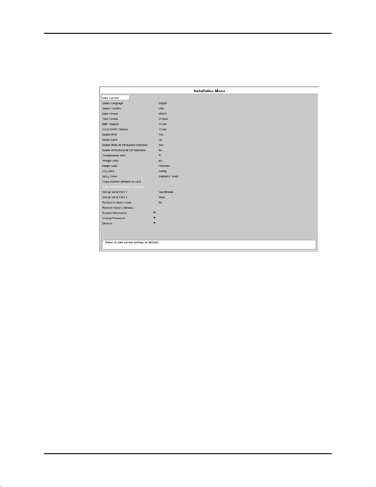
Installation Menu Repair Information
1.26 Installation Menu
1.26.1 Installation Mode
FIGURE 1-19 Installation Menu
The following items are set through the Installation Mode menu: Language, Country, Date
Format, Time Format, NIBP Timeout, CO & PAWP Timeout, Enable EPM, Apnea Latch
(Spectrum OR only), Enable Mute All Permanent Selection (Spectrum OR only), Enable
Arrhythmia All Off Selection (Spectrum OR only), Temperature Units, Weight Units, Height
Units, CO
monitor defaults from card, Set up Serial Port 1, Set up Serial Port 2, Re-boot in demo mode,
Restore factory defaults, System Information, Change Password (Spectrum OR only), and
Options.
1. Enter Installation Mode by pressing and holding the DISCHARGE key (Spectrum
2. Set each item as necessary. The operation of the menu is the same as that of the normal
Units, SpO2 Tones (Spectrum OR only), Copy monitor defaults to card, Copy
2
®
the TRENDS key (Spectrum OR
operating mode. To save all of the selected settings, choose Save Current before
exiting this menu. To access the normal operation screen, power the unit OFF and ON
again.
™
) while powering ON the monitor.
) or
1 - 38 0070-10-0556-02 Spectrum®/Spectrum OR™ Service Manual
Page 48

Repair Information Installation Menu
The following table describes the Installation Menu structure:
MENU TITLE ON
SCREEN MENU CHOICES DEFAULT
ACTIONS/
COMMENTS
Save Current Select to save current
settings as defaults
Select Language Set up at factory Select to change
language
Select Country Set up at factory Select to change
country
Date Format M/D/Y, D/Y/M Per country Select to change date
format
Time Format 12, 24 hour Per country Select to change time
format
NIBP Timeout 15, 30, 45, 60 mins 15 Selects time old and
data is removed from
screen
CO & PAWP Timeout 15, 30, 45 mins, 1, 2,
4 hr
15 min Select to change CO
and PAWP timeout.
Enable EPM Yes, No No Select to enable EPM
module
Apnea Latch On, Off On Select to turn apnea
alarm latching on or
off.
Enable Mute All
Permanent Selection
Yes, No Yes Select to enable or
disable the Permanent
Audio Off menu
selection.
Enable Arrhythmia All
Off Selection
Yes, No No Select to enable or
disable the Arrhythmia
All Off menu selection.
Temperature Units ° F, ° C ° F - USA
° C - All others
Weight Units lbs, kg lbs - USA
kg - All others
Height Units ft/ inches, cm ft/ inches - USA
cm - All others
CO
Units mmHg, %, kPa mmHg Select to change CO2
2
Select to change
temperature units
Select to ch ange weigh t
units
Select to change height
units
units
SpO
Tones Standard Tones,
2
Alternate Tones
Copy monitor defaults
to card.
Standard Tones Select to change the
SpO
tones.
2
Select to copy the
monitor defaults and
settings to a data
transfer card inserted
into PCM2
Copy monitor defaults
from card.
Select to copy the
monitor defaults and
settings from a data
transfer card inserted
into PCM2
Spectrum®/Spectrum OR™ Service Manual 0070-10-0556-02 1 - 39
Page 49

Installation Menu Repair Information
MENU TITLE ON
SCREEN MENU CHOICES DEFAULT
Set up Serial Port 1 None, VISA with
admit, DIAP, Accutorr,
Gas Module, Patient
Net (menu choices are
present only if options
are installed)
Set up Serial Port 2 None, VISA with
admit, DIAP, Accutorr,
Gas Module, Patient
Net (menu choices are
present only if options
are installed)
Re-boot in demo mode Yes, No No Set to YES to start the
Restore factory
defaults
System Information Select to set up users
Change Password Select to change
Options Select to add/view
None Select to set up a serial
None Select to set up a serial
ACTIONS/
COMMENTS
output protocol port
output protocol port
monitor in
demonstration mode on
next power-up. Normal
monitoring will resume
after cycling power in
demonstration mode.
Select to restore factory
defaults
screen
password.
options
1.26.2 Transferring Monitor Default Settings
When installing several monitors with identical display and alarm settings, a Transfer Card
(Spectrum
can be used to copy the settings from monitor to monitor.
1. Insert the Transfer Card into the PCM2 slot on the right side of the source monitor.
2. Access the Functions menu, and select Copy monitor defaults to card from the
3. Remove the card and insert it into the PCM2 slot of the receiving monitor.
4. Enter Installation Mode on the receiving monitor by pressing and holding the
5. Select Copy monitor defaults to card. A status message will report completion of
6. Select Save Current and power-cycle the receiving monitor to enter normal monitoring
®
P/N 0996-00-0094-01 only, Spectrum OR™ P/N 0996-00-0171-01 only)
menu. A status message will report completion of the transfer.
®
DISCHARGE key (Spectrum
) or the TRENDS key (Spectrum OR™) while
powering ON the monitor.
the transfer.
mode.
1 - 40 0070-10-0556-02 Spectrum®/Spectrum OR™ Service Manual
Page 50

Repair Information Installation Menu
1.26.3 Option Installation
1. Install option PCMCIA card (P/N 0996-00-0053-XXXXX) into slot PCM2.
2. Select “Install” from the menu selection. Press the Navigator™ knob to activate new
option.
3. Verify proper operation as stated in chapter 4.0.
Spectrum®/Spectrum OR™ Service Manual 0070-10-0556-02 1 - 41
Page 51

System Information Menu Repair Information
1.27 System Information Menu
FIGURE 1-20 System Information Menu
This menu is accessed by selecting System Information from the Installation Menu.
Information is entered via a on-screen keyboard. Select each letter using the Navigator
™
Knob. When finished, rotate to Previous Menu and select using the Navigator Knob.
MENU TITLE ON
SCREEN
Previous Menu Select to return to Previous Menu
Property Of Select to set up Property of name
Location Select to set up Location
Department Select to set up Department
Contact Select to set up Contact
Phone Select to set up Phone
Accutor Baud Rate
(Spectrum only)
DIAP Baud Rate 9600, 19200 Select to change the DIAP baud rate
Enable Network Not Used
IP Address: Select to set up IP Address
Subnet Mask ID: Select to set up Subnet Mask ID
Wireless IP Address
(Spectrum only)
MENU
CHOICES DEFAULT TEXT STRINGS
9600, 1200 Select to change the Accutorr
protocol baud rate
Select to set up Wireless IP Address
1 - 42 0070-10-0556-02 Spectrum®/Spectrum OR™ Service Manual
Page 52

Repair Information System Information Menu
MENU TITLE ON
SCREEN
Wireless Subnet Mask ID
(Spectrum only)
Laser Printer IP Address
(Spectrum only)
Network Name: Select to set up Network name
Device ID
MENU
CHOICES DEFAULT TEXT STRINGS
Select to set up Wireless Subnet
Mask ID
Spectrum®/Spectrum OR™ Service Manual 0070-10-0556-02 1 - 43
Page 53

Trend Storage Repair Information
1.28 Trend Storage
1.28.1 Installation and Use of the Extended Trend Feature
The Spectrum®/Spectrum OR™ monitor is capable of storing, in non-volatile memory, up
to 120 trend values for each parameter, and for Spectrum
CRG data. With the addition of the Extended Trend card (P/N 0996-00-0052-01), the
Spectrum
parameter, and for Spectrum
This feature is added to the Spectrum
card (P/N 0996-00-0052-01) into slot PCM1 on the right side of the monitor. The card
should be inserted before monitor power-up, and never removed during monitor operation.
In order to guard against accidental removal, the card slot is designed so that a tool is
required to eject the card after insertion.
The Extended Trend feature is automatically enabled when the unit is powered-up following
card insertion.
®
/Spectrum OR™ is capable of storing up to 500 trend values for each
®
only, up to 12 hours of OXY-CRG data.
®
/Spectrum OR™ by inserting the Extended Trend
®
only, up to 6 minutes of OXY-
NOTE: All prior trended information is lost upon installation of the
Extended Trend feature.
1.29 Software Download
1.29.1 Download Operation
A download flashcard must be installed in PCMCIA slot PCM2 prior to power up. When the
unit is powered on, the valid download card will be read and downloaded to the Host CPU
module only. While the images are being downloaded a beep will sound approximately
once every second until the download is complete. Once complete, the unit will then run
automatically, first displaying the Spectrum
normal runtime mode. A display box will be displayed if it is determined that the images
downloaded to the Host CPU module do not match the images in the attached CP and/or
Front-end modules and/or EPM modules. This display box, shown below, will indicate the
Host CPU software version, the current version on the CP, Front-end and/or EPM modules
and the software version being downloaded to the modules. The images will automatically
load and the status message Complete will appear, after the download is complete.
NOTE: To ensure that the EPM module download is complete,
reboot the unit.
Module Module SW
Ver s i o n
The above modules are being downloaded. When the download is complete, press the
normal screen button to continue, or reboot.
®
/Spectrum OR™ logo then proceeding to
Flash SW Version Status Download
Percent
FIGURE 1-21 Software Download Status Screen
1 - 44 0070-10-0556-02 Spectrum®/Spectrum OR™ Service Manual
Page 54

Repair Information Software Download
Status Messages
Pending: This is displayed for a module awaiting download.
Active: This is displayed once a pending module has turned active.
Erasing: This is displayed when an image is being erased.
Loading: This is displayed when an image is being downloaded.
Verify: This is displayed while the checksum is being verified.
Fault: This is displayed if there is a downloading error. If a fault occurs, the module
download screen will not be able to be removed. Contact customer service.
Complete: This is displayed for a module when download is complete.
NOTE: If a fault condition occurs, an error message will be
recorded in the error log.
Spectrum®/Spectrum OR™ Service Manual 0070-10-0556-02 1 - 45
Page 55

Software Download Repair Information
This page intentionally left blank.
1 - 46 0070-10-0556-02 Spectrum®/Spectrum OR™ Service Manual
Page 56

2.0
Block Diagrams
2.1 Introduction
The Block Diagrams indicate the internal organization of the instrument. The block diagrams
are used to gain both familiarity with the instrument and to locate malfunctioning PC boards
as readily as possible.
Spectrum®/Spectrum OR™ Service Manual 0070-10-0556-02 2 - 1
Page 57

Block Diagram Block Diagrams
P1
SW1
SW3 SW6
SW7
SW10 SW13
SW16
SW17
SW14SW11SW8
SW19SW4
SW2
SW15
SW12
SW9
SW20
SW5
SW21
SW18
CPU Board Assembly
P/N 0670-00-0739-02
or 0670-00-0782-03
Speaker
AC Input
J10
J4
J2
J1
Equipotential
Lug
J5
+ -
ECG
NIBP
IBP
ALARMS PRINT DISPLAY
Lead
Size
View
Stop
Interval
Start
Zero
All
Limits
Mute
All
Mute
Print
Trend
Cont
ECG
Strip
Standby
Discharge
Mark
Event
Trends
Freeze
Normal
Screen
J4
J13
J24
J22
J21
J5
J9
J6
J200
J202
J23
J12
Recorder
Recorder
Interface Bd.
Fan
Power
Switch
Power Supply
Line Cord
Ballon
Pump
Interface
DPD Defib
Interface
Batteries
Keypad Overlay and
Keypad Switch Assembly
Keypad / Panel
Interface Bd.
LCD Display
Comm Port
NIBP Module
Patient Connector Bd.
Spo2 Module
(Masimo)
Spo2 Interface Bd.
(Nellcor)
Co2 Module
External Module
External Module
Interface Bd.
Spo2 Module
(Nellcor)
See Next Page
for Details
J8
J15
608MHz Radio Assembly
Spo2 Interface Bd.
(Masimo- Use with
0782-03 CPU)
CPU Board Assembly
P/N 0670-00-0782-02
or 0670-00-0782-01
2.2 Block Diagram
FIGURE 2-1 Spectrum® Block Diagram
DESCRIPTION PART NUMBER DESCRIPTION PART NUMBER
Recorder Assembly 0683-00-0465-01 NIBP Board 0670-00-0798-01
Recorder Board 0670-00-0695 Patient Connector Board 0670-00-0682-01
Fan 0012-00-1622-01 Patient Connector Board (HP) 0670-00-0680-01
Power Switch 0012-00-1231 SpO
Power Supply 0014-00-0250 or
Batteries 0146-00-0043 or
Panel / Keypad Board 0670-00-0735 SpO
LCD Display 0160-00-0094 SpO
Keypad Overlay 0330-00-0037-XX Oridion MediCO
Keypad 0331-00-0120-XX Power Cord (Domestic) 0012-25-0001
Speaker 0012-00-0257-06 Power Cord (International) 0012-25-0002
608 Radio Kit 0040-00-0361-01 External Module Interface Board 0670-00-1155-01
NIBP Board 0670-00-0746-01
NOTE: See Isometric Drawings and Parts List for a complete list of Part Numbers.
2 - 2 0070-10-0556-02 Spectrum®/Spectrum OR™ Service Manual
0014-00-0251
0146-00-0069
Module (Masimo) 0671-00-0055
2
Module (Nellcor) Oximax 0671-00-0066
SpO
2
SpO
Module (Nellcor) 0671-00-0162
2
Interface Board (Nellcor) 0670-00-0696 or
2
Interface Board (Masimo) 0670-00-0785-03
2
Module
Oridion miniMediCO
2
Module
2
0670-00-0785-01, 02
0671-00-0164-03
0671-00-0089-01
Page 58

Block Diagrams Block Diagram
P1
SW1
SW3 SW6
SW7
SW10 SW13
SW16
SW17
SW14SW11SW8
SW19SW4
SW2
SW15
SW12
SW9
SW20
SW5
SW21
SW18
CPU Board Assembly
0670-00-0782-03
Speaker
AC Input
J10
J4
J2
J1
Equipotential
Lug
J5
+ -
ECG
NIBP
IBP
ALARMS PRINT OR
Lead
Size
View
Stop
Interval
Start
Zero
All
Limits
Mute
All
Mute
Print
Trend
Cont
ECG
Strip
Standby
Trends
Mark
Event
BIS
Spirometry
Normal
Screen
J4
J13
J24
J22
J21
J5
J9
J6
J200
J202
J23
J12
Recorder
Recorder
Interface Bd.
Fan
Power
Switch
Power Supply
Line Cord
Ballon
Pump
Interface
DPD Defib
Interface
Batteries
Keypad Overlay,
Keypad Switch Assembly
Keypad / Panel
Interface Bd.
LCD Display
Comm Port
NIBP Module
Patient Connector Bd.
Spo2 Module
(Masimo)
Co2 Module
External Module
External Module
Interface Bd.
Spo2 Module
(Nellcor)
See Next Page
for Details
J8
J15
Spo2 Interface Bd.
(Nellcor) & (Masimo)
B
I
S
X
BisX Module
BISX Sensors
CPU Board Assembly
0670-00-0782-01
Spectrum®/Spectrum OR™ Service Manual 0070-10-0556-02 2 - 3
FIGURE 2-2 Spectrum OR™ Block Diagram
DESCRIPTION PART NUMBER DESCRIPTION PART NUMBER
Recorder Assembly 0683-00-0465-01 NIBP Board 0670-00-0746-01
Recorder Board 0670-00-0695 NIBP Board 0670-00-0798-01
Fan 0012-00-1622-01 Patient Connector Board 0670-00-0682-01
Power Switch 0012-00-1231 SpO
Power Supply 0014-00-0250 or
Batteries 0146-00-0043 or
Panel / Keypad Board 0670-00-0735 SpO
LCD Display 0160-00-0094 Oridion MediCO
Keypad Overlay 0330-00-0037-XX Power Cord (Domestic) 0012-25-0001
Keypad 0331-00-0120-XX Power Cord (International) 0012-25-0002
Speaker 0012-00-0257-06 External Module Interface Board 0670-00-1155-01
NOTE: See Isometric Drawings and Parts List for a complete list of Part Numbers.
0014-00-0251
0146-00-0069
Module (Masimo) 0671-00-0055
2
Module (Nellcor) Oximax 0671-00-0066
SpO
2
SpO
Interface Board (Nellcor) 0670-00-0785-01
2
Interface Board (Masimo) 0670-00-0785-03
2
Module
Oridion miniMediCO
2
Module
2
0671-00-0164-03
0671-00-0089-01
Page 59

Block Diagram Block Diagrams
External Module Main Board
(P/N 0670-00-0734-01)
J8
J7
J9
J4
External Device
External Module
Interface Board
Patient Connector Board
Keypad
Spectrum CPU Board
IBP
CO
Keypad Overlay
See Previous Page
Tem p
IBP 3
IBP 4
FIGURE 2-3 Block Diagram (External Parameter Module Main Board)
DESCRIPTION PART NUMBER
External Parameter Module Main Board 0670-00-0734-01
Connector Panel Board 0670-00-0738-01
Keypad 0331-00-0118
Keypad Overlay IBP 3/4, T2 0330-00-0038-XX
Interface Board 0670-00-1155-01
NOTE: See “Isometric Drawings and Part List” on page 3-1 for a
complete list of Part Numbers.
2 - 4 0070-10-0556-02 Spectrum®/Spectrum OR™ Service Manual
Page 60

3.0
Isometric Drawings and Part List
3.1 Introduction
This chapter provides information necessary to identify the replacement parts and assemblies
of instruments.
Spectrum®/Spectrum OR™ Service Manual 0070-10-0556-02 3 - 1
Page 61
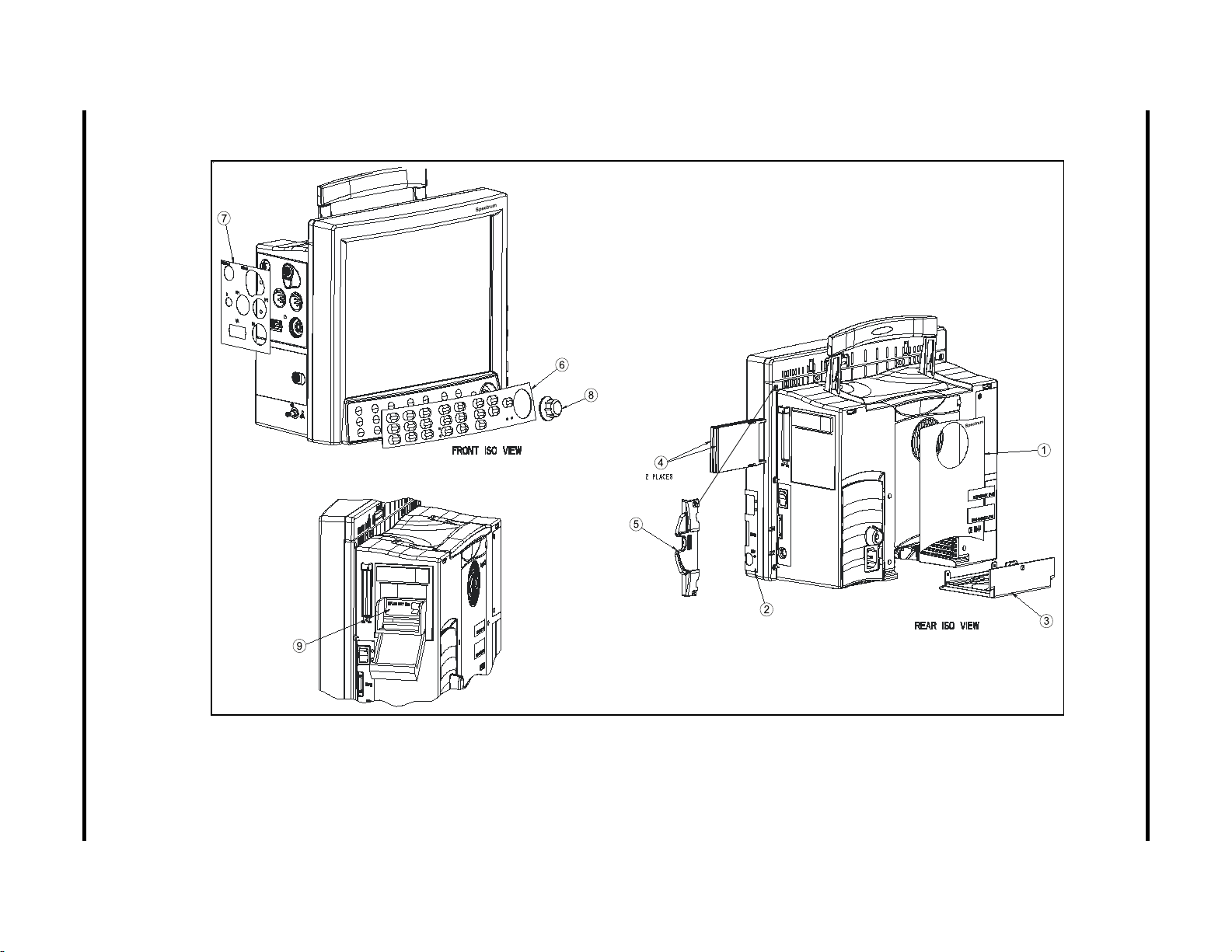
3 - 2 0070-10-0556-02 Spectrum
3.2 Top Level Assembly
Top Level Assembly Isometric Drawings and Part List
®
/Spectrum OR
™
Service Manual
FIGURE 3-1 Top Level Assembly
Page 62

Isometric Drawings and Part List Top Level Assembly
ITEM
NO DESCRIPTION PART NUMBER
1 Label, Rear Information, Spectrum
®
1 Label, Rear Information, Spectrum OR
™
0334-00-2623
0334-00-1724
2 Label, Right Side 0334-00-1528
3 Cover Assembly, Docking Connector 0198-00-0037
4 PCMCIA Card Dummy 0380-00-0372
™
5 Bracket, View 12
6 Keypad Overlay, English, Spectrum
6 Keypad Overlay, German, Spectrum
6 Keypad Overlay, French, Spectrum
6 Keypad Overlay, Spanish, Spectrum
6 Keypad Overlay, Italian, Spectrum
6 Keypad Overlay, Dutch, Spectrum
6 Keypad Overlay, Br. Portuguese, Spectrum
6 Keypad Overlay, English, Spectrum OR
7 Label, Patient Connector w/CO
7 Label, Patient Connector w/CO
7 Label, Patient Connector no CO
PCMCIA (Optional) 0380-00-0399-01
®
®
®
®
®
®
®
™
w/IBP Nellcor®, English 0334-00-1501-001
2
w/IBP Masimo®, English 0334-00-1501-002
2
w/IBP Nellcor, English, Italian,
2
0330-00-0037-01
0330-00-0037-02
0330-00-0037-03
0330-00-0037-04
0330-00-0037-05
0330-00-0037-06
0330-00-0037-08
0330-00-0058-01
0334-00-1501-003
Br. Portuguese
7 Label, Patient Connector no CO
w/IBP Masimo, English, Italian,
2
0334-00-1501-004
Br. Portuguese
7 Label, Patient Connector w/CO
7 Label, Patient Connector w/CO
7 Label, Patient Connector no CO
Spanish, Italian, Dutch, Br. Portuguese
7 Label, Patient Connector no CO
Spanish, Italian, Dutch, Br. Portuguese
7 Label, Patient Connector w/CO
7 Label, Patient Connector w/CO
7 Label, Patient Connector no CO
7 Label, Patient Connector no CO
7 Label, Patient Connector w/CO
7 Label, Patient Connector w/CO
7 Label, Patient Connector no CO
7 Label, Patient Connector no CO
7 Label, Patient Connector w/CO
7 Label, Patient Connector w/CO
7 Label, Patient Connector no CO
7 Label, Patient Connector no CO
7 Label, Patient Connector w/CO
7 Label, Patient Connector w/CO
7 Label, Patient Connector w/CO
7 Label, Patient Connector w/CO
7 Label, Patient Connector w/CO
7 Label, Patient Connector w/CO
no IBP Nellcor, English 0334-00-1501-005
2
no IBP Masimo, English 0334-00-1501-006
2
no IBP Nellcor, English, French,
2
no IBP Masimo, English, French,
2
w/IBP Nellcor, German 0334-00-1501-011
2
w/IBP Masimo, German 0334-00-1501-012
2
w/IBP Nellcor, German 0334-00-1501-013
2
w/IBP Masimo, German 0334-00-1501-014
2
no IBP Nellcor, German 0334-00-1501-015
2
no IBP Masimo, German 0334-00-1501-016
2
no IBP Nellcor, German 0334-00-1501-017
2
no IBP Masimo, German 0334-00-1501-018
2
w/IBP Nellcor, French 0334-00-1501-021
2
w/IBP Masimo, French 0334-00-1501-022
2
w/IBP Nellcor, French, Spanish 0334-00-1501-023
2
w/IBP Masimo, French, Spanish 0334-00-1501-024
2
no IBP Nellcor, French 0334-00-1501-025
2
no IBP Masimo, French 0334-00-1501-026
2
w/IBP Nellcor, Spanish 0334-00-1501-031
2
w/IBP Masimo, Spanish 0334-00-1501-032
2
no IBP Nellcor, Spanish 0334-00-1501-035
2
wo/IBP Masimo, Spanish 0334-00-1501-036
2
0334-00-1501-007
0334-00-1501-008
Spectrum®/Spectrum OR™ Service Manual 0070-10-0556-02 3 - 3
Page 63

Top Level Assembly Isometric Drawings and Part List
ITEM
NO DESCRIPTION PART NUMBER
7 Label, Patient Connector w/CO
7 Label, Patient Connector w/CO
7 Label, Patient Connector w/CO
7 Label, Patient Connector w/CO
7 Label, Patient Connector w/CO
7 Label, Patient Connector w/CO
7 Label, Patient Connector no CO
7 Label, Patient Connector no CO
7 Label, Patient Connector w/CO
7 Label, Patient Connector w/CO
w/IBP Nellcor®, Italian 0334-00-1501-041
2
w/IBP Masimo, Italian 0334-00-1501-042
2
no IBP Nellcor, Italian 0334-00-1501-045
2
no IBP Masimo, Italian 0334-00-1501-046
2
w/IBP Nellcor, Dutch 0334-00-1501-051
2
w/IBP Masimo, Dutch 0334-00-1501-052
2
w/IBP Nellcor, Dutch 0334-00-1501-053
2
w/IBP Masimo, Dutch 0334-00-1501-054
2
no IBP Nellcor, Dutch 0334-00-1501-055
2
no IBP Masimo, Dutch 0334-00-1501-056
2
7 Label, Patient Connector w/CO2, w/IBP, Nell, Br. Portuguese 0334-00-1501-081
7 Label, Patient Connector w/CO2, w/IBP, Mas, Br. Portuguese 0334-00-1501-082
7 Label, Patient Connector w/CO2, w/o IBP, Nell, Br. Portuguese 0334-00-1501-085
7 Label, Patient Connector w/CO2, w/o IBP, Mas, Br. Portuguese 0334-00-1501-086
7 Label, Patient Connector w/CO
w/IBP Nellcor® Oximax®,
2
0334-00-1501-101
English
7 Label, Patient Connector no CO
w/IBP Nellcor® Oximax®,
2
0334-00-1501-103
English, Italian, Br. Portuguese
7 Label, Patient Connector w/CO
no IBP Nellcor® Oximax®,
2
0334-00-1501-105
English
7 Label, Patient Connector no CO
no IBP Nellcor® Oximax®,
2
0334-00-1501-107
English, French, Spanish, Italian, Dutch, Br. Portuguese
7 Label, Patient Connector w/CO
w/IBP Nellcor® Oximax®,
2
0334-00-1501-111
German
7 Label, Patient Connector no CO
w/IBP Nellcor® Oximax®,
2
0334-00-1501-113
German
7 Label, Patient Connector w/CO
no IBP Nellcor® Oximax®,
2
0334-00-1501-115
German
7 Label, Patient Connector no CO
no IBP Nellcor® Oximax®,
2
0334-00-1501-117
German
7 Label, Patient Connector w/CO
7 Label, Patient Connector no CO
French, Spanish
7 Label, Patient Connector w/CO
7 Label, Patient Connector w/CO
Spanish
7 Label, Patient Connector w/CO
Spanish
7 Label, Patient Connector w/CO
7 Label, Patient Connector w/CO
7 Label, Patient Connector w/CO
7 Label, Patient Connector no CO
7 Label, Patient Connector w/CO
7 Label, Patient Connector w/CO2, w/IBP, Nell MP506,
w/IBP Nellcor® Oximax®, French 0334-00-1501-121
2
w/IBP Nellcor® Oximax®,
2
no IBP Nellcor® Oximax®, French 0334-00-1501-125
2
w/IBP Nellcor® Oximax®,
2
no IBP Nellcor® Oximax®,
2
w/IBP Nellcor® Oximax®, Italian 0334-00-1501-141
2
no IBP Nellcor® Oximax®, Italian 0334-00-1501-145
2
w/IBP Nellcor® Oximax®, Dutch 0334-00-1501-151
2
w/IBP Nellcor® Oximax®, Dutch 0334-00-1501-153
2
no IBP Nellcor® Oximax®, Dutch 0334-00-1501-155
2
0334-00-1501-123
0334-00-1501-131
0334-00-1501-135
0334-00-1501-181
Br. Portuguese
3 - 4 0070-10-0556-02 Spectrum®/Spectrum OR™ Service Manual
Page 64

Isometric Drawings and Part List Top Level Assembly
ITEM
NO DESCRIPTION PART NUMBER
7 Label, Patient Connector w/CO2, w/o IBP, Nell MP506,
Br. Portuguese
8 Rotary Knob 0366-00-0101
9 Label, Recorder Paper Loading 0334-00-1431
0334-00-1501-185
Spectrum®/Spectrum OR™ Service Manual 0070-10-0556-02 3 - 5
Page 65

3 - 6 0070-10-0556-02 Spectrum
3.3 Front Housing Assembly
Front Housing Assembly Isometric Drawings and Part List
®
/Spectrum OR
™
Service Manual
FIGURE 3-2 Front Housing Assembly
Page 66

Spectrum
LCD TFT DISPLAY 12.1"
Dress keypad Gnd Tail As Shown with
Conductive Side Facing PBC and so as not to
Interfere with Mounting Screws
24
11
10 15
12
4
2
23
®
/Spectrum OR
™
Service Manual 0070-10-0556-02 3 - 7
Isometric Drawings and Part List Front Housing Assembly
FIGURE 3-3 Front Housing Assembly
Page 67

Front Housing Assembly Isometric Drawings and Part List
ITEM NO DESCRIPTION PART NUMBER
1 Front Housing 0380-00-0387-01
1 Front Housing (Spectrum
®
/Spectrum OR™) 0380-00-0387-02
2 Cable Assembly Speaker 0012-00-0257-06
3 Holder Speaker 0380-00-0352
4 Encoder Optical 32 Position Push button 0311-00-0132
5 Main Keypad 0331-00-0120-01
6 Display TFT Color LCD 12.1 0160-00-0073-01*
6a Display TFT Color LCD 12.1 0160-00-0094*
7 PCB Assembly Display/Keypad 0670-00-0735
8 Bracket Mounting Inverter 0406-00-0821
8a Inverter Mounting Bracket 0406-00-0867
9 Inverter Board (OEM) 0671-00-0232
9a Inverter Board (OEM) 0671-00-0065
10 Cable Assembly Inverter 0012-00-1434
11 Cable Assembly 12.1 TFT Color LCD to Drive PCB 0012-00-1433
12 Cable Assembly Flexible Jumper 0012-00-1443-03
13 Gasket 12.1 Display 0348-00-0201
14 Foot 0348-00-0190
15 Label, Part Number Serial Number N/A
17 Screw Pan Head Cross Recessed #4-40 X 1/4 0212-12-0404
18 Washer, Flat Large Pattern 0210-10-0004
19 Standoff Hex Male/Female #4-40 X 5/8 Long 0361-30-0625
20 Screw, Pan Head Cross Recessed #4-40 X 3/8 0212-12-0406
21 Screw, 100° Flat Head Cross Recessed 4#-40 X 1/4 0212-17-0404
22 Screw, Pan Head Cross Recessed #2-56 X 3/16 0212-12-0203
23 Clamp Cable 1/8 Dia. Self-Adhering 0343-00-0108
24 Grommet Edging 0348-11-0003
25 Ferrite Flat Cable Split 0108-00-0097-01
26 Clip Flat Ferrite 0344-00-0248-02
27 Cable Tie 0125-01-0003
28 Cushion Ferrite 0348-00-0211
* Must order a gasket (0348-00-0201) item 13 for each display replacement.
3 - 8 0070-10-0556-02 Spectrum®/Spectrum OR™ Service Manual
Page 68
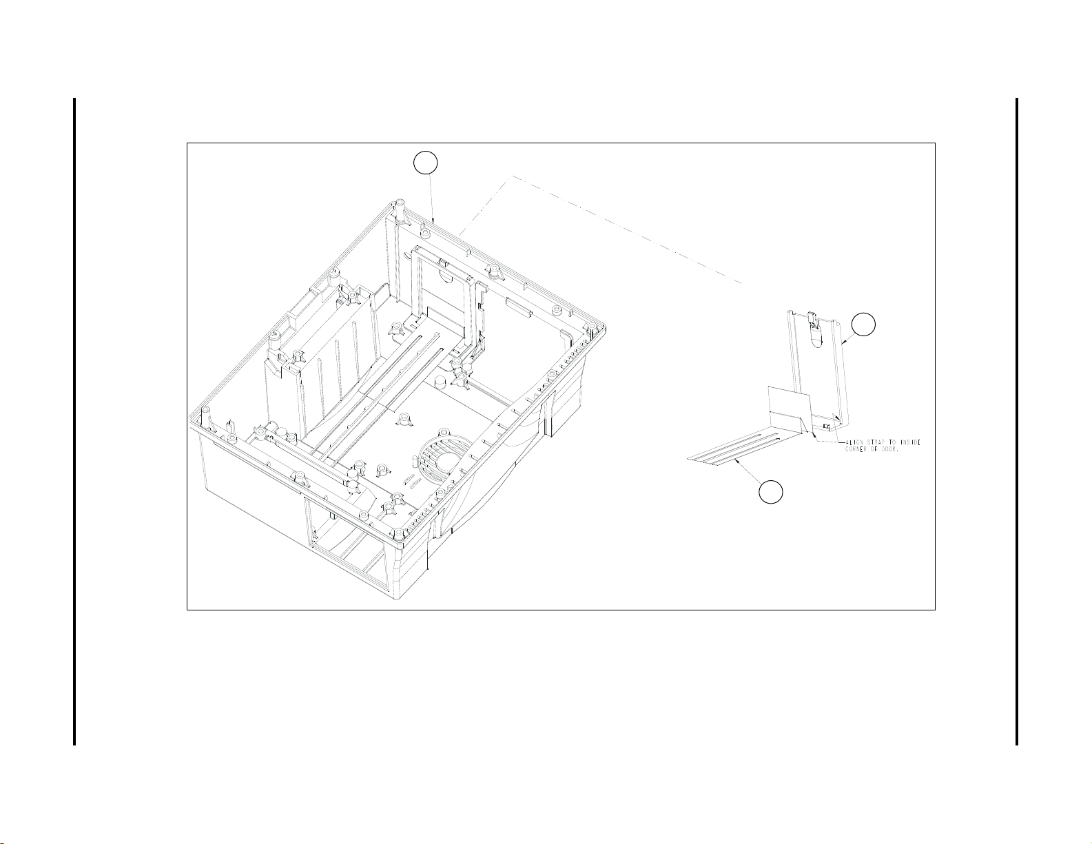
Spectrum
43
1
20
3.4 Rear Housing Assembly
®
/Spectrum OR
™
Service Manual 0070-10-0556-02 3 - 9
Isometric Drawings and Part List Rear Housing Assembly
FIGURE 3-4 Rear Housing Assembly
Page 69

DETAIL A
DETAIL B
28
3
10
9
6
7
24
21
1
14
4
6
28
23
38
1
21
28
14
4
10a
3 - 10 0070-10-0556-02 Spectrum
Rear Housing Assembly Isometric Drawings and Part List
®
/Spectrum OR
™
Service Manual
FIGURE 3-5 Rear Housing Assembly (Sealed Lead Acid battery configuration)
Page 70
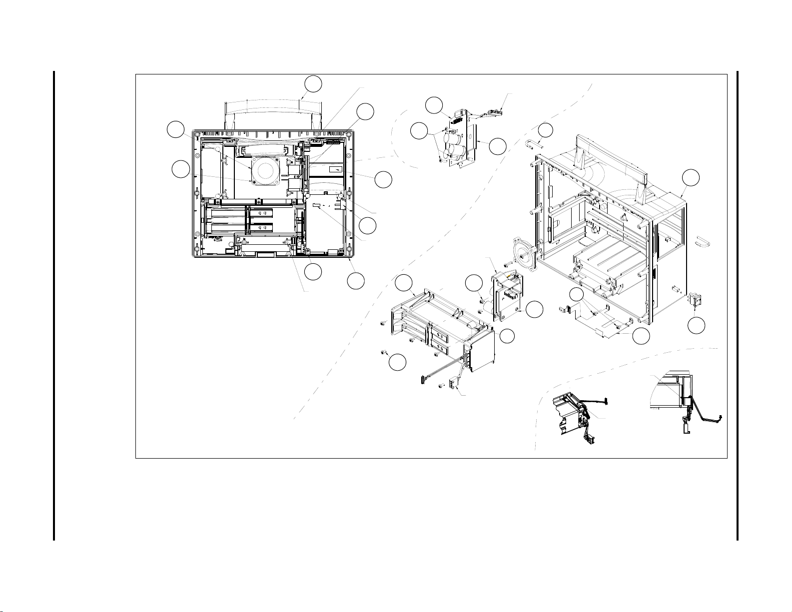
SCALE 0.750
10
10a
(0212-12-0609)
2 PLACES
14
ALIGN HOLE
IN ITEM 21 (BRACKET) WITH
HOLE IN ITEM 1 (HOUSING)
3
1
(0212-12-0603)
2 PLACES
ALIGN UNUSED
TERMINAL AS SHOW N
ATTACH CONNECTOR PART
OF ITEM 14 TO J13
OF ITEM 12 (SEE SHEET 3)
ATTACH CONNECTOR PART
OF ITEM 10 TO J3 OF
ITEM 7
21
REF
28
REF
1
14
21
4
REF
6
28
23
(0012-12-0605)
5 PLACES
28
REF
REF
REF
(0212-12-0603)
2 PLACES
ATTACH CONNECTOR PART
OF ITEM 38 TO J21 OF
ITEM 12
2 PLACES
SEE DETAIL B
(0212-12-0603)
REF
38
85
CLEAN
SURFACE OF HOUSING
WITH
ISOPROPYL ALCOHOL AND
LET DRY. THEN
REMOVE RELEASE
LINER
FROM CLAMP AND INSTALL
ONTO
HOUSING.
FOR LITHIUM-ION ONLY
24
6
7
ATTACH CONNECTOR PART
0F ITEM 7 TO J8
OF ITEM 12 (SEE SHEET 3)
DETAIL B
SCALE 0.750
ORIENT FAN LABEL
SIDE DOWN WITH
CABLE EXIT AS
SHOWN
(0212-12-0607)
3 PLACES
(0012-00-1231)
LITHIUM-ION
BATTERY HOLDER
ROUTE
CABLE THRU
CABLE
CLAMP
AS
SHOWN
CONNECT
TO
POWER SUPPLY
LOCATE
CABLE CLAMP
AS
SHOWN OPENING
THIS
SIDE
9
28
3
10
9
6
7
24
21
1
14
6
28
23
38
1
21
28
14
4
10a
80
Spectrum
/Spectrum OR
Service Manual 0070-10-0556-02 3 - 11
Isometric Drawings and Part List Rear Housing Assembly
®
™
FIGURE 3-6 Rear Housing Assembly (Lithium-Ion battery configuration)
Page 71
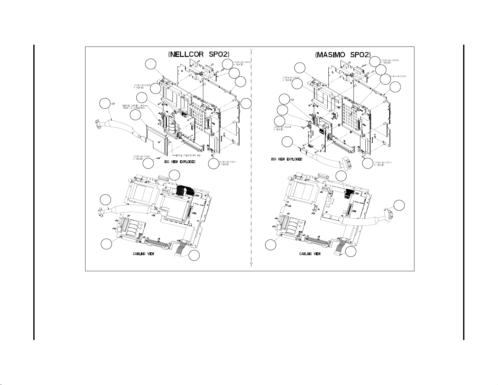
3 - 12 0070-10-0556-02 Spectrum
40
33
40
44
11
30
32
27
31
29
12
5
25
35
34
29
36
12
37
11
27
35
37
25
5
42
13
18
13
18
33
Rear Housing Assembly Isometric Drawings and Part List
®
/Spectrum OR
™
Service Manual
FIGURE 3-7 Rear Housing Assembly (For use with Spectrum P/N 0998-00-1000-XXXXX only)
Page 72

Spectrum
72
73
74
75
76
30
72
31
73
74
33
75
76
13
29
11
5
40
29
18
27
12
32
31a
36
37
34
29
29
29
11
12
18
27
5
13
32
79
®
/Spectrum OR
™
Service Manual 0070-10-0556-02 3 - 13
Isometric Drawings and Part List Rear Housing Assembly
FIGURE 3-8 Rear Housing Assembly
(For use with Spectrum P/N 0998-00-1000-XXXXX only)
FIGURE 3-9 Rear Housing Assembly
(For use with Spectrum P/N 0998-00-1000-XXXXX and
Spectrum OR P/N 0998-00-1500-XXXXX)
Page 73

3 - 14 0070-10-0556-02 Spectrum
77
30
33
(Nellcor SpO Oximax)
2
11
77
40
25
27
18
13
12a
31a
30a
33a
78
Rear Housing Assembly Isometric Drawings and Part List
®
/Spectrum OR
™
Service Manual
FIGURE 3-10 Rear Housing Assembly
(For use with Spectrum P/N 0998-00-1000-XXXXX and Spectrum OR P/N 0998-00-1500-XXXXX)
Page 74
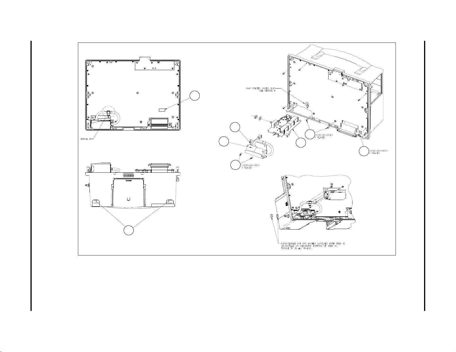
Spectrum
9
47
2
26
47
17
16
15
®
/Spectrum OR
™
Service Manual 0070-10-0556-02 3 - 15
Isometric Drawings and Part List Rear Housing Assembly
FIGURE 3-11 Rear Housing Assembly
Page 75

3 - 16 0070-10-0556-02 Spectrum
22
39
28 19
Rear Housing Assembly Isometric Drawings and Part List
®
/Spectrum OR
™
Service Manual
FIGURE 3-12 Rear Housing Assembly (Sealed Lead Acid battery configuration)
Page 76

Spectrum
22
39
28
19
®
/Spectrum OR
™
Service Manual 0070-10-0556-02 3 - 17
Isometric Drawings and Part List Rear Housing Assembly
FIGURE 3-13 Rear Housing Assembly (Lithium-Ion battery configuration)
Page 77
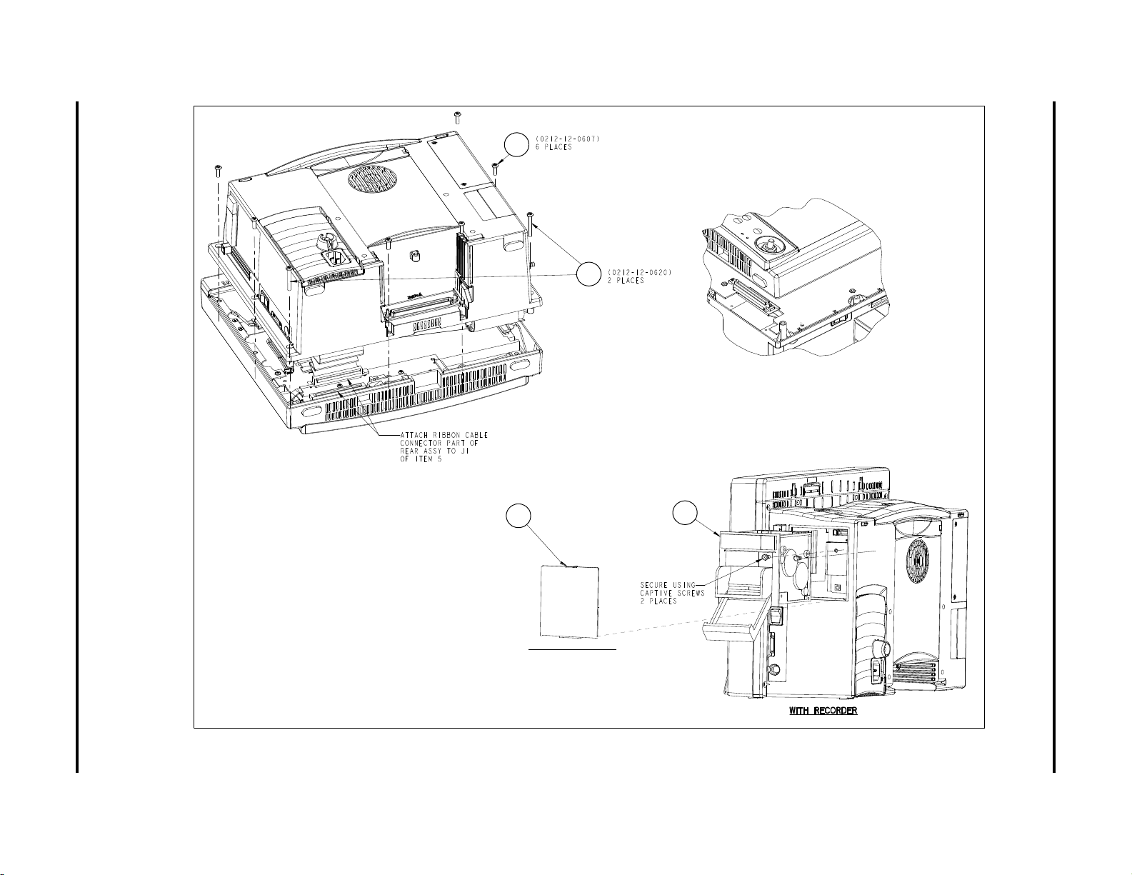
3 - 18 0070-10-0556-02 Spectrum
WITHOUT RECORDER
49
50
49
50
45
46
Rear Housing Assembly Isometric Drawings and Part List
®
/Spectrum OR
™
Service Manual
FIGURE 3-14 Rear Housing Assembly
Page 78
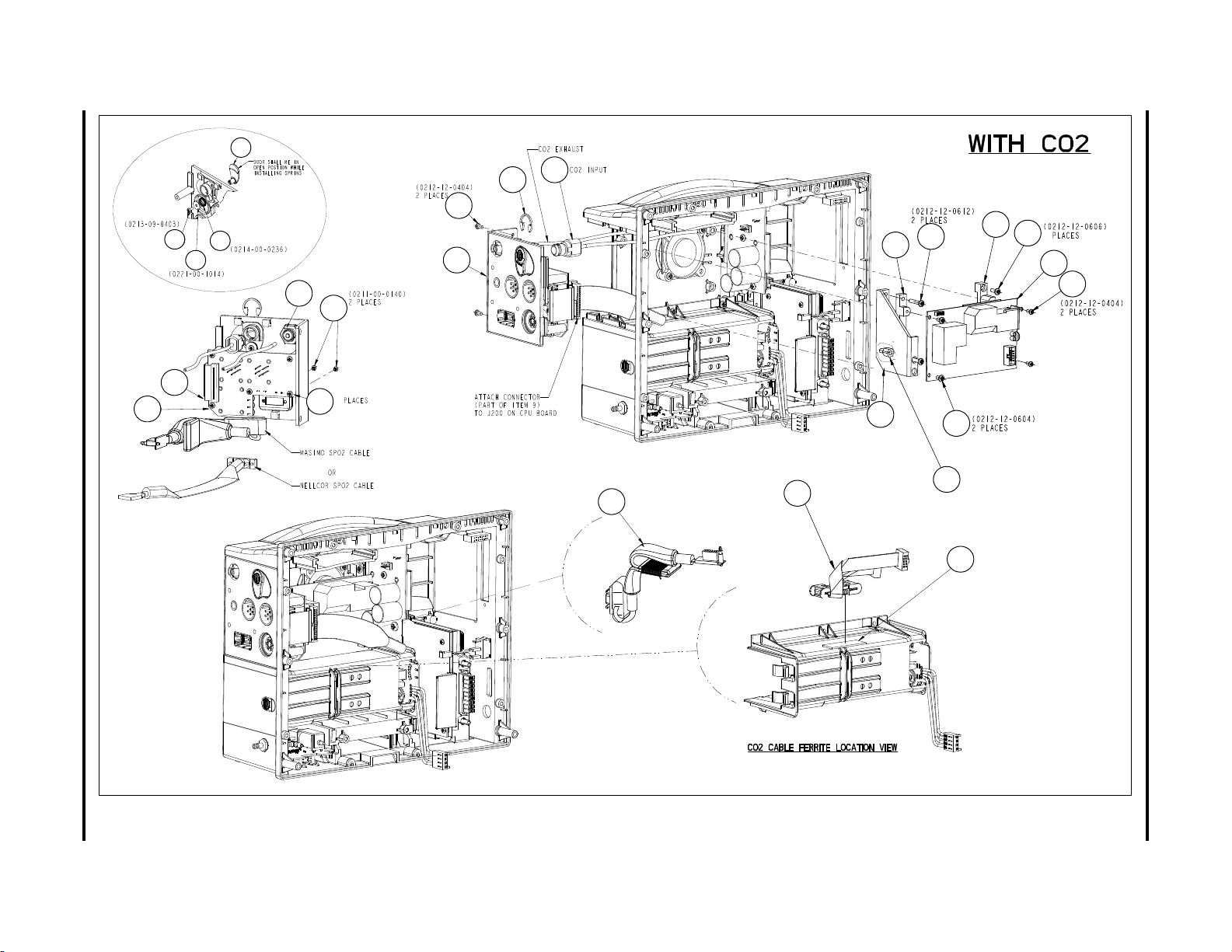
Spectrum
47
48
53
47
70
57
59
56
58
51
60
55
67
69
68
62
64
66
65
63
41
5
(0212-12-0405)
Note: Bracket is only
required on units with
Masimo SPo2
54
Note: Standoffs are only
required on units with
Nellcor SPo2. Use item # 60 screw
to secure.
4
71
52
37
67
68
69
62
66
52
63
64
65
54
53
55
57
70
59
47
41
48
56
47
60
51
58
71
37
®
/Spectrum OR
™
Service Manual 0070-10-0556-02 3 - 19
Isometric Drawings and Part List Rear Housing Assembly
FIGURE 3-15 Rear Housing Assembly (Sealed Lead Acid battery configuration)
Page 79

47
55
64
63
65
55
47
48
63
64
65
61
3 - 20 0070-10-0556-02 Spectrum
Rear Housing Assembly Isometric Drawings and Part List
®
/Spectrum OR
™
Service Manual
FIGURE 3-16 Rear Housing Assembly (Sealed Lead Acid battery configuration)
Page 80
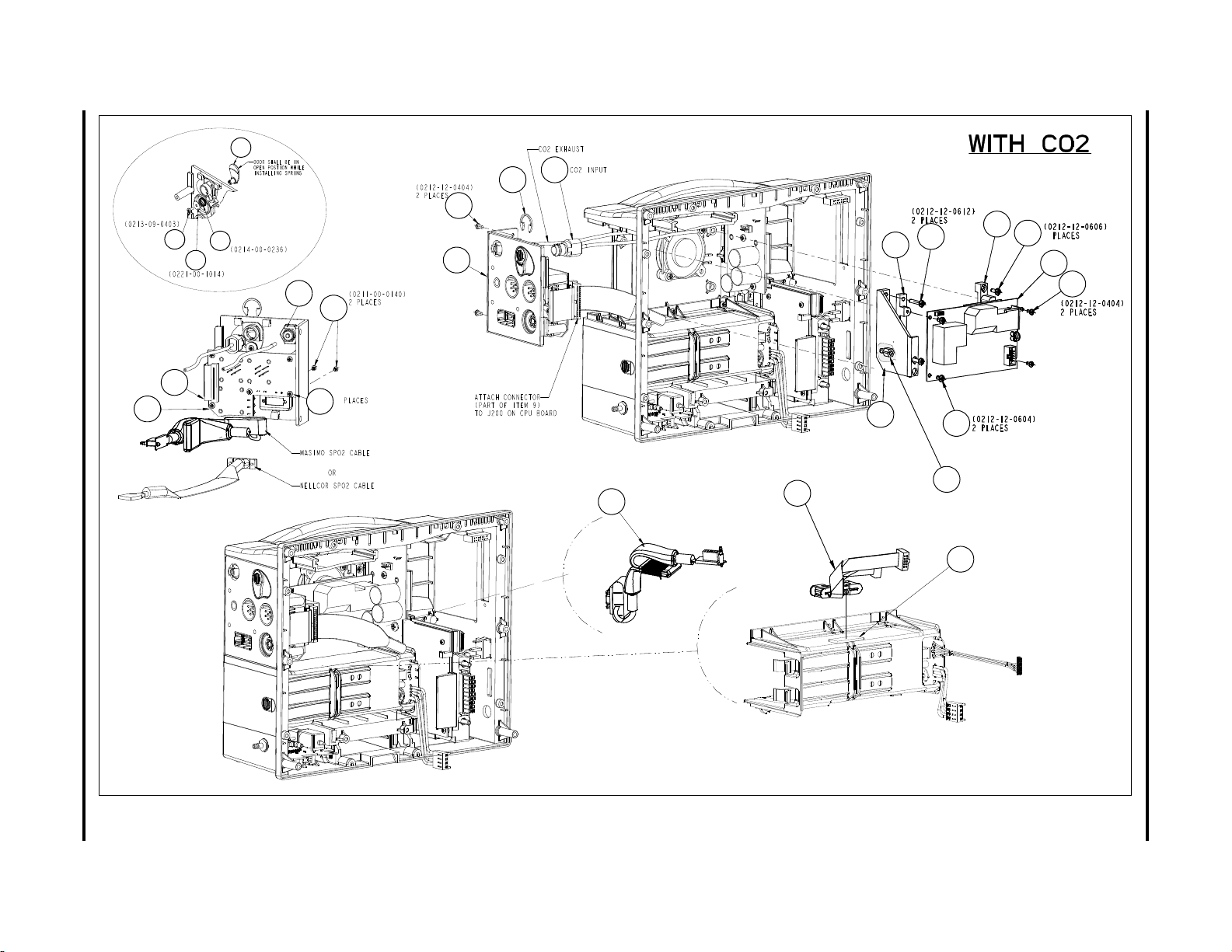
Spectrum
48
67
69
68
62
64
66
65
63
5
(0212-12-0405)
47
53
47
70
57
59
58
51
60
55
41
Note: Bracket is only
required on units with
Masimo SPo2
54
Note: Standoffs are only
required on units with
Nellcor SPo2. Use item # 60 screw
to secure.
4
71
37
52
56
67
68
69
62
66
52
63
64
65
54
53
55
57
70
59
47
41
48
56
47
60
51
58
71
37
®
/Spectrum OR
™
Service Manual 0070-10-0556-02 3 - 21
Isometric Drawings and Part List Rear Housing Assembly
FIGURE 3-17 Rear Housing Assembly (Lithium-Ion battery configuration)
Page 81

3 - 22 0070-10-0556-02 Spectrum
61
48
47
55
64
63
65
55
47
48
63
64
65
61
Rear Housing Assembly Isometric Drawings and Part List
®
/Spectrum OR
™
Service Manual
FIGURE 3-18 Rear Housing Assembly (Lithium-Ion battery configuration)
Page 82

Isometric Drawings and Part List Rear Housing Assembly
ITEM NO DESCRIPTION PART NUMBER
1 Rear Housing 0380-00-0339-04
2 Foot 0348-00-0190
3 Handle 0367-00-0061
4 Pin Handle 0226-00-0017
5 PCB Assembly, Module Interface 0670-00-1155-01
6 Bracket Recorder Mounting (AR-42) 0406-00-0741
7 PCB Assembly, Recorder Interface 0670-00-0695
9 Label, Part Number/Serial Number N/A
10 Fan Assembly w/Cable 9.89 CFM 0012-00-1622-01
10a Screw, Pan Head Cross Recessed #6-32 x 9/16 0012-12-0609
11 Plate Ground 0386-00-0290
12 PC Board Assembly Main/CPU TFT
0670-00-0782-02
(Use with S/N MM XXXX-XX)
12a PC Board Assembly Main/CPU TFT
0670-00-0782-01
(Use with S/N MS XXXX-J5 or above)
13 Cable Main Board to Interconnect Board 0012-00-1210
14 Cable Assembly Power Switch 0012-00-1231
15 PCB Assembly, NIBP module 0670-00-0746-01
15 NIBP Module Assembly 0670-00-0798-01
16 Cable Assembly Pump NIBP 0012-00-1249
17 Bracket Pump 0406-00-0750
18 Cable NIBP to Main Board 0012-00-1211
19 Cover Power Supply 0198-00-0051
20 Door Battery Access 0380-00-0349
21 Strap Grounding Plastic Battery Holder 0346-00-0049
22 Cover Transceiver 0198-00-0027
23 Screw, Pan Head Cross Recessed #6-32 x 5/16 0212-12-0605
24 Screw, Pan Head Cross Recessed #6-32 x 7/16 0212-12-0607
25 Screw, Pan Head Cross Recessed #4-40 x 3/8 0212-12-0406
26 Screw, Pan Head Cross Recessed #4-40 x 3/4 0212-12-0412
27 Screw, Pan Head Cross Recessed #4-40 x 7/16 0212-12-0407
28 Screw, Pan Head Cross Recessed #6-32 x 3/16 0212-12-0603
29 Screw, Pan Head Cross Recessed #4-40 x 1/2 0212-12-0408
30 SpO
30a SpO
Board Assembly Nellcor® 304P 0671-00-0162
2
Board Assembly Nellcor® OxiMax 0671-00-0066
2
31 PCB Assembly Nellcor Interface 0670-00-0696
31a PCB Assembly Masimo/Nellcor Interface Bd
0670-00-0785-XX
(use with CPU Bd 0670-00-0782-XX only)
32 Cable, Nellcor SpO
33 Cable Assembly, Nellcor SpO
33a Cable Assembly, Nellcor SpO
34 SpO
Board Assembly Masimo® MS-3 0671-00-0055
2
35 Cable, Masimo SpO
Interface Bd to Main Bd 0012-00-1233
2
2
OxiMax 0012-00-1634
2
to Main Board 0012-00-1201
2
0012-00-1356
36 Spacer Nylon Richco 0361-45-0403
Spectrum®/Spectrum OR™ Service Manual 0070-10-0556-02 3 - 23
Page 83

Rear Housing Assembly Isometric Drawings and Part List
ITEM NO DESCRIPTION PART NUMBER
37 Cable Assembly, Masimo SpO
with Choke 0012-00-1308
2
38 Battery Holder Assembly, Plastic, Sealed Lead Acid 0997-00-0972-01
38 Battery Holder Assembly, Plastic, Lithium-Ion 0997-00-0972-02
39 Power Supply/Charger (Sealed Lead Acid) 0014-00-0250
39 Power Supply/Charger (Lithium-Ion) 0014-00-0251
40 Screw, Pan Head Cross Recessed #4.40 x 3/16 0212-12-0403
41 CO
Input Assembly 0012-00-1400
2
42 Screw, Pan Head, Nylon #4.40 x 1/4 0212-01-0404
43 Strap, Battery Door 0346-00-0047
44 Insulator, Nellcor SpO
, Interface Board 0349-00-0322
2
45 Screw, Pan Head Cross Recessed #6.32 x 1 1/4 0212-12-0620
46 Screw, Pan Head Cross Recessed #6.32 x 5/8 0212-12-0610
47 Screw, Pan Head Cross Recessed #4.40 x 1/4 0212-12-0404
48 Screw, Metric Flat Head 0211-00-0140
49 Recorder Thermal Array (AR-42 Special) 0683-00-0465-01
50 Recorder Plate, Blank 0370-00-0017-03
51 MediCO
miniMediCO
Module Assembly (Oridion)
2
52 Cable CO
52 Cable CO
53 Retainer CO
Module Assembly (Oridion)
2
to Main Board (MediCO2) 0012-00-1200
2
to Main Board (miniMediCO2) 0012-00-1683-01
2
Connector 0226-00-0018
2
0671-00-0164-03
0671-00-0089-01
54 Standoff Hex Male/Female #6.32 x 0.250 long 0361-27-0250
55 Connector Panel Masimo w/CO
55 Connector Panel Masimo w/o CO
55 Connector Panel Nellcor w/CO
55 Connector Panel Nellcor w/o CO
2
2
2
2
55 Connector Panel Nellcor Oximax w/ CO
55 Connector Panel Nellcor Oximax w/o CO
2
2
0380-00-0348-01
0380-00-0348-02
0380-00-0348-03
0380-00-0348-04
0380-00-0348-05
0380-00-0348-06
56 Tape Double-sided 5/8 wide 0215-00-0115
57 Bracket CO
57 Bracket CO
58 Bracket CO
58 Bracket CO
Mounting Thru-Hole End (MediCO2) 0406-00-0783
2
Mounting Upper (miniMediCO2) 0406-00-0879
2
Mounting Slotted End (MediCO2) 0406-00-0805
2
Mounting Lower (miniMediCO2) 0406-00-0885
2
59 Screw, Pan Head Cross Recessed #6.32 x 1/4 0212-12-0604
60 Screw, Pan Head Cross Recessed #6.32 x 3/8 0212-12-0606
61 Clamp Cable 3/16 Self Adhesive 0343-00-0007
62 Washer, Flat 0.470 OD, 0.119 ID 0221-00-1014
63 PC Board Assembly Patient Connector AAMI w/IBP 0670-00-0682-01
63 PC Board Assembly Patient Connector AAMI w/o IBP 0670-00-0682-02
63 PC Board Assembly Patient Connector HP 0670-00-0680-01
64 Cable Panel to Main Board 0012-00-1206-01
65 Screw, Pan Head Cross Recessed #4.40 x 5/16 0212-12-0405
66 Pneumatic Fitting Male Panel Mount 0103-00-0489
3 - 24 0070-10-0556-02 Spectrum®/Spectrum OR™ Service Manual
Page 84

Isometric Drawings and Part List Rear Housing Assembly
ITEM NO DESCRIPTION PART NUMBER
67 Door, CO2 Connector 0380-00-0355
68 Spring Door 0214-00-0236
69 Screw, Self-Tapping #4-40 x 3/16 0213-09-0403
70 Screw Pan Head Cross Recessed #6 x 3/4 0212-12-0612
71 Bracket Magnetic Shield 0406-00-0833
72 Standoff Plastic 0361-08-0017
73 Cable Tie Anchor 0125-00-0023
74 Washer Shoulder .140 OD, -115 ID 0221-00-1026
75 Screw Pan Head 0212-12-0418
76 Cable Tie 0125-01-0001
77 Standoff Plastic 0361-30-0375
78 Cable, Interface to Main CPU Board for
0998-00-1000-XXXX
79 Standoff 0361-30-0250
80 Clip, Plastic 0343-05-0001
0012-00-1596
Spectrum®/Spectrum OR™ Service Manual 0070-10-0556-02 3 - 25
Page 85

3 - 26 0070-10-0556-02 Spectrum
(0212-12-0420)
2 PLACES
(0212-12-0605)
5 PLACES
2 PLACES
2 PLACES
2 PLACES
2 PLACES
OR
11
13
12
2
7
10
8
14
9
3
5
1
4
15
15
6
16
3.5 External Parameter Module
External Parameter Module Isometric Drawings and Part List
®
/Spectrum OR
™
Service Manual
FIGURE 3-19 External Parameter Module
Page 86

Isometric Drawings and Part List External Parameter Module
ITEM NO DESCRIPTION PART NUMBER
1 Housing, Top, External Module 0380-00-0413
2 Housing, Bottom, External Module 0380-00-0414
3 Gasket Handle 0380-00-0416
4 Handle 0367-00-0061
5 Shaft Precision Increment 1/8 Dia X 1.250 Long 0226-04-0420
6 FFC Assembly Keypad 0331-00-0118
7 PCB Assembly, Main, External Module 0670-00-0734-01
8 PCB Assembly, Connector Panel, External Module 0670-00-0738-01
9 Button Latch External Module 0380-00-0415
10 Spring Compression 0214-00-0234
11 Screw, Pan Head Cross Recessed #4-40 X 1.25 0212-12-0420
12 Screw, Pan Head Cross Recessed #6-32 X 5/16 0212-12-0605
13 Label, Information External Module 0334-00-2583
14 Label, Patient Connector (T2, IBP3, IBP4, CO)
English, Japanese, Br. Portuguese
14 Label, Patient Connector (T2, IBP3, IBP4)
English, German, Italian, Japanese, Br. Portuguese
14 Label, Patient Connector (T2, CO)
English, Dutch, Japanese, Br. Portuguese
14 Label, Patient Connector (T2)
English, German, French, Spanish, Italian, Dutch,
Japanese, Br. Portuguese
14 Label, Patient Connector (T2, IBP3, IBP4, CO)
German
14 Label, Patient Connector (T2, CO)
German
14 Label, Patient Connector (T2, IBP3, IBP4, CO)
French
14 Label, Patient Connector (T2, IBP3, IBP4) French 0334-00-2582-012
14 Label, Patient Connector (T2, CO)
French
14 Label, Patient Connector (T2, IBP3, IBP4, CO)
Spanish
14 Label, Patient Connector (T2, IBP3, IBP4) Spanish 0334-00-2582-017
14 Label, Patient Connector (T2, IBP3, IBP4, CO)
Italian
14 Label, Patient Connector (T2, CO)
Spanish, Italian
14 Label, Patient Connector (T2, IBP3, IBP4, CO)
Dutch
14 Label, Patient Connector (T2, IBP3, IBP4)
Dutch
15 Label, Keypad Filler 0334-00-2624
16 Label, Part Number/Serial Number N/A
0334-00-2582-001
0334-00-2582-002
0334-00-2582-003
0334-00-2582-004
0334-00-2582-006
0334-00-2582-008
0334-00-2582-011
0334-00-2582-013
0334-00-2582-016
0334-00-2582-021
0334-00-2582-023
0334-00-2582-026
0334-00-2582-027
Spectrum®/Spectrum OR™ Service Manual 0070-10-0556-02 3 - 27
Page 87

3 - 28 0070-10-0556-02 Spectrum
9
8
7
1
3
2
6
5
4
6
5
2
4
1
3
7
9
8
3.6 Comm-Port
Comm-Port Isometric Drawings and Part List
®
/Spectrum OR
™
Service Manual
FIGURE 3-20 Comm-Port
Page 88

Spectrum
10
11
12
13
11
14
3
1
2
6
5
4
4
5
6
2
1
3
16
15
11
4
3
1
2
6
5
12
11
1
2
3
4
5
6
2
3
4
5
6
1
13
11
14
10
1
3
2
5
6
4
15
16
8
®
/Spectrum OR
™
Service Manual 0070-10-0556-02 3 - 29
Isometric Drawings and Part List Comm-Port
FIGURE 3-21 Comm-Port
Page 89

Comm-Port Isometric Drawings and Part List
ITEM NO DESCRIPTION PART NUMBER
1 Housing, Top, Comm-Port 0380-00-0346
2 Screw, Pan Head, #4-40 X 5/16 0212-12-0405
3 Screw, Captive, Pan Head, Cross Recessed 0217-02-0004
4 Socket, Guide, Docking Connector 0132-00-0077
5 Label, Information, Comm-Port 0334-00-1533
6 Label N/A
7 PCB Assembly, Comm-Port, CS1/MB1/RD1 0670-00-0690
8 Housing, Bottom, Comm-Port, -03 and -04 0380-00-0347-03
9 Label, "CS1, MB1, RD1", Comm-Port 0334-00-1536
10 PCB Assembly, Comm-Port, RD1/NC1/SP1 0670-00-0692
11 Housing, Bottom, Comm-Port, -05 and -06 0380-00-0347-04
12 Label, "RD1, NC1, SP1", Comm-Port 0334-00-1573
13 PCB Assembly, Comm-Port, SP1/NC1/SP2 0670-00-1140
14 Label, "SP1, NC1, SP2", Comm-Port 0334-00-2521
15 Label, "CS1, MB1, SP1", Comm-Port 0334-00-1541
16 PCB Assembly, Comm-Port, CS1/MB1/SP1 0670-00-0684-01
3 - 30 0070-10-0556-02 Spectrum®/Spectrum OR™ Service Manual
Page 90

Spectrum
35
1
7
5
9
3
4
2
6
18
24
15
30
28
29
33
20
27
22
26
16
35
32
17
®
/Spectrum OR
™
Service Manual 0070-10-0556-02 3 - 31
Isometric Drawings and Part List Comm-Port
FIGURE 3-22 Base Station
Page 91

3 - 32 0070-10-0556-02 Spectrum
36
7
23
33
9
3
8
20
20
20
11
10
14
19
18
29
31
36
21
25
12
13
34
Comm-Port Isometric Drawings and Part List
®
/Spectrum OR
™
Service Manual
FIGURE 3-23 Base Station Assembly
Page 92

Isometric Drawings and Part List Comm-Port
ITEM NO DESCRIPTION PART NUMBER
1 Housing Top Base Station 0380-00-0340
2 Housing Bottom Base Station 0380-00-0341
3 Latch Base Station 0380-00-0342
4 Lever Base Station 0380-00-0343
5 Carriage Base Station 0380-00-0344
6 Bezel Base Station 0380-00-0323
7 Connector Panel Rear 0386-00-0323
8 Slide Dashpot (Plastic Part) 0406-00-0737
9 PCB Assy Main Board 0670-00-0758-01
10 PCB Assy Daughter Board 0670-00-0759-01
11 Standoff Hex Male/Female (4-40 x .748 Lg) 0361-00-0182
12 Dashpot 0103-00-0466
13 Bracket Mounting Dashpot Base Station 0406-00-0738
14 Bracket Main Connector Ground 0406-00-0841
15 Pin Monitor Guide 0226-00-0016
16 Tubing Silicone Rubber 3/8 I.D. X 1/16 Wall 0008-00-0321
17 Spring Extension .375 Dia. 1.5 Length 0214-00-0235
18 Spring Compression .296 Dia. 1.281 Length 0214-00-0234
19 Socket Guide Docking Connector 0132-00-0077
20 Screw Pan Hd 4-40 x .25 Lg 0212-12-0404
21 Screw Pan Hd 4-40 x .75 Lg 0212-12-0412
22 Screw Pan Hd 6-32 x .50 Lg 0212-12-0608
23 Screw Pan Hd 6-32 x .31 Lg 0212-12-0605
24 Screw Shoulder #6 Thread .156 Dia x 0.187
Height
25 Nut Plain Hex #4 Small Pattern 0223-02-0004
26 Washer Snubbing Mylar 0221-00-1016
27 Washer Flat Large O.D. #4 0221-00-1010
28 Label Function Diagram Base Station 0334-00-1511
29 Label Information Base Station 0334-00-1497
30 Label Dashpot Adjustment 0334-00-1618
31 Label, Latch, Locked/Unlocked 0334-00-2514
32 Bumper (Feet Base Station) 0348-03-0001
33 Standoff Hex Male/Female With Lock Washer 0361-00-0164
34 Label Part Number Serial Number N/A
35 Power Supply Assembly 0014-00-0070
36 Dashpot Assembly 0103-00-0465
NS MB1 Connector Shroud 0334-00-1668
N.A. Not Available
0217-00-0012
Spectrum®/Spectrum OR™ Service Manual 0070-10-0556-02 3 - 33
Page 93

Comm-Port Isometric Drawings and Part List
This page intentionally left blank.
3 - 34 0070-10-0556-02 Spectrum®/Spectrum OR™ Service Manual
Page 94

4.0
Calibration Procedure
4.1 Introduction
The following procedures are provided to verify the proper operation of the Spectrum®/
Spectrum OR
problems within the Spectrum®/Spectrum OR™ hardware. A menu driven interface
similar to that of the Spectrum
tests.
™
Monitor. Service Diagnostics provide the capability of diagnosing
®
/Spectrum OR™ User Interface, is used to execute all
CAUTION: Calibration is not to be performed while monitoring a
patient.
4.2 Warning and Guidelines
In the event that the instrument covers are removed, observe the following warnings and
general guidelines:
1. Do not short component leads together.
2. Perform all steps in the exact order given.
3. Use extreme care when reaching inside the opened instrument. Do not contact exposed
metal parts which may become electrically active.
4. Read and understand each step of the procedure prior to beginning the step.
Spectrum®/Spectrum OR™ Service Manual 0070-10-0556-02 4 - 1
Page 95

Test Equipment and Special Tools Required Calibration Procedure
4.3 Test Equipment and Special Tools Required
• Digital Mercury manometer with bulb and valve 0-500 mmHg - Netech Digimano Accuracy 0.25% Full Range
• Test Chamber/
Dummy Cuff
•DVM
• Patient Simulator
• Digital Flow Meter
• Safety Analyzer Dempsy Model or equivalent
• BISx BIS Sensor Simulator P/N 0454-00-0060
P/N 0138-00-0001-01 (700 cc) or -03 (500 cc)
4 - 2 0070-10-0556-02 Spectrum®/Spectrum OR™ Service Manual
Page 96

Calibration Procedure Diagnostics
4.4 Diagnostics
To enter the diagnostic mode:
1. Turn the power OFF.
2. Pressing and hold the FREEZE key (Spectrum®) or the SPIROMETRY key
(Spectrum OR
will appear on screen. Release the FREEZE key or the SPIROMETRY key.
3. Rotate the Navigator™ Knob to move the cursor within the Diagnostics Main
Menu. Pressing the Navigator knob will select the desired test and open the second
test menu.
™
) while powering ON the monitor. The Diagnostics Main Menu
FIGURE 4-1 Diagnostics Main Menu
FIGURE 4-2 Diagnostics Test Menu
Spectrum®/Spectrum OR™ Service Manual 0070-10-0556-02 4 - 3
Page 97

Diagnostics Calibration Procedure
Keypad / Control Knob Test
Press keys and the text will appear on screen. Rotate the control knob to move the cursor. Press and hold the Normal Screen Key to exit.
Key Pressed: None
Control Knob Detent:
4.4.1 Keypad / Control Knob Test
When this menu is selected the unit will perform an echo test by displaying the name of the
key that was pressed.
1. A blank key name will appear on screen
2. When a key is pressed the name of that key will be displayed in the key name window.
3. Exercise each key to verify proper operation.
4. A second window with blank boxes will be displayed on screen.
5. When rotating the control knob the blank boxes will illuminate with each active detent.
6. Press the PRINT key to print the test result via the internal recorder.
7. Press the NORMAL key and hold to return to the Diagnostics Test Menu.
FIGURE 4-3 Keypad / Control Knob Test
4 - 4 0070-10-0556-02 Spectrum®/Spectrum OR™ Service Manual
Page 98

Calibration Procedure Diagnostics
4.4.2 Recorder Test
Select the Chart Grid ASCII Characters menu.
FIGURE 4-4 Recorder Test Menu
The printer will print the Recorder Test pattern as shown in the figure below.
FIGURE 4-5 Recorder Test Strip
Spectrum®/Spectrum OR™ Service Manual 0070-10-0556-02 4 - 5
Page 99

Diagnostics Calibration Procedure
4.4.3 Display Tests
The display test offers the choice of a Pixel Test or a Color Test.
FIGURE 4-6 Display Tests Menu
4.4.4 Pixel Test
The pixel test will verify the proper operation the display. On screen one half of the screen
will be illuminated, the second half will be black. Pressing the Navigator
illuminate the second half of the screen, the first half will be black. Pressing the Navigator
knob a third time will activate the Display Test Menu screen.
FIGURE 4-7 Pixel Test Menu
™
knob will
4 - 6 0070-10-0556-02 Spectrum®/Spectrum OR™ Service Manual
Page 100

Calibration Procedure Diagnostics
White
Red
Blue
Green
4.4.5 Color Test
The color test will verify the four basic colors of the display. Press the Navigator™ knob to
view the selected color screens in full illumination. The colors are Red, Blue, Green and
White.
FIGURE 4-8 Color Test
Spectrum®/Spectrum OR™ Service Manual 0070-10-0556-02 4 - 7
 Loading...