

Page 1

BS-120/BS-130/BS-180/BS-190
Chemistry Analyzer
Service Manual
Page 2

i
© 2007-2010 Shenzhen Mindray Bio-medical Electronics Co., Ltd. All rights
Reserved.
For this Service Manual, the issued Date is 2010-04 (Version: 4.0).
Intellectual Property Statement
SHENZHEN MINDRAY BIO-MEDICAL ELECTRONICS CO., LTD. (hereinafter called
Mindray) owns the intellectual property rights to this Mindray product and this manual.
This manual may refer to information protected by copyrights or patents and does not
convey any license under the patent rights of Mindray, nor the rights of others.
Mindray does not assume any liability arising out of any infringements of patents or
other rights of third parties.
Mindray intends to maintain the contents of this manual as confidential information.
Disclosure of the information in this manual in any manner whatsoever without the
written permission of Mindray is strictly forbidden.
Release, amendment, reproduction, distribution, rent, adaption and translation of this
manual in any manner whatsoever without the written permission of Mindray is strictly
forbidden.
, , , , , are the
registered trademarks or trademarks owned by Mindray in China and other countries.
All other trademarks that appear in this manual are used only for editorial purposes
without the intention of improperly using them. They are the property of their
respective owners.
Responsibility on the Manufacturer Party
Contents of this manual are subject to changes without prior notice.
All information contained in this manual is believed to be correct. Mindray shall not be
liable for errors contained herein nor for incidental or consequential damages in
connection with the furnishing, performance, or use of this manual.
Mindray is responsible for safety, reliability and performance of this product only in
the condition that:
all installation operations, expansions, changes, modifications and repairs of this
product are conducted by Mindray authorized personnel;
the electrical installation of the relevant room complies with the applicable
national and local requirements;
the product is used in accordance with the instructions for use.
Upon request, Mindray may provide, with compensation, necessary circuit diagrams,
calibration illustration list and other information to help qualified technician to maintain
and repair some parts, which Mindray may define as user serviceable.
Page 3

ii
Warranty
THIS WARRANTY IS EXCLUSIVE AND IS IN LIEU OF ALL OTHER WARRANTIES,
EXPRESSED OR IMPLIED, INCLUDING WARRANTIES OF MERCHANTABILITY
OR FITNESS FOR ANY PARTICULAR PURPOSE.
Exemptions
WARNING:
It is important for the hospital or organization that employs this
equipment to carry out a reasonable service/maintenance plan.
Neglect of this may result in machine breakdown or injury of human
health.
NOTE:
This equipment is to be operated only by medical professionals trained
and authorized by Mindray or Mindray-authorized distributors.
Mindray's obligation or liability under this warranty does not include any
transportation or other charges or liability for direct, indirect or consequential
damages or delay resulting from the improper use or application of the product or the
use of parts or accessories not approved by Mindray or repairs by people other than
Mindray authorized personnel.
This warranty shall not extend to:
any Mindray product which has been subjected to misuse, negligence or
accident;
any Mindray product from which Mindray's original serial number tag or product
identification markings have been altered or removed;
any product of any other manufacturer.
Return Policy
Return Procedure
In the event that it becomes necessary to return this product or part of this product to
Mindray, the following procedure should be followed:
Obtain return authorization: Contact the Mindray Service Department and obtain
a Customer Service Authorization (Mindray) number. The Mindray number must
appear on the outside of the shipping container. Returned shipments will not be
accepted if the Mindray number is not clearly visible. Please provide the model
number, serial number, and a brief description of the reason for return.
Freight policy: The customer is responsible for freight charges when this product
is shipped to Mindray for service (this includes customs charges).
Return address: Please send the part(s) or equipment to the address offered by
Customer Service department.
Page 4

iii
Company Contact
Manufacturer: Shenzhen Mindray Bio-Medical Electronics Co., Ltd.
Address:
Mindray Building, Keji 12th Road South, Hi-tech Industrial Park,
Nanshan, ShenZhen 518057, P.R.China,
Tel:
Fax:
+86 755 26582479 26582888
+86 755 26582934 26582500
Page 5

iv
Page 6
Who Should Read This Manual
This manual is geared for service personnel authorized by Mindray.
What Can You Find in This Manual
This manual covers principles, installation procedures, theories, maintenance and
troubleshooting guidelines of the BS-120/BS-130/BS-180/BS-190. Please service the
system strictly as instructed by this manual.
Conventions Used in This Manual
Foreword
This manual uses the following typographical conventions to clarify meanings in the
text.
Bold and Italic font indicates text displayed on the screen, such as Sample
Request.
Safety Symbols
In this manual, the signal words
and NOTE are used regarding safety and other important instructions. The signal
words and their meanings are defined as follows. Please understand their meanings
clearly before reading this manual.
When you see… Then…
WARNING
BIOHAZARD
CAUTION
Read the statement following the symbol. The
statement is alerting you to an operating hazard that
can cause personal injury.
Read the statement following the symbol. The
statement is alerting you to a potentially
biohazardous condition.
Read the statement following the symbol. The
statement is alerting you to a possibility of system
damage or unreliable results.
BIOHAZARD, WARNING, CAUTION
NOTE
Read the statement following the symbol. The
statement is alerting you to information that requires
your attention.
1
Page 7
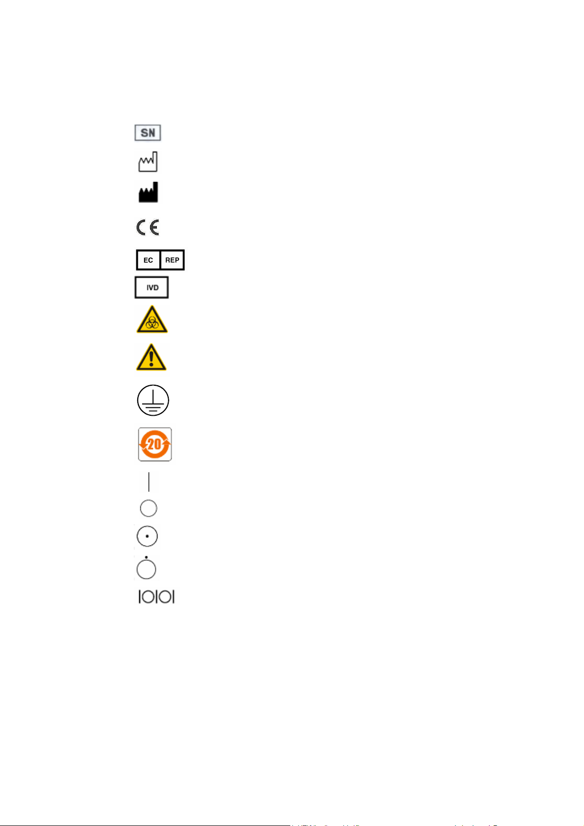
Labels Used On the System
The labels attached to the panels of the system use symbols to clarify the meaning of
the text. The chart below explains the symbols on the labels.
Serial Number
Date of Manufacture
Manufacturer
CE marking. The device is fully in conformity with the Council
Directive Concerning In Vitro Diagnostic Medical Devices
98/79/EC.
Authorized Representative in the European Community
In Vitro diagnostic equipment
Biohazard warning: Risk of potentially biohazardous infection
Warning: Risk of personal injury or equipment damage
Protective ground terminal
Time limit in use for environmental protection (20 years)
ON (Main Power)
OFF (Main Power)
ON (Power)
OFF (Power)
Serial communication port
Graphics
All graphics, including screens and printout, are for illustration purposes only and
must not be used for any other purpose.
2
Page 8

EC Representative
Name: Shanghai International Holding Corp. GmbH(Europe)
Address:
Eiffestrasse 80 D-20537 Hamburg Germany
Tel:
Fax:
+49 40 2513174
+49 40 255726
3
Page 9
Safety Precautions
Observe the following safety precautions when using the Chemistry Analyzer.
Ignoring any of these safety precautions may lead to personal injury or equipment
damage.
WARNING
If the system is used in a manner not specified by Mindray, the
protection provided by the system may be impaired.
Preventing Electric Shock
Please observe the following instructions to prevent electric shock.
WARNING
When the Main Power is on, users must not open the rear cover or
side cover.
Spillage of reagent or sample on the analyzer may cause equipment
failure and even electric shock. Do not place sample and reagent on
the analyzer.
Preventing Personal Injury Caused by Moving Parts
Please observe the following instructions to prevent personal injury caused by
moving parts.
WARNING
Do not touch the moving parts when system is in operation. The
moving parts include sample probe, mixing bar, sample/reagent disk
and reaction disk.
Do not put your finger or hand into any open part when the system is
in operation.
Preventing Personal Injury Caused by Photometer Lamp
Please observe the following instructions to prevent personal injury caused by
photometer lamp.
WARNING
Light sent by the photometer lamp may hurt your eyes. Do not stare
into the lamp when the system is in operation.
If you want to replace the photometer lamp, first switch off the Main
Power and then wait at least 15 minutes for the lamp to cool down
before touching it. Do not touch the lamp before it cools down, or you
may get burned.
4
Page 10
Preventing Infection
Please observe the following instructions to protect against the biohazardous
infection.
BIOHAZARD
Inappropriately handling samples, controls and calibrators may lead
to biohazardous infection. Do not touch the sample, mixture or waste
with your hands. Wear gloves and lab coat and, if necessary,
goggles.
In case your skin contacts the sample, control or calibrator, follow
standard laboratory safety procedure and consult a doctor.
Handling Reagents and Wash Solution
WARNING
Some reagents and wash solution may be corrosive to human skins.
Plaase handle the reagents and concentrated wash solution carefully
and avoid direct contact.In case your skin or clothes contact the
reagents or wash solution, wash them off with water. In case the
reagents or wash solution spill into your eyes, rinse them with much
water and consult an oculist.
Treating Waste Liquids
Please observe the following instructions to prevent environmental pollution and
personal injury caused by waste.
BIOHAZARD
Some substances in reagent, control, enhanced wash solution and
waste are subject to regulations of contamination and disposal.
Dispose of them in accordance with your local or national guidelines
for biohazard waste disposal and consult the manufacturer or
distributor of the reagents for details.
Wear gloves and lab coat and, if necessary, goggles.
Treating Waste Analyzer
Please observe the following instructions to dispose of the waste analyzer.
WARNING
Materials of the analyzer are subject to contamination regulations.
Dispose of the waste analyzer in accordance with your local or
national guidelines for waste disposal.
5
Page 11

Preventing Fire or Explosion
Please observe the following instructions to prevent fire and explosion.
WARNING
Ethanol is flammable substance. Please exercise caution while using
the ethanol.
6
Page 12
Precautions on Use
To use the BS-120/BS-130/BS-180/BS-190 Chemistry Analyzer safely and
efficiently, please pay much attention to the following operation notes.
Intended Use
WARNING
The BS-120/BS-130/BS-180/BS-190 is a fully-automated and
computer-controlled chemistry analyzer designed for in vitro
quantitative determination of clinical chemistries in serum, plasma,
urine and CSF samples. Please consult Mindray first if you want to
use the system for other purposes.
To draw a clinical conclusion, please also refer to the patient’s clinical
symptoms and other test results.
Operator
WARNING
The BS-120/BS-130/BS-180/BS-190 is to be operated only by
clinical professionals, doctors or laboratory experimenters trained by
Mindray or Mindray-authorized distributors.
Environment
CAUTION
Please install and operate the system in an environment specified by
this manual. Installing and operating the system in other environment
may lead to unreliable results and even equipment damage.
Preventing Interference by Electromagnetic Noise
CAUTION
Electromagnetic noise may interfere with operations of the system.
Do not install devices generating excessive electromagnetic noise
around the system. Do not use such devices as mobile phones or
radio transmitters in the room housing the system. Do not use other
CRT displays around the system.The electromagnetic noise might
lead to system failures.
Do not use other medical instruments around the system that may
generate electromagnetic noise to interfere with their operations.
7
Page 13
Operating the System
CAUTION
Operate the system strictly as instructed by this manual.
Inappropriate use of the system may lead to unreliable test results or
even equipment damage or personal injury.
Before using the system for the first time, run the calibration program
and QC program to make sure the system is in normal status.
Be sure to run the QC program every time you use the system,
otherwise the result may be unreliable.
Do not open the covers of the sample/reagent disk cover when the
system is in operation.
Do not open the reaction disk cover when system is in operation.
The RS-232 port on the analyzing unit is to be used for connection
with the operation unit only. Do not use it for other connections. Only
use the supplied cable for the connection.
The operation unit is a personal computer with the
BS-120/BS-130/BS-180/BS-190 operating software installed.
Installing other software or hardware on this computer may interfere
with the system operation. Do not run other software when the
system is working.
Computer virus may destroy the operating software or test data. Do
not use this computer for other purposes or connect it to the Internet.
Do not touch the display, mouse or keyboard with wet hands or
hands with chemicals.
Do not place the Main Power to ON again within 10 seconds since
placing it to OFF; otherwise the system may enter protection status.
If it does so, switch off the Main Power and switch it on again.
Service and Maintenance
CAUTION
Maintain the system strictly as instructed by this manual.
Inappropriate maintenance may lead to unreliable results, or even
equipment damage and personal injury.
Dust may accumulate on the system surface when the system is
exposed to the outside for a long time.To wipe off dust from the
system surface, use a soft, clean and wet (not too wet) cloth, soaked
with mild soap solution if necessary, to clean the surface. Do not use
such organic solvents as ethanol for cleaning. After cleaning, wipe
the surface with dry cloth.
Switch off all the powers and unplug the power cord before cleaning.
Take necessary measures to prevent water ingression into the
system, otherwise it may lead to equipment damage or personal
injury.
Replacement of such major parts as lamp, photometer, sample
probe, mixer and syringe plunger assembly must be followed by a
calibration.
8
Page 14
Setting up the System
CAUTION
To define such parameters as sample volume, reagent volume and
wavelength, follow the instructions in this manual and the package
insert of the reagents.
Samples
CAUTION
Use samples that are completely free of insoluble substances like
fibrin, or suspended matter; otherwise the probe may be
blocked.Medicines, anticoagulants or preservative in samples may
lead to unreliable results.
Medicines, anticoagulants or preservative in the samples may lead to
unreliable results.
Hemolysis, icterus or lipemia in the samples may lead to unreliable
test results, so a sample blank is recommended.
Store the samples properly. Improper storage may change the
compositions of the samples and lead to unreliable results.
Sample volatilization may lead to unreliable results. Do not leave the
sample open for a long period.
Some samples may not be analyzed on the
BS-120/BS-130/BS-180/BS-190 based on parameters the reagents
claim capable of testing. Consult the reagent manufacturer or
distributor for details.
Certain samples need to be processed before being analyzed by the
system. Consult the reagent manufacturer or distributor for details.
The system has specific requirements on the sample volume. Refer
to this manual for details.
Load the sample to correct position on the sample disk before the
analysis begins; otherwise you will not obtain correct results.
9
Page 15
10
Reagents, Calibrators and Controls
CAUTION
Use appropriate reagents, calibrators and controls on the system.
Select appropriate reagents according to performance characteristic
of the system. Consult the reagent suppliers, Mindray or
Mindray-authorized distributor for details, if you are not sure about
your reagent choice.
Store and use reagents, calibrators and controls strictly as instructed
by the suppliers. Otherwise, you may not obtain reliable results or
best performance of the system.
Improper storage of reagents, calibrators and controls may lead to
unreliable results and bad performance of the system even in validity
period.
Perform a calibration after changing reagents. Otherwise, you may
not obtain reliable results.
Contamination caused by carryover among reagents may lead to
unreliable test results. Consult the reagent manufacturer or
distributor for details.
Backing up Data
NOTE
The system can automatically store data to the built-in hard disk of
the PC. However, data loss is still possible due to mis-deletion or
physical damage of the hard disk. Mindray recommends you to
regularly back up the data to portable storage device.
Computer and Printer
NOTE
Refer to the operation manuals of computer and printer for details.
External Equipment
WARNING
External equipment connected to the system, such as PC and printer,
shall be consistent with IEC 60950/EN 60950/ GB4943, EN55022
(Class B) /GB 9254 (Class B) and EN55024/ GB-T 17618.
Page 16

Contents
Intellectual Property Statement ........................................................................................... i
Responsibility on the Manufacturer Party............................................................................ i
Warranty..............................................................................................................................ii
Return Policy .......................................................................................................................ii
Foreword .......................................................................................................................................1
Who Should Read This Manual..........................................................................................1
What Can You Find in This Manual....................................................................................1
Conventions Used in This Manual......................................................................................1
Safety Precautions .............................................................................................................4
Precautions on Use ............................................................................................................7
Contents.........................................................................................................................................I
1
System Description..........................................................................................................1-1
1.1 Overview...............................................................................................................1-1
1.2 System Components ............................................................................................1-1
1.3 Functions ..............................................................................................................1-3
2
System Performace and Workflow ..................................................................................2-1
2.1 Technical Specifications........................................................................................2-1
2.1.1 System Specifications..............................................................................2-1
2.1.2 Specifications for Sample System...........................................................2-2
2.1.3 Specifications for Reagent System..........................................................2-3
2.1.4 Specifications of Reaction System ..........................................................2-4
2.1.5 Specifications of Operation......................................................................2-5
2.1.6 Installation Requirements ........................................................................2-5
2.1.7 Optional Modules.....................................................................................2-6
2.2 Workflow (BS-120/BS-130)...................................................................................2-6
2.2.1 Overview..................................................................................................2-6
2.2.2 Timing......................................................................................................2-6
2.2.3 Test Workflow...........................................................................................2-9
2.2.4 Measuring Points................................................................................... 2-11
2.3 Workflow (BS-180/BS-190).................................................................................2-11
2.3.1 Overview................................................................................................2-11
2.3.2 Timing......................................................................................................2-8
2.3.3 Test Workflow...........................................................................................2-9
3
Installation........................................................................................................................3-1
3.1 Environmental Requirements ...............................................................................3-1
3.2 Installation Requirements.....................................................................................3-2
3.2.1 Space and Accessibility Requirements....................................................3-2
3.2.2 Power Requirements ...............................................................................3-2
3.2.3 Water Supply and Drainage Requirements.............................................3-3
3.3 Installation Procedures.........................................................................................3-3
3.3.1 Unpacking................................................................................................3-3
3.3.2 Installation................................................................................................3-5
3.3.3 Operating Software Installation................................................................3-7
3.3.4 Run Operating Software ..........................................................................3-9
3.3.5 Setting up the System............................................................................3-10
3.3.6 Test ........................................................................................................3-14
Contents I
Page 17

3.3.7 Exit the System......................................................................................3-15
4
Units Description .............................................................................................................4-1
4.1 Enclosure and Panel Unit.....................................................................................4-1
4.1.1 Components.............................................................................................4-1
4.1.2 Dismounting/Mounting of Enclosure Unit ................................................4-2
4.2 Probe Unit.............................................................................................................4-5
4.2.1 Function Introduction ...............................................................................4-5
4.2.2 Components of Probe Unit ......................................................................4-5
4.2.3 Dismounting/mounting Sample Probe Unit..............................................4-6
4.3 Sample/Reagent Disk Unit .................................................................................4-10
4.3.1 Function Introduction .............................................................................4-10
4.3.2 Components of Sample/Reagent Disk Unit...........................................4-10
4.3.3 Dismounting Sample/Reagent Disk Unit ............................................... 4-11
4.4 Reaction Disk Unit ..............................................................................................4-17
4.4.1 Function Introduction .............................................................................4-17
4.4.2 Components of Reaction Disk Unit........................................................4-18
4.4.3 Dismounting Reaction Disk Unit ............................................................4-19
4.5 Mixing Unit..........................................................................................................4-22
4.5.1 Function Introduction .............................................................................4-22
4.5.2 Components of Mixing Unit....................................................................4-22
4.5.3 Dismounting Mixing Unit........................................................................4-23
4.6 Photometric Unit .................................................................................................4-26
4.6.1 Introduction............................................................................................4-26
4.6.2 Components of Photometric Unit...........................................................4-26
4.6.3 Dismounting and Mounting Photometric Unit........................................4-30
4.6.4 Adjustment of Photometer .....................................................................4-32
4.7 Power Supply Unit ..............................................................................................4-38
4.7.1 Function and Components.....................................................................4-38
4.7.2 Dismounting Power Supply Unit............................................................4-38
4.8 ISE Unit (Optional)..............................................................................................4-39
4.8.1 Introduction............................................................................................4-39
4.8.2 Components of ISE Unit ........................................................................4-39
4.8.3 Installling and Removing ISE Unit .........................................................4-40
5
Fluid System....................................................................................................................5-1
5.1 Main Functions .....................................................................................................5-1
5.2 Functional Structure..............................................................................................5-1
5.3 Fluid System Chart ...............................................................................................5-2
5.4 Major Components and Their Functions ..............................................................5-3
5.5 Connectors ...........................................................................................................5-4
5.6 Tubing...................................................................................................................5-5
5.7 Fluid System Connections and Layout.................................................................5-6
5.8 External DI Water Tank and Waste Tank ..............................................................5-8
5.9 Key Components ..................................................................................................5-9
5.9.1 Solenoid Valve.............................................................................................5-9
5.9.2 Check Valve.................................................................................................5-9
5.9.3 Liquid Level Float ......................................................................................5-10
5.9.4 Syringe Assembly......................................................................................5-10
5.9.5 Diaphragm Pump.......................................................................................5-11
5.9.6 Probe .........................................................................................................5-11
5.9.7 Filter.......................................................................................................5-12
6
Hardware System............................................................................................................6-1
6.1 Overview...............................................................................................................6-1
II
Contents
Page 18

6.2 Safety Precautions................................................................................................6-1
6.3 Circuit boards........................................................................................................6-2
6.4 Layout of the Boards.............................................................................................6-4
6.5 Detaching and Assembling Circuit Boards ...........................................................6-4
6.6 Function of the Boards .........................................................................................6-5
6.6.1 Control Framework ..................................................................................6-5
6.6.2 Main Board ..............................................................................................6-5
6.6.3 Drive Board..............................................................................................6-6
6.6.4 Pre-amp Board ........................................................................................6-7
6.6.5 AD Conversion Board..............................................................................6-7
6.6.6 Reagent Refrigeration Board...................................................................6-8
6.6.7 Level Detection Board .............................................................................6-8
6.6.8 Reaction Disk Temperature Sampling Board...........................................6-9
6.6.9 Three Probes Connection Board.............................................................6-9
6.6.10 ISE Power Board ...................................................................................6-9
6.6.11 Heater Voltage Selecting Board.............................................................6-9
6.7 On Board LED Indication......................................................................................6-9
6.8 Power Supply Unit ..............................................................................................6-11
6.8.1 Features of Power Supply Unit..............................................................6-12
6.8.2 Protective Function of Power Supply Unit.............................................6-13
6.8.3 Block Diagram .......................................................................................6-13
6.9 Connection Diagram...........................................................................................6-14
7
Service and Maintenance................................................................................................7-1
7.1 Preparation ...........................................................................................................7-1
7.1.1 Tools.........................................................................................................7-2
7.1.2 Wash Solution..........................................................................................7-2
7.1.3 Others......................................................................................................7-2
7.2 Daily Maintenance ................................................................................................7-3
7.2.1 Checking Remaining Deionized Water....................................................7-3
7.2.2 Emptying Waste Tank ..............................................................................7-3
7.2.3 Checking Connection of Deionized Water...............................................7-4
7.2.4 Checking Connection of Waste Water.....................................................7-4
7.2.5 Checking Syringe.....................................................................................7-4
7.2.6 Checking/Cleaning Sample Probe...........................................................7-5
7.2.7 Checking/Cleaning Mixing Bar ................................................................7-6
7.2.8 Checking Printer/Printing Paper ..............................................................7-6
7.2.9 Checking ISE Unit (Optional)...................................................................7-6
7.3 Weekly Maintenance ............................................................................................7-8
7.3.1 Cleaning Sample Probe...........................................................................7-8
7.3.2 Cleaning Mixing Bar.................................................................................7-9
7.3.3 Cleaning Sample/Reagent Compartment..............................................7-10
7.3.4 Cleaning Panel of Analyzing Unit ..........................................................7-11
7.3.5 Washing Deionized Water Tank.............................................................7-11
7.3.6 Washing Waste Tank .............................................................................7-12
7.4 Monthly Maintenance..........................................................................................7-13
7.4.1 Cleaning Wash pool of Probe................................................................7-13
7.4.2 Cleaning Wash pool of Mixing Bar.........................................................7-14
7.4.3 Cleaning Sample/Reagent Rotor...........................................................7-15
7.5 Three-month Maintenance .................................................................................7-15
7.5.1 Washing Dust Screen............................................................................7-15
7.5.2 Replacing Filter Assemby......................................................................7-17
7.6 Irregular Maintenance.........................................................................................7-18
7.6.1 Checking photoelectric system performance.........................................7-18
Contents III
Page 19

7.6.2 Replacing the lamp................................................................................7-18
7.6.3 Replacing the Filter................................................................................7-21
7.6.4 Unclogging Sample Probe.....................................................................7-23
7.6.5 Replacing Probe ....................................................................................7-29
7.6.6 Replacing Mixing Bar.............................................................................7-30
7.6.7 Replacing Plunger Assembly of Syringe................................................7-32
7.6.8 Removing Air Bubbles ...........................................................................7-35
7.6.9 Replacing Dust Screen..........................................................................7-36
7.6.10 Replacing Waste Tubing......................................................................7-36
7.7 Maintaining ISE Module (Optional).....................................................................7-36
7.7.1 Replace Reagent Pack..........................................................................7-36
7.7.2 Replacing Electrodes.............................................................................7-37
7.7.3 Replacing Tubing...................................................................................7-38
7.7.4 Storage of ISE Module (Optional)..........................................................7-38
8
Test and Maintenance Software......................................................................................8-1
8.1 Basic Operations ..................................................................................................8-1
8.1.1 Installation................................................................................................8-1
8.1.2 Overview..................................................................................................8-1
8.2 Operating Commands...........................................................................................8-3
8.2.1 Main Unit..................................................................................................8-4
8.2.2 Mixing Unit...............................................................................................8-4
8.2.3 Reagent Unit............................................................................................8-5
8.2.4 Sample Unit .............................................................................................8-6
8.2.5 Reaction Unit ...........................................................................................8-7
8.2.6 ISE Module ..............................................................................................8-8
8.2.7 Temperature Unit...................................................................................8-10
8.3 Parameter...........................................................................................................8-12
8.3.1 The Precondition for Parameter Configuration......................................8-13
8.3.2 Detailed Operations...............................................................................8-15
8.4 Temperature........................................................................................................8-17
8.4.1 Functions ...............................................................................................8-17
8.4.2 Operation Details...................................................................................8-17
8.5 Photoelectric.......................................................................................................8-18
8.5.1 Filter Offset ............................................................................................8-18
8.5.2 Photoelectric Gain .................................................................................8-19
8.5.3 Light Source Background ......................................................................8-20
8.5.4 Dark Current Test...................................................................................8-21
8.5.5 Other Functions of the Photoelectric Test..............................................8-22
8.6 Macro Instructions ..............................................................................................8-22
8.6.1 Function.................................................................................................8-22
8.6.2 Detailed Operations...............................................................................8-22
9
Troubleshooting...............................................................................................................9-1
9.1 Error Message Classification................................................................................9-1
9.2 Classification of Error Messages..........................................................................9-2
9.3 Operation Unit Error..............................................................................................9-5
9.4 Analyzing Unit Error............................................................................................9-12
9.4.1 Main Unit................................................................................................9-12
9.4.2 Sample/Reagent Unit.............................................................................9-14
9.4.3 Reaction Disk Unit .................................................................................9-19
9.4.4 Temperature Unit...................................................................................9-23
9.4.5 Mixing Unit.............................................................................................9-25
9.4.6 ISE Unit..................................................................................................9-28
9.4.7 Other Units Failures...............................................................................9-49
IV
Contents
Page 20

10 Caculation Methods.......................................................................................................10-1
10.1
Reaction Type.................................................................................................10-1
10.1.1 Endpoint...............................................................................................10-1
10.1.2 Fixed-Time...........................................................................................10-2
10.1.3 Kinetic..................................................................................................10-3
10.2
Calculation Process ........................................................................................10-4
10.2.1 Calculating Absorbance.......................................................................10-5
10.2.2 Calculating Response..........................................................................10-6
10.2.3 Calculating Calibration Parameters.....................................................10-8
10.2.4 Calculating Concentration.................................................................. 10-11
10.2.5 QC Rule.............................................................................................10-12
Contents V
Page 21

Page 22

1
System Description
1.1 Overview
The BS-120/BS-130/BS-180/BS-190 is a fully-automated and
computer-controlled chemistry analyzer designed for in vitro quantitative
determination of clinical chemistries in serum, plasma, urine and CSF
(Cerebrospinal fluid) samples. BS-120/BS-130/BS-180/BS-190 Chemistry
Analyzer consists of the analyzing unit (analyzer), operation unit (personal
computer), output unit (printer) and consumables.
1.2 System Components
BS-120/BS-130/BS-180/BS-190 Chemistry Analyzer realizes the ”two-disk +
one-probe + one-mixing bar” scheme, which means one reaction disk, one
sample/reagent disk, one sample probe and one mixing bar. Reaction disk is
where cuvettes are placed; sample/reagent disk is where sample and reagent
containers are placed; sample probe is used for dispensing R1/R2/S; mixing
bar is used for mixing after S or R2 has been added. The photometric system
adopts filter wheel photometer. The cuvettes are replaced manually after the
tests are finished.
1 System Description 1-1
Page 23
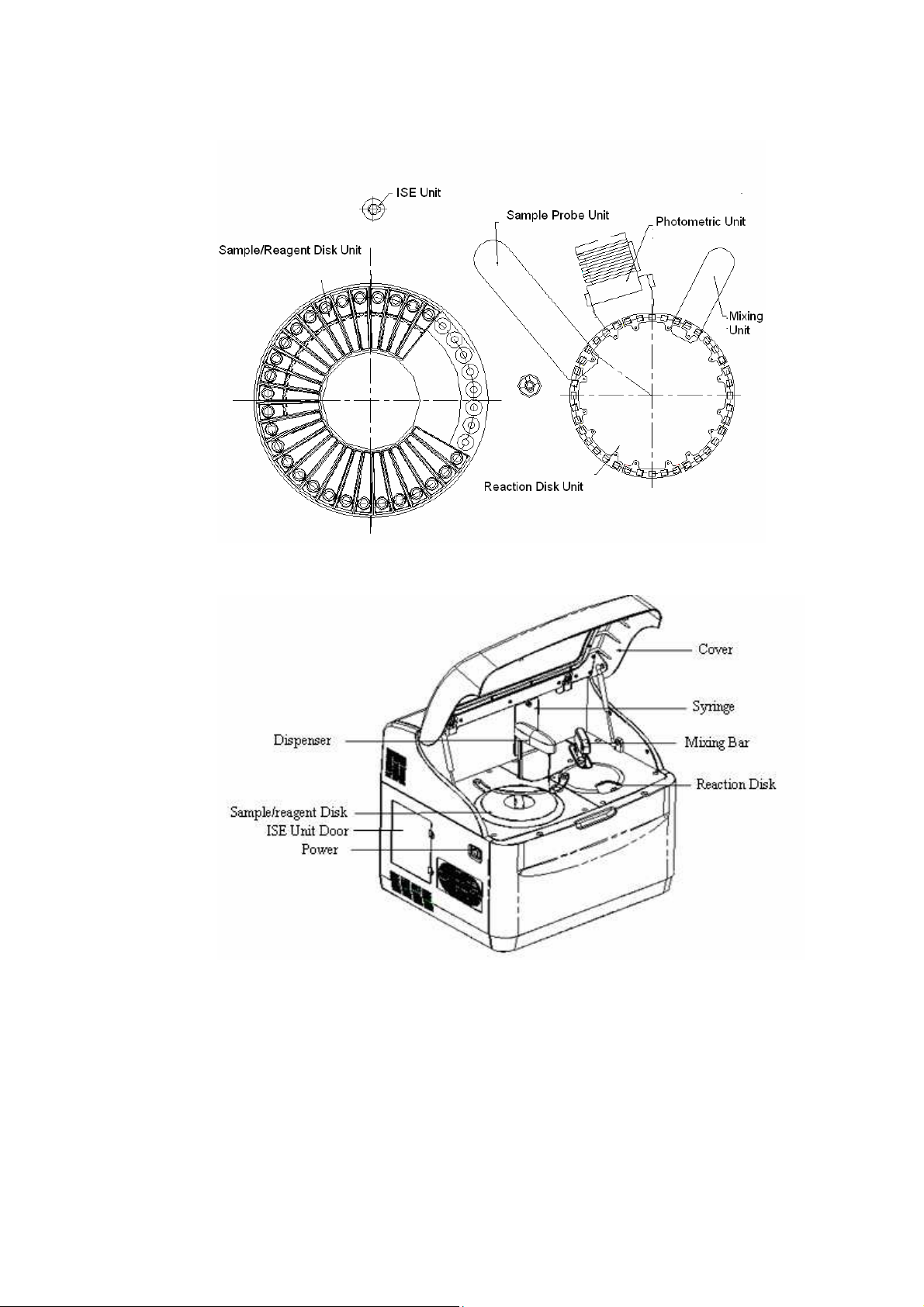
Figure1-1 Layout of the System Panel
Figure 1-2 System Structure-Front View
1 System Description 1-2
Page 24
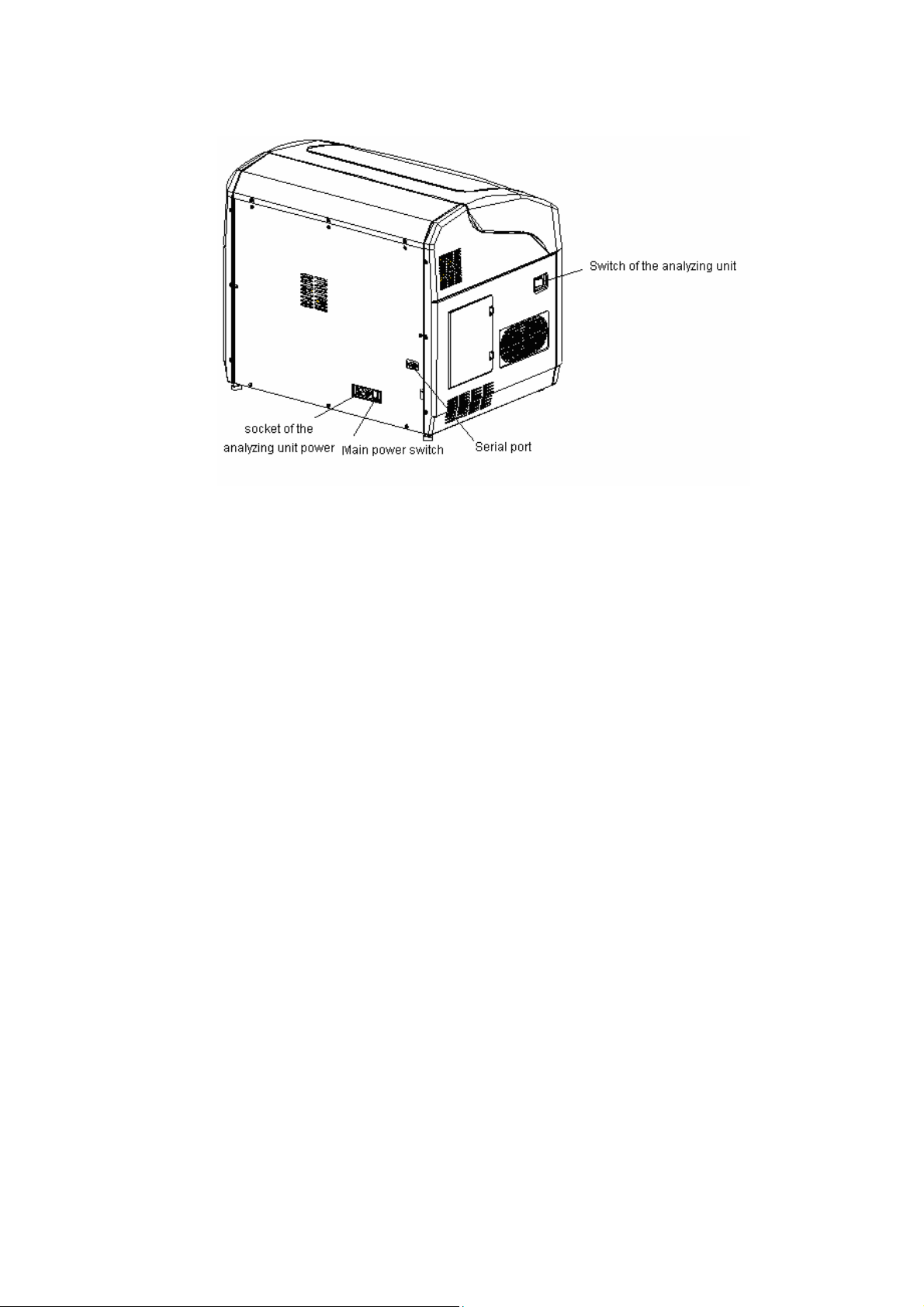
Figure 1-3 System Structure-left Panel View
1.3 Functions
The general working procedure of the BS-120/BS-130/BS-180/BS-190 is as
follows:
1. All mechanical units are initialized.
2. The sample/reagent disk rotates to R1 aspirating position, and the probe
aspirates reagent from a bottle on the sample/reagent disk.
3. The reaction disk carries the cuvettes to the sample/reagent dispensing
position, and the probe dispenses reagent to a cuvette.
4. R1 is incubated in reaction cuvette for several periods.
5. The sample/reagent disk rotates to sample aspirating position, and the
reaction disk carries the cuvettes to the sample/reagent dispensing
position, then the probe dispenses the sample in the reaction cuvette.
6. With sample dispensed, the reaction cuvette rotates to mixing position for
stirring.
7. In case of single-reagent tests, the reaction begins. When defined time is
over, the reaction ends.
8. In case of double-reagent tests, when sample is dispensed and sirred, the
sample/reagent disk rotates to the R2 aspirating position, and the probe
aspirates reagent from the specified bottle on the reagent disk.
9. The reaction disk carries the cuvettes to the sample/reagent dispensing
position, and the probe dispenses reagent to a cuvette.
10. With R2 dispensed, the reaction cuvette is carried to the mixing position
for stirring.
11. During the first and second rotation of each period, the reaction cuvette
receives photometric measurement.
1 System Description 1-3
Page 25

12.
When a batch of analysis is finished or all the cuvettes are used up,
replace the cuvettes manually.
Table 1-1 Functions of System Units
UNIT NAME DESCRIPTION
Sample probe unit
Sample/Reagent
Disk Unit
Reaction Disk Unit
Mixing Unit
Photometric Unit
ISE Unit (optional)
Aspirates and dispenses samples and reagents for all
chemical and ISE tests.
36 positions.
Default: 1~8# sample position; 9~36# reagent position.
Able to hold 40 cuvettes. It provides an environment in
which sample reacts with reagents.
Used to stir the mixture in reaction cuvette when
sample or R2 is dispensed.
Adopts filter wheel structure and performs photometric
measurement (absorbance reading) at 8 wavelengths.
ISE (Ion Selective Electrode) module (not installed on
domestic product).
1 System Description 1-4
Page 26

2
System Performace and
2.1 Technical Specifications
2.1.1 System Specifications
System
Random, multi-channel, multi-test
Sample type
Serum, urine, plasma and CSF (Cerebrospinal fluid)
Number of simultaneous measurements
Workflow
13/26 single-/double-reagent tests
Throughput
BS-120/BS-130: 100 tests/hour, or 300 tests/hour with ISE unit.
BS-180/BS-190: 220 tests/hour, or 440 tests/hour with ISE unit.
Reaction types
Endpoint, Kinetic, Fixed-time; single-/double-reagent test;
single-/double-wavelength test
Reaction time
Maximum 10 minutes for single-reagent analysis; maximum 5 minutes for
double-reagent analysis.
2 System Performance and Workflow
2-1
Page 27

Reaction liquid volume
BS-120/BS-130: 180-500µl
BS-180/BS-190: 150-500µl
Reaction temperature
37℃
Test scope
Clinical chemistries, immunoassays, TDM (Treatment Drug Monitoring)
Auto dilution
Dilution ratio 4~150; dilution is done in reaction cuvette.
Operation mode
System and tests are configured via the operating software. Profiles and
calculation tests are allowed.
Calibration method
Linear (one-point, two-point and multi-point), Logit-Log 4p, Logit-Log 5p, Spline,
Exponential, Polynomial and Parabola
Programming Controls
Westgard Multi-rule, Cumulative sum check, Twin plot
Data processing
Capable of storing and outputting various data and tables/graphs, and calculating
among different tests
Dimensions
l×b×h:690 mm×570 mm×595 mm.
Weight
≤75kg
Emergent samples
Emergent samples can be inserted during test at any time.
Network connection
Able to be connected with LIS (Laboratory Information Management System)
2.1.2 Specifications for Sample System
Sample tube type
Microtube: Φ10×37mm, Φ12×37mm;
Blood collecting tube: Φ12×68.5mm, Φ12×99, Φ12.7×75, Φ12.7×100, Φ13×75,
Φ13×100;
2-2
2 System Performance and Workflow
Page 28

Plastic tube: Φ12×68.5mm, Φ12×99, Φ12.7×75, Φ12.7×100, Φ13×75,
Φ13×100.
Minimum sample volume
Minimum sample volume=dead volume of the sample+total sample volume
needed for all the tests
Dead volume of the sample: Microtube ≤300, Blood collecting tube≤500ul, Plastic
tube≤500ul.
Sample position
Sample and reagent share one sample/reagent disk which is of single-circle
structure. No.1-No.8 are sample positions which can be set as routine, QC, STAT
positions.
STAT sample
Emergent samples can be inserted during test at any time and then run with high
priority.
Sample volume
3µl-45µl, with increment of 0.5µl
Sample probe
Sample and reagent share one probe, which is capable of detecting liquid level,
protecting the probe against collision in the vertical direction and tracking liquid
level.
Sample probe washing
Inside and outside of the probe are washed with carryover less than 0.1%.
Sample input mode
Enter manually
When hand-held bar code system is installed, the sample information can be
entered by using the bar code. Refer to the documents accompanying the
optional hand-held bar code reader.
2.1.3 Specifications for Reagent System
Reagent refrigeration
24 hours non-stop refrigeration, refrigeration temperature: 4-15℃
Reagent dispensing
Reagent is aspirated and dispensed precisely by syringes.
Reagent types
1 to 2 reagent types, R1 and R2
2 System Performance and Workflow
2-3
Page 29

Reagent volume
30µl-450µl, with increment of 1µl
Reagent position assignment
Sample and reagent share one sample/reagent disk which is of single-circle
structure. No.9-No.36 are reagent positions and No. 35 is fixed for wash solution
and No. 36 is fixed for dilution.Other positions can be assigned for R1 or R2. If
ISE module is installed, No.34 is fixed for ISE wash solution.
Reagent input mode
Enter manually
When hand-held bar code system is installed, the reagent information can be
entered using the bar code. Refer to the documents accompanying the optional
hand-held bar code reader.
Reagent probe
Sample and reagent share one probe, which is capable of detecting liquid level,
protecting the probe against collision in the vertical direction and tracking liquid
level.
Reagent probe washing
Inside and outside of the probe are washed with carryover less than 0.1%.
2.1.4 Specifications of Reaction System
Optical path of reaction cuvette
5mm
Material of reaction cuvette
5mm×6mm×30mm, disposable reaction cuvette
Number of reaction cuvettes
40
Mixing method
One mixing bar, which starts to stir after adding a samples or R2
Photometric System
Filter wheel optical system
2-4
Wavelength
8 wavelengths:340nm、405nm、450nm、510nm、546nm、578nm、630nm、
670nm
Wavelength accuracy
±2nm
2 System Performance and Workflow
Page 30

5
Light source
12V, tungsten-halogen lamp, 20W
Photometric measurement method
Photodiode
Measurement range
0~3.5A(for 10mm optical path)
2.1.5 Specifications of Operation
Display
17/15’’ LCD and CRT, resolution: 1024×768, refresh rate: 70Hz
Operating System
Windows XP, Windows Vista
Communication interface
RS-232
Printer
Ink jet printer, laser printer (black-white) and stylus printer
Input device
Keyboard, hand-held barcode scanner connected to the network (optional)
Output device
Display, printer and LIS host
Storage device
Hard disk, USB port
2.1.6 Installation Requirements
Power requirement
100V-130V, 200V-240V
Power frequency
50/60Hz (±3Hz fluctuation)
Power of analyzing unit
350VA
Water consumption
Less than 2.5L/hour
2 System Performance and Workflow
2-
Page 31

6
Environment
Storage temperature: 0~40℃
Storage humidity: 30%RH-85%RH, without condensation
Above-sea-level height (storage): -400~5500 meters
Operating temperature: 15~30℃
Operating humidity: 35%RH-85%RH, without condensation
Above-sea-level height (operation): -400~2000 meters
2.1.7 Optional Modules
ISE (Ion Selective Electrode) module
Hand-held barcode reader
2.2 Workflow (BS-120/BS-130)
2.2.1 Overview
Figure 2-1 General Test Procedure of the BS-120/BS-130
2.2.2 Timing
2.2.2.1 Timing for Main Components
The working period of BS-120/BS-130 is 36 seconds, so its throughput is 100
tests/hour (3600/36). During each working period, the reaction disk rotates three
times and stops three times. During each stop, the sample probe can dispense
sample, first reagent and second reagent respectively. Therefore, the throughput
is not affected no matter it is single-reagent test or double-reagent test because
both of them have the same test efficiency. The practical throughput is affected
by reaction time and cuvettes replacement.
The system collects photometric data two times during each period. Therefore,
the interval between two absorbance readings is 18 seconds for each test.
The movements of major moving parts are shown in the following table.
2-
2 System Performance and Workflow
Page 32

7
finish
Table 2-1 Timing of Major Moving Parts
Components Expected actions
Rotating continuously to
finish photometric
Reaction disk Stop
Sample probe
Mixing bar Mixing R2 Washing mixing bar Mixing S Washing mixing bar Stop Stop
Photometric
system
Aspirating and
dispensing S
Filter wheel rotating
slowly, not
performing
photometric
measurement
measuring of all the
cuvettes and stopping
at the R1 dispensing
position
Washing sample probe
and aspirating R1
Filter wheel stops each
filter on the measuring
position in turn to
photometric measuring
Stop
Dispensing R1
Filter wheel rotating
slowly, not
performing
photometric
measurement
Rotating continuously to
finish photometric
measuring of all the
cuvettes and stopping
at the R2 dispensing
position
Washing sample probe
and aspirating R2
Filter wheel stops each
filter in the measuring
position in turn to finish
photometric measuring
Stop
Dispensing R2
Filter wheel rotating
slowly, not
performing
photometric
measurement
rotating and
stopping after
passing 9 cuvettes
Washing sample
probe
Filter wheel rotating
slowly, not
performing
photometric
measurement
2 System Performance and Workflow 2-
Page 33

8
2.2.2.2 Timing for Sample Probe
a. Lifting up from the wash pool
b. Rotating to the position above the sample/reagent disk
c. Lowering down to the sample tube
d. Aspirating sample and dispensing back a little
e. Lifting up from the sample tube
f. Rotating to the position above the reaction disk
g. Lowering down to the reaction cuvette
h. Dispensing the sample
i. Lifting up from the reaction cuvette
j. Rotating to the position above the wash pool
k. Lowering down to the wash pool
l. Washing inside and outside of the sample probe
2.2.2.3 Timing for Reagent Probe
The timing of dispensing R1 and R2 are basically the same, with slight difference
in the reagent dispensed.Therefore, only the timing of dispensing R1 is shown in
the following:
a. Lifting up from the wash pool
b. Rotating to the position above the sample/reagent disk
c. Lowering down to the reagent bottle
d. Aspirating R1
e. Lifting up from the reagent bottle
f. Rotating to the position above reaction disk
g. Lowering down to the reaction cuvette
h. Dispensing R1
i. Lifting up from the reaction cuvette
j. Rotating to the position above the wash pool
k. Lowering down to the wash pool
l. Washing inside and outside of the reagent probe
2.2.2.4 Timing for Mixing Bar
a. Lifting up from the wash pool and moving into the reaction cuvette
2-
2 System Performance and Workflow
Page 34

b. Sirring reaction liquid
c. Lifting up from the reaction cuvette and moving into the wash pool
d. Washing mixing bar
2.2.2.5 Timing for Reaction Disk
The reaction disk can hold 40 reaction cuvettes. In each working period, the
reaction disk rotates clockwise. It rotates and stops for 3 times respectively, and
passes 41 cuvettes(9+23+9), which means the reaction disk finally stops at the
next position clockwise.
Figure 2-2 Timing of Reaction Disk
2.2.3 Test Workflow
A complete test work flow is show in the following figure.
2 System Performance and Workflow
2-9
Page 35

9
cuvettes
rotating N circles
+9 cuvettes to
Figure 2-3 Workflow for Single-/Double-reagent Tests
finish the photoelectric collection and
stopping the reaction disk at R1 dispensing
Reaction
disk
Period
N=1 R1 33#cuvette
……
N=7
N=8
N=9
N=10
N=11
N=12
N=13
N=14
N=15
N=16
N=17
N=18
N=19
N=20
N=21
N=22
N=23
N=24
N=25
N=26
N=27
Stop
MIX R2
Double-reagent
reaction starts
position)
RB2
……
RB12
RB14
RB16
P2
P4
P6
P8
P10
P12
P14
P16
P18
P20
P22 P23
P24
P28
P30
P32
P34
23 cuvettes (rotating N circles +23 cuvettes to
finish the photoelectric collection and stopping
the reaction disk at R2 dispensing position)
RB1
RB3
RB13
……
MIX SS
Single-reagent
reaction starts
P29
P31
P33
P35
RB15
RB17
P13
P15
P17
P19
P21
P25
P27P26
End
……
P11
9 cuvettes
StopStop
P1
P3
P5
P7
P9
R2
Stop
Position
34#cuvetteN=2
……
39#cuvette
40#cuvette
1#cuvette
2#cuvette
3#cuvette
4#cuvette
5#cuvette
6#cuvette
7#cuvette
8#cuvette
9#cuvette
10#cuvette
11#cuvette
12#cuvette
13#cuvette
14#cuvette
15#cuvette
16#cuvette
17#cuvette
18#cuvette
19#cuvette
36.0
In the figure above, RB1-RB17 are the 17 reagent blank points measured after
R1 is dispensed and before S is dispensed.P1-P35 are the 35 measuring points
after sample is dispensed and mixed to the time when the test with the longest
reaction time is finished.The measuring point, at which sample is dispensed but
not mixed, is invalid and not used in calculation.
2-10
2 System Performance and Workflow
Page 36

2.2.4 Measuring Points
Figure 2-4 Measuring Points for Single-reagent Tests
Figure 2-5 Measuring Points for Double-reagent Tests
2.3 Workflow (BS-180/BS-190)
2.3.1 Overview
Figure 2-6 General Test Procedure of the BS-180/BS-190
2 System Performance and Workflow
2-11
Page 37

2.3.2 Timing
2.3.2.1 Timing for Main Components
The working period of BS-180/BS-190 is 16 seconds, so its throughput is 225
tests/hour (3600/16). During each working period, the reaction disk rotates two
times and stops two times. During each stop, the sample probe dispenses R1
and sample and stirs the sample, and dispensing R2 is done in a single period.
Therefore, the throughput is affected by single or double reagent tests. The
practical throughput is affected by reaction time and cuvettes replacement.
The system collects photometric data two times during each period. Therefore,
the interval between two absorbance readings is 16 seconds for each test.
The movements of major moving parts are shown in the following table.
2.3.2.2 Timing for Sample Probe
a. Lifting up from the wash pool
b. Rotating to the position above the sample/reagent disk
c. Lowering down to the sample tube
d. Aspirating sample and dispensing back a little
e. Lifting up from the sample tube
f. Rotating to the position above the reaction disk
g. Lowering down to the reaction cuvette
h. Dispensing the sample
i. Lifting up from the reaction cuvette
j. Rotating to the position above the wash pool
k. Lowering down to the wash pool
l. Washing inside and outside of the sample probe
2-8
2 System Performance and Workflow
Page 38

2.3.2.3 Timing for Reagent Probe
The timing of dispensing R1 and R2 are basically the same, with slight difference
in the reagent dispensed.Therefore, only the timing of dispensing R1 is shown in
the following:
a. Lifting up from the wash pool
b. Rotating to the position above the sample/reagent disk
c. Lowering down to the reagent bottle
d. Aspirating R1
e. Lifting up from the reagent bottle
f. Rotating to the position above reaction disk
g. Lowering down to the reaction cuvette
h. Dispensing R1
i. Lifting up from the reaction cuvette
j. Rotating to the position above the wash pool
k. Lowering down to the wash pool
l. Washing inside and outside of the reagent probe
2.3.2.4 Timing for Mixing Bar
a. Lifting up from the wash pool and moving into the reaction cuvette
b. Sirring reaction liquid
c. Lifting up from the reaction cuvette and moving into the wash pool
d. Washing mixing bar
2.3.2.5 Timing for Reaction Disk
The reaction disk can hold 40 reaction cuvettes. In each working period, the
reaction disk rotates clockwise. In a routine period, the reaction disk rotates and
stops at the sample dispensing position, and then rotates for 9 cuvette positions
and stops for stirring and R1 dispensing.
2.3.3 Test Workflow
A complete test work flow is show in the following figure.
2 System Performance and Workflow
2-9
Page 39

9
cuvettes
rotating N circles
+9 cuvettes to
Figure 2-7 Workflow for Single-/Double-reagent Tests
finish the photoelectric collection and
stopping the reaction disk at R1 dispensing
Reaction
disk
Period
N=1 R1 33#cuvette
……
N=7
N=8
N=9
N=10
N=11
N=12
N=13
N=14
N=15
N=16
N=17
N=18
N=19
N=20
N=21
N=22
N=23
N=24
N=25
N=26
N=27
Stop
MIX R2
Double-reagent
reaction starts
position)
RB2
……
RB12
RB14
RB16
P2
P4
P6
P8
P10
P12
P14
P16
P18
P20
P22 P23
P24
P28
P30
P32
P34
23 cuvettes (rotating N circles +23 cuvettes to
finish the photoelectric collection and stopping
the reaction disk at R2 dispensing position)
RB1
RB3
RB13
……
MIX SS
Single-reagent
reaction starts
P29
P31
P33
P35
RB15
RB17
P13
P15
P17
P19
P21
P25
P27P26
End
……
P11
9 cuvettes
StopStop
P1
P3
P5
P7
P9
R2
Stop
Position
34#cuvetteN=2
……
39#cuvette
40#cuvette
1#cuvette
2#cuvette
3#cuvette
4#cuvette
5#cuvette
6#cuvette
7#cuvette
8#cuvette
9#cuvette
10#cuvette
11#cuvette
12#cuvette
13#cuvette
14#cuvette
15#cuvette
16#cuvette
17#cuvette
18#cuvette
19#cuvette
36.0
In the figure above, P1a and P1b are collected at different wavelengths in the same
period.
2-10
2 System Performance and Workflow
Page 40

3
Installation
3.1 Environmental Requirements
The system is for indoor use only.
The bearing platform should be leveled with gradient less than 1/200.
The bearing platform should be able to bear 75Kg weight.
The bearing platform should be 500mm-800mm high.
The installation site should be well ventilated.
CAUTION
The system radiates heat when running. A well-ventilated
environment helps keeping the room temperature stable. Use
ventilation equipment if necessary. Do not expose the system to
direct draft that may lead to unreliable results.
The installation site should be free of dust as much as possible.
The installation site should not be under the direct sun.
The installation site should not be close to a heat or draft source.
The installation site should be free of corrosive gas and flammable gas.
The bearing platform should be free of vibration.
The installation site should not be disturbed by large noise or power supply.
The system should not be placed near brush-type motors and electrical
contacts that are frequently powered on and off.
3 Installation 3-1
Page 41

Do not use devices such as mobile phones or radio transmitters near the
system. Electromagnetic waves generated by those devices may interfere
with operation of the system.
The altitude height of the installation site should be lower than 2000 meters.
Ambient temperature: 15℃-30℃, with fluctuation less than ±2℃/H.
Relative humidity: 35%RH-85%RH, without condensation
CAUTION
Operating the system in an environment other than the specified
may lead to unreliable test results.
If the temperature or relative humidity does not meet the
requirements mentioned above, be sure to use air-conditioning
equipment.
3.2 Installation Requirements
3.2.1 Space and Accessibility Requirements
Figure 3-1 Space and Accessibility Requirements
3.2.2 Power Requirements
Power supply: 100-130V/200-240V, 50/60Hz, three-wire power cord and
properly grounded.
The system should be connected to a properly grounded power socket.
3 Installation 3-2
Page 42

The distance between the power socket and the system should be less than
3 meters.
WARNING
Make sure the power socket is grounded correctly. Improper
grounding may lead to electric shock and/or equipment damage.
Be sure to connect the system to a power socket that meets the
requirements mentioned above and has a proper fuse installed.
3.2.3 Water Supply and Drainage Requirements
The supplied water must meet requirements of the CAP Type II water, with
specific resistance no less than 0.5(MΩ.cm@25℃).
The water temperature should be within 5℃-32℃.
BIOHAZARD
Dispose of waste liquids according to your local regulations.
CAUTION
The supplied water must meet requirements of the CAP Type II
water; otherwise insufficiently-purified water may result in
misleading measurement.
3.3 Installation Procedures
3.3.1 Unpacking
Check the delivery list before unpacking. Besides PC and printer box, there
are three boxes for analyzing unit, accessory and deionized water tank,
waste tank and used-cuvette bucket.
The gross weight of the analyzing unit is about 95Kg. 3-4 people are needed
to lay the wooden case containing the analyzing unit on the gound. Use fork
truck, if possible.
Use special tools to unpack the top cover and the side plate.
3 Installation 3-3
Page 43

Figure 3-2 Unpack the Top Cover of the Wooden Case
Figure 3-3 Remove the side plate of the wooden case
Prize the fixing parts around
the top cover, then remove
the top cover.
Prize the fixing parts around
the side plate, then remove
all the side plates
Remove the plastic bag, and use the adjustable wrench to remove the four
plates fixing the feet.
3 Installation 3-4
Page 44

5
Figure 3-4 Remove the Fixing Plate
3.3.2 Installation
Remove the
package
plates of the
front and back
feet.
Fix the analyzer: after the analyzer is placed on the target installation site,
adjust the two front fixing bolts to ensure the four of them have the same
height (the two behind are not adjustable).
Remove the plastic cover and fixing bandage, and install the sample probe
and mixing bar. Do not install the arm cover of the sample probe before
calibrating the level detection board.
• Place the ANALYZING UNIT POWER to ON while ensuring that the sample
probe is not attaching any conducting .object, such as hands.
• Calibrate the sample probe manually. Check if indicator D2 (yellow) is
lightened within 2 seconds when the ANALYZING UNIT POWER to ON. Press
the switch S2 on the level detection board and then release it, then check if
indicator D2 is first extinguished and then lightened. If it is, that means the
calibration succeeds.
Exercise caution to prevent the sample probe from attaching any conducting
object during the calibration.
• Place the ANALYZING UNIT POWER to OFF.
NOTE::::
Remember to install the washer when installing the sample probe.
Use syringe to inject water into the filter and connect the filter to the cap assembly of
the DI water tank. Connect the liquid tubes as indicated in the following figure.
3 Installation 3-
Page 45

6
Figure 3-5 the liquid tubes connecting
CAUTION
Install ISE module(optional):Please refer to 4.8.3 Installing and Removing ISE
Unit.
When placing the deionized water tank and waste tank, ensure the
height difference between the top of the tank and the bottom of the
upper cabinet is within 500-800mm.
Ensure the deionized water pickup tube and waste tank tube are not
blocked, bent, or twisted.
CAUTION
When ISE module electrodes are installed, the power of ISE
module should always be turned on. If the power has been turned
off for more than 0.5 hour, please follow the instructions
demonstrated in the section 7.7.4 Storage of ISE Module.
3 Installation 3-
Page 46

3.3.3 Operating Software Installation
Installation preparation
Configuration:
Operating System: Windows XP Home, Windows Vista Business.
Memory: above 1G;
Graphic Card: above 16 colors;
Resolution: 1024*768
Installation procedure: (Take BS-120 as an example)
1)Double-click the Setup.exe file to start the installation. Select the installation
language.
2)Click Next.
3)Click Change… to modify the installation directory or click Next to enter the next
screen.
3 Installation 3-7
Page 47

4)Click Back to return to the last step to modify the previous setup. Click Install to
start the installation.
5) Click Finish to complete the installation.
3 Installation 3-8
Page 48

3.3.4 Run Operating Software
Turn on Main Power and the Power.
Turn on the printer.
Make sure the liquid tubes are well connected and there is enough deionized water
in the deionized water tank and enough space in the waste tank.
After logging on the Windows operating system, double-click the shortcut icon of the
operating software on the desktop or select the BS-120/BS-130/BS-180/BS-190
operating software program from [Start] to start up the
BS-120/BS-130/BS-180/BS-190 operating software.
After start-up, the analyzer will automatically conduct the following procedures:
checking the operating system and the screen resolution, closing the screen saver,
checking the color configuration, initializing the database and examining the printer.
NOTE
The screen resolution must be 1024x768. The color
configuration must be at least 8 bits.
If all checkings are passed, the following dialog box is displayed. Enter the
username and password, and then click OK. For service personnels, log in with the
maintenance username. Username: bs120, Password: Bs120@Mindray!.
NOTE
While entering the username and the password, pay attention to
the letter case. Capital letters and small letters are different.
The username and password are for service personnels. Do not
release them to customers. Users can only use Admin or other
usernames set by Admin users to log in.
3 Installation 3-9
Page 49

10
Figure 3-6 User Log-in Dialog Box
Enter the username and password, and then click OK to initialize the system and
then operate according to the prompting screen until the main screen of the
operating software is displayed.
After that, wait about 20 minutes until the light source is stable and the reaction disk
temperature reaches 37℃, then the tests can be run. When the lamp is stable, enter
the Maitenance screen and click . Operate as the software instructs to complete
refreshing of the lamp background.
3.3.5 Setting up the System
Before requesting tests, perform the following steps to finish the settings:
To set the options regarding the basic parameters of the system, click Setup
System.
To set the options regarding the hospital and doctor information, click Setup
Hospital.
To set the options regarding parameters of calibrators, click Calibration
Calibrator.
To set the options regarding parameters of controls, click QC Control.
To set the options regarding test parameters, reference, calibration rule and
quality control (QC) rule, click Parameter Test.
To set the options regarding the reagent parameters, click Reagent.
To set the options regarding the carryover information among tests, click
Parameter Carryover.
To set the options regarding the printing parameters, click Setup Print.
The Test screen is where you can set test parameters, reference ranges,
calibration and QC rules of tests.The Test screen includes the following tabs:
Parameters, Reference, Calibration, QC. The Parameters will be explained in
the following figure.
3 Installation 3-
Page 50

Figure 3-7 Parameters Screen
The following table explains the parameters on the Parameters screen.
NOTE
Please set parameters according to instructions of reagents.
Improper settings may lead to unreliable test results.
Parameter Description
Test Name of the test.
No. No. of the test. It cannot be edited.
Full Name Full name of the test. It can be void.
Standard No. Standard No. of the test. It can be void.
Reac. Type Analyzing method, including Endpoint, Fixed-time and
Kinetic.
Pri. Wave. Primary wavelength to be used on the test.
Sec. Wave. Secondary wavelength to be used on the test. It can be void.
Direction It refers to the changing direction of the absorbance during
the reaction process. If the absorbance increases, select
Increase; otherwise, select Decrease.
3 Installation 3-11
Page 51

Parameter Description
Reac. Time The unit is the interval of collecting photometric data, which
equals to 18 seconds for BS-120/BS-130 and 16.3 seconds
for BS-180/BS-190.
The first edit box is start time, and the second one is end
time.
For the Endpoint method, the reaction time refers to the
interval between the start of the reaction and the end of the
reaction.
For the Kinetic or Fixed-time method, the reaction time refers
to the interval between the point when the reaction becomes
stabilized and the point when the reaction is no longer
monitored.
If the reaction time is negative, it means that you should
deduct the reagent blank or sample blank.
For the single-reagent test, the analyzer defines the
photometric data collection point as 0 exactly before the
sample has been dispensed, that is, “0” means the reagent
blank point. The value must not be negative
For the double-reagent test, the analyzer defines the
photometric data collection point as 0 exactly after the
second reagent has been dispensed. The value can be
negative.
Incuba. Time The system assigns the incubation time as 5 minutes.
Unit Unit of the result.
Precision Precision of the result.
R1 It refers to the volume of the first reagent to be dispensed for
the reaction. Increment is 1.
BS-120/BS-130: 180-450µl
BS-180/BS-190: 150-450µl
R2 It refers to the volume of the second reagent to be dispensed
for the reaction. Increment is 1.
BS-120/BS-130: 30-450µ
BS-180/BS-190: 5-450µl
Sample
Volume
It refers to the sample volume (3-45µl) to be dispensed for
the reaction. Increment is 0.5.
NOTE
The sum of the entered R1, Sample Volume
and R2 (as needed) must be as follows:
213µl-500µl for BS-120/BS-130
158µl-500µl for BS-180/BS-190
3 Installation 3-12
Page 52

Parameter Description
R1 Blank It refers to the allowed absorbance range of the R1 blank.
(R1 refers to the reagent of a single-reagent test or the first
reagent of a double-reagent test)
The first edit box is the low limit; the second one is the high
limit. Void means no check.
Mixed Rgt.
Blank
Linearity
Range
Linearity Limit It applies to the Kinetic method only. It ranges from 0 to 1.
Substrate
Limit
Factor For the test with a pre-set calculation factor, you can directly
Prozone
check
It refers to the allowed absorbance range of the mixture of the
double-reagent test.
The first edit box is the low limit, and the second one is the
high limit. Void means no check.
It refers to the range in which the test result is linear with the
response.
The first edit box is the low limit, and the second one is the
high limit. Void means no check.
It refers to the maximum absorbance change relative to the
starting point (the first point when the last reactant is added and
the mixing is done).
It applies to the Kinetic and Fixed-time methods only. It
ranges from 0 to 50,000.
run it without running the calibration first.
Void means the calculation factor is invalid.
Select to check the prozone.
The following parameters are available only when it is
selected.
q1 Prozone test point q1.
It is available when the Prozone check is selected.
q2 Prozone test point q2.
It is available when the Prozone check is selected.
q3 Prozone test point q3.
It is available when the Prozone check is selected.
q4 Prozone test point q4.
It is available when the Prozone check is selected.
PC Prozone limit PC.
It is available when the Prozone check is selected.
Abs Lower limit of prozone absorbance.
It is available when the Prozone check is selected.
3 Installation 3-13
Page 53

3.3.6 Test
Check the photometric system to ensure that it works properly before performing
the tests. Refer to 4.6.4.4 Checking Performance of Photemeter to get the
operation step.
When the instrument is stalled for the first time, execute mechnical resetting for
several times, the liquid path can be primed with wash solution (Maintenance→
Alignment→System).
Before starting the test, be sure to load the conresponding reagent, sample,
calibrator and control to their assigned positions on the sample/reagent disk.
Remember to remove the cap of reagent bottle. If the users set the function of
enhanced wash, the enhanced wash solution must be placed on the No.35 of
sample/reagent disk, and if the users request auto-prediluted test, the distilled
water must be placed on the No.36 of sample/reagent disk so as to use it as
diluent.
NOTE
If the Factor is set, be sure not to set calibration rules at the
Calibration screen. Otherwise, the analyzer will run the calibration
test to obtain calibration parameters rather than calculate them with
the Factor.
Calibration
Run calibration when necessary.
NOTE
You need to run calibration test again when the
measurement conditions such as reagent lot, test
parameters, light source and so on are changed.
To request calibrations, click Calibration Calibration Request.
After requesting calibrations, you should load corresponding calibrators to their
assigned positions on the sample disk.
To run calibrations, click Start.
To view the calibration results, click Calibration Results.
Samples
To request samples, click Sample Request.
Note: STAT samples are requested in the same way as routine ones except that
STAT on the Sample Request screen should be selected when requesting.
After requesting, you should load corresponding samples to their assigned
positions on the sample disk.
To run samples, click Start.
To view the sample results, click Results.
3 Installation 3-14
Page 54

15
QC
To request QCs, click QC Request.
After requesting QCs, you should load corresponding controls to their assigned
positions on the sample disk.
To run QCs, click Start.
To view the QC results, click QC Real-time/ Daily QC / Day to Day QC.
3.3.7 Exit the System
Click Exit to pop up the dialog box, as shown in Figure 3-8. Before exiting, make
sure there is no test running.
Figure 3-8 Confirm Dialog Box
Click OK in Figure 3-8 to exit the operating software and then the dialog box,
as shown in Figure 3-9, will pop up. Operate according to instructions
demonstrated in the following dialog box until exiting the operating software.
Click Cancel in Figure 3-8 to cancel exiting.
Figure 3-9 Shutdown Dialog Box
For service personnels, the emergent exit is available. Click stop in Figure 3-9
and the dialog box will pop up, as shown in Figure 3-10, and then click
Emerg.Exit in Figure 3-10 to exit quickly.
NOTE: The analyzer does not execute any routine exiting procedures when
Emerg.Exit. is chosen. General users should exit the operating software
3 Installation 3-
Page 55

normally, that is, to follow the exiting prompt shown in dialog box to complete
the exiting procedures, including cuvettes replacement, washing, turning off
the light and so on.
Figure 3-10 Emergent Exit Dialog Box
After exiting the operating software, turn off the power of the printer, the
operation unit (personal computer), the display and the analyzing unit
(analyzer) in turn.
The main power of analyzer should be kept on if the reagents are held in the
sample/reagent disk so as to keep cooling the reagents. If the reagents are
taken out to store in other place, the main power could be turned off.
NOTE::::
The refrigerator still functions after the Power is turned off. To shut
down the refrigerator, turn off the Main Power.
3 Installation 3-16
Page 56

4
Units Description
4.1 Enclosure and Panel Unit
The maintenance and replacement of major components or parts need removing
some enclosure and panels. Therefore, the disassembly and installation of the
enclosure and panels are intruduced first.
4.1.1 Components
The outside of analyzer consists of the enclosure and panel unit, which protects the
inner parts of the analyzer and provides dustproof function. The enclosure and panel
unit consists of the protected cover, table panel, left panel, right panel, front panel, top
panel, and rear panel. See Figure 4-1.
4 Units Description
4-1
Page 57

Figure 4-1 Structure of Enclosure and Panel Unit
4.1.2 Dismounting/Mounting of Enclosure Unit
If you need to maintain the inner parts or enclosure parts of analyzer, please turn off
the Power and Main Power, and then carry out the procedures shown in Figure 4-2.
CAUTION
Please turn off the analyzer Power and Main Power before
dismounting or mounting the enclosure and panels.
Figure 4-2 Procedures for Removing Enclosure and Panel Uniit
Usually, do not remove the protected cover because it does not affect the dismounting
of other components. If necessary, please remove one end of the air spring first, and
then remove the fastening screws between the framework and gemel assembly.
The dismounting of rear panel is simple and relatively independent on other panels.
First, unplug the power cable and COM cable on the rear panel, and then dismount the
fastening screws in rear panel. Thus the rear panel can be taken out. For convenient
operation, you can take the flust-type latch in rear panel to remove it. Be sure to pull
out the fan wire plug before removing the rear panel.
4-2
4 Units Description
Page 58

4.1.2.1 Dismounting/Mounting Left /Right Panel
a. Dismount the screws which connect the left panel and the framework. See
Figure 4-3.
b. Move the left panel assembly back until the locating pin and latch hook are
departed from the holes of front panel and framework respectively, and then take
out the left panel assembly.
c. To mount left panel, just reverse the dismounting procedures.
d. The procedures to dismount/mount the right panel are the same as that of left
panel.
Figure 4-3 Removing Left Panel Assembly
4.1.2.2 Dismounting/Mounting Table Panel
CAUTION
While removing and installing the front plate, pay great attention to
the sample probe and the mixing bar to avoid injury resulting from
collision with them. Move the sample probe and mixing bar to the
safe place before operation.
The table panel assembly consists of panel 1, panel 2, and panel 3. See
4-1
.
Dismounting/mounting procedures:
a. Remove the screw caps in table panel.
b. Loosen the screws under the screw caps.
c. Remove the table panel 1, table panel 2 and table panel 3 in turn.
d. Reverse above procedures to mount the table panel.
Figure
4 Units Description
4-3
Page 59

Precautions:
1. Make sure that every gap between two panels is uniform and the sampling and
mixing holes in panel 2 aim at the holes in reaction disk correspondingly.
2. The mounting and dismounting of the table panel should follow the order
mentioned above. That is, when dismounting, the procedure should follow table
1 to panel2 to panel3. Mouting procedure should follow the reverse.
4.1.2.3 Dismounting/Mounting Front Panel Assembly
The procedures are shown as follows.
a. Remove table panel, left panel and right panel.
b. Loosen the fastening screws between the panel assembly and framework
assembly (see
c. When mounting them, reverse steps described above.
Figure 4-4 Removing Front Panel
Figure 4-4
).
4.1.2.4 Dismounting/Mounting Upright Panel and Top Panel
The dismounting/mounting procedures are described as follows.
a. After removing the table panel, loosen all the screws in upright panel and
remove the upright panel. See Figure 4-5.
b. After removing the left panel assembly and right panel assembly, loosen the
three screws on the back of top panel and remove the top panel.
c. To mount them, follow the sequence of top panel, upright panel, left and right
panel.
4-4
4 Units Description
Page 60

5
Figure 4-5 Removing Upright Panel and Top Cover
4.2 Probe Unit
4.2.1 Function Introduction
Probe unit includes the probe, which aspirates sample from the sample tube or
reagent from the reagent bottle and then dispenses the sample or reagent into
reaction cuvette; and also aspirates the sample from the sample tube and then
dispenses it into ISE unit if the analyzer has installed the ISE unit.
The probe also has the function of detecting liquid level, protecting the probe against
collision in the vertical direction and tracking liquid level. What’s more, the probe is
also able to limit its mechanical motion and lock itself when the power failure occurs.
The general workflow of the probe assembly is from wash pool to sample aspirating
position, and then to reaction disk dispensing position and ISE dispensing position.
4.2.2 Components of Probe Unit
The probe unit consists of the probe drive assembly, probe arm assembly, and probe
assembly. See
Figure 4-6
.
4 Units Description
4-
Page 61

6
Figure 4-6 Components of Probe Unit
Probe Drive Assembly: Probe drive assembly supports the probe arm assembly and
drives probe arm assembly to move vertically or horizontally, so the probe can reach
different expected positions. Probe drive assembly includes the horizontal movement
structure and vertical movement structure. Both structures consist of stepping motors,
synchronous belt wheel and synchronous belt. Integrated with a bracket, the two
structures finally drive probe arm assembly to move vertically or horizontally via the
spline shaft.
Probe Arm Assembly: Probe arm assembly is composed of the preheating module,
liquid level detection board, arm cover, etc, which are integrated with the arm base.
Probe Assembly: Probe assembly is fixed to probe arm assembly by the guiding pole
and obstruction spring.
4.2.3 Dismounting/mounting Sample Probe Unit
WARNING
The probe tip is sharp and can cause puncture wounds. Pay great
attention to prevent injury when working around the probe.
WARNING
Wear anti-static gloves or take other protective measures when
removing or touching the circuit board.
BIOHAZARD
Do not touch the probe. If necessary, wear gloves.
4-
4 Units Description
Page 62

7
Figure 4-7 Dismounting of Sample Probe Unit
Arm Cover
Probe Arm
Assembly
M3X10 Screw
Arm Base
Guiding pole
Obstruction
Spring
The Probe
Assembly
M5X20 Screw
Dismounting steps are shown as follows.
a. The probe assembly is fixed to the probe arm assembly by the guiding pole and
obstruction spring. Remove the probe assembly by removing the arm cover, guiding
pole and obstruction spring.
b. The probe arm assembly is fixed to the probe drive assembly with two M3X10
hexagon socket head screws allocated with spring pad. Remove the probe arm
assembly by loosening the two socket screws.
c. The sample probe unit is fixed to base board via three M5X20 hexagon socket head
screws allocated with spring pad. Remove the sample probe unit by loosening the
three socket screws.
Reverse the steps described above to mount the sample probe unit.
Precautions:
1. After installing the probe into guiding pole with obstruction spring, make sure probe
assembly move freely up and down. If not, you should adjust the guiding pole to make it
move freely. Otherwise the function of protecting the probe against collision in the
vertical direction may not work well.
2. Make sure that the probe surface is clean while removing and installing the probe
assembly.
3. Disconnecting correlative power cables, data cables and liquid connecting before
performing the above steps.
4 Units Description
4-
Page 63

8
4.2.3.1 Dismounting/mounting Probe Arm Assembly
Figure 4-8 Probe Arm Assembly
Dismounting steps are shown as follows.
a. The liquid level detection board is fixed to the PCB support via two M3X5 cross pan
head screws. Remove it after removing the arm cover and loosening the two cross
pan head screws.
b. The preheating module is fixed to the arm base via two M3X8 cross pan head
screws. Remove it after removing the arm cover and loosening the two cross pan
head screws.
c. Reverse the steps described above to mount the probe arm seembly.
Precautions:
a. There are two heat insulation plates between the preheating module and the arm
base.
b. The end of the obstruction spring, against which spring wire is pressed tightly,
should be faced down while installing the obstruction spring.
c. Disconnecting correlative power cables, data cables and liquid connecting before
performing the above steps.
4-
4 Units Description
Page 64

4.2.3.2 Probe Drive Assembly
Figure 4-9 Probe Drive Assembly
Dismounting steps are discribed as follows.
A. The horizontal stepping motor is fixed to the motor support with four M3X12 hexagon
socket head screws allocated with plain pad and spring pad. First, remove the
horizontal stepping motor by loosening the four screws, and then take out the horizontal
synchronous belt, and then remove the horizontal synchronous belt wheel which is
fixed to horizontal stepping motor by loosening two M3x5 hexagon socket head set
screws.
B. The vertical stepping motor is fixed to the bracket with three M4X16 hexagon socket
head screws allocated with plain pad and spring pad. First, remove the vertical stepping
motor by loosening the three screws, and then remove the vertical synchronous belt
wheel which is fixed to vertical stepping motor by loosening two M3x5 hexagon socket
head set screws.
C. Remove the dustproof cover by loosening four M3x6 cross pan head screws, and then
remove the press plate by loosening two M3x6 cross countersunk head screws, and
finally take out the vertical synchronous belt.
D. The horizontal senor is fixed to the motor support with one M3X6 hexagon socket head
screw. Remove horizontal sensor by loosening the screw. The vertical sensor is fixed to
the bracket using one M3X6 hexagon socket head screw. Remove vertical sensor by
loosening the screw.
E. The limited position plate which is fixed by three M3X6 cross pan head screws can
adjust horizontal position of the probe arm assembly.
F. Reverse the steps described above to mount the probe drive assembly.
4 Units Description
4-9
Page 65

10
Precautions
1. The synchronous belt wheel which is fixed to stepping motor should keep the same
installation height with the matched belt wheel so that the belt does not bear twisting
force.
2. Use the BA30-K22 fixture to get appropriate tensile force of horizontal synchronous belt
and use the the BA30-K21 fixture to get appropriate tensile force of vertical
synchronous belt.
3. The direction of horizontal and vertical stepping motors’ plug should face outside and
upside respectively.
4.
Disconnect correlative power cables, data cables and liquid connecting before
performing the above steps.
:
4.3 Sample/Reagent Disk Unit
4.3.1 Function Introduction
The sample/reagent disk unit holds the sample tubes and reagent bottles and carries them
to the specified position for aspirating sample or reagent. At the same time it is capable of
refrigerating so as to keep the reagent stable and prevent it from volatilization.
1. Holding sample tubes: Sample containers (tube, microtube, etc) are placed on the
sample/reagent disk unit, and then the sample probe unit aspirates sample and
dispenses them into reaction cuvette.
2. Holding reagent bottles: Reagent bottles are placed on the sample/reagent disk unit,
and then the sample probe unit aspirates reagent and dispenses them into reaction
cuvette.
3. Programmed feeding: The sample/reageng disk unit carries specified sample tubes or
reagent bottles to the aspirating position for aspirating according to the programmed
period. The sample/reagent disk is driven by the drive assembly.
4. Reagent refrigerating: The sample/reagent disk unit is capable of refrigerating and
keeping the reagents at 4-15°C for 24 hours a day so that the reagents are always
stable and not volatilized.
4.3.2 Components of Sample/Reagent Disk Unit
The sample/reagent disk unit consists of reagent refrigerating assembly, disk drive
assembly and disk assembly. See Figure 4-10.
4-
4 Units Description
Page 66

Figure 4-10 Sample/Reagent Disk Unit
Reagent Refrigerating Assembly:The reagent refrigerating assembly is used to
provide refrigeration function and keep the reagents in a low-temperature environment,
so that the reagent are kept stable and will not be volatilized. The reagent refrigerating
assembly consists of refrigeration compartment assembly, refrigeration plate, air duct
and fan assembly.
Disk Drive Assembly: The disk drive assembly can carry specified sample tube or
reagent bottle to the aspirating position for aspirating according to programmed period.
The disk drive assembly consists of drive shaft assembly, sensor assembly, motor
assembly, synchronous belt and coder.
Disk Assembly: Disk assembly is used to hold reagent bottles or sample tubes and
rotates counter-clockwise, carrying each reagent bottle or sample tube to the aspirating
position when needed. The disk assembly includes the handle assembly, reagent disk
assembly and sample disk assembly.
4.3.3 Dismounting Sample/Reagent Disk Unit
CAUTION
The probe tip is sharp and can cause puncture wounds. To prevent
injury, move the probe to the safe position before taking out disk
assembly.
BIOHAZARD
Do not touch the probe and disk assembly. Please wear gloves if
necessary.
4 Units Description
4-11
Page 67

Figure 4-11 Sample/Reagent Disk Unit
A. Pull the handle to vertical direction and take out the disk assembly.
B. Remove the fan assembly by loosening five M4x8 cross pan head screws.
C. Remove the reagent refrigerating assembly by loosening seven M4x8 hexagon
socket head screws.
D. Remove the sensor assembly by loosening three M3x6 hexagon socket head
screws.
E. Remove the motor assembly by loosening four M4x12 hexagon socket head
screws.
F. Mounting the Sample/Reagent Disk Unit follows the reserve steps described as
above
Precautions:
Adjust tensile force of the synchronous belt while mounting the motor assembly.
4-12
4 Units Description
Page 68

4.3.3.1 Reagent Refrigerating Assembly
Figure 4-12 Reagent Refrigerating Assembly
Figure 4-13 Refrigeration Components
The main components of reagent refrigerating assembly that need to be maintained
include refrigerating plate, temperature switch and condensing tube connector. The
steps of discounting are shown as follows.
1. Remove the refrigeration compartment assembly which is fixed to air duct by loosening
four M4x8 hexagon socket head screws.
2. Remove the water-proof glue in the circumference of condensing tube connector and
four M3x12 cross pan head screws. After replacing the condensing tube connector,
4 Units Description
4-13
Page 69

apply some water-proof glue in its circumference when installation.
3. Remove the water-proof glue in the circumference of temperature switch. After replacing
the temperature switch, apply the water-proof glue in its circumference.
4. Remove the water-proof glue in the circumference of radiator, four M4x12 hexagon
socket head screws, radiator and insulation layer in turn, and then replace the
refrigerating plate. You must coat the two sides of the refrigerating plate with
heat-conducting glue (0.1-0.2mm thick) before installing the refrigerating plate; the side
with word is matched with protruding flat. Apply some water-proof glue in the
circumference of radiator after finishing installation.
Precautions
1. Proper screws should be used. Stainless screws are required.
2. The insulation layer should be replaced with a new one while maintaining the
refrigerating plate.
3. The refrigerating plate should be installed in the correct direction (the side with words
should be matched with protruding flat), otherwise it can not function as expected.
4. To install the refrigerating plate, the screws must be tightened evenly to avoid the
damage caused by uneven force when mounting the plate
:
4.3.3.2 Disk Drive Assembly
Figure4-14 Disk Drive Assembly
The disk drive assembly includes the motor assembly, sensor assembly and drive shaft
assembly. The motor assembly and sensor assembly are main parts that need to be
maintained.
4-14
4 Units Description
Page 70

Motor Assembly
Figure4-15 Motor Assembly
1. Remove the small synchronous belt wheel by loosening two M3x5 hexagon socket
head set screws.
2. The motor is fixed to the motor support plate with four M4X12 hexagon socket
head screws.
Precautions:
1. Apply some screw glue while mounting M3x5 hexagon socket head set screws.
2. The installation height of small synchronous belt wheel should be kept the same
with the matched belt wheel while installing
3. Adjust tensile force while installing the small synchronous belt wheel.
4. The direction of motor plug faces to the side with bended flange of the motor
support plate. See Figure4-15.
Sensor Assembly
CAUTION
Do not dismount the sensor assembly if not necessary. Otherwise
the position of sensor may be changed, which may cause
aspirating position changed.
If the position of sensor assembly is changed, the sample
aspirating position needs to be re-adjusted.
4 Units Description
4-15
Page 71

16
Figure4-16 Sensor Assembly
Remove two M3x6 hexagon socket head screws, and then remove the zero sensor and
coder sensor which are fixed to the sensor bracket.
Precautions:
The positions of zero sensor and coder sensor can not be changed.
4.3.3.3 Disk Assembly
Figure4-17 Sample/Reagent Disk Assembly
Remove the handle assembly which is fixed to reagent disk assembly by loosening four
M4x8 cross pan head screws. The sample disk assembly can be taken out from the
reagent disk assembly directly. The introduction of reagent disk assembly and sample
disk assembly is as follows.
4-
4 Units Description
Page 72

17
Reagent Disk Assembly
Figure 4-18 Reagent Disk Assembly
The reagent bottle holder is fastened on the reagent disk base. The reagent bottle
holder can be pulled out or pushed in the reagent disk base by hand directly.
Precautions: Make sure that the reagent bottle holder is fastened completely on the
reagent disk base.
Sample Disk Assembly
Figure 4-19 Sample Disk Assembly
Remove one M3x8 cross countersunk head screw, and then replace the tube clip which
is fixed to the sample base.
4.4 Reaction Disk Unit
4.4.1 Function Introduction
The reaction disk unit holds reaction cuvettes and rotates clockwise, carrying the
cuvettes to specified position for sample/reagent dispensing and stirring. The reagents
and the sample react in reaction cuvette. Also the reaction disk unit provides a
constant-temperature environment for the reaction.
Figure 4-20
No.2 is aspirating pre-diluted sample position. No.5 is photometric measuring position.
No.10 is stirring position. No.25~No.29 is for replacing the cuvettes manually.
4 Units Description
shows the position on the reaction disk. No.1 is dispensing R1/R2/S position.
4-
Page 73

18
Figure 4-20 Working Positions on Reaction Disk
Diluted Sample
Position(2#)
Dispensing
R1/S/R2
Position(1#)
Photometric
Position(5#)
Replacing the Cuvettes by
Hand Position(25~29#)
Stirring Position
(10#)
4.4.2 Components of Reaction Disk Unit
The reaction disk unit consists of reaction disk movement assembly and reaction
compartment assembly.
Reaction Disk Movement Assembly: It consists of disk assembly and disk drive
assembly. It holds cuvettes and carries them to the expected postion for
Sample/Reagent dispensing or stirring. Also the photometric measurement is carried
out when the reaction disk is rotating. The disk drive assembly includes the coder
sensor assembly, motor assembly and drive shaft assembly.
Coder Sensor Assembly: The function is to find the mechanical zero position and
count the valid edges of the coder.
Motor Assembly: It drives the reaction disk to rotate via the belt and the two belt
wheels.
Reaction Compartment Assembly: It provides a constant-temperature environment
for the reaction and consists of the compartment assembly and up cover assembly.
4-
4 Units Description
Page 74

Figure 4-21 Reaction Disk Unit
4.4.3 Dismounting Reaction Disk Unit
Figure 4-22 Reaction Disk Unit
4 Units Description
4-19
Page 75

The steps are shown as follows.
1. Remove the up cover assembly which is fixed to compartment by loosening four
M4x10 hexagon socket head screws.
2. Remove the disk assembly which is fixed to drive shaft assembly by loosening three
M3x12 hexagon socket head screws.
3. Remove the photometric unit which is fixed to compartment assembly by loosening
three M4x16 hexagon socket head screws.
4. Remove the compartment assembly which is fixed to compartment support pole by
loosening four M5x20 hexagon socket head screws.
5. Remove the coder sensor assembly which is fixed to base board by loosening three
M3x6 hexagon socket head screws.
6. Remove the motor assembly which is fixed to motor support pole by loosening four
M4x12 hexagon socket head screws.
Precautions:
1. Correct direction of plug is required while installing the motor assembly.
2. Proper tensile force is required while installing the synchronous belt.
4.4.3.1 Motor Assembly
The structure and the steps of dismounting motor assembly are similar to the
sample/reagent disk. Please refer to the relative content of Motor Assembly
in chapter 4.3.3.2.
4.4.3.2 Coder Sensor Assembly
The steps of dismounting coder sensor assembly are similar to the sample/reagent disk.
Please refer to the relative content of Sensor Assembly
CAUTION
Do not remove the sensor assembly because the position change
of sensor may cause the photometric measuring position change.
If the position of sensor assembly is changed, the position of
photometric measurement needs to be re-adjusted. For details on
adjusting, please refer to 4.6.4.1.
described
in chapter 4.3.3.2.
described
4-20
4 Units Description
Page 76

4.4.3.3 Compartment Assembly
Figure 4-23 Compartment Assembly
1. Remove the fan support which is fixed to compartment by loosening the two M3x6 pan
head screws.
2. Remove the fan which is fixed to fan support by loosening the two M3x16 hexagon
socket head screws.
3. Remove the temperature sensor by loosening the M2.5x8 hexagon socket set head
screw.
4. Remove the down heating appliance which is fixed to compartment by loosening the
four M4x8 hexagon socket set head screws.
Precautions:
1. Do not tighten the M2.5x8 hexagon socket set head screw too tight when mounting the
temperature sensor.
2. The side of down heating appliance that is in contact with the compartment must be
coated with heat–conducting glue (0.1-0.2mm thick) while installing it.
4 Units Description
4-21
Page 77

4.4.3.4 Cover Assembly
Figure 4-24 Cover Assembly
The temperature protective switch and up-heating appliance are installed between the press
plate and the cover, and they can be removed by loosening four M4x6 hexagon socket head
screws.
Precautions:
1. The side of up-heating appliance that is incontact with the press plate must be coated
with heat –conducting glue (0.1-0.2mm thick), and the up-heating appliance cables are
placed in the groove of the press plate so as to avoid pressure.
2. The temperature protective switch must be coated with heat-conducting glue
(0.1-0.2mm thick), and it should be carefully installed in the specified position while
installing.
4.5 Mixing Unit
4.5.1 Function Introduction
The mixing unit is equipped with a mixing bar, which is used to stir the liquid in cuvettes.
Additionally, the mixing unit has a specified mechanical position and is able to lock itselt
when power failure occurs.
The working position of the mixing bar: the wash well and the stirring position
4.5.2 Components of Mixing Unit
The mixing unit consists of mixing drive assembly and mixing arm assembly.
4-22
4 Units Description
Page 78

Figure 4-25 Mixing Unit
Mixing drive assembly: It supports the mixing arm assembly and drives the arm to do
curvilinear movement in horizontal plane, so that the mixing bar moves between the two
working positions. It consists of stepping motor, shaft, bearing, linear guide way, etc, which
are integrated by the cam board. The arm shaft transfers movement to the mixing arm
assembly.
Mixing arm unit: It consists of a mixing bar, motor, cover, etc. and all of them are integrated
by the arm base.
4.5.3 Dismounting Mixing Unit
BIOHAZARD
Do not touch the mixing bar.Wear gloves, if necessary.
4 Units Description
4-23
Page 79

Figure 4-26 Mixing Unit
1. The mixing arm assembly is fixed on the mixing drive assembly with two M3x10
hexagon socket head screws allocated with plain pad and spring pad. Remove the
mixing arm assembly by loosening the two screws.
2. The mixing unit is fixed on the base board with four M4x102 hexagon socket head
screws allocated with spring pad. Remove the mixer drive assembly by loosening
the two screws.
Precaution:
Remove the cables before performing above steps.
4.5.3.1 Mixing Arm Assembly
BIOHAZARD
Do not touch the mixing bar.Wear gloves when necessarily.
4-24
4 Units Description
Page 80

Figure 4-27 Mixing arm assembly
1. Remove the mixing bar by loosening the nut.
2. The mixing motor is fixed on arm base with two M2x4 cross pan head screws
allocated with plain pad. Remove the mixing motor by removing the cover and the
two screws.
Precautions:
1. Make sure that the end of mixer is in contact with protruding plane of the mixing
motor as close as possible before screwing the nut.
2. Make sure to keep the mixing bar clean while removing and installing it.
3. Remove the cables before performing above steps.
4.5.3.2 Mixer Drive Assembly
Figure 4-28 Mixing drive assembly
1. The motor is fixed on motor support with four M4x10 hexagon socket head screws
allocated with spring pads. Remove the motor by loosening the four screws, and
4 Units Description
4-25
Page 81

then loosen two M4x8 hexagon socket set head screws to remove the lever from
the motor.
2. Remove the motor support which is fixed to cam board by two M4x6 and two M4x8
hexagon socket head screws allocated with spring pads, and then take out the
shaft ring.
3. Remove one M3x8 hexagon socket head screw allocated with spring pad and plain
pad, and then take out the output shaft and cushion.
4. The sensor is fixed to bolt by two M3x6 hexagon socket head screws; remove the
sensor by loosening the two screws.
Precautions:
1. The motor shaft should protrude the plane of lever about 3mm while installing the
lever.
2. Place the plug of stepping motor faced down while installing the stepper motor.
3. Remove the cables before performing above steps.
4.6 Photometric Unit
4.6.1 Introduction
Chemistry analyzer is a typical instrument which features in optics,mechanics, electronics
and arithmetic. The photometer is one of the key components of the instrument and
determines directly the precision and accuracy of measurement of the system.
The light source irradiates directly the cuvette in the photometer. A combined light passes
through an optical interference filter and turns to a monochromatic light. The
monochromatic light passes through the cuvette and is received by the photoelectric
detector and then is converted into an electrical signal by the photoelectric detector. The
microprocessor calculates the concertration of the solution in the cuvette by contrasting
the optical intension of the light before and after passing through the solution. The multiple
monochromatic wavelengths in the pototometer system are obtained by utilizing the filter
wheel. Rotate the filter of a specific wavelength to the light path while performing the
colormetric measurement.
4.6.2 Components of Photometric Unit
The lens 1 converges the light beam emitted from the light source to the filter. The lens 2
collimates the monochromatic light beam aimming to the reaction cuvette. The light is
absorbed when passing through the solluton and then is converged at the photodiode via
the lens 3. Finally the photodiode converts the light signals into electric signals and then
outputs them. From the outside to the inside of the reaction disk, the whole configuration
of the light path is shown in Figure 4-29.
4-26
4 Units Description
Page 82

Figure 4-29 Structure of Photometric Unit
The photometric unit is installed on the reacton disk (see Figure 4-22). It can be divided into
two parts (see Figure 4-30): Light source assembly and Forward optics assembly.
The AD collection board that performs data collection is placed in the AD housing assembly.
The AD housing position on the analyzer is shown in Figure 4-31.
Figure 4-30 Components of Photometric Unit
4 Units Description
4-27
Page 83

Figure 4-31 Position of Photometric Unit and AD Housing Assembly
4.6.2.1 Light Source Assembly
The light source assembly is composed of a filter wheel assembly, a lamp assembly, a light
source seat, lenses, radiators, fans, a motor and a sensor. The main function is to provide a
stable lignt source that emits a light beam to converge to the filter via lens. The filter of a
specific wavelength is placed to the light path by rotating the filter wheel. Also a good cooling
function for the lamp assembly is provided by the light source assembly.
Figure 4-32 Light Source Assembly
4-28
4 Units Description
Page 84

4.6.2.2 Forward Optics Assembly
The forward optics assembly is composed of a pre-amp housing assembly, an optics seat,
lenses, and a retaining nut. The main function is to converge the light beam passing through
the filter at the reaction cuvette, and then to converge the light beam passing through the
cuvette at the photodiode via the lens, and finally to perform the colormetric measurement.
Figure 4-33 Forward Optics Assembly
4.6.2.3 AD Housing Assembly
The AD housing assembly is composed of an AD housing, a shielding box and an AD
conversion board. The founction of the AD housing assembly is to support and shield the AD
conversion board.
Figure 4-34 AD Housing Assembly
4 Units Description
4-29
Page 85

4.6.3 Dismounting and Mounting Photometric Unit
Figure 4-35 Dismounting Photometric Unit
Dismounting steps are as follows.
1. Remove the rear panel of the analyzer and the table panel 1 above the light
source aassembly.
2. Remove the light source assembly: Loosen the three M4X20 socket screws and
unplug the connectors of the lamp wire, the fan wire, the motor wire and the
sensor wire. And then remove the light source assembly.
3. Remove the forward optics assembly: Remove the reaction disk cover and the
reaction disk. Loosen the three M4X16 socket screws and remove the forward
optics assembly.
4. Remove the pre-amp housing assembly: The pre-amp housing assembly is
installed on the forward optics assembly. Unscrew the two M3X16 socket screws
and remove the pre-amp housing assembly.
5. Reserve the steps described above to mounting the photometric unit
6. Dismounting and mounting the AD housing is independent on what to do with the
light source assembly and the forward optics assembly.
Precautions:
1. The light source assembly should be inclined slightly to the reaction disk when
removed together with the dustproof cover. Be careful not to scrape the filter.
2. You can remove the dustproof cover and then remove the light source assembly.
Thus it is easier to operate.
3. The forward optics assembly is connected with the reaction disk by matching the
two pins at the bottom of the optics seat with the two corresponding pin holes in
the reaction disk. It may be tight when taking out the forward optics assembly due
to the firm conjunction.
4. Unplug the connectors of the wire before removing the assemblies and plug the
connectors after installation.
5. Be careful not to scrape the surface of the filter when removing the light source
assembly.
4-30
4 Units Description
Page 86

4.6.3.1 Light Source Assembly
Figure 4-36 Dismounting Light Sourec Assembly
Dismounting steps are as follows:
1. The filter wheel is installed on the motor. Unscrew the M2.5X8 pan head screw and
remove the filter wheel.
2. Loosen the FT3X8 screws to replace the filter in the filter wheel. Refers to Chapter
7.6.3 for details about the filter replacement.
3. Loosen the M3X8 socket screw to repair or replace the sensor.
4. Loosen the two M3X25 socket screws to repair or replace the fan.
5. Loosen the retaining screw to remove or replace the lamp. Refers to Chapter 7.6.2
for details about the filter replacement.
6. Precautions:
1. Gently clean the surface of the filter with ethanol-soaked defatted cotton if it is
contaminated during installation
2. Don’t touch the glass surface of the lamp with hand.
3. Put on the clean white gloves when replacing the filter or the lamp.
4.6.3.2 Forward Optics Assembly
Dismount forward optics assembly is described as follows. (See Figure 4-35)
1. Remove the light source assembly.
2. Remove the reaction disk cover and the reaction disk.
3. Remove the forward optics assembly.
4. Remove the pre-amp housing assembly.
5. Reverse the steps described above to mount the forward optics assembly.
Precautions:
1. Unplug the connectors of the wire before removing the assemblies and plug the
connectors after installing.Don’t touch the glass surface of the lamp.
2. Be careful not to scrape the surface of the filter when removing the light source
assembly..
4 Units Description
4-31
Page 87

4.6.3.3 AD Housing Assembly
Figure 4-37 AD Housing Assembly
1. Remove the three table panels to expose the AD housing assembly.
2. Unscrew the two M3X8 screws allocated with pad and remove the shielding box.
And then repair the AD conversion board.
3. Unscrew the four M3X6 pan head screws and then replace the AD conversion
board.
4.6.4 Adjustment of Photometer
4.6.4.1 Adjusting Photometric Position of Reaction Disk
The photoelectric collecting position in the reaction disk depends on the installing
position of the coder sensor of the reaction disk. Any slight movement of the sensor will
change the photoelectric collecting position and then affect the performance of
photoelectric collection. Therefore, don’t remove the coder sensor unless it is
necessary.
CAUTION
It is necessary to check the photoelectric collecting position after replacing the the
coder sensor or tightening the screw of the sensor bracket,
The adjustment of photometric position is carried out by using an oscillograph to
measure the photoelectric analog signal and the AD collection start signal. The probe
of the oscillograph should be connected to the specified signal test point.
Don’t remove the coder sensor of the reaction disk unless it is
necessary.
The adjusting steps are described as follows.
1. Make sure to turn off the power switch of the analyzing unit.
2. Open three table panels to expose the AD housing assembly. (See Figure 4-37)
4-32
4 Units Description
Page 88

Signal V3
CAUTION
Before opening the table panels, pull up the sample probe and the
mixing bar so as to operate conveniently.
WARNING
Be careful not to be injured by the sample probe.
BIOHAZARD
Don’t touch the the sample probe with naked hand.
3. Open the shielding box of the AD housing assembly(See Chapter 4.6.3.3 ), and
connect two probes of the oscillograph to the AD start signal(RC and GND) and the
analog signal (V3), then connect the earth terminal to the ground.
Figure 4-38 AD Conversion Board
Analog
AD start
signal RC
Earth Terminal
GND
4. Turn on the Main Power.
5. Enter the BS-120/BS-130/BS-180/BS-190 test and maintenance software(See
Chapter 8). Place 40 clean cuvettes on the reaction disk. Click Rotate and
measure to start the photoelectric measurement. In the meantime, start the signal
collection of the oscillograph. The software interface is indicated in Figure 4-39.
4 Units Description
4-33
Page 89

Figure 4-39 Photometric Instruction
6. When the oscillograph displays the complete waves circularly shown in Figure
4-40, press STOP on the oscillograph. The waves are frozen.
Figure 4-40 Photometric Wave
7. Magnify the waves shown above and check whether the AD start signal is in the
middle of the photometric analog signal (See Figure 4-41). If yes, the photometric
position is correct.
4-34
4 Units Description
Page 90

35
Figure 4-41 Photometric Wave Feature
8. If the AD start signal is in the decreasing part of the photomectric analog signal
instead of the middle part, the photomectric position is not proper and must be
adjusted by moving the coder sensor of the reaction disk. If the AD start signal is
on the left, then move the sensor along clockwise. If it is on the right, move the
sensor along counter-clockwise. The left panels, right panels and front panels
should be removed for adjusting the sensor.
10.
Adjust the coder sensor of the reaction disk: the sensor is fixed on the sensor
bracket and only the sensor bracket should be adjusted.See Figure 4-42, loosen
the three screws and adjust the sensor bracket position according to the
photoelectric wave. After completing the photomectric position adjustment, tighten
the three screws.
11.
After finishing the above operation, send Ordinary Rotate&Measure Instruction
and check the photometric waves again.
4 Units Description
4-
Page 91

36
Figure 4-42 Adjusting Coder Sensor of Reaction Disk
Sensor Bracket
4.6.4.2 Adjusting Offset of Filter Wheel
After moving the sensor of the filter wheel or removing the filter wheel, you should
adjust the offset of the filter wheel and set parameters.
Refer to Chapter 8.5.1 for details about adjusting the filter wheel offset.
4.6.4.3 Adjusting Signal Gain of Photometric Unit
The purpose of adjusting signal gain is to ensure that the air blank AD value is within
48000 -60000 after replacing new lamp.
CAUTION
If air blank AD value is lower than usual after replacing new lamp,
check whether the surface of the lamp or the filter is dirty.
Refer to Chapter 8.5.2 for details about adjusting signal gain of the photoelectric unit.
Precaution for signal gain adjustment::::
1. It is not recommended to extend the service life of the lamp by adjusting the signal
gain.
4-
4 Units Description
Page 92

37
2. The signal gain of the photoelectric unit has been configured properly before the
analyzer is sold to the custumer. When an alarm occurs indicating weak light,
replace the lamp directly instead of adjusting the signal gain. Usually it is
unnecessary to adjust signal gain after replacing the lamp. However, after doing
that, you should check whether the air blank AD exceeds the range on the
Maintenance-Daily Maint. page of the operating software. If not, click new lamp to
complete replacing new lamp. If yes, you need to adjust the signal gain.
3. Adjust the signal gain: It is recommended to use both automatic adjustment and
manual adjustment. Adjust signal gain automatically, and then adjust manually.
4.6.4.4 Checking Performance of Photometer
It is recommended to check the performance of photometer under the following
conditions:
1. The analyzer installation is completed.
2. The lamp is replaced or re-installed.
3. The filters are replaced or re-installed.
4. The measurement data is abnormal.
The checking method is as follows.
Request the tests that use water as sample and reagent in operating software.
For replacing or re-installing the lamp, request 20 times replicated tests in which the test
wavelength parameter is set as 340 and 405nm.
For other cases, it is necessary to check performance of each walvlength. So request 5
times replicated tests under each diffirent wavelength respectively (40 tests total).
The test time is set as 0~35 and other parameters are not limited.
Check reaction curve and data of each test after completing all the tests. The difference
between the minimum absorbance value and the maximum value for each detecting
point should be less than 30.
If the results can’t be compliant with the requirement, please check the following details.
If the test data from all wavelengths are abnormal, make sure that the installaion of
lamp is ok, including whether the pottery socket is stable and whether the lamp is
installed in the proper position.
If the test data from a part of wavelengths are abnormal, check whether the filter is
installed in the right way or whether the filter surface is dirty or has nicks
Check whether the lamp intensity is stable.
If the test data from a few cuvettes can’t be compliant with the requirement, it can
be concluded that there is no problem with the photometer and then check whether
there are air bubbles in the cuvette or whether the surface of the cuvette is dirty. If
yes, the photomethic performance is ok and the abnormal data can be ignored.
Check the performance again after resolving all of the above problems. If there are still
abnormal data, please contact the development engineer.
4 Units Description
4-
Page 93

38
4.7 Power Supply Unit
4.7.1 Function and Components
The power supply unit provides the proper power for each module of the analyzer. It consists
of three PCB boards, four fans, power switch and plug receptacle.
The power system includes three circuit boards: 24V board, 12V board and power
connection board.
The 24V board transforms the AC power to the A24V, B24V and A12V the lamp
source).
The 12V board transforms the AC power to other 12V( B12V and C12V) and 5V
required by the system.
The power connection board has the function of relaying the AC power, transforming
the voltage to -12V, controlling the C12V and relaying the output of the other voltages.
The power supply unit provides all power through the joggles on the power connection
board, but the 24V board and the 12V board connect the power connection board
through the board to board plugs.
The power supply unit is an integrated module. It can be shielded and isolated by the
metallic crust.
The heat radiation of the system is implemented via the cooling air provided by fans.
4.7.2 Dismounting Power Supply Unit
The position of power supply unit is shown as Figure 4-43.
Figure 4-43 Position of Power Supply Unit
4-
4 Units Description
Page 94

Figure 4-44 Dismounting Power Supply Unit
The dismounting steps are shown as follows.
1. Remove the rear panel.
2. Unplug all connection cables.
3. Remove the four M4x12 cross pan head screws and then pull out the power
supply module from the framework.
The mouting steps are shown as follows.
1. Push the power supply module into the framework and insert the power box
press under the press plate.
2. Fix the power supply module using four M4x12 cross pan head screws.
3. Install the rear panel.
4. Plug all connection cables.
4.8 ISE Unit (Optional)
4.8.1 Introduction
The ISE module is optional for fully-automated chemistry analyzers and designed to
measure the concentration of K+, Na+, Cl- and Li+ in serum, plasma and diluted urine.
The volume needed for testing is 70µl in the serum or plasma sample and is 140µl in
the diluted urine sample. The dilution ratio of the urine sample is 1:10 (1 part of urine
sample and 9 parts of diluent)
4.8.2 Components of ISE Unit
The ISE unit consists of the ISE module, pump module and reagent module. See Table
4-1 and Figure 4-45.
Table 4-1 Components of ISE Unit
NAME DESCRIPTION
The ISE module includes five electrodes (Li+, Na+, K+,
ISE module
4 Units Description
Cl- and Reference). Samples are dispensed via the
sample entry port on the top of the ISE module and then
measured.
4-39
Page 95

40
Pump module
Reagent module
The pump module includes three peristaltic pumps,
which are used to transfer reagents and waste liquid.
The reagent module includes calibrant A, calibrant B,
waste tank and a chip that indicates the remaining
volume of the reagent. This module provides the function
of the reagents supply and the waste liquid storage.
4.8.3 Installling and Removing ISE Unit
The ISE module, pump module and reagent module are fixed on the base board with
screws. (See Figure 4-45)
Figure 4-45 Components of ISE Unit
4-
4 Units Description
Page 96

4.8.3.1 ISE Module
Figure 4-46 ISE Module
The dismounting/mounting steps are as follows (see Figure 4-46 ).
Dismounting steps:
1. Remove the table panel and the ISE unit door.
2. Unplug the draining tube connected to the ISE module.
3. Loosen the screw and remove the ISE shielding cover.
4. Loosen the four M3X8 cross pan head screws retained on the ISE shield
housing and remove the ISE module.
Mounting steps:
1. Install the ISE module on the ISE shield housing by tightening the four M3X8
cross pan head screws.
2. Install the ISE shielding cover by tightening the screw.
3. Pull out the draining tube through the hole in the ISE shielding cover.(it is not
indicated in figure)
4. Install the table panel and ISE unit door.
4 Units Description
4-41
Page 97

4.8.3.2 Pump Module
Figure 4-47 Pump Module
The dismounting/mounting steps are as follows
Dismounting Steps:
1. Remove the rear panel of the analyzer.
2. Pull out the tube and unplug the connection of the motor. ( not indicated in
figure.)
3. Loosen the four M2.5X6 screws and remove the peristaltic pump. The
installation of the three pumps is indepent to each other.
4. The pump support is fixed on the base board by tightening the four M4X10
socket screws. Remove the pump support if necessary.
Mounting steps:
1. Fix the pump support on the base board by tightening the four M4X10 socket
screws.
2. Install the peristaltic pump on the pump support by tightening the four M2.5X6
cross pan head screws.
3. Connect the tube and plug the connection of the motor.
4. Install the rear panel on the analyzer.
. (See Figure 4-47)
4-42
4 Units Description
Page 98

4.8.3.3 Reagent Module
Figure 4-48 Reagent Module
The reagent module consists of a reagent pack and a reagent pack seat. The reagent
pack seat is fixed on the base board by the three M4X10 socket screws.
Dismounting steps:
1. Remove the ISE unit door on the left side of the analyzer.
2. Pull out the tube of the reagent module.
3. Take out the reagent pack horizontally.
4 Units Description
4-43
Page 99

4.8.3.4 ISE Electrodes
The steps of installing the ISE Electrodes are as follows.
1 Take out the reference electrode from the package and pull out the yellow
intubatton. Pull down the press plate of the ISE module and push the reference
electrode into the ISE module. (Don’t throw away the yellow intubatton and
use it again when storing the electrode.) If white crystalloids adhere to the tube
of the reference electrode, wash it with warm water before installing.
2
Put the other electrodes into the ISE module. It is easier to install the K+, Na+,
Cl- electrodes than the spacer electrode. To insert the spacer electrode (the
top one), it is needed to slightly press the press board.
4-44
Caution: Replace the space electrode with the Li+ electrode when necessary.
4 Units Description
Page 100

45
3
Remove the electrodes following the reverse steps described above. It is important to
execute the procedure such as tubing purge and warm-up before dismounting the
electrodes. Store the electrodes properly after removing them from the instrument. Refer to
Chapter 7.7.4 for more details about removing and storing the electrodes.
Check whether the five electrodes are installed properly.Make sure the
electrodes stand in a line vertically and their front surfaces are lined up.
CAUTION
The ISE unit (optional) should be on power all the time. In some cases the
Power will be shut down for more than half an hour, strore the electrodes
referring to Chapter 7.7.4.
4 Units Description
4-
 Loading...