

Page 1
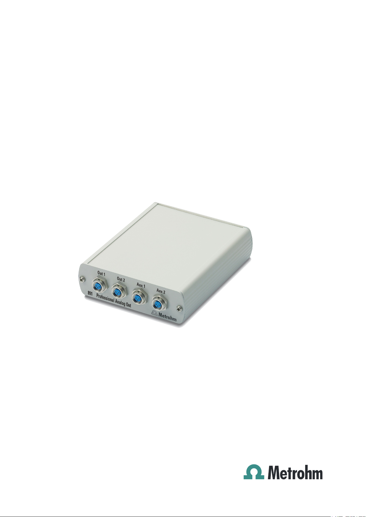
891 Professional Analog Out
2.891.0010
Manual
8.891.8001EN / 2014-03-18
Page 2

Page 3

Metrohm AG
CH-9100 Herisau
Switzerland
Phone +41 71 353 85 85
Fax +41 71 353 89 01
info@metrohm.com
www.metrohm.com
891 Professional Analog Out
2.891.0010
8.891.8001EN / 2014-03-18
Manual
zst
Page 4

Teachware
Metrohm AG
CH-9100 Herisau
teachware@metrohm.com
This documentation is protected by copyright. All rights reserved.
Although all the information given in this documentation has been
checked with great care, errors cannot be entirely excluded. Should you
notice any mistakes please send us your comments using the address
given above.
Documentation in additional languages can be found on
http://documents.metrohm.com.
Page 5

■■■■■■■■■■■■■■■■■■■■■■
Table of contents
1 Instrument description 1
2 About the documentation 2
2.1 Symbols and conventions .................................................... 2
3 Safety instructions 4
4 Overview of the instrument 5
4.1 Front ...................................................................................... 5
4.2 Rear ........................................................................................ 5
5 Installation 6
5.1 Setting up the instrument .................................................... 6
5.1.1 Packaging ................................................................................ 6
5.1.2 Checks .................................................................................... 6
5.1.3 Location .................................................................................. 6
Table of contents
5.2 Connecting the 891 Professional Analog Out .................... 7
6 Start-up 10
7 Operation 11
8 Technical specifications 13
8.1 Ambient temperature ......................................................... 13
8.2 Housing ............................................................................... 13
8.3 Connectors .......................................................................... 13
8.4 Output channels ................................................................. 13
8.5 Out 1 and Out 2 outputs .................................................... 14
8.6 Aux 1 and Aux 2 outputs ................................................... 14
8.7 Output and configuration possibilities ............................. 14
8.8 Safety specifications ........................................................... 15
8.9 Electromagnetic compatibility (EMC) ................................ 15
8.10 Weight ................................................................................. 15
9 Warranty (guarantee) 16
10 Accessories 18
Index 20
891 Professional Analog Out
■■■■■■■■
III
Page 6

Table of figures
Table of figures
Figure 1 Front ................................................................................................. 5
Figure 2 Rear .................................................................................................. 5
Figure 3 Possible connections to the 891 Professional Analog Out .................. 7
Figure 4 Connecting the analog output ........................................................... 9
■■■■■■■■■■■■■■■■■■■■■■
■■■■■■■■
IV
891 Professional Analog Out
Page 7

■■■■■■■■■■■■■■■■■■■■■■
1 Instrument description
With the 891 Professional Analog Out, digital signals of Metrohm ion
chromatographs can be converted to analog signals and processed in
non-Metrohm software.
Like the ion chromatograph, the 891 Professional Analog Out is operated
with the MagIC Net software. When the 891 Professional Analog Out is
connected to an ion chromatograph or an extension module, MagIC Net
recognizes it automatically. The software checks its functional readiness
and controls and monitors all devices connected to one another.
The 891 Professional Analog Out is equipped with two high-resolution
outputs, Out 1 and Out 2, as well as with two low-resolution auxiliary outputs, Aux 1 and Aux 2. All outputs can be used for transmitting detector
data and information on pump flow, temperature, etc. The output of
detector data on the low-resolution auxiliary outputs is not recommended.
1 Instrument description
891 Professional Analog Out
■■■■■■■■
1
Page 8
2.1 Symbols and conventions
2 About the documentation
CAUTION
Please read through this documentation carefully before putting the
891 Professional Analog Out into operation. The documentation contains information and warnings which the user must follow in order to
ensure safe operation of the instrument.
2.1 Symbols and conventions
The following symbols and formatting may appear in this documentation:
Cross-reference to figure legend
The first number refers to the figure number, the second to the instrument part in the figure.
■■■■■■■■■■■■■■■■■■■■■■
Instruction step
Carry out these steps in the sequence shown.
Method Dialog text, parameter in the software
File ▶ New Menu or menu item
[Next] Button or key
WARNING
This symbol draws attention to a possible life-threatening hazard or risk of injury.
WARNING
This symbol draws attention to a possible hazard due
to electrical current.
WARNING
This symbol draws attention to a possible hazard due
to heat or hot instrument parts.
WARNING
This symbol draws attention to a possible biological
hazard.
■■■■■■■■
2
891 Professional Analog Out
Page 9

■■■■■■■■■■■■■■■■■■■■■■
2 About the documentation
CAUTION
This symbol draws attention to possible damage to
instruments or instrument parts.
NOTE
This symbol highlights additional information and
tips.
891 Professional Analog Out
■■■■■■■■
3
Page 10

3 Safety instructions
WARNING
This instrument may only be operated in accordance with the specifications in this documentation.
WARNING
Never open the housing of the instrument. The instrument could be
damaged by this. There is also a risk of serious injury if live components
are touched.
There are no parts inside the housing which can be serviced or replaced
by the user.
■■■■■■■■■■■■■■■■■■■■■■
WARNING
Only personnel qualified by Metrohm are authorized to carry out service
work on electronic components.
■■■■■■■■
4
891 Professional Analog Out
Page 11

■■■■■■■■■■■■■■■■■■■■■■
1
2
3
4
1
2
4 Overview of the instrument
4.1 Front
Figure 1 Front
4 Overview of the instrument
Analog output 1
1
Main channel with high resolution, labeled
Out 1.
Analog output 3
3
Auxiliary channel with low resolution,
labeled Aux 1.
4.2 Rear
Figure 2
Digital input
1
Rear
Analog output 2
2
Main channel with high resolution, labeled
Out 2.
Analog output 4
4
Auxiliary channel with low resolution,
labeled Aux 2.
Type plate
2
891 Professional Analog Out
■■■■■■■■
5
Page 12

5.1 Setting up the instrument
5 Installation
5.1 Setting up the instrument
5.1.1 Packaging
The instrument is supplied in highly protective special packaging. Keep this
packaging, as only this ensures safe transportation of the instrument.
5.1.2 Checks
Immediately after receipt, check whether the shipment has arrived complete and without damage by comparing it with the delivery note.
5.1.3 Location
The instrument has been developed for operation indoors and may not be
used in explosive environments.
Place the instrument in a location of the laboratory which is suitable for
operation, free of vibrations, protected from corrosive atmosphere, and
contamination by chemicals.
■■■■■■■■■■■■■■■■■■■■■■
The instrument should be protected against excessive temperature fluctuations and direct sunlight.
■■■■■■■■
6
891 Professional Analog Out
Page 13

■■■■■■■■■■■■■■■■■■■■■■
872 / 942
850 / 940
6.2156.060
“Extension Module”
”In”
6.2156.070
“Digital Input” ”Out”
891
6.2156.070
“Extension Module”
“Digital Input”
891
850 / 940
6.2156.070
“Auxiliary”
“Digital Input”
891
881 / 882 / 930
5.2 Connecting the 891 Professional Analog Out
5 Installation
Figure 3 Possible connections to the 891 Professional Analog Out
891 Professional Analog Out
■■■■■■■■
7
Page 14

5.2 Connecting the 891 Professional Analog Out
The total length of all 6.2156.0x0 connecting cables between the ion
chromatograph and the 891 Professional Analog Out must not exceed
3.5 m.
Connecting the digital input
Connect the cable (6.2156.070) to the connector Digital Input of the
1
891 Professional Analog Out.
Depending on the instrument, connect the other end of the cable to
2
one of the following connectors:
On the instrument … … to the connector …
■■■■■■■■■■■■■■■■■■■■■■
NOTE
850 Professional IC / 940 Professional
IC Vario
872 Extension Module / 942 Extension
Module Vario
881 Compact IC pro Auxiliary
882 Compact IC plus Auxiliary
930 Compact IC Flex Auxiliary
Extension Module
Out
Connecting the analog outputs
The cable (6.2128.200) has a plug on one end which fits to the analog
outputs of the 891 Professional Analog Out. On the other end, a plug fitting to the target device must be mounted.
This is supported by the following color code:
■ Green cable = positive voltage.
■ Brown cable = negative voltage.
■ White cable = negative voltage.
■ Grounding
1
Connecting the analog cable to the 891 Professional Analog
Out
■ Connect the plug of the cable (6.2128.200) (4-1) to the required
socket. Observe the alignment of the three contact pins.
■ Tighten the knurled screw (4-2) at the front end of the plug by
hand in clockwise direction to secure the plug.
■■■■■■■■
8
891 Professional Analog Out
Page 15

■■■■■■■■■■■■■■■■■■■■■■
1
2
5 Installation
Figure 4 Connecting the analog output
Cable 6.2128.200
1
Knurled screw
2
2
Connecting the analog cable to the target device
Plug the other end of the cable into the analog input of the target
device.
891 Professional Analog Out
■■■■■■■■
9
Page 16

6 Start-up
■■■■■■■■■■■■■■■■■■■■■■
The 891 Professional Analog Out is put into operation together with the
ion chromatograph it is connected to.
Putting ion chromatographs with 891 Professional Analog
Out into operation
Start MagIC Net.
1
Connect the ion chromatograph to the PC and switch it on.
2
The 891 Professional Analog Out is recognized automatically by
MagIC Net.
Additional information can be found in the Start-up chapter in the manual
for the ion chromatograph as well as in the MagIC Net online help.
■■■■■■■■
10
891 Professional Analog Out
Page 17

■■■■■■■■■■■■■■■■■■■■■■
7 Operation
7 Operation
The 891 Professional Analog Out is configured and the data sources
are assigned to the output channels in the MagIC Net software. Additional information on operating the software can be found in the document "MagIC Net Tutorial" or in the online help.
Configuration
If the 891 Professional Analog Out is connected to an ion chromatograph
or an Extension Module, it is recognized automatically when MagIC Net is
started but it will not be entered into the device table as a stand-alone
device.
Displaying configuration data
In the Configuration program part, open the properties of the IC
1
instrument to which the 891 Professional Analog Out is connected.
Open the Analog Out tab.
2
The name and the serial number of the 891 Professional Analog Out
are shown. These data cannot be modified.
The actual assignment of the data sources to the output channels takes
place in the Method program part, on the four tabs for the analog outputs: Out1 / Out2 / Aux1 / Aux2. For this, the instrument to which the
891 Professional Analog Out is connected has to be selected in the device
window. The four analog outputs can be found on the four tabs on the
back.
Configuring output channels
Open the Method program part.
1
In the Devices subwindow, select the instrument to which the 891
2
Professional Analog Out is connected.
The data for the four analog outputs Out 1 / Out 2 / Aux 1 / Aux 2 is
to be found on the four tabs at the back.
The following indications can be made for each channel:
3
891 Professional Analog Out
■■■■■■■■
11
Page 18

■■■■■■■■■■■■■■■■■■■■■■
■ Selection of the data source. The matching data channel is auto-
matically assigned.
■ Indication of the signal to be output as 1 volt (maximum output
voltage).
■ Selection of the sign of the output voltage.
■ Optional: Indication of a value to be subtracted from every mea-
sured value before it is converted to the output voltage.
■■■■■■■■
12
891 Professional Analog Out
Page 19

■■■■■■■■■■■■■■■■■■■■■■
8 Technical specifications
8.1 Ambient temperature
Operation +5 - +45 °C
Storage –20 - +70 °C
Transport –40 - +70 °C
8.2 Housing
Dimensions
Width 106 mm
Height 32 mm
Depth 123 mm
8 Technical specifications
Material Aluminum
8.3 Connectors
Front
Rear 1 D-sub plug, 15-pin
Power supply unit no power supply unit required
4 three-pin circular plugs for voltage output
8.4 Output channels
Number
Absolute output
range
Noise < 2 µV rms
Channel assignment
4 output channels
2,000 mV
universal, without restrictions; e.g. detector signals, system pressure,
gradient percentages, column temperature, etc.
891 Professional Analog Out
■■■■■■■■
13
Page 20

8.5 Out 1 and Out 2 outputs
8.5 Out 1 and Out 2 outputs
Resolution 25 bit
■■■■■■■■■■■■■■■■■■■■■■
Recommended
usage
Output voltage –1,000 - +1,000 mV, bipolar
Accuracy typical: < ±0.1% deviation
as main channel for detector signals, e.g. conductivity 0 - 15,000
µS/cm
8.6 Aux 1 and Aux 2 outputs
Resolution
Recommended
usage
Output voltage –1,000 - +1,000 mV, bipolar
Accuracy typical: < ±0.2% deviation
16 bit
as auxiliary channel for system pressure, column temperature, etc.
8.7 Output and configuration possibilities
Measured value
offset
Voltage offset absolute, in mV
absolute, in units of the source value, e.g. 10 µS/cm
Full scale per volt rangeless for all channels in units of the source value per volt
Polarity positive, negative
Baseline reset baseline
Autozero programmable Autozero
■■■■■■■■
14
891 Professional Analog Out
Page 21

■■■■■■■■■■■■■■■■■■■■■■
8.8 Safety specifications
Design and testing ■ EN/IEC 61010-1
■ UL 61010-1
■ CSA-C22.2 No. 61010-1
■ Degree of protection IP20
■ Protection class III
8.9 Electromagnetic compatibility (EMC)
8 Technical specifications
Emission
■ EN/IEC 61326-1
■ EN/IEC 61000-6-3
■ EN 55011 / CISPR 11
Immunity ■ EN/IEC 61326-1
■ EN/IEC 61000-6-2
■ EN/IEC 61000-4-2
■ EN/IEC 61000-4-3
■ EN/IEC 61000-4-4
8.10 Weight
1.891.0010
300 g
891 Professional Analog Out
■■■■■■■■
15
Page 22

9 Warranty (guarantee)
Metrohm guarantees that the deliveries and services it provides are free of
defects in materials, design or manufacturing.
The general warranty period is 36 months (exclusions below) from the
date of delivery, or 18 months in the event of continuous operation. The
warranty remains valid on the condition that the servicing is provided by a
service organization authorized by Metrohm at defined intervals and with
a defined scope.
The warranty period for anion suppressors of the type "MSM" is 120
months from the date of delivery or 60 months in the case of continuous
operation.
The warranty period for IC separation columns is 90 days after start-up.
For third-party components that are recognizable as such, the manufacturer's warranty regulations apply.
■■■■■■■■■■■■■■■■■■■■■■
For instruments sold under the Metrohm NIRSystems brand, a full 16month warranty is applicable. In the event of continuous operation, the
warranty period is reduced by half.
Consumables and materials with limited storage life and glass breakage in
the case of electrodes or other glass parts are excluded from the warranty.
Warranty claims cannot be asserted if the ordering party has failed to
meet its payment obligations according to schedule.
During the warranty period, Metrohm undertakes either to replace free of
charge or to credit the purchaser for any modules or components that can
be shown to be faulty. Any transport or customs fees that may apply are
the responsibility of the ordering party.
The precondition for this is that the ordering party has to specify the article number, the article designation, an adequate error description, the
delivery date and (if applicable) the serial number or chip data in the Support Tracker. Metrohm then decides whether a replacement or a credit
note is to be issued or whether the faulty part has to be returned using
the Return Material Authorization (RMA). If a replacement or credit note is
issued, the ordering party undertakes to store the faulty part for at least
24 months in accordance with the current storage directives (in compliance with ESD guidelines) and to hold it in readiness for onsite inspection
or for return shipment to Metrohm. Metrohm reserves the right to invoice
the ordering party for these articles, including retroactively, in the event of
noncompliance with these preconditions.
■■■■■■■■
16
891 Professional Analog Out
Page 23

■■■■■■■■■■■■■■■■■■■■■■
9 Warranty (guarantee)
The same warranty periods that are specified for a corresponding new
part apply to parts that are replaced or repaired within the above-mentioned warranty periods. However, replacement or repair of a part does
not extend the warranty period of the entire system.
Deficiencies arising from circumstances that are not the responsibility of
Metrohm, such as improper storage or improper use, etc., are expressly
excluded from the warranty.
Metrohm also offers a 120-month spare parts availability guarantee and a
60-month PC software support warranty, calculated from the date on
which the product is withdrawn from the market. The content of this warranty is the ability of the customer to obtain functioning spare parts or
appropriate software support at market prices during the time of the warranty period. This does not apply for software products sold under the
Metrohm NIRSystems brand.
If Metrohm AG is unable to meet this obligation due to circumstances
beyond the control of Metrohm AG, then the ordering party shall be
offered alternative solutions at preferential conditions.
891 Professional Analog Out
■■■■■■■■
17
Page 24

10 Accessories
Up-to-date information on the scope of delivery and optional accessories
for your instrument can be found on the Internet.
When you receive your new instrument, we recommend downloading
the accessories list from the Internet, printing it out and keeping it
together with the manual for reference purposes.
Instruments currently sold
If you do not know the article number of your instrument, proceed as follows:
Downloading the accessories list
■■■■■■■■■■■■■■■■■■■■■■
NOTE
Go to the Metrohm website http://www.metrohm.com/com.
1
2
Click on .
The Search webpage will be displayed.
Enter a search term relating to the instrument into the search field
3
and click on Find.
The search results will be displayed.
In the search results, select the Devices tab (if it is not already
4
selected) and then click on the Metrohm article number of the
required instrument (e.g. 2.852.0050).
The page with information pertaining to the searched article is displayed.
Select the Parts tab.
5
The complete list of accessories with the scope of delivery and the
optional accessories will be displayed.
6
Click on .
■■■■■■■■
18
891 Professional Analog Out
Page 25

■■■■■■■■■■■■■■■■■■■■■■
10 Accessories
The Partslists webpage will be displayed.
Select the desired output language.
7
With the article number entered, click on the command Generate
8
PDF.
The PDF file with the accessories data will be created in the language
selected.
Direct access for all instruments
If you are unable to find your instrument using the search as described
above, this may be due to the instrument not being sold anymore. Using
the article number, you can download accessories lists for all instruments
as follows:
Downloading the accessories list
Type http://partslists.metrohm.com into your Internet browser.
1
The Partslists webpage will be displayed.
Select the desired output language.
2
Enter the article number and click on the Generate PDF command.
3
The PDF file with the accessories data will be created in the language
selected.
891 Professional Analog Out
■■■■■■■■
19
Page 26

Index
Index
■■■■■■■■■■■■■■■■■■■■■■
F
Front .......................................... 5
G
Guarantee ................................ 16
I
Instrument
Front .................................... 5
Rear ..................................... 5
O
Overview of the instrument ........ 5
R
Rear ........................................... 5
S
Service ....................................... 4
W
Warranty .................................. 16
■■■■■■■■
20
891 Professional Analog Out
 Loading...