

Page 1
889 IC Sample Center
Manual
8.889.8001EN
Page 2

Page 3

Metrohm AG
CH-9101 Herisau
Switzerland
Phone +41 71 353 85 85
Fax +41 71 353 89 01
info@metrohm.com
www.metrohm.com
889 IC Sample Center
8.889.8001EN
Manual
02/2010 dm
Page 4

Teachware
Metrohm AG
CH-9101 Herisau
teachware@metrohm.com
This documentation is protected by copyright. All rights reserved.
Although all the information given in this documentation has been
checked with great care, errors cannot be entirely excluded. Should you
notice any mistakes please send us your comments using the address
given above.
Page 5

■■■■■■■■■■■■■■■■■■■■■■
Table of contents
1 Introduction 1
1.1 Instrument description ......................................................... 1
1.1.1 Model versions ........................................................................ 1
1.1.2 Instrument components ........................................................... 2
1.1.3 Intended use ........................................................................... 2
1.2 About the documentation ................................................... 2
1.2.1 Symbols and conventions ........................................................ 2
1.3 Safety instructions ................................................................ 3
1.3.1 General notes on safety ........................................................... 3
1.3.2 Electrical safety ........................................................................ 3
1.3.3 Tubing and capillary connections ............................................. 5
1.3.4 Personnel safety ...................................................................... 5
1.3.5 Flammable solvents and chemicals ........................................... 6
1.3.6 Recycling and disposal ............................................................. 6
Table of contents
2 Overview of the instrument 7
2.1 Front and rear ....................................................................... 7
2.2 Opening the device ............................................................... 8
2.3 Interior view ........................................................................ 10
2.4 Interior ................................................................................. 11
2.5 Cooling option .................................................................... 12
3 Installation 13
3.1 Setting up the instrument .................................................. 13
3.1.1 Packaging .............................................................................. 13
3.1.2 Checks .................................................................................. 13
3.1.3 Location ................................................................................ 13
3.1.4 Removing the device from the packaging .............................. 13
3.2 Connecting a computer ...................................................... 14
3.3 Connecting pump and column .......................................... 15
3.4 Tubing ................................................................................. 16
3.4.1 Tubing guide ......................................................................... 17
3.5 Outlet tubings ..................................................................... 17
4 Functioning 19
889 IC Sample Center
3.6 Rinsing the syringe ............................................................. 18
4.1 Injection modes .................................................................. 19
4.2 Syringe and buffer loop ..................................................... 20
■■■■■■■■
III
Page 6

Table of contents
■■■■■■■■■■■■■■■■■■■■■■
4.3 Full loop injection ............................................................... 21
4.4 Partial loopfill injection ...................................................... 24
4.5 Pickup injection .................................................................. 27
5 Handling and maintenance 31
5.1 General ................................................................................ 31
5.2 Care ...................................................................................... 31
5.2.1 Cleaning in general ................................................................ 31
5.3 Maintenance and service ................................................... 32
5.3.1 Sample loop .......................................................................... 32
5.3.2 Replacing the sample needle ................................................. 33
5.3.3 Replacing the air needle ........................................................ 35
5.3.4 Replacing the fuses ................................................................ 36
5.4 Quality Management and validation with Metrohm ....... 37
6 Troubleshooting 38
6.1 Error list .............................................................................. 38
6.1.1 Rack unit ............................................................................... 38
6.1.2 Needle unit ............................................................................ 39
6.1.3 Syringe unit ........................................................................... 40
6.1.4 Injection valve unit ................................................................. 42
6.1.5 Cooling unit .......................................................................... 42
6.1.6 Electronics ............................................................................. 42
6.2 Analytical problems ............................................................ 43
6.2.1 Autosampler .......................................................................... 43
7 Appendix 45
7.1 Samples and sample vials .................................................. 45
7.2 I/O interface ........................................................................ 45
7.2.1 Properties of the I/O interface ................................................ 46
7.2.2 Pin assignment of the remote interface .................................. 46
8 Technical specifications 47
8.1 General ................................................................................ 47
8.2 Sampling .............................................................................. 47
8.3 Analytical characteristics ................................................... 48
8.4 Programming ...................................................................... 48
8.5 Interfaces ............................................................................. 48
8.6 Options (pre-installed) ........................................................ 48
8.7 Mains connection ............................................................... 49
8.8 Safety specifications ........................................................... 49
■■■■■■■■
IV
889 IC Sample Center
Page 7

■■■■■■■■■■■■■■■■■■■■■■
9 Conformity and warranty 51
10 Accessories 55
Index 60
Table of contents
8.9 Electromagnetic compatibility (EMC) ................................ 49
8.10 Ambient temperature ......................................................... 50
8.11 Dimensions .......................................................................... 50
9.1 Declaration of Conformity ................................................. 51
9.2 Warranty (guarantee) ......................................................... 52
9.3 Quality Management Principles ........................................ 53
10.1 Scope of delivery 2.889.0010 ............................................ 55
10.2 Scope of delivery 2.889.0020 ............................................ 57
10.3 Optional accessories 2.889.0010 ...................................... 58
10.4 Optional accessories 2.889.0020 ...................................... 59
889 IC Sample Center
■■■■■■■■
V
Page 8

Table of figures
Table of figures
Figure 1 889 IC Sample Center - front ............................................................. 7
Figure 2 889 IC Sample Center - rear .............................................................. 8
Figure 3 Interior view without covering ......................................................... 10
Figure 4 Interior with sampling device ........................................................... 11
Figure 5 Interior with installed cooling option. .............................................. 12
Figure 6 Unpacking the 889 IC Sample Center .............................................. 13
Figure 7 Connecting pump and column ........................................................ 16
Figure 8 Guiding the rinsing tubing ............................................................... 17
Figure 9 Tubing guide from above ................................................................ 17
Figure 10 Mounting the outlet tubing ............................................................. 17
Figure 11 Mounting the leakage tubing .......................................................... 18
Figure 12 PASA™ injection concept ................................................................ 19
Figure 13 Full loop injection ............................................................................ 21
Figure 14 Replacing the sample needle ........................................................... 33
Figure 15 Pin assignment of I/O socket and plug ............................................. 46
■■■■■■■■■■■■■■■■■■■■■■
■■■■■■■■
VI
889 IC Sample Center
Page 9

■■■■■■■■■■■■■■■■■■■■■■
1 Introduction
1.1 Instrument description
The 889 IC Sample Center is a robust Autosampler for high sample
throughput, optimized for the challenges of the modern analytic laboratory. Its greatest advantages are speed and small sample volumes.
Special features:
■ Control of syringes with high resolution. This enables very high preci-
sion during injections.
■ The control per PC software makes operation readily comprehensible.
A context-sensitive online Help function is available for every window
and every dialog.
■ As a means of enhancing safety, no needle movements are carried out
when the door is open.
■ The optional sample cooling guarantees consistent results.
1 Introduction
Standard micro titer plates (high or low form) or sample racks can be
used. The same plates or racks must be present in the left-hand and righthand loading drawer.
1.1.1 Model versions
2.889.0010 889 IC Sample Center
With:
■ 15 µL injection needle
■ 500 µL syringe
■ 1000 µL buffer loop
■ 100 µL sample loop
2.889.0020 889 IC Sample Center Cool
With:
■ 15 µL injection needle
■ 500 µL syringe
■ 1000 µL buffer loop
■ 100 µL sample loop
■ Accessories for cooling the samples
889 IC Sample Center
■■■■■■■■
1
Page 10
1.2 About the documentation
1.1.2 Instrument components
The 889 IC Sample Center has the following components:
■ 2 sample racks
Each for 48 vials.
■ Needle arm
With air needle and drives for horizontal and vertical positioning.
■ Injection valve
With six connectors and two switching positions (LOAD and INJECT)
■ Syringe module
For aspirating and transferring the samples.
■ Cooling module (optional)
For cooling the samples.
■ USB connector
For the connection to a PC.
■ I/O interface
For output of an inject marker signal.
1.1.3 Intended use
The 889 IC Sample Center is designed for usage as an automation system
in analytical laboratories.
■■■■■■■■■■■■■■■■■■■■■■
This instrument is suitable for processing chemicals and flammable samples. The usage of the 889 IC Sample Center therefore requires that the
user has basic knowledge and experience in the handling of toxic and
caustic substances. Knowledge with respect to the application of the fire
prevention measures prescribed for laboratories is also mandatory.
1.2 About the documentation
Caution
Please read through this documentation carefully before putting the
instrument into operation. The documentation contains information
and warnings which the user must follow in order to ensure safe operation of the instrument.
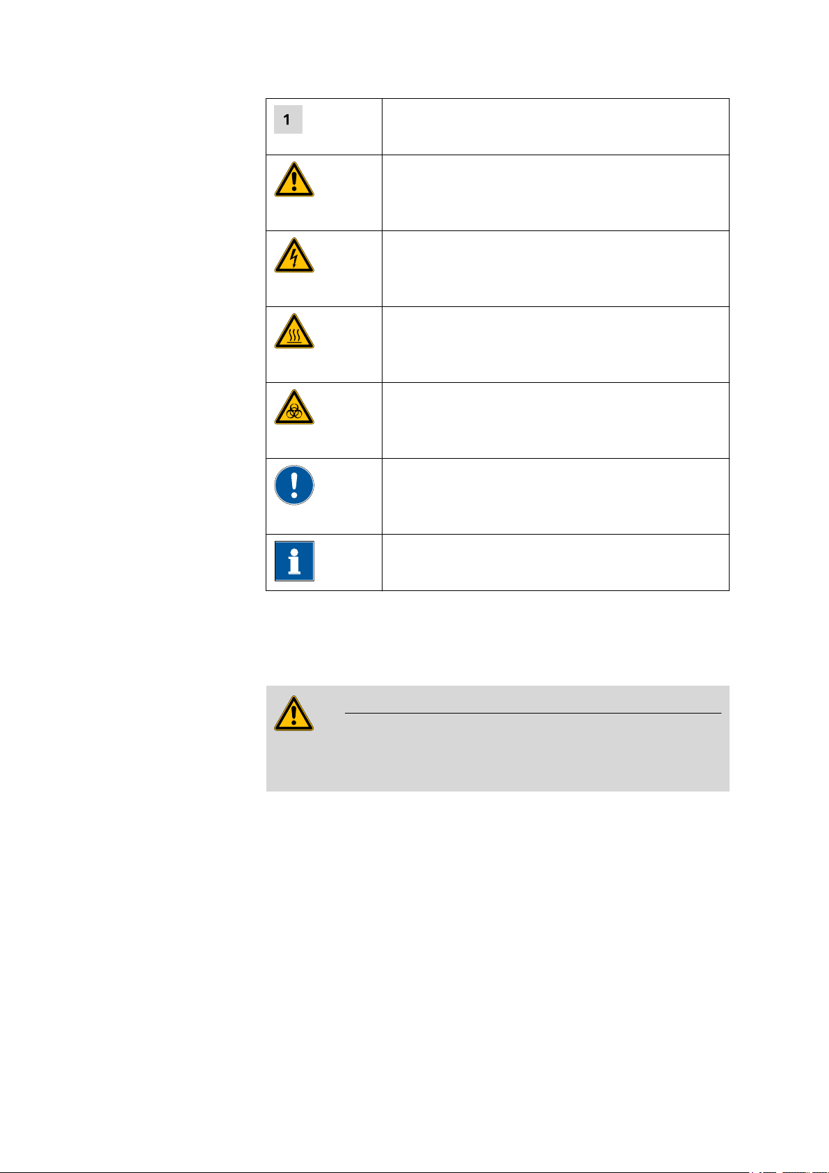
1.2.1 Symbols and conventions
The following symbols and styles are used in this documentation:
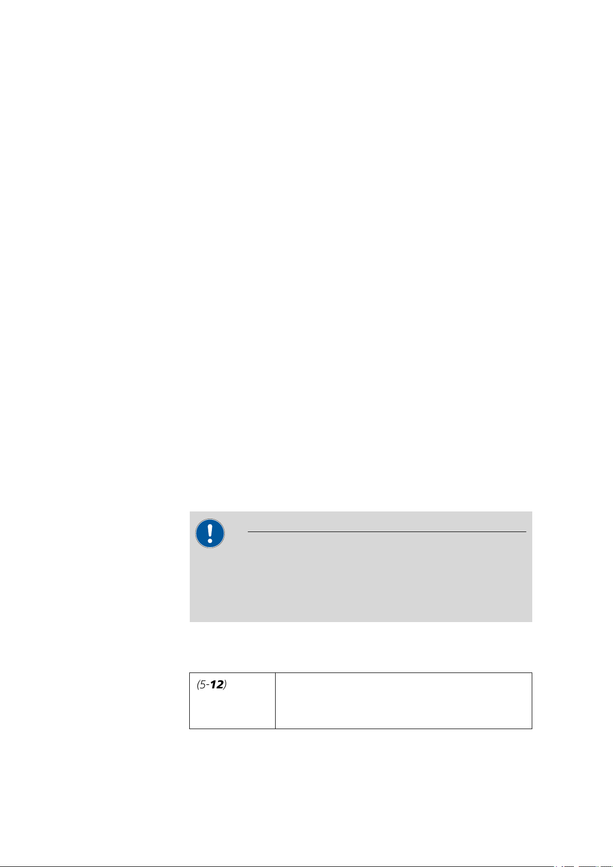
Cross-reference to figure legend
■■■■■■■■
2
The first number refers to the figure number, the
second to the instrument part in the figure.
889 IC Sample Center
Page 11
■■■■■■■■■■■■■■■■■■■■■■
1 Introduction
Instruction step
Carry out these steps in the sequence shown.
Warning
This symbol draws attention to a possible life hazard
or risk of injury.
Warning
This symbol draws attention to a possible hazard due
to electrical current.
Warning
This symbol draws attention to a possible hazard due
to heat or hot instrument parts.
Warning
This symbol draws attention to a possible biological
hazard.
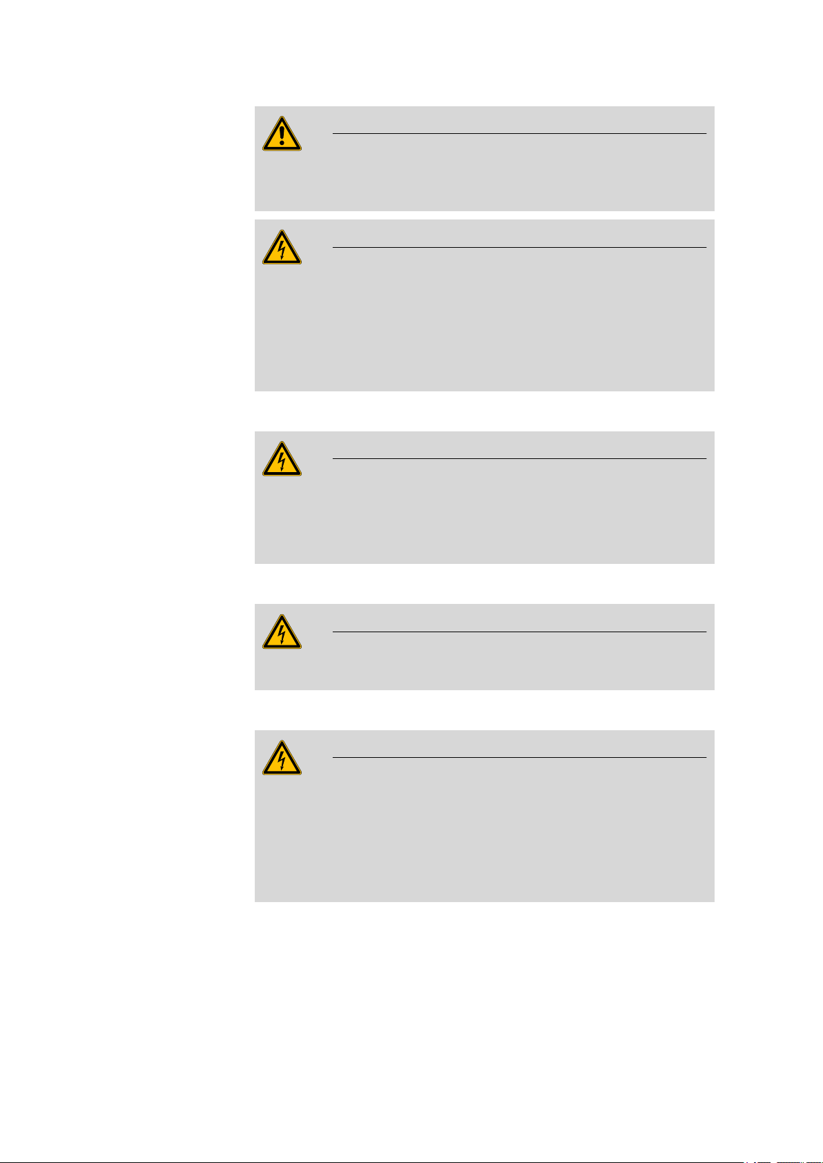
1.3 Safety instructions
1.3.1 General notes on safety
Warning
This instrument may only be operated in accordance with the specifications in this documentation.
This instrument has left the factory in a flawless state in terms of technical
safety. To maintain this state and ensure non-hazardous operation of the
instrument, the following instructions must be observed carefully.
Caution
This symbol draws attention to a possible damage of
instruments or instrument parts.
Note
This symbol marks additional information and tips.
1.3.2 Electrical safety
The electrical safety when working with the instrument is ensured as part
of the international standard IEC 61010.
889 IC Sample Center
■■■■■■■■
3
Page 12
1.3 Safety instructions
■■■■■■■■■■■■■■■■■■■■■■
Warning
Only personnel qualified by Metrohm are authorized to carry out service
work on electronic components.
Warning
Never open the housing of the instrument. The instrument could be
damaged by this. There is also a risk of serious injury if live components
are touched.
There are no parts inside the housing which can be serviced or replaced
by the user.
Mains voltage
Warning
An incorrect mains voltage can damage the instrument.
Only operate this instrument with a mains voltage specified for it (see
rear panel of the instrument).
Mains cable
Warning
Replace or repair defective or frayed insulation of the mains cable.
Protection against electrostatic charges
Warning
Electronic components are sensitive to electrostatic charges and can be
destroyed by discharges.
Always pull the mains cable out of the mains connection socket before
connecting or disconnecting electrical appliances on the rear panel of
the instrument.
■■■■■■■■
4
889 IC Sample Center
Page 13
■■■■■■■■■■■■■■■■■■■■■■
Fuses
Warning
Replaced burned fuses only with new fuses of the same size and the
same type, as specified next to the fuse holder or in the accessories list
in this manual.
1.3.3 Tubing and capillary connections
Caution
Leaks in tubing and capillary connections are a safety risk. Tighten all
connections well by hand. Avoid applying excessive force to tubing
connections. Damaged tubing ends lead to leakage. Appropriate tools
can be used to loosen connections.
Check the connections regularly for leakage. If the instrument is used
mainly in unattended operation, then weekly inspections are mandatory.
1 Introduction
1.3.4 Personnel safety
Wear protective goggles and working clothes suitable for laboratory
work while operating the 889 IC Sample Center. It is also advisable to
wear gloves when caustic liquids are used or in situations where glass
vessels could break.
Personnel are not permitted to reach into the working area of the
instrument while operations are running!
A considerable risk of injury exists for the user.
Warning
Warning
889 IC Sample Center
■■■■■■■■
5
Page 14
1.3 Safety instructions
Warning
In the event of a possible jamming of a drive, the mains plug must be
pulled out of the socket immediately. Do not attempt to free jammed
sample vessels or other parts while the instrument is switched on.
Blockages can only be cleared when the instrument is in a voltage-free
status; this action generally involves a considerable risk of injury.
1.3.5 Flammable solvents and chemicals
Warning
All relevant safety measures are to be observed when working with
flammable solvents and chemicals.
■ Set up the instrument in a well-ventilated location.
■ Keep all sources of flame far from the workplace.
■ Clean up spilled liquids and solids immediately.
■ Follow the safety instructions of the chemical manufacturer.
■ Dispose of solvents and chemicals according to good professional
practice.
■■■■■■■■■■■■■■■■■■■■■■
1.3.6 Recycling and disposal
This product is covered by European Directive 2002/96/EC, WEEE – Waste
from Electrical and Electronic Equipment.
The correct disposal of your old equipment will help to prevent negative
effects on the environment and public health.
More details about the disposal of your old equipment can be obtained
from your local authorities, from waste disposal companies or from your
local dealer.
■■■■■■■■
6
889 IC Sample Center
Page 15
■■■■■■■■■■■■■■■■■■■■■■
1
2
3
4
2 Overview of the instrument
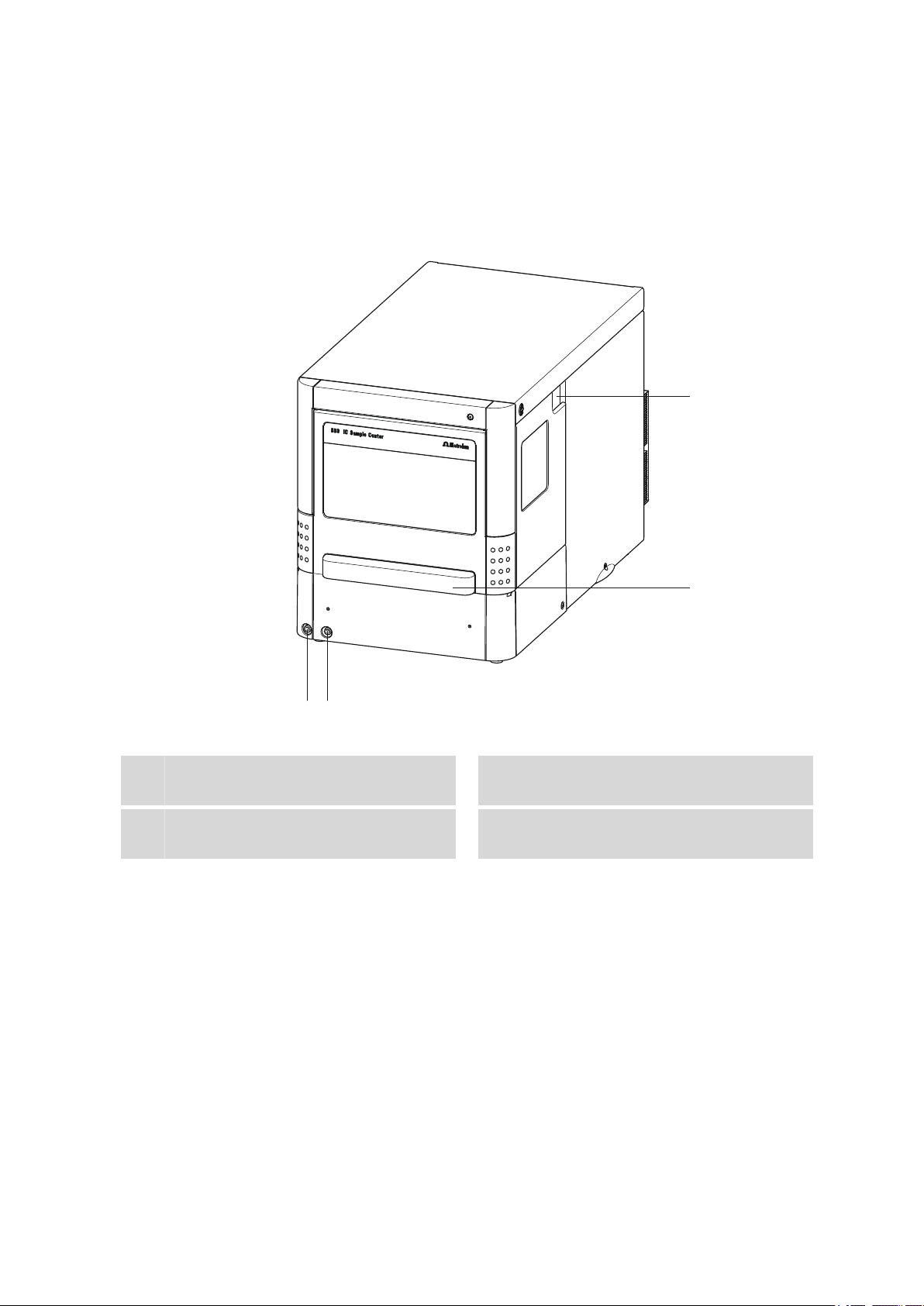
2.1 Front and rear
2 Overview of the instrument
Tubing guide
1
For capillaries and tubings.
Connector for the outlet tubing
3
889 IC Sample Center
Figure 1 889 IC Sample Center - front
Door to the sample chamber
2
With handle.
Connector for the condensation and
4
leakage tubing
■■■■■■■■
7
Page 16
2.2 Opening the device
1
2
3
4
5
■■■■■■■■■■■■■■■■■■■■■■
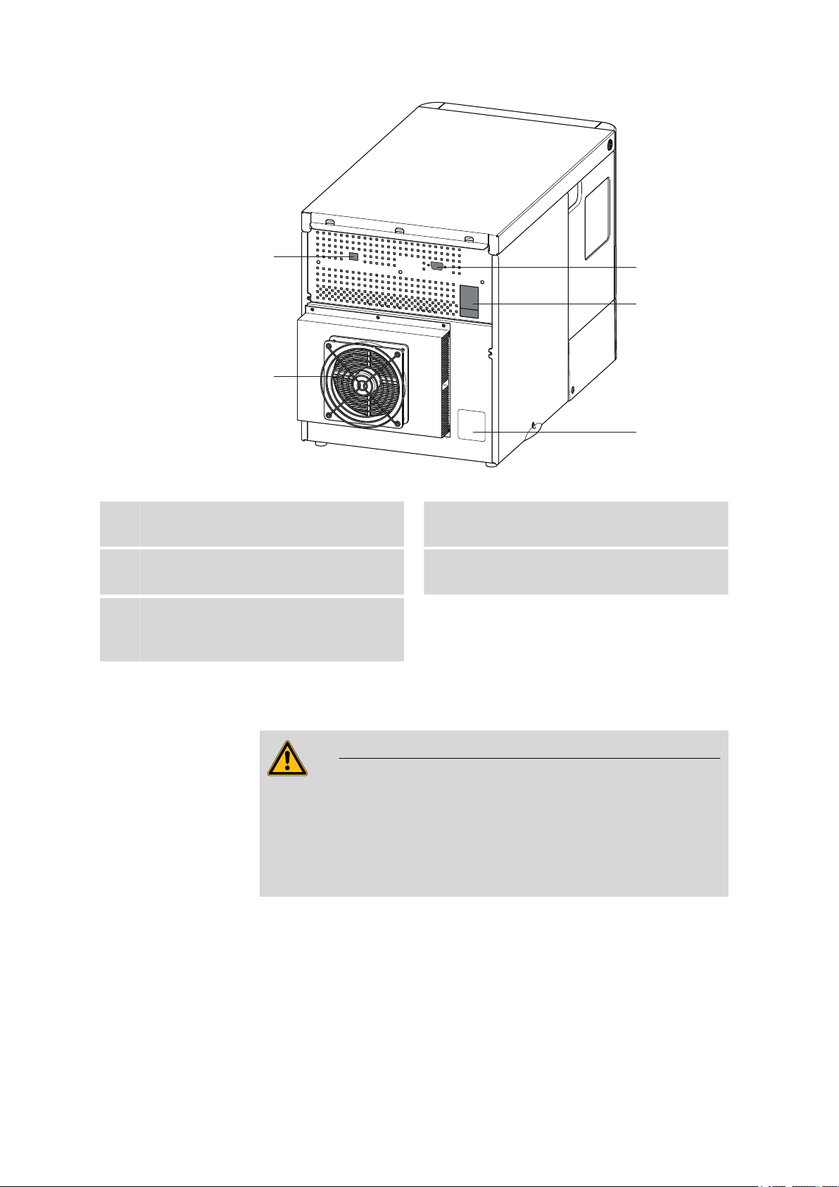
Figure 2 889 IC Sample Center - rear
USB connector
1
For the connection to a PC.
I/O connector
3
For output of an inject marker signal.
Type plate
5
Contains specifications concerning mains
voltage and serial number.
2.2 Opening the device
Warning
Mobile parts are to be found in the interior of the 889 IC Sample Center. Reaching into the interior during operation puts personnel at a serious risk of injury. Open the door only if the device is in idle mode. Due
to safety considerations, no needle movements are carried out by the
device when the door is open.
Fan
2
For the cooling unit. Do not cover!
Mains connection socket
4
With mains switch and fuse holder.
■■■■■■■■
8
889 IC Sample Center
Page 17
■■■■■■■■■■■■■■■■■■■■■■
2 Overview of the instrument
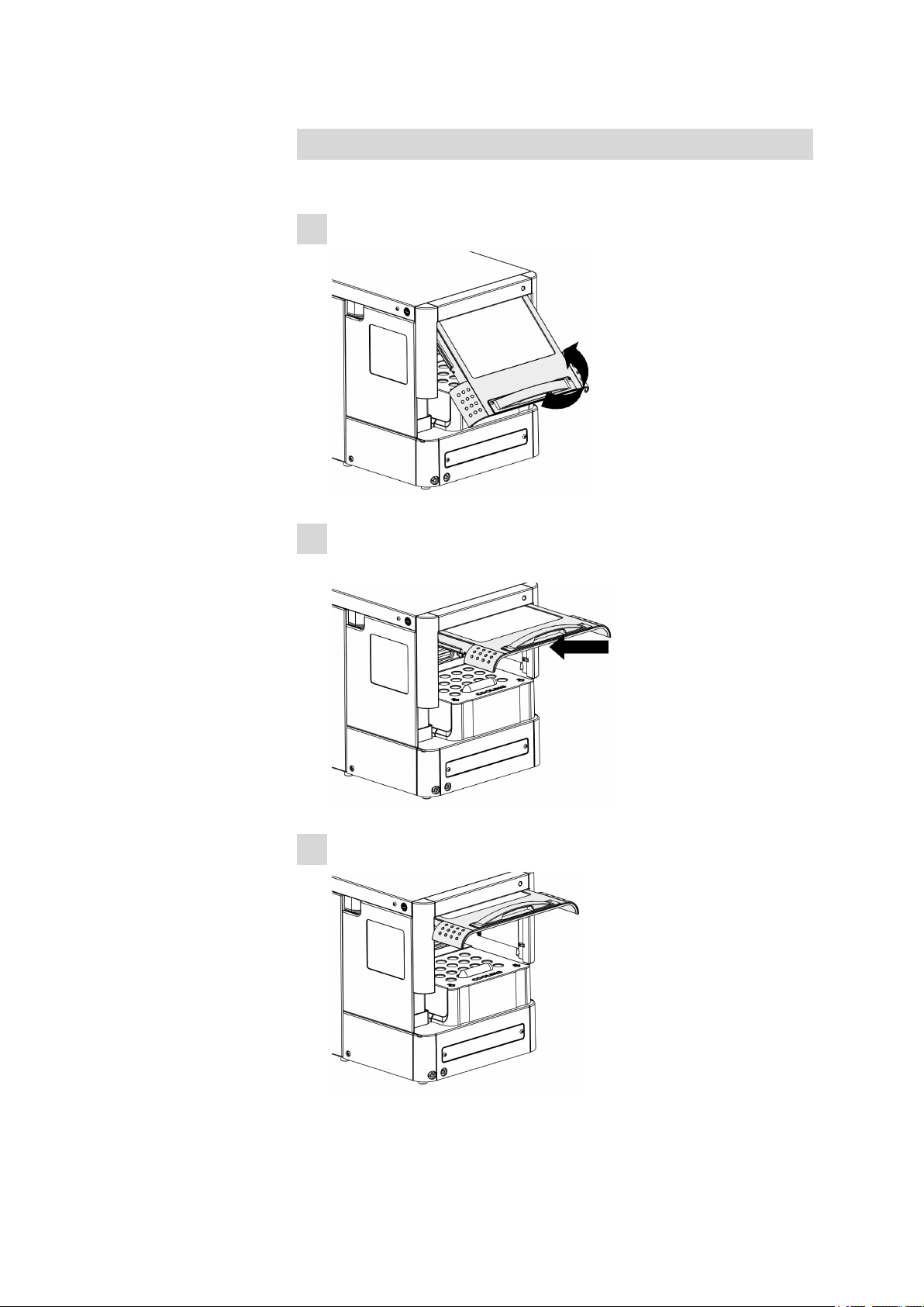
Opening the door
Proceed as follows:
Grip the door handle:
1
Carefully pull out the door and press it upwards until it is in a hori-
2
zontal position.
889 IC Sample Center
Slide the door into the housing.
3
■■■■■■■■
9
Page 18
2.3 Interior view
■■■■■■■■■■■■■■■■■■■■■■
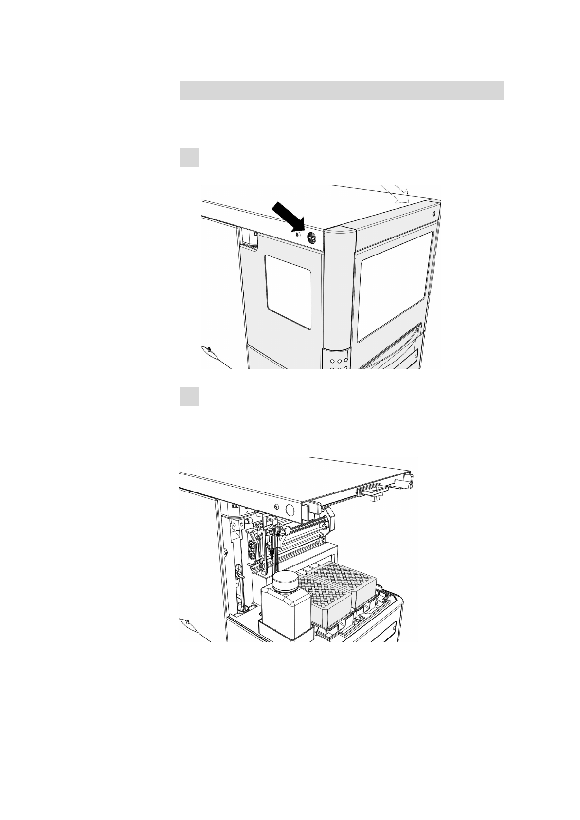
Removing the covering
You can remove the covering on the housing in order to make the interior
more readily accessible:
Press the two black buttons on the sides of the housing (above)
1
simultaneously.
Carefully pull out the covering towards the front.
2
2.3 Interior view
Figure 3
Interior view without covering
■■■■■■■■
10
889 IC Sample Center
Page 19
■■■■■■■■■■■■■■■■■■■■■■
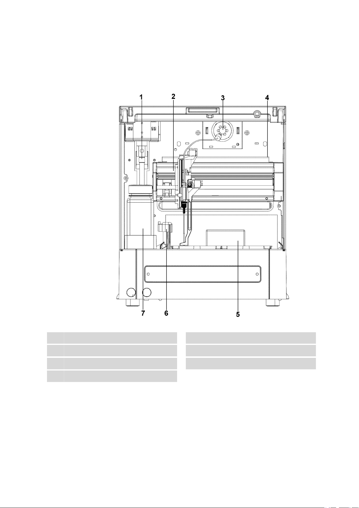
2.4 Interior
2 Overview of the instrument
The following parts are to be found in the interior of the 889 IC Sample
Center:
Syringe
1
Injection valve
3
Sample chamber
5
Washing bottle
7
889 IC Sample Center
Figure 4 Interior with sampling device
Needle arm
2
Sample drip pan
4
Needle washing position
6
■■■■■■■■
11
Page 20
2.5 Cooling option
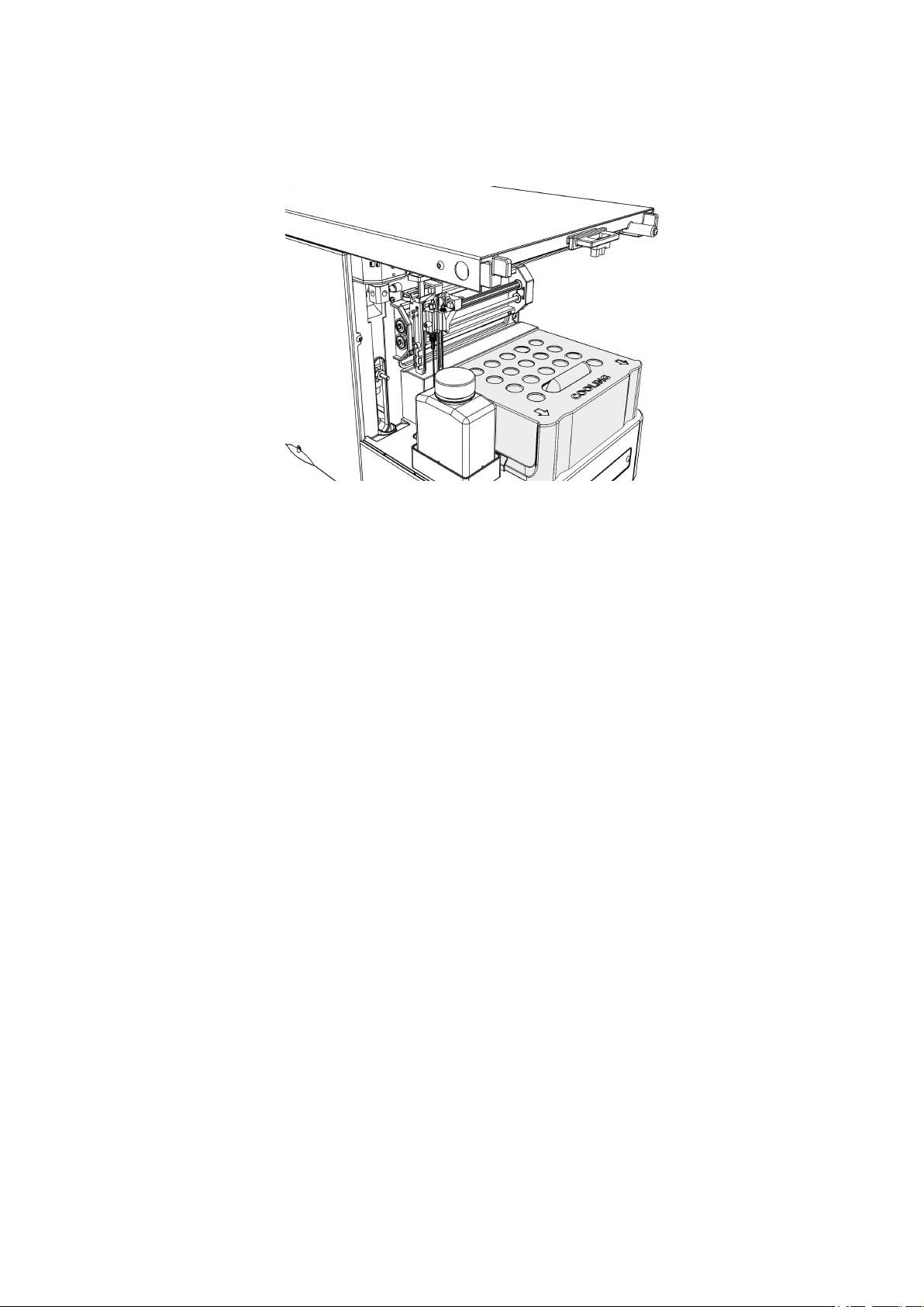
2.5 Cooling option
Figure 5 Interior with installed cooling option.
■■■■■■■■■■■■■■■■■■■■■■
If the cooling option is installed, pull the covering of the cooling option off
towards the front. Now you can place the sample racks or micro titer
plates.
■■■■■■■■
12
889 IC Sample Center
Page 21
■■■■■■■■■■■■■■■■■■■■■■
3 Installation
3.1 Setting up the instrument
3.1.1 Packaging
The instrument is supplied in highly protective special packaging together
with the separately packed accessories. Keep this packaging, as only this
ensures safe transportation of the instrument.
3.1.2 Checks
Immediately after receipt, check whether the shipment has arrived complete and without damage by comparing it with the delivery note.
3.1.3 Location
The instrument has been developed for operation indoors and may not be
used in explosive environments.
3 Installation
Place the instrument in a location of the laboratory suitable for operation
and free of vibrations, if possible protected from corrosive atmospheres
and contamination by chemicals.
The instrument should be protected against excessive temperature fluctuations and direct sunlight.
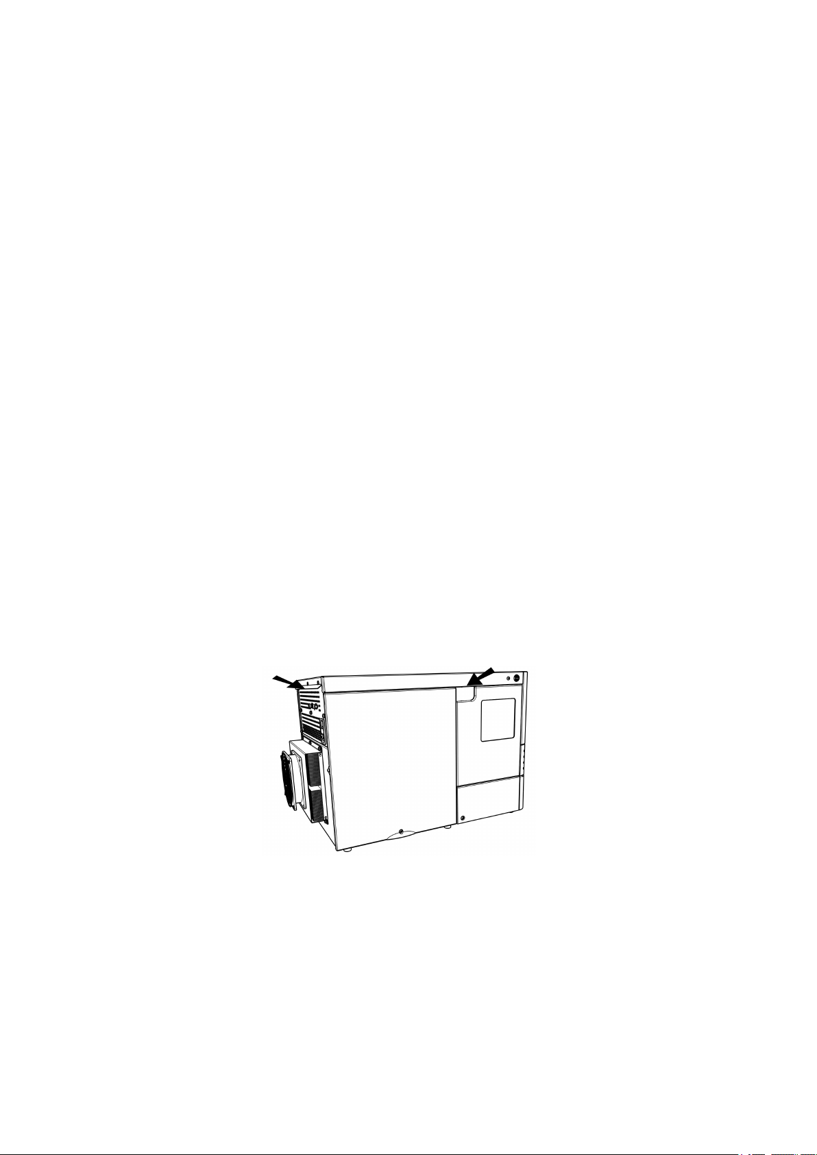
3.1.4 Removing the device from the packaging
Grip the device at the positions marked with arrows and lift it out of the
packaging.
Figure 6
Unpacking the 889 IC Sample Center
889 IC Sample Center
Grip the device underneath with both hands when you are transporting it.
Always hold the device in an upright position.
Before you switch on the 889 IC Sample Center, allow the device to stand
for at least one hour in order to adapt to the room temperature.
■■■■■■■■
13
Page 22

3.2 Connecting a computer
Warning
Take care to ensure that the ventilation openings on the rear side of the
device are not covered. Note that blocked ventilation openings could
have an influence on the performance of the device, in particular on its
cooling output.
Objects placed on the device could also impair the cooling output.
Objects can be placed at the sides of the 889 IC Sample Center. If an
object is placed on only one side, then a minimum clearance of 5 cm must
be maintained. In the case of more than one sides, a minimum clearance
of 10 cm applies.
3.2 Connecting a computer
The 889 IC Sample Center requires a USB connection to a computer in
order to be able to be controlled by a PC software. When a 6.2151.020
cable USB A - USB B is used, the instrument can be connected directly,
either to a USB socket on a computer, to a connected USB hub or to a
different Metrohm control instrument.
■■■■■■■■■■■■■■■■■■■■■■
Cable connection and driver installation
A driver installation is required in order to ensure that the 889 IC Sample
Center is recognized by the PC software. To accomplish this, you must
comply with the procedures specified. The following steps are necessary:
1
Installing software
■ Insert the MagIC Net™ PC software installation CD and carry
out the installation program directions.
■ Exit the program if you have started it after the installation.
2
Establishing cable connections
■ Check whether the fuse and the supply voltage which are speci-
fied on the rear side of the device also match the prevailing circumstances.
■ Connect the 889 IC Sample Center to the mains supply.
■ Connect the instrument to a USB connector (Type A) of your com-
puter (see manual of your computer). The 6.2151.020 cable
USB A - USB B is used for this purpose. The USB connector of
the 889 IC Sample Center is located on the rear of the instrument.
■■■■■■■■
14
889 IC Sample Center
Page 23

■■■■■■■■■■■■■■■■■■■■■■
3 Installation
Switch on the instrument using the mains switch on the rear of the
3
instrument.
For Windows 2000: the instrument is recognized and the driver is
installed automatically.
For Windows XP: the instrument is recognized and the installation
assistant for the driver is started automatically. Select the option
"Install software automatically" and click on [Next]. Exit the assistant
with [Finish].
For Windows Vista: the instrument is recognized and the installation assistant for the driver is started automatically. Select the option
"Find and install driver software". Agree to all of the requests that
follow. The installation assistant will be exited automatically.
Registering and configuring the instrument in the PC software
The instrument must be registered in the configuration of MagIC Net™ .
Once that has been done, you can then configure it according to your
requirements. Proceed as follows:
1
Setting up the instrument
■ Start MagIC Net™ .
The instrument is recognized automatically. The configuration dialog for the instrument is displayed.
■ Make configuration settings for the instrument.
More detailed information concerning the configuration of the
instrument can be found in the documentation of MagIC Net™ .
3.3 Connecting pump and column
The 889 IC Sample Center is supplied with the necessary mounted hose
and capillary connections. Connect the high pressure pump and the separation columns to the still unoccupied ports 1 and 6 on the injection valve
with one suitable PEEK capillary each (6.1831.010). Observe the following
illustration.
889 IC Sample Center
■■■■■■■■
15
Page 24

3.4 Tubing
1
2
3
4
5
6
4
2
5
3
1
■■■■■■■■■■■■■■■■■■■■■■
Figure 7 Connecting pump and column
Connection to the syringe module
1
Port 3 of the injection valve.
Connection to the high pressure pump
3
Port 1 of the injection valve.
Sample loop
5
Port 2 and 5 of the injection valve.
3.4 Tubing
The 889 IC Sample Center is equipped with the following standard tubing:
Tubing/Capillary
Standard sample needle and
capillary (15 µL)
Buffer tubing from the high
pressure valve to the syringe
valve (1000 µL)
Connection to the needle
2
Port 4 of the injection valve.
Connection to the separation column
4
Port 6 of the injection valve.
Material/Dimensions
SS (inert-coated): 97 mm x 0.8 mm
OD x 0.25 mm ID
ETFE (Tefzel): 200 mm x 1/16" OD x
0.25 mm ID
ETFE (Tefzel): 1275 mm x 1/16" OD x
1.0 mm ID
Tubing from the syringe valve
to the washing bottle
Tubing from the syringe valve
PTFE: 400 mm x 1/18" OD x 1.6 mm
ID
PTFE: 400 mm x 1/8" OD x 1.6 mm ID
to the outlet tubing
Observe the following when mounting new tubing or capillaries:
■ Do not tighten the connectors excessively. This could block the flow
path.
■ Make sure that you always use tubing volumes which are suitable for
the other components in the flow path.
16
■■■■■■■■
889 IC Sample Center
Page 25

■■■■■■■■■■■■■■■■■■■■■■
3.4.1 Tubing guide
In order to prevent the rinsing tubing from hindering the horizontal movement of the needle unit, use the tubing guide in the collection pan under
the injection valve:
Figure 8 Guiding the rinsing tubing
3 Installation
Figure 9 Tubing guide from above
3.5 Outlet tubings
Set up the following tubing connections for the disposal of waste fluids:
General waste
Connect one outlet tubing (included in the scope of delivery) on the lefthand tubing connector on the front of the 889 IC Sample Center. Guide
the other end into a waste container underneath the 889 IC Sample Center.
Figure 10
All of the liquid which is conveyed to the washing position will be channeled through this outlet. Sample liquid which was not injected will also
be disposed of through this outlet.
Mounting the outlet tubing
889 IC Sample Center
■■■■■■■■
17
Page 26

3.6 Rinsing the syringe
Condensation and leakage outlet
All leakage liquid and condensation water (from the cooling module) will
be channeled through the right-hand tubing connector. If the cooling
option is used, it is advisable to connect this connector with a waste container underneath the 889 IC Sample Center.
Figure 11 Mounting the leakage tubing
3.6 Rinsing the syringe
The syringe must be rinsed bubble-free prior to the start-up of the 889 IC
Sample Center.
Fill the washing bottle with isopropanol.
■■■■■■■■■■■■■■■■■■■■■■
Warning
Do not use any saline or buffer solutions. Crystals could block or damage the entire system.
Proceed as follows:
Immerse the end of the tubing for the washing bottle into the vessel.
1
Open the manual control in MagIC Net™.
2
Select 889 IC Sample Center in the device selection (all devices).
3
On the tab General, carry out the function Washing.
4
The syringe, the needle and the tubing are rinsed thoroughly.
If needed, carry out the function a second time until the syringe no
5
longer contains any bubbles and the tubing is filled.
Repeat the washing procedure with ultra pure water or possibly with
6
eluent.
■■■■■■■■
18
889 IC Sample Center
Page 27

■■■■■■■■■■■■■■■■■■■■■■
1
2
3
4
5
4 Functioning
4.1 Injection modes
Three different injection modes can be utilized:
■ Full loop injection: for full precision
■ Partial loopfill injection: for full flexibility
■ Pickup injection: for smallest loss of sample
The sample loop injection with pressure-assisted sample aspiration =
PASA™ can be used with all three injection modes. This is a tried and tested concept which combines high accuracy with simplicity and reliability.
■ No movement of the sample needle
■ Reduced risk of bubbles in the sample intake
■ No wearing or contamination of the injection port
4 Functioning
Buffer loop
1
Separation column
3
Compressed air
5
889 IC Sample Center
Figure 12
PASA™ injection concept
High pressure pump
2
Sample loop
4
The syringe aspirates the sample out of the sample vessel and into the
sample loop. The buffer loop between the syringe and the injection valve
■■■■■■■■
19
Page 28

4.2 Syringe and buffer loop
prevents the contamination of the syringe. Washing solution is required in
order to:
■ remove the sample from the buffer loop and the sample needle.
■ rinse the buffer loop and the sample needle.
4.2 Syringe and buffer loop
The following range of sample volumes can be covered with the various
injection modes using the 500 µL syringe, in combination with the standard buffer loop (1000 µL) and the standard sample loop (100 µL):
■ Full loop: 100 µL
■ Partial loopfill: 1…50 µL
■ Pickup: 1…27 µL
The maximum injection volume is calculated in accordance with the following formulas:
■ Full loop: injection volume = sample loop volume
■ Partial loopfill: max. injection volume = 0.5 × sample loop volume
■ Pickup: max. injection volume = (sample loop volume – 3 × needle vol-
ume) / 2
■■■■■■■■■■■■■■■■■■■■■■
The full loop injection yields the maximum possible reproducibility < 0.3%,
but not the maximum accuracy, because the loop volume is specified as
being with an accuracy of ±10%. The minimum sample loss is 230 µL (2 ×
(sample loop overfilling + rinsing volume) for one 15 µL needle).
The partial loopfill injection yields a maximum accuracy and reproducibility
better than 0.5% relative standard deviation (RSD) for injection volumes
> 10 µL. The minimum sample loss (rinsing volume is equal to 30 µL.
30 µL is the recommended minimum rinsing volume. Smaller rinsing volumes can be programmed, but reproducibility will be reduced as a result.
The pickup injection offers maximum accuracy (the same as with partial
loopfill) and no loss of sample, but somewhat lower reproducibility,
namely a relative standard deviation (RSD) better than 1% for injection
volumes > 10 µL.
■■■■■■■■
20
889 IC Sample Center
Page 29

■■■■■■■■■■■■■■■■■■■■■■
4.3 Full loop injection
The sample loop is filled completely (quantitatively) with sample. This type
of injection results in excellent reproducibility.
1
Initial situation
4 Functioning
Figure 13 Full loop injection
The injection valve is in INJECT position. The sample needle penetrates the vial with the air needle. An overpressure channeled in
through the air needle ensures that no air or steam bubbles form
during the aspiration of the sample.
2
Rinsing the aspirating line
889 IC Sample Center
■■■■■■■■
21
Page 30

4.3 Full loop injection
■■■■■■■■■■■■■■■■■■■■■■
The syringe aspirates a rinsing volume of sample solution out of the
sample vial and fills the sample line with sample. The rinsing liquid is
expelled.
3
Switching the injection valve to LOAD
The injection valve is switched over to the LOAD position. This causes an homogenous sample plug to be present at the inlet to the
sample loop.
4
Filling the sample loop
■■■■■■■■
22
The sample loop is quantitatively filled by a multiple of the loop volume being pumped through the loop.
■ 3 × loop volume with sample loops ≤ 100 µL
889 IC Sample Center
Page 31

■■■■■■■■■■■■■■■■■■■■■■
■ 2 × loop volume with sample loops 100...500 µL
■ 1.5 × loop volume with sample loops ≥ 500 µL
5
Switching the injection valve to INJECT
4 Functioning
The injection valve switches to the INJECT position. The sample loop
is now part of the flow path of the eluent; the sample is transported
to the separation column. The determination is started.
A washing cycle is performed after each injection.
Air segment with the full loop injection
A 5 µL air segment can be used in order to reduce the necessary volume
of sample solution. The air segment must be located at the head of the
rinsing volume and will not be injected.
In the case of a standard needle, the rinsing volume with air segment
must be at least 30 µL for one injection, and at least 35 µL for injections
without air segments. In the case of high-viscosity samples, larger rinsing
volumes must be programmed and the speed of the syringe stroke must
be reduced in order to improve reproducibility.
889 IC Sample Center
■■■■■■■■
23
Page 32

4.4 Partial loopfill injection
4.4 Partial loopfill injection
The switchover sequence for the partial loopfill injection is as follows:
1
Initial situation
■■■■■■■■■■■■■■■■■■■■■■
The injection valve is in INJECT position. The sample needle penetrates the vial with the air needle. An overpressure channeled in
through the air needle ensures that no air or steam bubbles form
during the aspiration of the sample.
2
Rinsing the aspirating line
■■■■■■■■
24
889 IC Sample Center
Page 33

■■■■■■■■■■■■■■■■■■■■■■
4 Functioning
The syringe aspirates a rinsing volume of sample solution out of the
sample vial and fills the sample line with sample. The rinsing liquid is
expelled.
3
Switching the injection valve to LOAD
The injection valve is switched over to the LOAD position. This causes an homogenous sample plug to be present at the inlet to the
sample loop.
4
Filling the sample loop partially
889 IC Sample Center
The programmed injection volume is now aspirated into the sample
loop.
■■■■■■■■
25
Page 34

4.4 Partial loopfill injection
■■■■■■■■■■■■■■■■■■■■■■
5
Switching the injection valve to INJECT
The injection valve switches to the INJECT position. The sample loop
is now part of the flow path of the eluent; the sample is transported
to the separation column. The determination is started.
Air segment with the partial loopfill injection
An air segment can be used in order to reduce the necessary volume of
sample solution. The air segment must be located at the head of the rinsing volume and will not be injected.
In the case of a standard needle, the rinsing volume with air segment
must be at least 30 µL for one injection, and at least 35 µL for injections
without air segments. In the case of high-viscosity samples, larger rinsing
volumes must be programmed and the rate of the syringe stroke must be
reduced in order to improve reproducibility.
■■■■■■■■
26
889 IC Sample Center
Page 35

■■■■■■■■■■■■■■■■■■■■■■
4.5 Pickup injection
The switchover sequence for the pickup injection is as follows:
Initial situation
1
4 Functioning
The injection valve is in INJECT position. The sample needle is in
washing position.
2
Rinsing the washing reservoir
The washing reservoir is filled several times (the number of times can
be programmed) with the syringe volume. This takes place after a
washing sequence or after the buffer tubing has been emptied. The
injection valve remains in INJECT position. Note that the transport
solution must be compatible with the eluent.
3
Filling the aspirating line with transport solution
For the first injection, the syringe aspirates a segment of transport
solution in order to fill the sample line with transport solution.
889 IC Sample Center
■■■■■■■■
27
Page 36

4.5 Pickup injection
■■■■■■■■■■■■■■■■■■■■■■
4
Switching the injection valve to LOAD
The needles switches from the washing position to the sample vial.
The injection valve switches to the LOAD position.
5
Aspirating sample
■■■■■■■■
28
The programmed injection volume is aspirated from the sample vial.
889 IC Sample Center
Page 37

■■■■■■■■■■■■■■■■■■■■■■
4 Functioning
6
Transporting sample into the sample loop
The sample needle moves back to the washing position. A second
segment of transport solution is aspirated. The sample is transported
quantitatively into the sample loop.
7
Switching the injection valve to INJECT
889 IC Sample Center
The injection valve switches to the INJECT position. The sample loop
is now part of the flow path of the eluent; the sample is transported
to the separation column. The determination is started.
This sequence is repeated for each injection.
■■■■■■■■
29
Page 38

4.5 Pickup injection
■■■■■■■■■■■■■■■■■■■■■■
Air segment in the pickup injection
If an air segment was programmed, this will appear at the beginning of
the first segment of the transport solution and at the beginning of each
sample segment.
The following is to be observed for this injection technique:
Note
The air segment at the beginning of the sample segment is injected
onto the separation column.
Note
No overpressure is permitted to be applied in the sample vessel,
because the air segment would expand during the change from sample
position to transport position. This could lead to a considerable error
with respect to the injection volume of the sample.
■■■■■■■■
30
889 IC Sample Center
Page 39

■■■■■■■■■■■■■■■■■■■■■■
5 Handling and maintenance
5.1 General
The 889 IC Sample Center requires appropriate care. Excess contamination
of the instrument may result in functional disruptions and a reduction in
the service life of the sturdy mechanics and electronics of the instrument.
Severe contamination can also have an influence on the measured results.
Regular cleaning of exposed parts can prevent this to a large extent.
Spilled chemicals and solvents must be removed immediately. In particular,
the mains plug should be protected from contamination.
Note
It is not necessary to disconnect the device from the electricity source
for care and maintenance work. This means that it is possible to continue to operate the device with the control software. Use Manual
operation in MagIC Net™ to check the functioning of the individual
device components.
5 Handling and maintenance
5.2 Care
The following applies for all care and maintenance work:
Open the door of the 889 IC Sample Center.
1
If the cooling option is installed, remove the covering of the cooling
2
option by pulling it towards the front.
Press the two buttons on the sides of the device simultaneously.
3
Remove the covering by pulling towards the front.
4
5.2.1 Cleaning in general
Generally speaking, the 889 IC Sample Center requires little upkeep. Clean
the outside of the housing with a soft cloth and a mild cleaning fluid.
Other parts which require regular care include:
■ Valve drip pan. A special drip pan is fitted underneath the injection
valve. Clean this with a soft cloth and a mild cleaning fluid.
889 IC Sample Center
■■■■■■■■
31
Page 40

5.3 Maintenance and service
■ Sample rack. If sample has been spilled on the sample rack, clean this
with a soft cloth and a mild cleaning fluid.
■ Drainage lines. Rinse the drainage tubing regularly in order to pre-
vent blockage and to ensure the drainage of liquids and condensation
water.
5.3 Maintenance and service
5.3.1 Sample loop
The 889 IC Sample Center is equipped as standard with a 100 µL sample
loop. Other sample loops can be mounted. Please note however that the
correct combination of syringe and buffer loop is required in order to achieve good results.
Observe the following when mounting a sample loop:
■ Mount the sample loop at Port 2 and Port 5 of the injection valve.
■ Adjust the configuration settings in the control software for the
changed sample loop volume.
■■■■■■■■■■■■■■■■■■■■■■
Note
The maximum injection volume is calculated in accordance with the following formulas:
Full loop: Injection volume = Loop volume
Partial loopfill: max. injection volume = 0.5 × loop volume
µL Pickup: max. injection volume = (loop volume – 3 × needle volume)
/ 2
■■■■■■■■
32
889 IC Sample Center
Page 41

■■■■■■■■■■■■■■■■■■■■■■
5.3.2 Replacing the sample needle
5 Handling and maintenance
889 IC Sample Center
Figure 14 Replacing the sample needle
Replace the sample needle as follows:
Open the Manual control in MagIC Net™ .
1
Under device selection, 889 IC Sample Center, select the tab Nee-
2
dle. Under Position/Input, select Exchange position and click on
[Start].
Now a message window is displayed.
Remove the sample rack and click on [OK].
3
■■■■■■■■
33
Page 42

5.3 Maintenance and service
■■■■■■■■■■■■■■■■■■■■■■
The needle moves into the exchange position.
Open the door of the 889 IC Sample Center.
4
If working with the cooling option, remove the covering of the cool-
5
ing option by pulling it towards the front.
Press the two buttons on the sides of the device simultaneously.
6
Remove the covering by pulling towards the front.
7
Loosen the nut 3 of the capillary connection.
8
Undo the tubing connection at Port 4 on the injection valve.
9
Remove the sample needle by pulling it upward and out of its seat.
10
Load a new sample needle. Ensure while doing so that the seal sur-
11
rounds the needle.
Tighten the sample needle with the connection nut.
12
Mount the other end of the capillary connection to port 4 of the
13
injection valve. Do not screw too tightly. This may block the tubing
connection.
Put the device covering back into position.
14
If working with the cooling option, replace the covering of the cool-
15
ing option.
Close the door of the 889 IC Sample Center.
16
Select the General tab in the manual control and start the Reset
17
device function.
■■■■■■■■
34
The sample needle moves back to the starting position.
889 IC Sample Center
Page 43

■■■■■■■■■■■■■■■■■■■■■■
5 Handling and maintenance
Note
If you are using the sample racks with 12 or 48 vials, then you
must adjust the setting of the needle height to > 2 mm. This will
prevent the needle from touching the bottom of the vial.
Perform a rinsing procedure in order to clean the new needle. Start
18
the Wash function. To interrupt the rinsing procedure, click on
Stop.
19
Note
The needle settings may need to be adjusted.
In MagIC Net™, open the configuration settings of the 889 IC Sam-
ple Center and select the Needle tab.
Perform the necessary setting.
5.3.3 Replacing the air needle
Replace the air needle as follows:
Replace the sample needle, (see Chapter 5.3.2, page 33).
1
Undo the fastening nut (made of chrome) for the air needle.
2
Undo the fastening nut (made of chrome) for the adjusting screw.
3
Remove the air needle.
4
Tighten the height adjustment nut on the fixing nut (made of
5
chrome). The thread of the height adjustment nut must match the
lower part of the fixing nut. The O-ring must be properly seated in
the fixing nut.
Insert the air needle.
6
Mount the sample needle.
7
Select the correct needle height for the new needle in the manual
8
operation feature of MagIC Net™ on the Needle tab.
889 IC Sample Center
■■■■■■■■
35
Page 44
5.3 Maintenance and service
If you are using the sample racks with 12 or 48 vials, then you
must adjust the setting of the needle height to > 2 mm. This will
prevent the needle from touching the bottom of the vial.
Perform a rinsing procedure in order to clean the new needle. On the
9
General tab, under Wash, click on Start. To interrupt the rinsing
procedure, click on Stop.
5.3.4 Replacing the fuses
The fuses installed in the 889 IC Sample Center are of the type
2 × 2.5 A
■■■■■■■■■■■■■■■■■■■■■■
Note
Warning
The device must be disconnected from the electricity source before the
fuses are replaced.
Make sure that the fuses to be installed correspond to the correct type
and the correct power load.
The fuses are located in the fuse holder at the rear of the device.
Note
Contact a service technician in the event of repeated problems with the
fuses.
■■■■■■■■
36
889 IC Sample Center
Page 45

■■■■■■■■■■■■■■■■■■■■■■
5 Handling and maintenance
5.4 Quality Management and validation with Metrohm
Quality Management
Metrohm offers you comprehensive support in implementing quality management measures for instruments and software. Further information on
this can be found in the brochure «Quality Management with
Metrohm» available from your local Metrohm agent.
Validation
Please contact your local Metrohm agent for support in validating instruments and software. Here you can also obtain validation documentation
to provide help for carrying out the Installation Qualification (IQ) and
the Operational Qualification (OQ). IQ and OQ are also offered as a
service by the Metrohm agents. In addition, various application bulletins
are also available on the subject, which also contain Standard Operat-
ing Procedures (SOP) for testing analytical measuring instruments for
reproducibility and correctness.
Maintenance
Electronic and mechanical functional groups in Metrohm instruments can
and should be checked as part of regular maintenance by specialist personnel from Metrohm. Please ask your local Metrohm agent regarding the
precise terms and conditions involved in concluding a corresponding
maintenance agreement.
Note
You can find information on the subjects of quality management, validation and maintenance as well as an overview of the documents currently available at www.metrohm.com/com/ under Support.
889 IC Sample Center
■■■■■■■■
37
Page 46

6.1 Error list
6 Troubleshooting
The 889 IC Sample Center is controlled by the MagIC Net™ PC software.
If a problem occurs which is directly related to the 889 IC Sample Center,
then an error number will be identified in a message window. The significance of the error numbers is listed in the following chapter.
6.1 Error list
6.1.1 Rack unit
Problem
Cause Remedy
■■■■■■■■■■■■■■■■■■■■■■
Error 294 The Home sensor of the
rack holder has not been
activated.
Error 295 The current position of the
rack holder deviates more
than 2 mm from the Home
position.
Error 296 The Home sensor has not
been deactivated.
1. Switch off sample changer.
2. Slide the rack holder carefully back and
forth and remove possible obstacles.
3. If possible, slide the rack holder backwards
right to the stop.
4. Switch on sample changer.
If the error occurs again, please call the
Metrohm Service.
1. Switch off sample changer.
2. Slide the rack holder carefully back and
forth and remove possible obstacles.
3. If possible, slide the rack holder backwards
right to the stop.
4. Switch on sample changer.
If the error occurs again, please call the
Metrohm Service.
■ If in one of the following steps the rack
holder has to be moved: first switch off the
sample changer.
■ Ensure that the transport safeguard (foam
material) has been removed from the sample chamber.
■ Remove other possible obstacles in the
area of the rack holder.
■■■■■■■■
38
If the error occurs again, please call the
Metrohm Service.
889 IC Sample Center
Page 47

■■■■■■■■■■■■■■■■■■■■■■
Problem Cause Remedy
6 Troubleshooting
Error 297 The Home sensor of the
rack holder has unexpectedly been activated.
Error 298 The rack is located in an
undefined position.
6.1.2 Needle unit
Problem
Error 303 The needle is located in an
Error 304 The Home sensor for the
Cause Remedy
undefined horizontal position.
horizontal movement of
the needle has not been
activated.
Call the Metrohm Service.
Carry out the function [Reset device] in the
Manual Control of the sample changer.
If the error occurs again, please call the
Metrohm Service.
Carry out the function [Reset device] in the
Manual Control of the sample changer.
If the error occurs again, please call the
Metrohm Service.
1. Check whether the horizontal movement
of the needle is obstructed.
2. If possible, remove possible obstacles.
If the error occurs again, please call the
Metrohm Service.
Error 306 The Home sensor for the
horizontal movement of
the needle has not been
deactivated.
Error 307 The Home sensor for the
horizontal movement of
the needle has unexpectedly been activated.
Error 308 In order to reach the hori-
zontal Home position of
the needle, the expected
number of steps has not
been carried out.
Error 312 The needle is located in an
undefined vertical position.
1. Check whether the horizontal movement
of the needle is obstructed.
2. If possible, remove possible obstacles.
If the error occurs again, please call the
Metrohm Service.
Call the Metrohm Service.
1. Check whether the horizontal movement
of the needle is obstructed.
2. If possible, remove possible obstacles.
If the error occurs again, please call the
Metrohm Service.
Carry out the function [Reset device] in the
Manual Control of the sample changer.
889 IC Sample Center
■■■■■■■■
39
Page 48

6.1 Error list
Problem Cause Remedy
If the error occurs again, please call the
Metrohm Service.
■■■■■■■■■■■■■■■■■■■■■■
Error 313 The Home sensor for the
vertical movement of the
needle has not been activated.
Error 315 The Home sensor for the
vertical movement of the
needle has not been deactivated.
Error 316 The Home sensor for the
vertical movement of the
needle has been unexpectedly activated.
Error 317 When moving the needle
unit vertically the needle
deflector has not recognized a rack, nor a wash or
waste position.
1. Check whether the vertical movement of
the needle unit is obstructed.
2. If possible, remove possible obstacles.
If the error occurs again, please call the
Metrohm Service.
1. Check whether the vertical movement of
the needle unit is obstructed.
2. If possible, remove possible obstacles.
If the error occurs again, please call the
Metrohm Service.
Call the Metrohm Service.
If the error has occurred during moving to a
rack position: ensure that there is a rack with
vials or a micro titer plate on the rack holder.
If the error occurs again, please call the
Metrohm Service.
Error 318 When moving the needle
unit vertically the needle
deflector is blocked.
Error 319 The sample needle arm is
located in an undefined
vertical position.
6.1.3 Syringe unit
Problem
Error 324 The syringe valve has not
Error 330 The Home sensor of the
Cause Remedy
reached the required port.
syringe has not been activated.
1. Check whether the movement of the needle deflector is obstructed.
2. If possible, remove possible obstacles.
If the error occurs again, please call the
Metrohm Service.
Call the Metrohm Service.
Call the Metrohm Service.
1. Check whether the flow path is kinked or
blocked in on one or more places.
2. If possible, free the flow path of blockages.
■■■■■■■■
40
889 IC Sample Center
Page 49

■■■■■■■■■■■■■■■■■■■■■■
Problem Cause Remedy
If the error occurs again, please call the
Metrohm Service.
6 Troubleshooting
Error 331 The Home sensor of the
syringe has unexpectedly
been activated.
Error 332 The required load volume
of the syringe is too high.
Error 333 The required unload vol-
ume of the syringe is too
high.
Call the Metrohm Service.
The permitted load volume is limited by the
maximum syringe volume. The load volume
currently possible depends additionally on the
current position of the syringe plunger.
■ Ensure that the required load volume of
the syringe is lower or the same as the
maximum syringe volume.
■ Check whether the required load volume
can be reached from the current position
of the syringe piston.
■ Before loading the syringe eject enough
volume first or enter a lower load volume.
The permitted unload volume is limited by the
maximum syringe volume. The unload volume
currently possible depends additionally on the
current position of the syringe plunger.
Error 334 The syringe plunger is loca-
ted in an undefined position.
Error 335 The spindle of the syringe
cannot be rotated correctly.
■ Ensure that the required unload volume of
the syringe is lower or the same as the
maximum syringe volume.
■ Check whether the required unload volume
is possible assuming the current position of
the syringe piston.
■ Before unloading the syringe aspirate
enough volume first or enter a lower
unload volume.
Carry out the function [Reset device] in the
Manual Control of the sample changer.
If the error occurs again, please call the
Metrohm Service.
1. Check whether the flow path is kinked or
blocked in on one or more places.
2. If possible, free the flow path of blockages.
If the error occurs again, please call the
Metrohm Service.
889 IC Sample Center
■■■■■■■■
41
Page 50

6.1 Error list
6.1.4 Injection valve unit
Problem Cause Remedy
■■■■■■■■■■■■■■■■■■■■■■
Error 340 The injection valve has not
reached the required port.
Error 341 The consumption warning
limit of the injection valve
has been reached.
Error 342 The sensor of the injection
valve has provided an
unexpected value.
6.1.5 Cooling unit
Problem
Error 347 When switching on the
Cause Remedy
cooling a temperature of
over 48 °C has been measured.
6.1.6 Electronics
Problem
Error 280, 282, 283,
284
Cause Remedy
An electronic error has
occurred in the EEPROM.
Call the Metrohm Service.
Call the Metrohm Service.
Call the Metrohm Service.
Have a look at the technical specifications in
the device manual of the sample changer and
ensure that the range of the operating temperature has not been exceeded.
1. Switch off sample changer.
2. Wait a few seconds.
3. Switch on sample changer.
Error 290 When initializing the sam-
ple changer at least one
critical malfunction has
been found. No injections
can be carried out.
If the error occurs again, please call the
Metrohm Service.
1. Exit MagIC Net.
2. Switch off sample changer.
3. Ensure that the cable between the sample
changer and the PC is connected correctly.
4. Switch on sample changer.
5. Start MagIC Net.
If the error occurs again, please call the
Metrohm Service.
■■■■■■■■
42
889 IC Sample Center
Page 51

■■■■■■■■■■■■■■■■■■■■■■
6.2 Analytical problems
Analytical problems such as poor reproducibility and carry-over can occur
in any chromatography system. The cause is usually difficult to find. First
of all, you should attempt to determine whether the problem is caused by
the Autosampler or another component of the system.
Please take into consideration the fact that analytical problems can also be
caused by external influences such as temperature or light-sensitive sample. Make sure that the application was able to be performed previously
without problems and that no changes have been made to the system.
Some causes and possible solutions for analytical problems are listed
below. Contact your service point for additional help.
6.2.1 Autosampler
Problem
Cause Remedy
6 Troubleshooting
The reproducibility
does not correspond
to the specifications.
A peak which is too
high occurs with a
blank.
There is air in the flow
path.
The syringe is leaking. ■ If the leakage occurs on the upper end of
The syringe valve is leaking. Check the valve or replace it.
The rotor seal is worn out. Replace the seal and check the stator.
There is a dead volume in
the tubing connections.
There is air in the syringe. Rinse the syringe (see Chapter 3.6, page 18).
The sample properties and
the hardware do not correspond.
Carry out a standard washing procedure (in
MagIC Net™ under Manual control).
the syringe, check the correct assembly of
the syringe.
■ If the leakage occurs on the lower end of
the syringe, replace the piston tip or the
entire syringe.
Reinstall the connections with new pressure
screws.
Check the hardware:
■ Needle — Carry out the standard washing
procedure (in order to rinse the needle on
the in- and the outside).
■ Valve — Replace rotor by another type.
■ Capillary connections — Replace capillary
between Autosampler and column or use
another washing solution.
889 IC Sample Center
■■■■■■■■
43
Page 52

6.2 Analytical problems
Problem Cause Remedy
The blank is contaminated. ■ Use a new blank.
■ Do not fill the sample vessel completely in
order to avoid contamination of the air
needle.
The cause is not clear. Examine the problem more closely by varying
the washing solution.
There is no injection. The flow path is blocked. 1. Loosen the needle from the valve.
2. Carry out a standard washing procedure.
3. If washing solution is flowing out of the
injection port, check the needle. If no
washing solution is flowing out of the
injection port, remove the buffer tubing
from the valve.
4. Carry out a standard washing procedure.
5. If washing solution is flowing out of the
open end, check the rotor seal. If not, then
check the entire flow path to determine
whether the connections have been tightened too firmly.
If the problem persists, undo the buffer
tubing from the syringe valve.
6. Carry out a standard washing procedure.
7. If washing solution is flowing out of the
syringe valve, check the buffer tubing. If
not, check the syringe valve.
■■■■■■■■■■■■■■■■■■■■■■
■■■■■■■■
44
The injection valve is leaking.
1. Remove the needle connection and the
buffer tubing.
2. Connect the injection port 1 to a high pressure pump.
3. Seal port 6.
4. Start the pump with a low flow rate.
5. Check port 3 and 4 for leakage.
6. If the ports 3 and 4 are leaking, check the
rotor sealing. If not, manually test the valve
again.
Warning
Observe the maximum pressure of 350 bar in order to avoid any valve
leakage.
889 IC Sample Center
Page 53

■■■■■■■■■■■■■■■■■■■■■■
7 Appendix
7.1 Samples and sample vials
Note the following points:
■ The following types of racks or micro titer plates are supported:
– 12 samples
– 48 samples
– 96 samples (low form, low)
– 96 samples (high form, high)
– 384 samples (low form, low)
■ Fill the standard vials with a pipette in order to ensure that any air bub-
bles that may appear can escape during filling.
■ Do not fill sample vessels up to the edge. Doing so would cause the
sample liquid to be pressed into the air needle. This could cause a
cross-contamination of the samples and a contamination of the needle.
■ It is important that the sealing caps and septa be air-tight in order to
prevent the formation of air bubbles and the evaporation of volatile
samples.
We recommend the following types of seals:
– For standard micro titer plates (low) sealing tape
– For deep well plates (high): pierceable sealing mats (pre-slit or
made of silicone) or sealing tape
– For vials: thin standard septa; no vials with hard caps which are
not designed for being punctured by an injection needle.
■ If you use unsealed vials or micro titer plates, the precision of the injec-
tion will not be in accordance with the specifications.
7 Appendix
7.2 I/O interface
The manufacturer assumes no liability for damage which is either
directly or indirectly caused by connections between the 889 IC Sample
Center and devices which do not meet the relevant safety standards.
889 IC Sample Center
Caution
■■■■■■■■
45
Page 54

7.2 I/O interface
1
5
6
9
5
1
9
6
7.2.1 Properties of the I/O interface
When the injection valve switches from LOAD to INJECT, an Inject
Marker signal (Contact closure) will be generated at the output lines of
the I/O interface for 0.1…2.0 s.
■■■■■■■■■■■■■■■■■■■■■■
■ V
■ I
= 28 V
max
= 0.25 A
max
DC
/V
AC
7.2.2 Pin assignment of the remote interface
Figure 15 Pin assignment of I/O socket and plug
Table 1 Inputs and outputs of the I/O interface
Pin No. Assigment
1 Output - Common (COM)
2 Output - Normally open (NO)
3 Input 1 (TTL)
4 Input 2 (TTL)
5 GND
6 Output - Normally close (NC)
7 +5 volts
8 GND
9 GND
■■■■■■■■
46
889 IC Sample Center
Page 55

■■■■■■■■■■■■■■■■■■■■■■
8 Technical specifications
8.1 General
8 Technical specifications
Noise pressure
level
Safety and EMC
compatibility
Altitude up to 2000 m above sea level.
Maximum weight
load
Viscosity range 0.1…5 cP
Leq < 70 dB
According to CE guidelines, CSA (UL) certified
65 kg
8.2 Sampling
Sample capacity
Vial/plate dimensions (including
cover)
Sample loop volume
2 micro titer plates according to the SBS standard, with 96 cavities
(high/low shape) and 384 cavities (low shape), 48 vial- or 12 vial-racks.
Maximum plate/vial height: 47 mm (including septum or cap)
1…5000 µL programmable, 10 mL sample loop optional
Dispensing syringe 500 µL standard
Vial recognition Sensor for missing vials
Headspace pressure
Switching time of
the injection valve
Needle puncture
accuracy
Washing solution Integrated container for the washing solution
Moistened materials in the flow
path
Injection cycle
time
889 IC Sample Center
Built-in compressor, only for vials with septum
electrical < 100 ms
± 0.6 mm
PTFE, TEFZEL, PEEK
< 60 s, in all injection modes for 1 injection≤ 100 µL including 300 µL
wash cycle
■■■■■■■■
47
Page 56

8.3 Analytical characteristics
■■■■■■■■■■■■■■■■■■■■■■
8.3 Analytical characteristics
Injection modes Full-Loop, Partial Loopfill, Pickup mode, PASA™ (pressure-assisted
sample aspiration)
Reproducibility Relative standard deviation ≤ 0.3% for the Full-Loop injection.
Relative standard deviation ≤ 0.5% for the Partial Loopfill injection,
injection volume > 10 µL.
Relative standard deviation ≤ 1.0% for the Pickup injection, injection
volume > 10 µL.
Memory effect < 0.05 % with programmable needle rinsing
8.4 Programming
Injection modes
Injection volume 1…5000 µL (with 1 µL increment), depending on the system settings.
Max. injection volume
Full-Loop, Partial Loopfill, Pickup Mode
■ Full Loop = Sample loop volume
■ Partial Loopfill = 0.5 x Sample loop volume
■ Pickup = (Sample loop volume - 3 x Needle volume)/2
8.5 Interfaces
Output signal
Data interface USB connector, type B (for the connection to a PC)
1 programmable relay outlet as injection mark
8.6 Options (pre-installed)
Cooling for the
sample rack
Built-in Peltier element
Range: 4 °C to 3 °C below ambient temperature
Air temperature in the sample vessel: 4 °C ±2 °C (at the temperature
sensor)
(Temperature at 80% relative humidity and ambient temperature of
25°C)
■■■■■■■■
48
889 IC Sample Center
Page 57

■■■■■■■■■■■■■■■■■■■■■■
8.7 Mains connection
Voltage 100…240 V ±10 %
Frequency 50 / 60 Hz
8 Technical specifications
Power consump-
200 VA
tion
Fuse 2.5 ATH
8.8 Safety specifications
Design and testing
Safety instructions This document contains safety instructions which have to be followed
According to EN/IEC 61010-1, UL 61010-1, CAN/CSA-C22.2 No.
61010-1, protection class I.
by the user in order to ensure safe operation of the instrument.
8.9 Electromagnetic compatibility (EMC)
Emission
Standards fulfilled:
■ EN/IEC 61326-1
■ EN/IEC 61000-6-3
■ FCC 47 CFR Part 15
■ EN/IEC 61000-3-2
■ EN/IEC 61000-3-3
Immunity Standards fulfilled:
■ EN/IEC 61326-1
■ EN/IEC 61000-6-2
■ EN/IEC 61000-4-2
■ EN/IEC 61000-4-3
■ EN/IEC 61000-4-4
■ EN/IEC 61000-4-5
■ EN/IEC 61000-4-6
■ EN/IEC 61000-4-8
■ EN/IEC 61000-4-11
889 IC Sample Center
■■■■■■■■
49
Page 58

8.10 Ambient temperature
8.10 Ambient temperature
■■■■■■■■■■■■■■■■■■■■■■
Nominal function
range
Humidity 20…80 % relative humidity
Storage -25…+60 °C
+10…+40 °C
8.11 Dimensions
Width
Height 360 mm
Depth
1.889.0010 510 mm
1.889.0020 575 mm
Weight
1.889.0010 19 kg
1.889.0020 21 kg
Material of housing
Cover Steel
Base Steel
Side panels PC/ABS (UL 94 V0)
Front PC/ABS (UL 94 V0)
Panes PMMA
300 mm
■■■■■■■■
50
889 IC Sample Center
Page 59

■■■■■■■■■■■■■■■■■■■■■■
9 Conformity and warranty
9.1 Declaration of Conformity
This is to certify the conformity to the standard specifications for electrical
appliances and accessories, as well as to the standard specifications for
security and to system validation issued by the manufacturing company.
9 Conformity and warranty
Name of commodity
Electromagnetic
compatibility
Safety specifications EN/IEC 61010-1: 2001, UL 61010-1: 2004,
889 IC Sample Center
Autosampler for usage in ion chromatography systems.
This instrument has been built and has undergone final type testing
according to the standards:
Emission: EN/IEC 61326-1: 2006, EN/IEC 61000-6-3: 2006,
EN 55011: 2007, FCC 47 CFR Part 15,
EN/IEC 61000-3-2: 2006,
EN/IEC 61000-3-3: 2005
Immunity: EN/IEC 61326-1: 2006, EN/IEC 61000-6-2: 2005,
EN/IEC 61000-4-2: 2001,
EN/IEC 61000-4-3: 2006,
EN/IEC 61000-4-4: 2004,
EN/IEC 61000-4-5: 2001,
EN/IEC 61000-4-6: 2001,
EN/IEC 61000-4-8: 2001,
EN/IEC 61000-4-11: 2004
CAN/CSA-C22.2 No. 61010-1: 2004, protection class I
This instrument meets the requirements of the CE mark as contained in
the EU directives 2006/95/EC (LVD), 2004/108/EC (EMC). It fulfils the following specifications:
EN 61326-1 Electrical equipment for measurement, control
and laboratory use – EMC requirements
EN 61010-1 Safety requirements for electrical equipment for
measurement, control and laboratory use
Manufacturer Metrohm Ltd., CH-9101 Herisau/Switzerland
889 IC Sample Center
■■■■■■■■
51
Page 60

9.2 Warranty (guarantee)
■■■■■■■■■■■■■■■■■■■■■■
Metrohm Ltd. is holder of the SQS certificate ISO 9001:2000 Quality management system for development, production and sales of instruments
and accessories for ion analysis.
Herisau, 10 Mai, 2009
D. Strohm
Vice President, Head of R&D
9.2 Warranty (guarantee)
Metrohm guarantees that the deliveries and services it provides are free
from material, design or manufacturing errors. The warranty period is 36
months from the day of delivery; for day and night operation it is 18
months. The warranty remains valid on condition that the service is provided by an authorized Metrohm service organization.
Glass breakage is excluded from the warranty for electrodes and other
glassware. The warranty for the accuracy corresponds to the technical
specifications given in this manual. For components from third parties that
make up a considerable part of our instrument, the manufacturer's warranty provisions apply. Warranty claims cannot be pursued if the Customer
has not complied with the obligations to make payment on time.
During the warranty period Metrohm undertakes, at its own choice, to
either repair at its own premises, free of charge, any instruments that can
be shown to be faulty or to replace them. Transport costs are to the Customer's account.
A. Dellenbach
Head of Quality Management
■■■■■■■■
52
Faults arising from circumstances that are not the responsibility of
Metrohm, such as improper storage or improper use, etc. are expressly
excluded from the warranty.
889 IC Sample Center
Page 61

■■■■■■■■■■■■■■■■■■■■■■
9.3 Quality Management Principles
Metrohm Ltd. holds the ISO 9001:2000 Certificate, registration number
10872-02, issued by SQS (Swiss Association for Quality and Management
Systems). Internal and external audits are carried out periodically to assure
that the standards defined by Metrohm’s QM Manual are maintained.
The steps involved in the design, manufacture and servicing of instruments
are fully documented and the resulting reports are archived for ten years.
The development of software for PCs and instruments is also duly documented and the documents and source codes are archived. Both remain
the possession of Metrohm. A non-disclosure agreement may be asked to
be provided by those requiring access to them.
The implementation of the ISO 9001:2000 quality management system is
described in Metrohm’s QM Manual, which comprises detailed instructions on the following fields of activity:
Instrument development
The organization of the instrument design, its planning and the intermediate controls are fully documented and traceable. Laboratory testing
accompanies all phases of instrument development.
9 Conformity and warranty
Software development
Software development occurs in terms of the software life cycle. Tests are
performed to detect programming errors and to assess the program’s
functionality in a laboratory environment.
Components
All components used in the Metrohm instruments have to satisfy the quality standards that are defined and implemented for our products. Suppliers of components are audited by Metrohm as the need arises.
Manufacture
The measures put into practice in the production of our instruments guarantee a constant quality standard. Production planning and manufacturing
procedures, maintenance of production means and testing of components, intermediate and finished products are prescribed.
Customer support and service
Customer support involves all phases of instrument acquisition and use by
the customer, i.e. consulting to define the adequate equipment for the
analytical problem at hand, delivery of the equipment, user manuals, training, after-sales service and processing of customer complaints. The
Metrohm service organization is equipped to support customers in implementing standards such as GLP, GMP, ISO 900X, in performing Opera-
889 IC Sample Center
■■■■■■■■
53
Page 62

9.3 Quality Management Principles
■■■■■■■■■■■■■■■■■■■■■■
tional Qualification and Performance Verification of the system components or in carrying out the System Validation for the quantitative determination of a substance in a given matrix.
■■■■■■■■
54
889 IC Sample Center
Page 63

■■■■■■■■■■■■■■■■■■■■■■
10 Accessories
Note
Subject to change without notice.
10.1 Scope of delivery 2.889.0010
10 Accessories
Qty.
Order no. Description
1 1.889.0010 IC Sample Center
1 6.1608.110 Wash bottle 250 mL to IC Sample Center
Bottle for washing solution in the IC Sample Center.
1 6.1807.010 Y-connector for tubing 6-9 mm i.d.
Connector for waste tubing
2 6.1816.070 Silicon tubing 8 mm i.d. /1 m
For the Sample Center
1 6.1831.010 PEEK capillary 0.25 mm i.d. / 3 m
For all IC components.
Material: PEEK
Outer diameter (inches): 1/16
Inner diameter (mm): 0.25
Length (m): 3
889 IC Sample Center
■■■■■■■■
55
Page 64

10.1 Scope of delivery 2.889.0010
Qty. Order no. Description
2 6.2041.200 Sample rack 48 x 11 mm to IC Sample Cen-
ter
Sample rack for the IC Sample Center with 48 sample positions. For
sample vials 6.2743.1xx
1 6.2151.020 Cable USB A - USB B 1.8 m
USB connecting cable
Length (m): 1.8
1 6.2743.107 PP Vials 0.7 mL to 889, 100 pcs
100 sample vials.
1 6.2743.127 Septum to 6.2743.1XX Si/PTFE 100 pcs
100 pieces
1 6.2744.010 Pressure screw 5x
■■■■■■■■■■■■■■■■■■■■■■
With UNF 10/32 connection. For the connection of PEEK capillaries
Material: PEEK
Length (mm): 26
1 6.2816.200 Air needle 80 mm, black
To IC Sample Center
1 6.2122.0x0 Mains cable with C13 line socket
IEC-60320-C13
Cable plug according to customer requirements.
Switzerland: Type SEV 12
6.2122.020
Germany, …: Type CEE(7), VII
6.2122.040
USA, …: Type NEMA/ASA
6.2122.070
■■■■■■■■
56
2 U.600.0020 Microfuse
1 8.889.8001EN Manual 889 IC Sample Center
889 IC Sample Center
Page 65

■■■■■■■■■■■■■■■■■■■■■■
10.2 Scope of delivery 2.889.0020
Qty. Order no. Description
1 1.889.0010 IC Sample Center
1 6.1608.110 Wash bottle 250 mL to IC Sample Center
Bottle for washing solution in the IC Sample Center.
1 6.1807.010 Y-connector for tubing 6-9 mm i.d.
Connector for waste tubing
10 Accessories
2 6.1816.070 Silicon tubing 8 mm i.d. /1 m
For the Sample Center
1 6.1831.010 PEEK capillary 0.25 mm i.d. / 3 m
For all IC components.
Material: PEEK
Outer diameter (inches): 1/16
Inner diameter (mm): 0.25
Length (m): 3
2 6.2041.200 Sample rack 48 x 11 mm to IC Sample Cen-
ter
Sample rack for the IC Sample Center with 48 sample positions. For
sample vials 6.2743.1xx
1 6.2151.020 Cable USB A - USB B 1.8 m
USB connecting cable
Length (m): 1.8
1 6.2743.107 PP Vials 0.7 mL to 889, 100 pcs
889 IC Sample Center
■■■■■■■■
57
Page 66

10.3 Optional accessories 2.889.0010
Qty. Order no. Description
1 6.2743.127 Septum to 6.2743.1XX Si/PTFE 100 pcs
100 sample vials.
1 6.2744.010 Pressure screw 5x
With UNF 10/32 connection. For the connection of PEEK capillaries
Material: PEEK
Length (mm): 26
1 6.2816.200 Air needle 80 mm, black
To IC Sample Center
1 6.2122.0x0 Mains cable with C13 line socket
IEC-60320-C13
Cable plug according to customer requirements.
Switzerland: Type SEV 12
6.2122.020
Germany, …: Type CEE(7), VII
6.2122.040
USA, …: Type NEMA/ASA
6.2122.070
■■■■■■■■■■■■■■■■■■■■■■
2 U.600.0020 Microfuse
1 8.889.8001EN Manual 889 IC Sample Center
10.3 Optional accessories 2.889.0010
Qty.
Order no. Description
1 6.1562.170 Tefzel transfer tubing 1000 µL
To IC Sample Center
1 6.1829.060 PTFE capillary with connector / 1/8 in. /
1/16 in.
To IC Sample Center
1 6.2743.100 PP Vials 0.7 mL to IC Sample Center
1000 sample vials.
■■■■■■■■
58
1 6.2743.110 PP Vials 0.3 mL to IC Sample Center
889 IC Sample Center
Page 67

■■■■■■■■■■■■■■■■■■■■■■
Qty. Order no. Description
1000 sample vials.
1 6.2743.117 PP Vials 0.3 mL to IC Sample Center
100 sample vials.
1 6.2743.120 Septum to 6.2743.1XX Si/PTFE
1000 pieces
1 6.2816.210 Needle with capillary, 15 µL
To IC Sample Center
10.4 Optional accessories 2.889.0020
10 Accessories
Qty.
Order no. Description
1 6.1562.170 Tefzel transfer tubing 1000 µL
To IC Sample Center
1 6.1829.060 PTFE capillary with connector / 1/8 in. /
1/16 in.
To IC Sample Center
1 6.2743.100 PP Vials 0.7 mL to IC Sample Center
1000 sample vials.
1 6.2743.110 PP Vials 0.3 mL to IC Sample Center
1000 sample vials.
1 6.2743.117 PP Vials 0.3 mL to IC Sample Center
100 sample vials.
1 6.2743.120 Septum to 6.2743.1XX Si/PTFE
1000 pieces
1 6.2816.210 Needle with capillary, 15 µL
To IC Sample Center
889 IC Sample Center
■■■■■■■■
59
Page 68

Index
Index
■■■■■■■■■■■■■■■■■■■■■■
Numbers/Symbols
889 IC Sample Center
Error list .............................. 38
A
Air segment .................. 23, 26, 30
Analytical characteristics ........... 48
Analytical problems .................. 43
B
Buffer loop ............................... 20
C
Cable USB A - USB B ................. 14
Care ......................................... 31
Column
Connecting ........................ 15
Computer
Connecting ........................ 14
Condensation ........................... 18
Conformity ............................... 51
Connecting
Computer ........................... 14
Cooling option ......................... 12
D
Declaration of Conformity ........ 51
Driver
Install ................................. 14
E
Electromagnetic compatibility
(EMC) ....................................... 49
Electrostatic charge .................... 4
Error list
889 IC Sample Center ......... 38
F
Full loop Injection ..................... 21
Fuse ......................................... 36
G
GLP .......................................... 37
Guarantee ................................ 52
I
I/O
Pin assignment ................... 46
I/O interface ............................. 45
Injection ....................... 21, 24, 27
Injection modes ........................ 19
Inject Marker ............................ 46
Installation
Driver ................................. 14
Instrument components ............. 2
L
Leakage ................................... 18
M
Mains voltage ............................. 4
Maintenance ............................ 31
Air needle ........................... 35
Fuse ................................... 36
Sample loop ....................... 32
Sample needle .................... 33
Micro titer plate ........................ 45
Model versions ........................... 1
O
Outlet tubings .......................... 17
P
Partial loopfill injection ............. 24
PASA™ .................................... 19
Pickup injection ........................ 27
Pin assignment ......................... 46
Pump
Connecting ........................ 15
Q
Quality Management ................ 37
R
Rack ......................................... 45
Removing the covering ............. 10
S
Safety ......................................... 3
Safety instructions ...................... 3
Scope of delivery ................ 55, 57
Service ................................. 4, 32
Service Agreement ................... 37
Syringe
Rinsing ............................... 18
T
Troubleshooting ....................... 38
Tubing ...................................... 16
V
Validation ................................. 37
Vial .......................................... 45
W
Warranty .................................. 52
Windows .................................. 15
■■■■■■■■
60
889 IC Sample Center
 Loading...