

Page 1
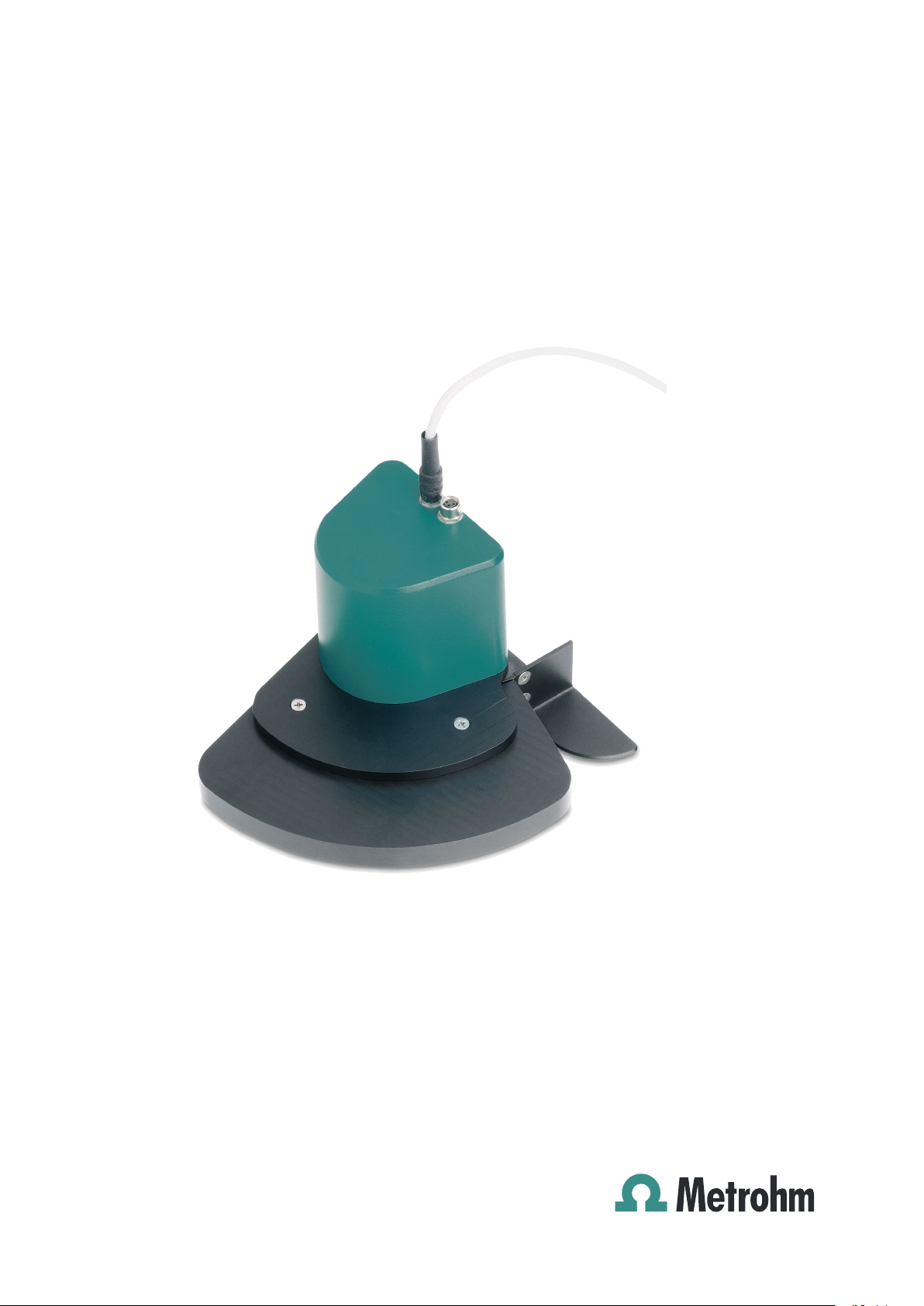
786 Swing Head
Manual
8.786.8001EN
Page 2

Page 3

Metrohm AG
CH-9101 Herisau
Switzerland
Phone +41 71 353 85 85
Fax +41 71 353 89 01
info@metrohm.com
www.metrohm.com
786 Swing Head
Manual
8.786.8001EN 01/2010 dm
Page 4

Teachware
Metrohm AG
CH-9101 Herisau
teachware@metrohm.com
This documentation is protected by copyright. All rights reserved.
Although
with great care, errors cannot be entirely excluded. Should you notice any
mistakes please send us your comments using the address given above.
all the information given in this documentation has been checked
Page 5

■■■■■■■■■■■■■■■■■■■■■■
Table of contents
Table of contents
1 Introduction
1.1 Instrument description ......................................................... 1
1.2 Model versions ...................................................................... 1
1.3 Intended use ......................................................................... 2
1.4 About the documentation ................................................... 2
1.4.1 Symbols and conventions ........................................................ 2
1.5 Safety instructions ................................................................ 3
1.5.1 General notes on safety ........................................................... 3
1.5.2 Electrical safety ........................................................................ 3
1.5.3 Tubing and capillary connections ............................................. 4
1.5.4 Personnel safety ...................................................................... 4
1.5.5 Flammable solvents and chemicals ........................................... 5
1.5.6 Recycling and disposal ............................................................. 5
1
2 Overview of the instrument 6
3 Installation 8
3.1 Packaging .............................................................................. 8
3.2 Checks .................................................................................... 8
3.3 Mounting the Swing Head to the Sample Processor ........ 8
3.3.1 Mounting the Swing Head ....................................................... 8
3.3.2 Guide chain for cables and tubing ......................................... 11
3.3.3 Mounting the robotic arm reinforcement ............................... 12
3.4 Configuring the robotic arm .............................................. 13
3.5 Mounting the robotic arm ................................................. 16
3.6 Robotic arms with beaker sensor ..................................... 18
4 Handling and maintenance 20
4.1 General ................................................................................ 20
4.2 Quality Management and validation with Metrohm ....... 20
5 Troubleshooting 21
5.1 Robotic arm ......................................................................... 21
6 Appendix 23
6.1 Robotic arms ....................................................................... 23
6.1.1 Robotic arms for titration ....................................................... 23
6.1.2 Robotic arms for sample preparation ..................................... 25
6.1.3 Robotic arms for special applications ..................................... 26
786 Swing Head
■■■■■■■■
III
Page 6

Table of contents
■■■■■■■■■■■■■■■■■■■■■■
7 Technical specifications
7.1 786 Swing Head ................................................................. 28
7.2 Supply connection .............................................................. 28
7.3 Safety specifications ........................................................... 28
7.4 Electromagnetic compatibility (EMC) ................................ 28
7.5 Ambient temperature ......................................................... 29
7.6 Reference conditions .......................................................... 29
7.7 Dimensions .......................................................................... 29
28
8 Conformity and warranty 30
8.1 Declaration of Conformity ................................................. 30
8.2 Warranty (guarantee) ......................................................... 31
8.3 Quality Management Principles ........................................ 32
9 Accessories 34
9.1 Scope of delivery 2.786.0010 ............................................ 34
9.2 Scope of delivery 2.786.0020 ............................................ 35
9.3 Scope of delivery 2.786.0030 ............................................ 36
9.4 Scope of delivery 2.786.0040 ............................................ 38
9.5 Optional accessories 2.786.0040 ...................................... 39
9.6 Scope of delivery 2.786.0240 ............................................ 40
9.7 Optional accessories 2.786.0240 ...................................... 41
Index 42
■■■■■■■■
IV
786 Swing Head
Page 7

■■■■■■■■■■■■■■■■■■■■■■
Table of figures
Figure 1 Front 786 Swing Head ...................................................................... 6
Figure 2 Underside 786 Swing Head ............................................................... 7
Figure 3 Connecting Swing Head .................................................................... 9
Figure 4 Mounting the tower extension ........................................................ 10
Figure 5 Mounting the Swing Head to the tower extension ........................... 11
Figure 6 Guide chain - Opening chain links ................................................... 12
Figure 7 Mounting the 6.2058.090 robotic arm reinforcement ..................... 13
Figure 8 Robotic arms - standard model versions: ......................................... 14
Figure 9 Configuration data of the robotic arms ............................................ 15
Figure 10 Limitation screw at the robotic arm ................................................. 16
Figure 11 Mounting the robotic arm ............................................................... 17
Figure 12 Connecting a beaker sensor (for example 6.1462.150) .................... 18
Table of figures
786 Swing Head
■■■■■■■■
V
Page 8

Page 9

■■■■■■■■■■■■■■■■■■■■■■
1 Introduction
1.1 Instrument description
The 786 Swing Head is an auxiliary drive for the Sample Processors from
Metrohm, e.g. the 815 USB Robotic Sample Processor XL. It extends the
capabilities
precisely to any given position on a sample rack. The working area of the
Sample Processors is now being expanded even further. Now, even positions
outside of the sample rack can be moved to as a result. It is thus possible to
transfer samples from the sample rack into separate working stations in just
a few simple steps.
This is a high-precision motor drive, which is mounted on the tower of a
Sample Processor. Robotic arms of different construction types are available
for assembly on the 786 Swing Head. Equipped with the corresponding
accessories, these can be used for applications requiring a high degree of
flexibility or very complex working steps.
of these automation systems to include the possibility of moving
1 Introduction
1.2 Model versions
786 Swing Head with transfer robotic arm left (2.786.0010)
Additional equipment for the Sample Processors for transferring/pipetting
liquid samples out of smaller-sized sample vessels and into larger titration
vessels on the rack or into an external titration cell which is mounted to the
left of the workplace.
786 Swing Head with transfer robotic arm right (2.786.0020)
Additional equipment for the Sample Processors for transferring/pipetting
liquid samples from smaller-sized sample vessels and into larger titration
vessels on the rack or into an external titration cell which is mounted to the
right of the workplace.
786 Swing Head with titration robotic arm (2.786.0030)
Additional equipment for the Sample Processor for the purpose of direct
titration into sample vessels 75 mL in size and larger.
786 Swing Head without robotic arm (2.786.0040)
Additional equipment for the Sample Processor without titration or transfer
robotic arm.
786 Swing Head
786 Swing Head with reinforcement right (2.786.0240)
Reinforced Swing Head for assembly on Sample Processors.
■■■■■■■■
1
Page 10
1.3 Intended use
1.3 Intended use
■■■■■■■■■■■■■■■■■■■■■■
The 786
lytical laboratories. It is not suitable for usage in biochemical, biological or
medical environments in its basic equipment version.
This instrument is suitable for transferring chemicals and flammable solvents.
The usage of the 786 Swing Head therefore requires that the user has basic
knowledge and experience in the handling of toxic and caustic substances.
Knowledge with respect to the application of the fire prevention measures
prescribed for laboratories or production plants is also mandatory.
Swing Head is designed for usage in an automation system in ana-
1.4 About the documentation
Caution
Please read through this documentation carefully before putting the
instrument
warnings which have to be followed by the user in order to ensure safe
operation of the instrument.
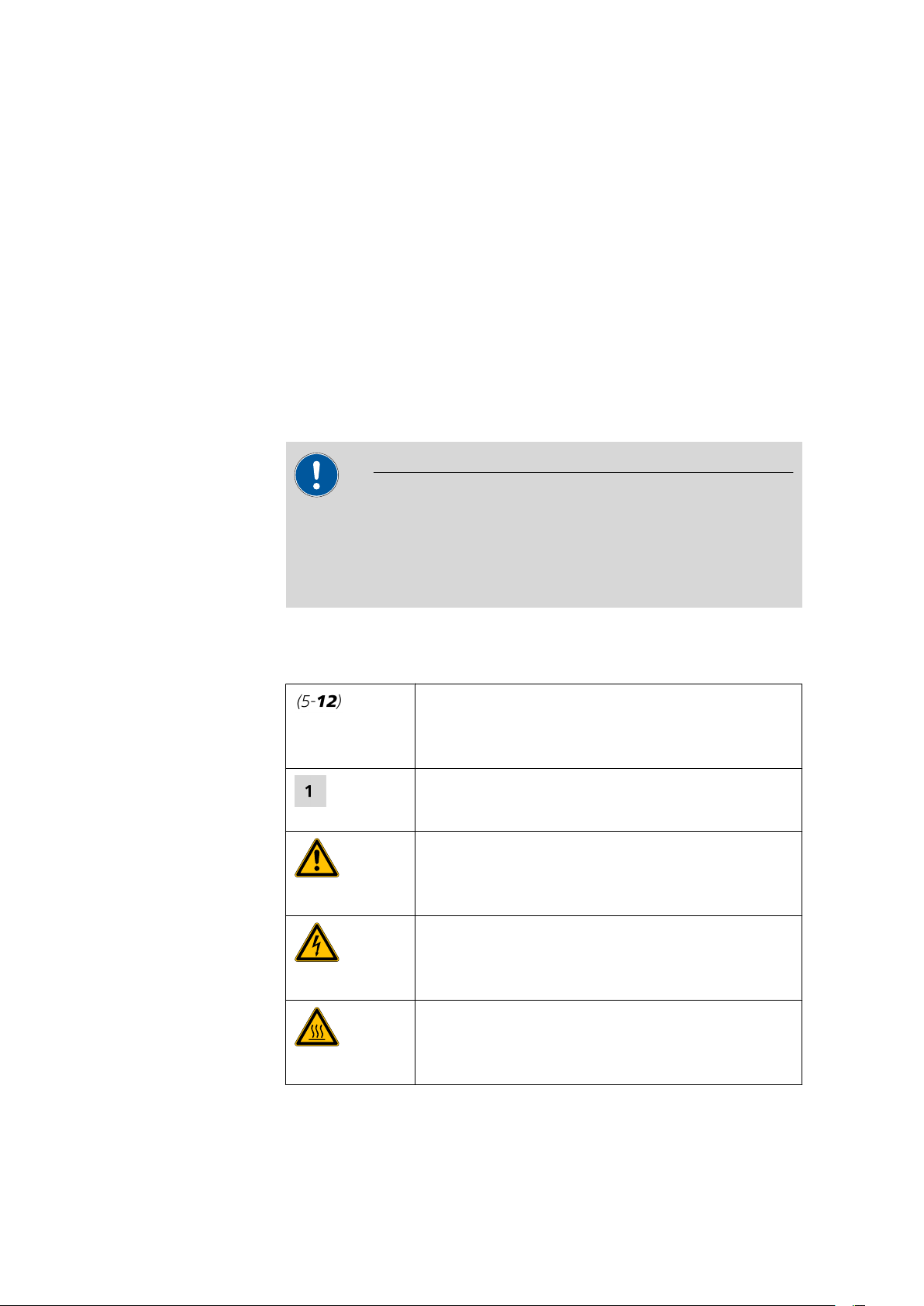
1.4.1 Symbols and conventions
The following symbols and styles are used in this documentation:
into operation. The documentation contains information and
Cross-reference to figure legend
The first number refers to the figure number, the second to the instrument part in the figure.
Instruction step
Carry out these steps in the sequence shown.
Warning
This symbol draws attention to a possible life hazard
or risk of injury.
Warning
This symbol draws attention to a possible hazard due
to electrical current.
Warning
This symbol draws attention to a possible hazard due
to heat or hot instrument parts.
■■■■■■■■
2
786 Swing Head
Page 11
■■■■■■■■■■■■■■■■■■■■■■
1.5 Safety instructions
1.5.1 General notes on safety
Warning
This instrument may only be operated in accordance with the specifications in this documentation.
1 Introduction
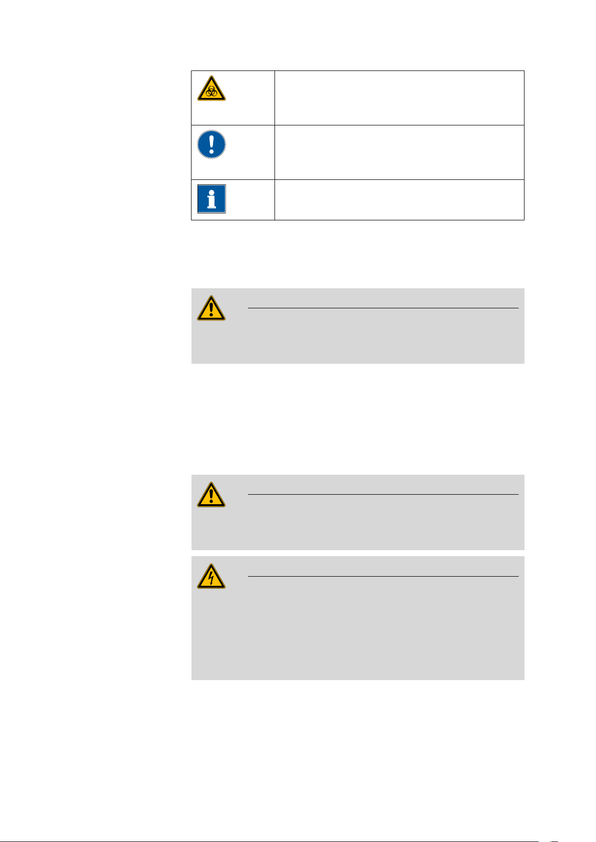
Warning
This symbol draws attention to a possible biological
hazard.
Caution
This symbol draws attention to a possible damage of
instruments or instrument parts.
Note
This symbol marks additional information and tips.
This instrument has left the factory in a flawless state in terms of technical
safety. To maintain this state and ensure non-hazardous operation of the
instrument, the following instructions must be observed carefully.
1.5.2 Electrical safety
electrical safety when working with the instrument is ensured as part of
The
the international standard IEC 61010.
Only personnel qualified by Metrohm are authorized to carry out service
work on electronic components.
Never open the housing of the instrument. The instrument could be damaged by this. There is also a risk of serious injury if live components are
touched.
There are no parts inside the housing which can be serviced or replaced
by the user.
Warning
Warning
786 Swing Head
■■■■■■■■
3
Page 12
1.5 Safety instructions
1.5.3 Tubing and capillary connections
Caution
Leaks in tubing and capillary connections are a safety risk. Tighten all
connections well by hand. Avoid applying excessive force to tubing connections. Damaged tubing ends lead to leakage. Appropriate tools can
be used to loosen connections.
Check the connections regularly for leakage. If the instrument is used
mainly
in unattended operation, then weekly inspections are mandatory.
1.5.4 Personnel safety
Warning
Wear protective goggles and working clothes suitable for laboratory work
while operating the 786 Swing Head. It is also advisable to wear gloves
when caustic liquids are used or in situations where glass vessels could
break.
■■■■■■■■■■■■■■■■■■■■■■
Warning
Always install the safety shield supplied with the equipment before using
the instrument for the first time. Pre-installed safety shields are not
allowed to be removed.
The 786 Swing Head may not be operated without a safety shield!
Warning
Personnel are not permitted to reach into the working area of the instrument while operations are running!
A considerable risk of injury exists for the user.
Warning
In the event of a possible blockage of a drive, the mains plug must be
pulled out of the socket immediately. Do not attempt to free jammed
sample vessels or other parts while the device is switched on. Blockages
can only be cleared when the instrument is in a voltage-free status; this
action generally involves a considerable risk of injury.
■■■■■■■■
4
786 Swing Head
Page 13
■■■■■■■■■■■■■■■■■■■■■■
1 Introduction
Warning
The 786
Swing Head is not suitable for utilization in biochemical, biolog-
ical or medical environments in its basic equipment version.
Appropriate protective measures must be implemented in the event that
potentially infectious samples or reagents are being processed.
1.5.5 Flammable solvents and chemicals
Warning
All relevant safety measures are to be observed when working with flammable solvents and chemicals.
■ Set up the instrument in a well-ventilated location.
■ Keep all sources of flame far from the workplace.
■ Clean up spilled liquids and solids immediately.
■ Follow the safety instructions of the chemical manufacturer.
1.5.6 Recycling and disposal
This product is covered by European Directive 2002/96/EC, WEEE – Waste
from Electrical and Electronic Equipment.
The correct disposal of your old equipment will help to prevent negative
effects on the environment and public health.
More details about the disposal of your old equipment can be obtained from
your local authorities, from waste disposal companies or from your local
dealer.
786 Swing Head
■■■■■■■■
5
Page 14
2 Overview of the instrument
1
2
3
4
5
■■■■■■■■■■■■■■■■■■■■■■
1
3
5
■■■■■■■■
6
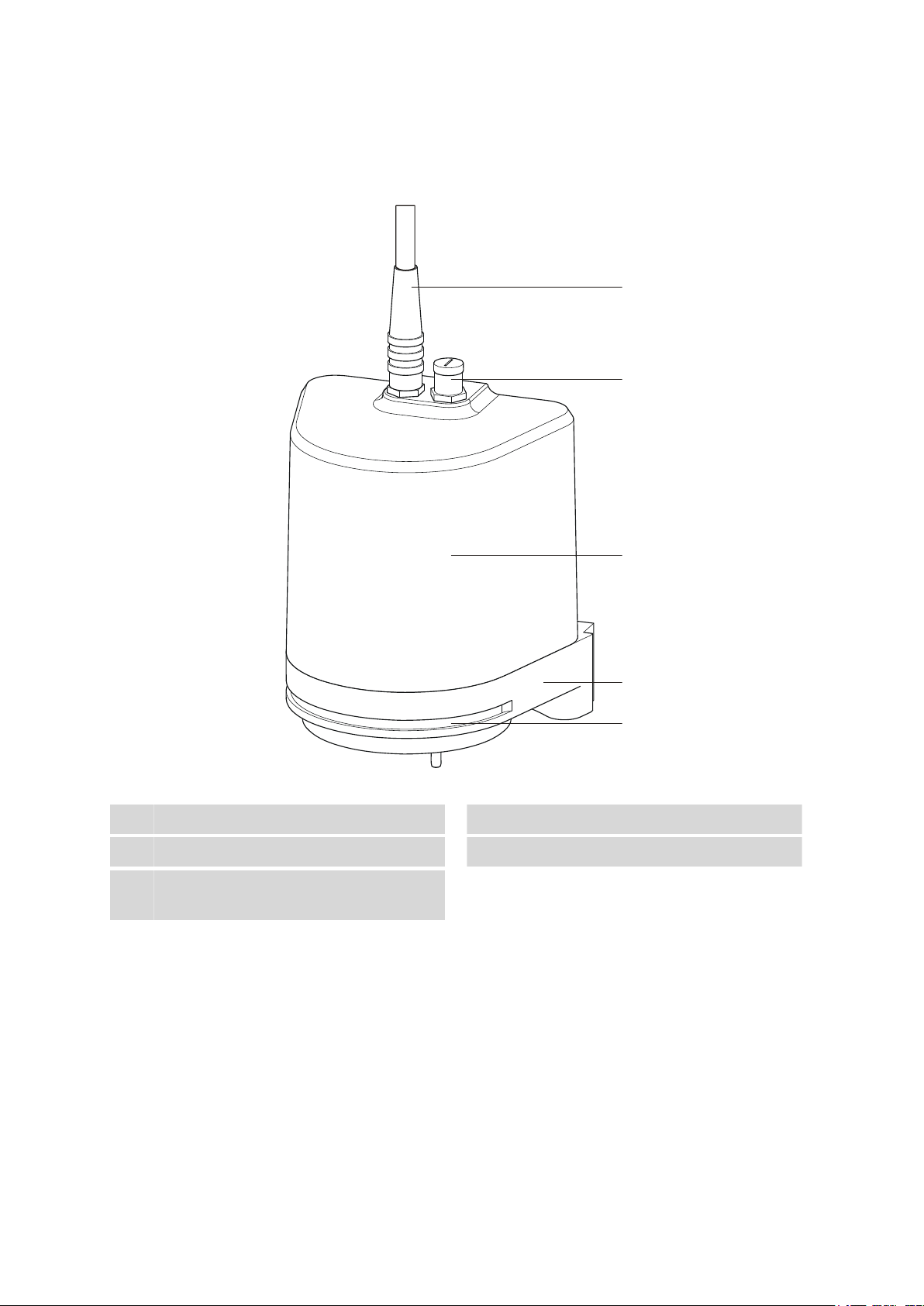
Figure 1 Front 786 Swing Head
Connection cable
Housing
Guide slot
For the robotic arm reinforcement.
Connector for beaker sensor
2
Fastening plate
4
786 Swing Head
Page 15
■■■■■■■■■■■■■■■■■■■■■■
1
2
3
3
4
2 Overview of the instrument
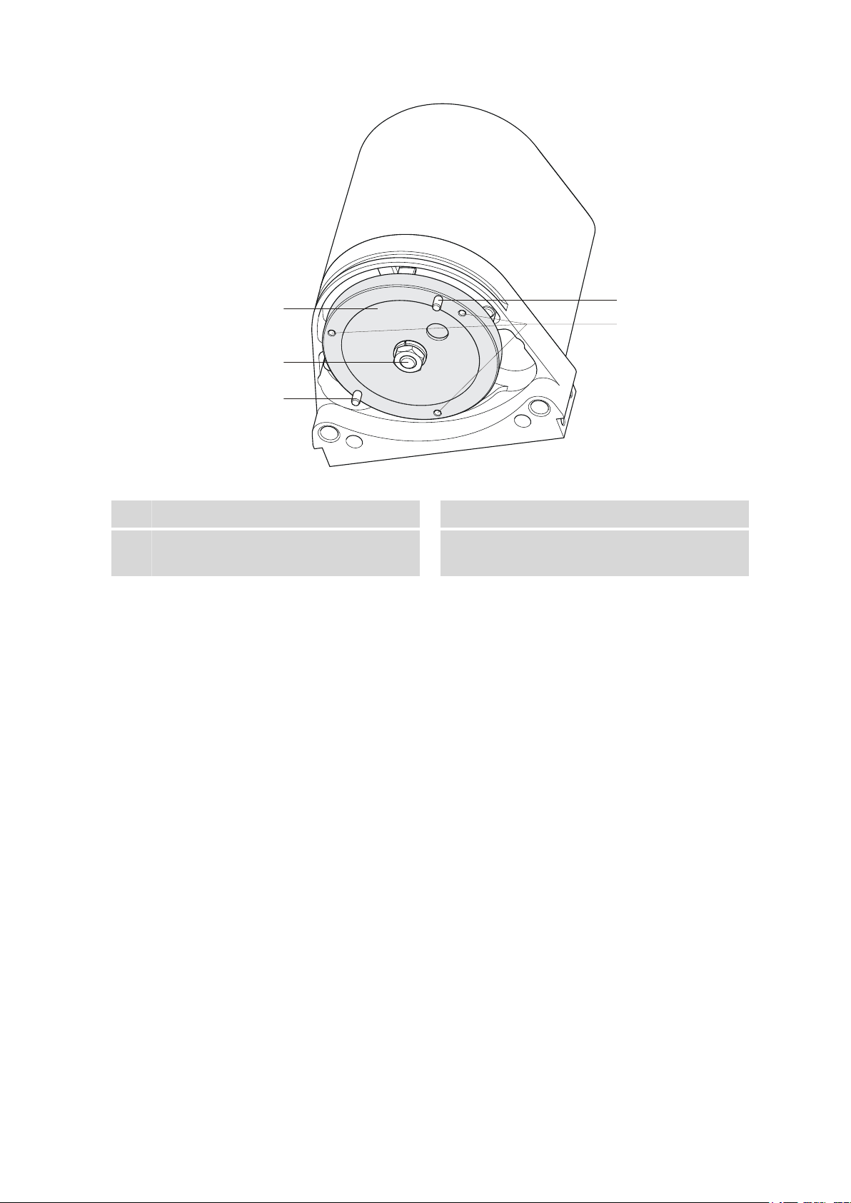
Figure 2 Underside 786 Swing Head
1
3
Drive disc
Drive pin
Swing axis
2
M2 bore holes
4
For fastening a robotic arm.
786 Swing Head
■■■■■■■■
7
Page 16

3.1 Packaging
1
1
2
3 Installation
3.1 Packaging
The instrument is supplied in highly protective special packaging together
with the separately packed accessories. Keep this packaging, as only this
ensures safe transportation of the instrument.
3.2 Checks
■■■■■■■■■■■■■■■■■■■■■■
Immediately
and without damage by comparing it with the delivery note.
after receipt, check whether the shipment has arrived complete
3.3 Mounting the Swing Head to the Sample Processor
3.3.1 Mounting the Swing Head
Dismounting the titration head holder
■■■■■■■■
8
Loosen the screws of the holder on both sides.
1
Loosen and remove the holder from the holder plate of the guide chain.
2
Use the hexagon key provided. The screws will be needed again later.
786 Swing Head
Page 17

■■■■■■■■■■■■■■■■■■■■■■
1
2
3
4
3 Installation
Connecting the Swing Head
The connection socket (Mini DIN) for the Swing Head drive is each located
on the rear of the tower next to the stirrer connector.
Figure 3 Connecting Swing Head
Connect the Swing Head as follows:
1
Plug in the cable
■ Guide the connection cable of the Swing Head through the guide
chain of the tower (see Chapter 3.3.2, page 11).
■ Plug the Mini DIN plug into the socket 'Swing Head'.
Mounting the Swing Head
Screw the Swing Head tightly to the holder plate of the guide chain.
1
Clamp the Swing Head between the guide jaws.
2
Screw the Swing Head to the guide jaws with the screws previously
3
loosened.
786 Swing Head
■■■■■■■■
9
Page 18

3.3 Mounting the Swing Head to the Sample Processor
1
Place the connection cable into the guide chain (see Chapter 3.3.2,
4
page 11).
Mounting the Swing Head with tower extension
For certain applications, it may be necessary to mount the 786 Swing
Head
at a higher position. A 6.2058.010 tower extension can be moun-
ted on the lift for this purpose.
First, remove the titration head holder from its mount (see Chapter 3.3.1,
page 8). Proceed afterwards as follows:
Fasten the tower extension to the lift guide of the Sample Processor in
1
accordance with the following illustration and fix it in place with the
screws provided.
■■■■■■■■■■■■■■■■■■■■■■
■■■■■■■■
10
Figure 4 Mounting the tower extension
Mount the Swing Head to the holder plate of the guide chain.
2
786 Swing Head
Page 19

■■■■■■■■■■■■■■■■■■■■■■
2
3
3 Installation
Figure 5 Mounting the Swing Head to the tower extension
Screw the Swing Head tightly to the upper end of the tower extension.
3
3.3.2 Guide chain for cables and tubing
Tubings and cables can be placed into the guide chain.
You can open the individual chain links with a screwdriver as follows.
1
Open the guide chain
■ Insert a screwdriver into the groove located on the side of a chain
link.
■ Loosen the clip with a forceful leverage movement.
■ Pull the clip out of the chain by hand.
■ Repeat the above actions for each chain link.
786 Swing Head
■■■■■■■■
11
Page 20

3.3 Mounting the Swing Head to the Sample Processor
Figure 6 Guide chain - Opening chain links
2
Insert into the guide chain
■ Place the required tubings or cables into the guide chain.
3
Close the guide chain
■ Close the clip for each chain link again by hand and apply forceful
pressure to snap them into place.
■■■■■■■■■■■■■■■■■■■■■■
Caution
Take care to ensure when mounting tubing and cables that there is no
traction on the drives while moving the lift or swiveling the robotic arm.
This could lead to overloading of and possible damage to the drive.
Remove
the clips of the two lowest chain links when you install the rinsing
and aspiration tubing.
3.3.3 Mounting the robotic arm reinforcement
In cases in which it is necessary to take up or strip off a filter or a pipetting
tip on the robotic arm, you must mount a 6.2058.090 robotic arm rein-
forcement. The reinforcement provides the robotic arm with stable resistance when picking up or stripping the tools used and prevents it from
bending.
The reinforcement has to be placed before mounting a robotic arm. Proceed
as follows:
■■■■■■■■
12
786 Swing Head
Page 21

■■■■■■■■■■■■■■■■■■■■■■
2
1
6.2058.090
Figure 7 Mounting the 6.2058.090 robotic arm reinforcement
Shift the reinforcement from the front over the holder plate of the
1
Swing Head.
Screw the reinforcement to the lift guide with the screws provided.
2
3 Installation
3.4 Configuring the robotic arm
A variety of differently constructed robotic arms is available for enabling a
range of applications. They differ from one another in their geometric
wide
sizes, e.g. swing radius or maximum permissible swing angle. The configuration data must be entered in the Sample Processor or in the control
software prior to the assembly of the robotic arm. The data required
is engraved on the underside of the robotic arm. Examples of the most
common robotic arms are shown in the illustration below.
786 Swing Head
■■■■■■■■
13
Page 22

3.4 Configuring the robotic arm
321
4 5
Figure 8 Robotic arms - standard model versions:
■■■■■■■■■■■■■■■■■■■■■■
Transfer robotic arm (6.1462.030)
1
For sample transfer, left-swinging.
Titration robotic arm (6.1462.050)
3
With titration head, left-/right-swinging *).
Macro robotic arm (6.1462.070)
5
With holder for a 6.1458.XXX titration head
insert, right-swinging.
*) can be mounted in two ways
A detailed list of the available robotic arms, along with the necessary
configuration data, can be found in Chapter Robotic arms, page 23ff.
The following figure illustrates the most important configuration data that
needs
to be set in the control software to ensure correct usage of a robotic
arm (left-swinging, here).
Note
Transfer robotic arm (6.1462.040)
2
For sample transfer, right-swinging.
Macro robotic arm (6.1462.060)
4
With holder for a 6.1458.XXX titration head
insert, left-swinging.
■■■■■■■■
14
786 Swing Head
Page 23

■■■■■■■■■■■■■■■■■■■■■■
2
3
4
5
1
3 Installation
Figure 9 Configuration data of the robotic arms
Swing axis
1
This runs through the middle of the Swing
Head drive.
Source axis
3
runs from the swing axis to the midpoint
This
of the sample rack and marks the initial position of the robotic arm.
Max. swing angle
5
This stands for the swing range that the
robotic arm can reach. The range runs from
the source axis to the maximum possible
robotic arm position.
Swing direction
Left-swinging (swing direction +) or right-swinging (swing direction –)
model
versions are available as different types of robotic arms. Left-swinging
Swing radius
2
is determined by the length of the robotic
This
arm. The radius runs from the axis of rotation
to the midpoint of the tip of the robotic arm.
Swing offset
4
determines the 0° position of the robotic
This
arm.
786 Swing Head
■■■■■■■■
15
Page 24

3.5 Mounting the robotic arm
1
2
means swinging from the initial position (pointing towards the middle of the
rack) outwards to the left.
In
the case of a Sample Processor with two towers, a right-swinging robotic
arm must be mounted on Tower 1, a left-swinging robotic arm on Tower 2.
If the alignment is incorrect, the two robotic arms could possibly come into
contact with one another, resulting in damage to the drives.
3.5 Mounting the robotic arm
Depending on the model, robotic arms can be mounted as either rightswinging or left-swinging. The position of the limitation screw of the robotic
arm must be taken into account during assembly. The limitation screw must
face the tower of the Sample Processor during the mounting of the robotic
arm. The following illustration shows on the left the position of the limitation
screw at a right-swinging robotic arm (Position 1) and on the right with a
left-swinging robotic arm (Position 2).
■■■■■■■■■■■■■■■■■■■■■■
Figure 10 Limitation screw at the robotic arm
For robotic arms which can be mounted in two different ways (e.g.
6.1462.050), the limitation screw can be fitted in accordance with the
required assembly direction (see above).
Note
The configuration data of a robotic arm must be configured in the control
software before it is mounted (see Chapter 3.4, page 13).
Mounting the robotic arm
The mounting of a robotic arm on the Swing Head is described here, taking
as an example a 6.1462.070 robotic arm for titration and a 6.1458.040
titration head insert. Initialize the Sample Processor before performing the
mounting sequence.
After the initialization of the Sample Processor, the drive disc of the Swing
Head
is positioned as though the robotic arm were located in the outermost
position.
16
■■■■■■■■
786 Swing Head
Page 25

■■■■■■■■■■■■■■■■■■■■■■
1
2
3
Figure 11 Mounting the robotic arm
Mount the robotic arm as follows:
Place the 6.1458.040 titration head insert in the opening of the robotic
1
arm and screw tight with the supplied screws.
Hold the robotic arm in such a way that the opening faces to the right.
2
While doing so, rotate the robotic arm outwards as far as possible,
i.e. towards the tower - see above. Slip the robotic arm from below
over the guide pins of the drive disc of the Swing Head.
3 Installation
786 Swing Head
Note
Take care to ensure that you do not twist the drive disc, thus causing
pressure against the drive.
Screw the robotic arm to the Swing Head tightly with the screws and
3
washers provided.
■■■■■■■■
17
Page 26

3.6 Robotic arms with beaker sensor
6.1462.150
1
2
3
3.6 Robotic arms with beaker sensor
For
safety reasons, the presence of a beaker on the sample rack of a Sample
Processor can be detected. Some robotic arm model versions are therefore
equipped with a beaker sensor.
■■■■■■■■■■■■■■■■■■■■■■
Figure 12 Connecting a beaker sensor (for example 6.1462.150)
Plug of the connection cable
1
Beaker sensor
3
Contact sensor in accordance with the Piezo
principle
Connection socket on the 786 Swing
2
Head
A robotic arm with beaker sensor is mounted as described on page 16. The
connection of the sensor cable must take place while the instrument is
switched off.
beaker sensor is automatically recognized when switching on the instru-
The
ment.
Functioning of the beaker sensor
If the beaker sensor of the robotic arm is activated, then the lift of the Sample
Processor will move automatically into its work position after a MOVE command. The presence of the sample vessel is checked by the robotic arm
setting down on top of it.
■■■■■■■■
18
786 Swing Head
Page 27

■■■■■■■■■■■■■■■■■■■■■■
3 Installation
No separate LIFT command is required in such cases.
Note
The work position of the lift must be configured in such a way that the
robotic arm is in place on the sample vessel. The robotic arm must bend
slightly while doing so, so that the Piezo sensor will generate a signal.
very
786 Swing Head
■■■■■■■■
19
Page 28

4.1 General
■■■■■■■■■■■■■■■■■■■■■■
4 Handling and maintenance
4.1 General
The
786 Swing Head requires appropriate care. Excess contamination of the
instrument may result in functional disruptions and a reduction in the service
life of the sturdy mechanics and electronics of the instrument.
Severe contamination can also have an influence on the measured results.
Regular cleaning of exposed parts can prevent this to a large extent.
Spilled chemicals and solvents must be removed immediately.
4.2 Quality Management and validation with Metrohm
Quality Management
Metrohm offers you comprehensive support in implementing quality management measures for instruments and software. Further information on
this can be found in the brochure «Quality Management with
Metrohm» available from your local Metrohm agent.
Validation
Please contact your local Metrohm agent for support in validating instruments and software. Here you can also obtain validation documentation to
provide help for carrying out the Installation Qualification (IQ) and the
Operational Qualification (OQ). IQ and OQ are also offered as a service
by the Metrohm agents. In addition, various application bulletins are also
available on the subject, which also contain Standard Operating Proce-
dures (SOP) for testing analytical measuring instruments for reproducibility
and correctness.
Maintenance
Electronic and mechanical functional groups in Metrohm instruments can
and should be checked as part of regular maintenance by specialist personnel from Metrohm. Please ask your local Metrohm agent regarding the
precise terms and conditions involved in concluding a corresponding maintenance agreement.
Note
You can find information on the subjects of quality management, valida-
and maintenance as well as an overview of the documents currently
tion
available at www.metrohm.com/com/ under Support.
■■■■■■■■
20
786 Swing Head
Page 29

■■■■■■■■■■■■■■■■■■■■■■
5 Troubleshooting
5.1 Robotic arm
Problem Cause Remedy
5 Troubleshooting
The robotic arm moves
all the way outward
and buzzes.
Sample Processor – The Swing
Head is not correctly configured.
Sample Processor – Robotic
arm is wrongly mounted.
1. Immediately remove the mains plug
and close the control software.
2.
Dismount the robotic arm.
3. Plug in the mains plug again and
restart the control software.
4. In the control software under "Configuration" (or under "Device manager" for Touch Control), enter the
correct value for the Swing offset.
5. Initialize the instrument.
6. Remount the robotic arm.
1. Immediately remove the mains plug
and close the control software.
Dismount the robotic arm.
2.
3. Plug in the mains plug again and
restart the control software.
4. Check the configuration of the robotic
arm and correct it if necessary (leftswinging ⇔ right-swinging).
5. Initialize the instrument.
6. Mount the robotic arm correctly.
The Swing Head either
misses the rack positions totally or is inaccurate
786 Swing Head
Sample Processor – The Swing
Head is not correctly configured.
Sample Processor – The axial
distance is not correctly configured.
Sample Processor – The wrong
rack table is being used.
1. In the control software under "Configuration" (or under "Device manager" for Touch Control), enter the
correct values for the Swing radius,
Swing offset etc.
2.
Initialize the instrument.
1. In the control software under "Configuration" (or under "Device manager" for Touch Control), enter the
correct value for the Axial distance.
2.
Initialize the instrument.
Initialize the rack using the function Ini-
tialize rack in the "Manual control".
■■■■■■■■
21
Page 30

5.1 Robotic arm
Problem Cause Remedy
■■■■■■■■■■■■■■■■■■■■■■
Swing Head – The Swing Head
drive is defective.
Contact the Metrohm Service.
■■■■■■■■
22
786 Swing Head
Page 31

■■■■■■■■■■■■■■■■■■■■■■
6.1462.050
6.1462.060
6.1462.070
6.1462.260
6 Appendix
6.1 Robotic arms
6.1.1 Robotic arms for titration
Table 1 Configuration data of the titration robotic arms
Type 6.1462.050 6.1462.060 6.1462.070 6.1462.260
6 Appendix
Swing direction +/– + – +
Swing offset 0° –8° –8° –8°
Max. swing angle 84° 73° 73° 105°
Swing radius 110 mm 127 mm 127 mm 110 mm
6.1462.050
6.1462.060
Robotic arm with titration head, left or right-swinging
For titration in 75 mL sample vessels and larger.
The arm can be equipped with two microelectrodes, one propeller stirrer
and three spray nozzles. Two buret tips with anti-diffusion valve and one
aspiration
arm.
Material: PP
Robotic arm with holder for a titration head, left-swinging
The arm can be modified to create the desired titration robotic arm by means
of the installation of a titration head 6.1458.xxx.
Material: PP
tip with connections for M6 tubing are already retracted into the
6.1462.070
786 Swing Head
Robotic arm with holder for a titration head, right-swinging
■■■■■■■■
23
Page 32

6.1 Robotic arms
6.1462.150
6.1462.160
6.1462.170
■■■■■■■■■■■■■■■■■■■■■■
The arm can be modified to create the desired titration robotic arm by means
of the installation of a titration head 6.1458.xxx.
Material: PP
6.1462.260
Robotic arm with holder for a titration head, left-swinging, external
The
arm can be modified to create the desired titration robotic arm by means
of the installation of a titration head 6.1458.xxx. The cutout permits movement to external positions near the rack, e.g. an external rinsing station.
Material: PVC
Table 2 Configuration data of the robotic arms with beaker sensor
Type 6.1462.150 6.1462.160 6.1462.170
Swing direction +/– + –
Swing offset 0° –8° –8°
Max. swing angle 84° 73° 73°
Swing radius 110 mm 127 mm 127 mm
6.1462.150
Robotic arm with titration head and beaker sensor, left or rightswinging
For titration in 75 mL sample vessels and larger.
The arm can be equipped with two microelectrodes, one propeller stirrer
and three spray nozzles. Two buret tips with anti-diffusion valve and one
aspiration
tip with connections for M6 tubing are already retracted into the
arm.
Material: PP
6.1462.160
Robotic arm with holder for a titration head and beaker sensor,
left-swinging
■■■■■■■■
24
786 Swing Head
Page 33

■■■■■■■■■■■■■■■■■■■■■■
6.1462.030
6.1462.040
6.1462.090
6.1462.240
6 Appendix
The arm can be modified to create the desired titration robotic arm by means
of the installation of a titration head 6.1458.xxx.
Material: PP
6.1462.170
Robotic arm with holder for a titration head and beaker sensor,
right-swinging
The
arm can be modified to create the desired titration robotic arm by means
of the installation of a titration head 6.1458.xxx.
Material: PP
6.1.2 Robotic arms for sample preparation
Table 3 Configuration data of the robotic arms for sample preparation
Type 6.1462.030 6.1462.040 6.1462.090 6.1462.240
Swing direction + – – –
Swing offset 8° 8° 8° –8.6°
Max. swing angle 117° 117° 117° 122°
Swing radius 112 mm 112 mm 112 mm 149.8 mm
6.1462.030
Robotic arm with transfer head, left-swinging
Robotic
arm for fully automated pipetting or dilution of liquid samples with
Sample Processor Systems.
Material: PP
6.1462.040
Robotic arm with transfer head, right-swinging
Robotic arm for fully automated pipetting or dilution of liquid samples with
Sample Processor Systems.
Material: PP
6.1462.090
Robotic arm with Luer lock adapter, right-swinging
For the connection of hollow needles with Luer lock connection. Suitable
for the transfer of samples from sealed vials with septum seal.
Material: PP
786 Swing Head
■■■■■■■■
25
Page 34

6.1 Robotic arms
6.1462.250
6.1462.080
■■■■■■■■■■■■■■■■■■■■■■
6.1462.240
Robotic arm with transfer head, bent, right-swinging
The transfer head can, when equipped with 6.1808.220 adapter, be used
as a holder for various tools with Luer connection on multirow racks.
Material: PP
6.1.3 Robotic arms for special applications
Table 4 Configuration data of the special robotic arms
Type 6.1462.250 6.1462.080
Swing direction + +
Swing offset 0° 8°
Max. swing angle 115.5° 117°
Swing radius 110 mm 112 mm
6.1462.250
Robotic arm as holder for a Polytron, left-swinging
The
robotic arm makes it possible to use the Polytron for sample preparation
on multirow sample racks. It contains one retracted buret tip for adding
solvents and three spray nozzles for cleaning.
Material: PP
6.1462.080
Robotic arm DIS-COVER, left-swinging
■■■■■■■■
26
786 Swing Head
Page 35

■■■■■■■■■■■■■■■■■■■■■■
6 Appendix
Robotic arm for placing and removing sample vessel covers (75 and 250 mL)
covers
6.2037.050 und 6.2037.060) on the sample rack of a Robotic Sample
Processor.
Material: PP
786 Swing Head
■■■■■■■■
27
Page 36

7.1 786 Swing Head
7 Technical specifications
7.1 786 Swing Head
■■■■■■■■■■■■■■■■■■■■■■
Load
Rate
Beaker sensor
Approx. 15 N
10…55 angular degree/s
For the robotic arm with sensor
socket
7.2 Supply connection
Connector plug
9-pin Mini DIN plug
For connecting to a Sample Processor (Swing Head socket)
7.3 Safety specifications
Design and testing
Safety instructions
According to EN/IEC/UL 61010-1, EN/IEC 61010-2-081, CSA-C22.2 No.
61010-1, protection class ⅠⅠⅠ
This document contains safety instructions which have to be followed by
the user in order to ensure safe operation of the instrument.
7.4 Electromagnetic compatibility (EMC)
Emission
Immunity
■■■■■■■■
28
Standards fulfilled
■ EN/IEC 61326-1
■ EN/IEC 61000-6-3
■ EN 55022 / CISPR 22
■ EN/IEC 61000-3-2
Standards fulfilled
■ EN/IEC 61326-1
■ EN/IEC 61000-6-2
■ EN/IEC 61000-4-2
■ EN/IEC 61000-4-3
■ EN/IEC 61000-4-4
■ EN/IEC 61000-4-5
■ EN/IEC 61000-4-6
■ EN/IEC 61000-4-8
■ EN/IEC 61000-4-11
■ EN/IEC 61000-4-14
■ NAMUR
786 Swing Head
Page 37

■■■■■■■■■■■■■■■■■■■■■■
7.5 Ambient temperature
7 Technical specifications
Nominal function
range
Storage
Transport
5…45 °C
Humidity < 80 %
–20…60 °C
–40…60 °C
7.6 Reference conditions
Ambient temperature
Relative humidity
25 °C (±3 °C)
≤60 %
7.7 Dimensions
Width
Height
Depth
Weight (without
accessories)
0.10 m
0.15 m
0.09 m
0.97 kg
Material
Housing
Metal housing, surface-treated
786 Swing Head
■■■■■■■■
29
Page 38

8.1 Declaration of Conformity
8 Conformity and warranty
8.1 Declaration of Conformity
This is to certify the conformity to the standard specifications for electrical
appliances and accessories, as well as to the standard specifications for
security and to system validation issued by the manufacturing company.
■■■■■■■■■■■■■■■■■■■■■■
Name of commodity
Electromagnetic compatibility
786 Swing Head
The
786 Swing Head is a motor drive for robotic arms which can be used
with Metrohm Sample Processors.
This instrument has been built and has undergone final type testing according to the standards:
Emission: EN/IEC 61326-1: 2002, EN/IEC 61000-6-3: 2001,
EN 55022 / CISPR 22: 2006
EN/IEC 61000-3-2: 2000
Immunity: EN/IEC 61326-1: 2002, EN/IEC 61000-6-2: 2001,
EN/IEC 61000-4-2: 2001,
EN/IEC 61000-4-3: 2002,
EN/IEC 61000-4-4: 2004,
EN/IEC 61000-4-5: 2001,
EN/IEC 61000-4-6: 2001,
EN/IEC 61000-4-8: 2001,
EN/IEC 61000-4-11: 2004,
EN/IEC 61000-4-14: 2004, NAMUR: 2004
,
Safety specifications
■■■■■■■■
30
EN/IEC 61010-1, protection class III
This instrument meets the requirements of the CE mark as contained in the
EU directives
specifications:
EN 61326-1 Electrical equipment for measurement, control and
EN 61010-1 Safety requirements for electrical equipment for
EN 61010-2-081 Particular requirements for automatic and semi-
2006/95/EC (LVD), 2004/108/EC (EMC). It fulfils the following
laboratory use – EMC requirements
measurement, control and laboratory use
automatic laboratory equipment for analysis and
other purposes
786 Swing Head
Page 39

■■■■■■■■■■■■■■■■■■■■■■
8 Conformity and warranty
Manufacturer
Metrohm Ltd., CH-9101 Herisau/Switzerland
Metrohm Ltd. is holder of the SQS certificate ISO 9001:2000 Quality management
system for development, production and sales of instruments and
accessories for ion analysis.
Herisau, 31 March, 2003
D. Strohm
Vice President, Head of R&D
8.2 Warranty (guarantee)
Metrohm
material, design or manufacturing errors. The warranty period is 36 months
from the day of delivery; for day and night operation it is 18 months. The
warranty remains valid on condition that the service is provided by an
authorized Metrohm service organization.
guarantees that the deliveries and services it provides are free from
A. Dellenbach
Head of Quality Management
Glass breakage is excluded from the warranty for electrodes and other
glassware. The warranty for the accuracy corresponds to the technical specifications given in this manual. For components from third parties that make
up a considerable part of our instrument, the manufacturer's warranty provisions apply. Warranty claims cannot be pursued if the Customer has not
complied with the obligations to make payment on time.
During the warranty period Metrohm undertakes, at its own choice, to either
repair at its own premises, free of charge, any instruments that can be shown
to be faulty or to replace them. Transport costs are to the Customer's
account.
Faults arising from circumstances that are not the responsibility of Metrohm,
such as improper storage or improper use, etc. are expressly excluded from
the warranty.
786 Swing Head
■■■■■■■■
31
Page 40

8.3 Quality Management Principles
8.3 Quality Management Principles
Metrohm Ltd. holds the ISO 9001:2000 Certificate, registration number
10872-02, issued by SQS (Swiss Association for Quality and Management
Systems). Internal and external audits are carried out periodically to assure
that the standards defined by Metrohm’s QM Manual are maintained.
The steps involved in the design, manufacture and servicing of instruments
are fully documented and the resulting reports are archived for ten years.
The development of software for PCs and instruments is also duly documented
possession of Metrohm. A non-disclosure agreement may be asked to be
provided by those requiring access to them.
The implementation of the ISO 9001:2000 quality management system is
described in Metrohm’s QM Manual, which comprises detailed instructions
on the following fields of activity:
Instrument development
The organization of the instrument design, its planning and the intermediate
controls are fully documented and traceable. Laboratory testing accompanies all phases of instrument development.
and the documents and source codes are archived. Both remain the
■■■■■■■■■■■■■■■■■■■■■■
Software development
Software development occurs in terms of the software life cycle. Tests are
performed to detect programming errors and to assess the program’s functionality in a laboratory environment.
Components
All components used in the Metrohm instruments have to satisfy the quality
standards that are defined and implemented for our products. Suppliers of
components are audited by Metrohm as the need arises.
Manufacture
The measures put into practice in the production of our instruments guarantee a constant quality standard. Production planning and manufacturing
procedures, maintenance of production means and testing of components,
intermediate and finished products are prescribed.
Customer support and service
Customer support involves all phases of instrument acquisition and use by
the customer, i.e. consulting to define the adequate equipment for the analytical problem at hand, delivery of the equipment, user manuals, training,
after-sales service and processing of customer complaints. The Metrohm
service organization is equipped to support customers in implementing
standards such as GLP, GMP, ISO 900X, in performing Operational Qualifi-
■■■■■■■■
32
786 Swing Head
Page 41

■■■■■■■■■■■■■■■■■■■■■■
8 Conformity and warranty
cation and Performance Verification of the system components or in carrying
out
the System Validation for the quantitative determination of a substance
in a given matrix.
786 Swing Head
■■■■■■■■
33
Page 42

9.1 Scope of delivery 2.786.0010
9 Accessories
Note
Subject to change without notice.
9.1 Scope of delivery 2.786.0010
Qty. Order no. Description
1 1.786.0010 786 Swing Head
Additional drive for a Sample Processor required for the usage of a
robotic arm.
■■■■■■■■■■■■■■■■■■■■■■
1 6.1462.030 Robotic arm with transfer head for 786
Swing Head, left swinging
Transfer robotic arm for liquid handling purposes
Material: PP (black)
1 6.1562.100 Pipetting tubing / 10 mL
Pipetting tubing for fully automated liquid transfer.
Material: FEP
Length (m): 3.8
Volume (mL): 10
1 6.1823.010 Guiding shaft to Pipetting tubing
Used with the Transfer Arm of the Robotic Sample Processor
Outer diameter (mm): 6
Length (mm): 163
■■■■■■■■
34
786 Swing Head
Page 43

■■■■■■■■■■■■■■■■■■■■■■
Qty. Order no. Description
1 6.2621.120 Hexagon key 1.5 mm
2 V.024.4012 Counter sunk screw
1 8.786.8001EN 786 Swing Head Manual
9.2 Scope of delivery 2.786.0020
9 Accessories
Qty. Order no. Description
1 1.786.0010 786 Swing Head
Additional drive for a Sample Processor required for the usage of a
robotic arm.
1 6.1462.040 Robotic arm with transfer head for 786
Swing Head, right swinging
Transfer robotic arm for liquid handling purposes
Material: PP (black)
1 6.1562.100 Pipetting tubing / 10 mL
Pipetting tubing for fully automated liquid transfer.
Material: FEP
Length (m): 3.8
Volume (mL): 10
786 Swing Head
■■■■■■■■
35
Page 44

9.3 Scope of delivery 2.786.0030
Qty. Order no. Description
1 6.1823.010 Guiding shaft to Pipetting tubing
Used with the Transfer Arm of the Robotic Sample Processor
Outer diameter (mm): 6
Length (mm): 163
1 6.2621.120 Hexagon key 1.5 mm
■■■■■■■■■■■■■■■■■■■■■■
2 V.024.4012 Counter sunk screw
1 8.786.8001EN 786 Swing Head Manual
9.3 Scope of delivery 2.786.0030
Qty. Order no. Description
1 1.786.0010 786 Swing Head
Additional drive for a Sample Processor required for the usage of a
robotic arm.
■■■■■■■■
36
786 Swing Head
Page 45

■■■■■■■■■■■■■■■■■■■■■■
Qty. Order no. Description
1 6.1462.050 Robotic arm with titration head for 786
Swing Head, left or right swinging
Titration head for Swing Head
Material: PP (black)
1 6.1808.040 Thread adapter M6 outer / M8 inner
Outer thread M6, inner thread M8.
Material: PTCFE
9 Accessories
1 6.1909.030 Stirring propeller / 104 mm
Propeller stirrer with PP shaft, PVDF tip. Length from the SGJ: 104 mm.
For KF applications with 722, 802 Rod Stirrer
Material: PP
2 6.2042.030 Buret tip clip (rod stirrer)
Clip for proper alignment of buret tips, dosing or aspiration tubings
using a rod stirrer in the titration beaker of a sample changer
Material: PEEK
786 Swing Head
■■■■■■■■
37
Page 46

9.4 Scope of delivery 2.786.0040
Qty. Order no. Description
1 6.2621.120 Hexagon key 1.5 mm
2 V.024.4012 Counter sunk screw
1 8.786.8001EN 786 Swing Head Manual
9.4 Scope of delivery 2.786.0040
■■■■■■■■■■■■■■■■■■■■■■
Qty. Order no. Description
1 1.786.0010 786 Swing Head
Additional drive for a Sample Processor required for the usage of a
robotic arm.
1 6.2621.120 Hexagon key 1.5 mm
2 V.024.4012 Counter sunk screw
1 8.786.8001EN 786 Swing Head Manual
■■■■■■■■
38
786 Swing Head
Page 47

■■■■■■■■■■■■■■■■■■■■■■
9.5 Optional accessories 2.786.0040
Order no. Description
6.1462.240 Transfer head for 786 Swing Head, bent and right
swinging
Transfer head, bent and right swinging, for 786 Swing Head. In combination with
the
6.1808.220 Adapter the transfer head can be used on multi-row racks to pick
up tools with luer connection.
Material: PP (black)
9 Accessories
6.1462.250
Swing arm for Polytron and 786 Swing Head, left swinging, with one buret tip for
the
additiona of solvent or titrant and three spray nozzles for cleaning. The swing
arm allows the usage of the Polytron for sample preparation on multi row racks.
Material: PP (black)
Material 2: Metal
6.1462.260
Titration head holder to 786 Swing Head with possibility to swing to external
positions
Material: PVC
Swing arm for Polytron and 786 Swing Head, left
swinging
Robotic arm with holder for titration head, left swinging, external
786 Swing Head
■■■■■■■■
39
Page 48

9.6 Scope of delivery 2.786.0240
Order no. Description
6.2058.040 Swing arm enhancement for Swing Head 786
The swing arm enhancement is for stabilizing the swing arm connected to the 786
Swing Head and working with various tools
Material: Aluminum
9.6 Scope of delivery 2.786.0240
Qty. Order no. Description
1 1.786.0110 786 Swing Head
■■■■■■■■■■■■■■■■■■■■■■
Additional drive for a Sample Processor required for the usage of a
robotic arm.
1 6.2058.090 Verstärkung zu SwingHead R
1 6.2621.120 Hexagon key 1.5 mm
2 V.024.4012 Counter sunk screw
1 8.786.8001EN 786 Swing Head Manual
■■■■■■■■
40
786 Swing Head
Page 49

■■■■■■■■■■■■■■■■■■■■■■
9.7 Optional accessories 2.786.0240
Order no. Description
6.1462.240 Transfer head for 786 Swing Head, bent and right
swinging
Transfer head, bent and right swinging, for 786 Swing Head. In combination with
the
6.1808.220 Adapter the transfer head can be used on multi-row racks to pick
up tools with luer connection.
Material: PP (black)
9 Accessories
786 Swing Head
■■■■■■■■
41
Page 50

Index
Index
■■■■■■■■■■■■■■■■■■■■■■
B
Beaker sensor ..................... 18, 24
D
DIS-COVER ............................... 26
Drive disc ............................. 7, 16
Drive pin .................................... 7
G
GLP .......................................... 20
Guarantee ................................ 31
Guide chain ........................ 10, 11
Guide pins ................................ 17
L
Left-swinging. .......................... 14
Limitation screw ....................... 16
Luer lock adapter ..................... 25
M
Max. swing angle ..................... 15
Mini DIN .................................... 9
Model versions ........................... 1
P
Polytron ................................... 26
Q
Quality Management ................ 20
R
Right-swinging.. ....................... 14
Robotic arm
Beaker sensor ............... 18, 24
Bent ................................... 26
Configuration data
......................... 14, 23, 25, 26
Configuring ........................ 13
Left-swinging ..................... 15
Luer lock adapter ................
Model versions ............. 13, 23
Mounting ........................... 16
Right-swinging ................... 15
Titration head ..................... 23
Transfer head ..................... 25
Robotic arm reinforcement ....... 12
Robotic arms
Model versions ................... 25
S
Safety instructions ...................... 3
Sample preparation .................. 25
25
Service ....................................... 3
Service Agreement ................... 20
Swing axis ............................ 7, 15
Swing direction ........................ 15
Swing Head
Connect ............................... 9
Mounting ............................. 9
Swing offset ............................. 15
Swing radius ............................ 15
T
Titration head ........................... 23
Titration head holder .................. 8
Tower extension ....................... 10
Transfer head ........................... 25
Troubleshooting ....................... 21
V
Validation ................................. 20
W
Warranty .................................. 31
■■■■■■■■
42
786 Swing Head
 Loading...