

Marantz PS-2100 Service Manual
Service
PS2100/N1S, /C1S
Manual
STANDBY
STANDBY
1. TECHNICAL SPECIFICATIONS .............................................................................1
2. SERVICE MODE ....................................................................................................2
3. TUNER ADJUSTMENT...........................................................................................3
4. DLOCK DIAGRAM..................................................................................................5
5. SCHEMATIC DIAGRAM AND PARTS LOCATION .................................................7
6. MICROPROCESSOR AND IC DATA ....................................................................29
7. SODA (Self-Oscillating class D Amplifier) .............................................................36
8. EXPLODED VIEW AND PARTS LIST...................................................................37
9. ELECTRICAL PARTS LIST...................................................................................40
AV Receiver
OPEN/CLOSE
PS2100
OPEN/CLOSE
(PUSH ENTER)
DISPLAY
SURROUND
PHONES
TUNER
MEMORY
BAND
TIMER
MULTI JOG
AMP
TABLE OF CONTENTS
VOLUME
-
+
Please use this service manual with referring to the user guide (D.F.U) without fail.
PS2100
PS2100
328J855010 AO
3120 785 22660
First Issue:2001.05
MARANTZ DESIGN AND SERVICE
Using superior design and selected high grade components, MARANTZ company has created the ultimate in stereo sound.
Only original
it is famous.
Parts for your
ORDERING PARTS :
Parts can be ordered either by mail or by Fax.. In both cases, the correct part number has to be specified.
The following information must be supplied to eliminate delays in processing your order :
1. Complete address
2. Complete part numbers and quantities required
3. Description of parts
4. Model number for which part is required
5. Way of shipment
6. Signature : any order form or Fax. must be signed, otherwise such part order will be considered as null and void.
MARANTZ parts can insure that your MARANTZ product will continue to perform to the specifications for which
MARANTZ equipment are generally available to our National Marantz Subsidiary or Agent.
USA
MARANTZ AMERICA, INCMARANTZ AMERICA, INC.
440 MEDINAH ROAD
ROSELLE, ILLINOIS 60172
USA
PHONE : 630 - 307 - 3100
FAX : 630 - 307 - 2687
AMERICAS
SUPERSCOPE TECHNOLOGIES, INC.
MARANTZ PROFESSIONAL PRODUCTS
2640 WHITE OAK CIRCLE, SUITE A
AURORA, ILLINOIS 60504 USA
PHONE : 630 - 820 - 4800
FAX : 630 - 820 - 8103
AUSTRALIA
QualiFi Pty Ltd,
24 LIONEL ROAD,
MT. WAVERLEY VIC 3149
AUSTRALIA
PHONE : +61 - (0)3 - 9543 - 1522
FAX : +61 - (0)3 - 9543 - 3677
NEW ZEALAND
WILDASH AUDIO SYSTEMS NZ
14 MALVERN ROAD MT ALBERT
AUCKLAND NEW ZEALAND
PHONE : +64 - 9 - 8451958
FAX : +64 - 9 - 8463554
EUROPE / TRADING
MARANTZ EUROPE B.V.
P.O.BOX 80002, BUILDING SFF2
5600 JB EINDHOVEN
THE NETHERLANDS
PHONE : +31 - 40 - 2732241
FAX : +31 - 40 - 2735578
AUSTRALIA
TECHNICAL AUDIO GROUP PTY, LTD
558 DARLING STREET,
BALMAIN, NSW 2041,
AUSTRALIA
PHONE : 61 - 2 - 9810 - 5300
FAX : 61 - 2 - 9810 - 5355
THAILAND
MRZ STANDARD CO.,LTD
746 - 754 MAHACHAI ROAD.,
WANGBURAPAPIROM, PHRANAKORN,
BANGKOK, 10200 THAILAND
PHONE : +66 - 2 - 222 9181
FAX : +66 - 2 - 224 6795
TAIWAN
PAI- YUING CO., LTD.
6 TH FL NO, 148 SUNG KIANG ROAD,
TAIPEI, 10429, TAIWAN R.O.C.
PHONE : +886 - 2 - 25221304
FAX : +886 - 2 - 25630415
BRAZIL
PHILIPS DA AMAZONIA IND. ELET. ITDA
CENTRO DE INFORMACOES AO
CEP 04698-970
SAO PAULO, SP, BRAZIL
PHONE : 0800 - 123123
FAX : +55 11 534. 8988
(Discagem Direta Gratuita)
CANADA
LENBROOK INDUSTRIES LIMITED
633 GRANITE COURT,
PICKERING, ONTARIO L1W 3K1
CANADA
PHONE : 905 - 831 - 6333
FAX : 905 - 831 - 6936
SINGAPORE
WO KEE HONG DISTRIBUTION PTE LTD
130 JOO SENG ROAD
#03-02 OLIVINE BUILDING
SINGAPORE 368357
PHONE : +65 858 5535 / +65 381 8621
FAX : +65 858 6078
MALAYSIA
WO KEE HONG ELECTRONICS SDN. BHD.
SUITE 8.1, LEVEL 8, MENARA GENESIS,
NO. 33, JALAN SULTAN ISMAIL,
50250 KUALA LUMPUR, MALAYSIA
PHONE : +60 3 - 2457677
FAX : +60 3 - 2458180
JAPAN
MARANTZ JAPAN, INC.
35- 1, 7- CHOME, SAGAMIONO
SAGAMIHARA - SHI, KANAGAWA
JAPAN 228-8505
PHONE : +81 42 748 1013
FAX : +81 42 741 9190
Technical
KOREA
MK ENTERPRISES LTD.
ROOM 604/605, ELECTRO-OFFICETEL, 16-58,
3GA, HANGANG-RO, YONGSAN-KU, SEOUL
KOREA
PHONE : +822 - 3232 - 155
FAX : +822 - 3232 - 154
SHOCK, FIRE HAZARD SERVICE TEST :
CAUTION : After servicing this appliance and prior to returning to customer, measure the resistance between either primary AC
cord connector pins ( with unit NOT connected to AC mains and its Power switch ON ), and the face or Front Panel of product and
controls and chassis bottom.
Any resistance measurement less than 1 Megohms should cause unit to be repaired or corrected before AC power is applied, and
verified before it is return to the user/customer.
Ref. UL Standard No. 1492.
In case of difficulties, do not hesitate to contact the Technical
Department at above mentioned address.
001120 A.O

1. TECHNICAL SPECIFICATIONS
FM TUNER SECTION
Frequency Range........................................................................................................................................... 87.5 - 108.0 MHz
Usable Sensitivity ...................................................................................................................................... IHF 1.8 V / 16.4 dBf
Signal to Noise Ratio........................................................................................................................ Mono / Stereo 75 / 68 dB
Distortion .......................................................................................................................................... Mono / Stereo 0.2 / 0.5 %
Stereo Separation .............................................................................................................................................. 45 dB at 1 kHz
Alternate Channel Selectivity ........................................................................................................................ 60 dB ( 300 kHz)
AM TUNER SECTION
Frequency Range............................................................................................................................................... 531 - 1602 kHz
Signal to Noise Ratio......................................................................................................................................................... 50 dB
Usable Sensitivity ................................................................................................................................................... Loop 400 V
Distortion ........................................................................................................................................... 400 Hz, 30 % Mod. 0.5 %
Selectivity ........................................................................................................................................................... 18 kHz 40 dB
AUDIO SECTION
Rated Output Power (5 channel drive)............................................................................................................ 30 W at 8 ohms load
Stereo mode ................................................................................................................................................................ 50 W + 50 W
Input Sensitivity/Impedance ............................................................................................................................... 300 mV / 47 k ohm
Video Selector
Input, Output Level/Impedance............................................................................................................................ 1.0 Vp-p / 75 ohm
GENERAL
Power Supply ......................................................................................................................................
Power Consumption ........................................................................................................................................................ 280 W
Dimension (MAX)
Width........................................................................................................................................................................ 420 mm
Height ........................................................................................................................................................................ 76 mm
Depth ....................................................................................................................................................................... 322 mm
Weight........................................................................................................................................................................ 5.5 Kg
AC 220 V 60 Hz - C1S
AC 230 V 50 Hz - N1S
ACCESSORIES
Remote Control Unit RC2100SR............................................................................................................................................... 1
AAA-size batteries.................................................................................................................................................................... 2
FM Feeder Antenna .................................................................................................................................................................. 1
AM Loop Antenna...................................................................................................................................................................... 1
Bus cable...................................................................................................................................................................................1
AC cord .....................................................................................................................................................................................1
Specifications subject to change without prior notice.
1
2. SERVICE MODE
1.Trucking point memory of present memo ry / LCD segment luminous / check of speaker output
C onnec t a n AC ca b le p lug t o m ai n s w hil e p r es s ing < DIS PL AY> and < EN TE R> .
: Press <ENTER>, or Automatically to go
SERVICE
VER xxxx
PUSH ENTER
LCD TEST
VER xxxx
<ENTER>
All p ar ts of
Turned on
Segm ent
displayed
one by one
LCD is
Each
is
AUX
Turn J OG
AUTO
TUNER
FM 87.50
MHz
Turn J OG
DVD
Turn J OG
LD/VCR
Turn J OG
<DISPLAY>
and
<ENTER>
<ENTER>
5sec.
Vers ion o f
MAIN u-com
is displayed.
PUSH ENTER
TR FREQ
VER xxxx
PRESET
FM 87.50
MHz
5sec.
M01 AUTO
PRESET1
FM 87.50
MHz
Turn J OG
Turn J OG
5sec.
CLEAR
VER xxxx
AUTO
<ENTER>
<ENTER>
PUSH ENTER
VER xxxx
<DISPLAY>
and
<ENTER>
M02 AUTO
FM 90.10
M10
AM 1620
M01 AUTO
FM 87.50
: Pre ss <DISPL AY> and <ENTER >
: Turn JOG
: Only first time to go
<
DISPLAY>
<ENTER>
PUSH ENTER
TONE
EXIT
VER xxxx
LF NOISE
<ENTER>
ALL MUTE
<DISPLAY>
and
<ENTER>
CENTER
ALL MUTE
M02
MHz
Turn J OG
M10
kHz
RF NOISE
ALL MUTE
RS NOISE
ALL MUTE
Tur n J OG
LS NOISE
M01
MHz
ALL MUTE
Shu t down the power.
and
OFF
2sec.
1sec.
2sec.
1sec.
2sec.
1sec.
2sec.
1sec.
2sec .
1sec .
TV
Turn J OG
VCR
BAND M01 M02 M03 M04 M05 M06 M07 M08 M09 M10
FM
[MHz]
AM
[kHz]
87.50 90.10 100.10 106.10 108.00 --- --- --- --- ---
--- --- --- --- --- 552 612 999 1503 1620
2
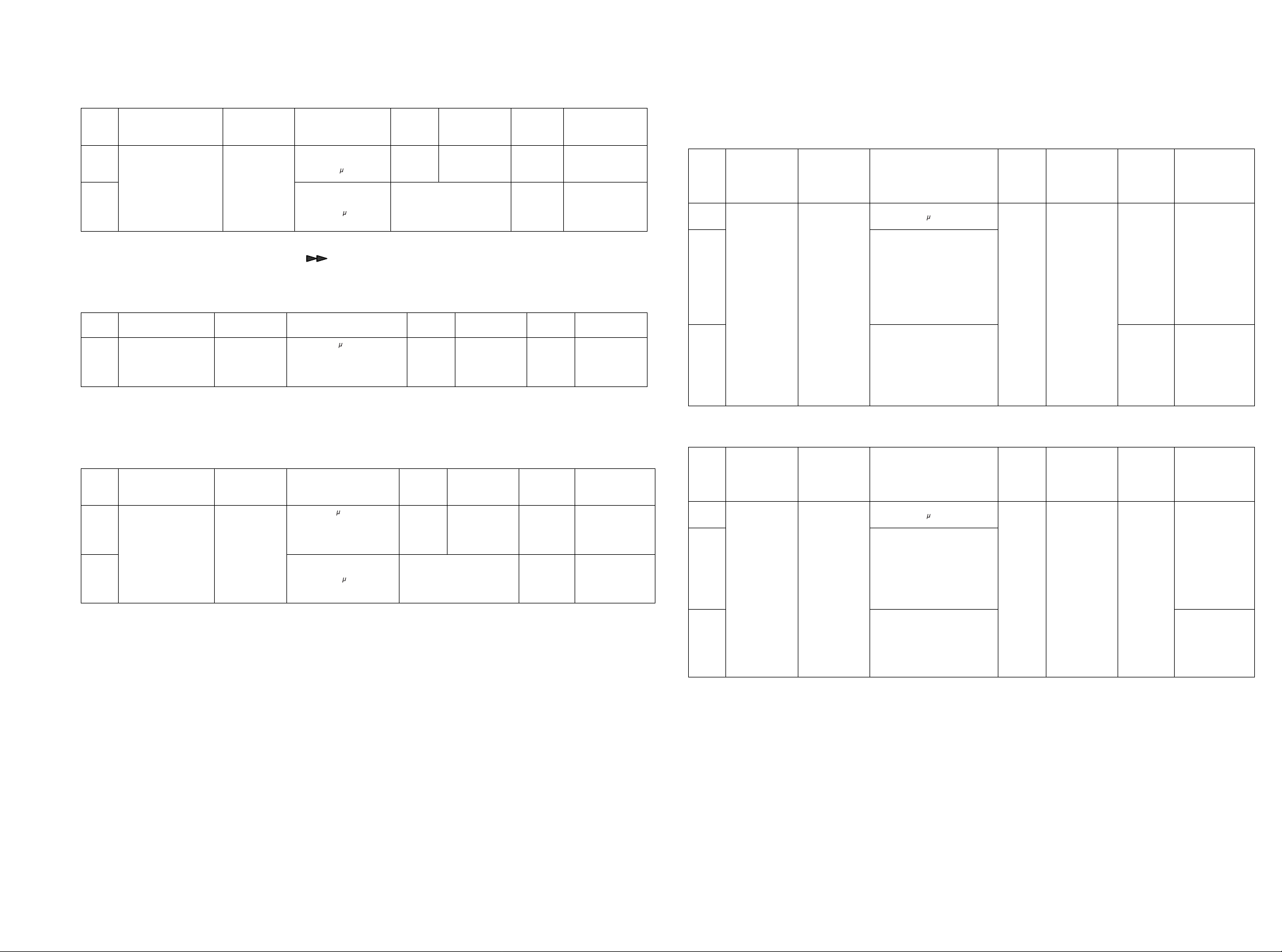
3. TUNER ADJUSTMENT
1. AM auto stop Level Check
Step
1
2
*Set RA11 first TUNED OFF (disappear TUNED) and 2nd set to TUNED ON (appear TUNED).
*Auto scan mode activates that push and hold [ ] button on remote controller RC2100SR.
Input Sig n al
Connec t i on
Signal generator
output to
tr ans mi ss ion l oop
ant enn a.
(‘St and ard
required loop )
Signal
Frequenc y
999 kHz
Sou r ce Si gn al
Out p ut L ev e l and
Modul at i on
Level 54 dB/m
(500 V/m)
Level 60 dB/m
(1000 V/m)
P–No.
M08 999 kHz RA11
Recep t io n
Frequenc y
AUTO SCAN
Adjust.
po i n t
Onl y
Con f i rm
Adjustment
Value
“TUNED”
indica t es o n
LCD
Stop scan and
“TUNED”
Ind i ca t es o n
LCD
2. FM Adjustment
2.1 F
M MONO. Distortion Adjustment.
Step
1
2.2 FM Muting Threshold Check
Fir st o f all , ch eck il l um in ates “ AUTO” on LCD. If sh ow s “MONO” on LCD, pr ess [TUNER MODE] butt on on uni t o r
rem o t e th at t o set t h e AUTO mod e. LCD sho w s “AUTO”. Inpu t t h e sig n al an d r ece ip t it .
Step
1
2
Remark: AUTO MODE: [ MODE] button in tuner mode on rem ote.
Input Sig n al
Connec t i on
Signal generator
output to FM
antenna terminal
(75ohms)
Input Sig n al
Connec t i on
Signal generator
output to FM
antenna terminal
(75ohms)
Signal
Frequenc y
100.1MHz
Signal
Frequen c y
100.1MHz
Sou rce Si gnal Outpu t
Lev el an d Modul at i o n
Level 500 V (54 dB)
Mono 1kHz
Dev. 75kHz 100%(C)
Dev. 40k Hz 53%(N)
Sou r ce Si gn al
Out p ut L ev e l and
Modulat i on
Lev el 6.3 V(16d B )
Mono 1kHz/
Dev. 75k Hz (C)
40kHz (N)
Lev el 12 V(22d B ) AUTO SCAN
P-No.
M03
MONO
P–No.
M03 ---
Recep t io n
Frequenc y
100.1MHz
Recep t i o n
Frequenc y
100.1MHz
Adjust.
Point
L201
Adjust.
po i n t
Onl y
Con f i rm
Adjustment
Value
Dis t o r t i on
Level
Minimum at
VCR-OUT
Adjustment
Value
“TUNED”
indica t es o n
LCD
Stop scan
and “TUNED”
Ind i ca t es o n
LCD
2.3 FM STEREO Dis tor tion A dju st men t
Adju st the L -channel with the RF signal m odulated only L -channel first and confirm the R-channel with
R F s i gn a l m odul a t ed on ly R - c h a nnel.
Inpu t
Step
1Level 500V(54dB)
2
3
2.4 FM STEREO Separ ation A dj us tm ent
Step
1Level 500V(54dB)
2
3
Signal
C onnec t i on
Signal
generator
output to
FM
antenna
terminal
(75ohms)
Input
Signal
C onnect i on
Signal
generator
output to
FM
antenna
terminal
(75ohms)
Signal
Frequency
100.1MHz 100.1MHz
Signal
Frequency
100.1MHz
Source Sign al Ou tput
L eve l a nd M odul a ti on
Only L-ch 1k Hz/
Dev. 67.5kHz 90 % (C)
40k Hz 5 3 .3 % ( N )
Pilot 19kHz/
Dec . 6.75kHz 9% (C )
6kH z 8 % ( N )
Only R-ch
Source Sign al Output
Leve l and Modu lation
Only L-ch 1k Hz/
Dev. 67.5kHz 90 % (C)
40k Hz 5 3 .3 % ( N )
Pilo t 19kHz/
Dec . 6.75kHz 9% (C )
6kH z 8 % ( N )
Only R-ch
P–No.
M03
P–No.
M03 R211
R ecept i on
Frequency
Recep tion
Frequency
100.1MHz
Adjust.
poi n t
IF CO IL
in Front
End
Only
Confirm
Adjust.
poin t
Adjustment
Val ue
Disto rtion
Leve l
Minimum
at VCR - O UT
L-ch.
Disto rtion
Leve l
Similar
as L -c h a t
VCR- O UT
R-ch.
Adjustment
Val ue
Output Level
Minimum
at VCR - O UT
R-ch.
Output Level
Similar
as R-ch at
VCR- O UT
L-ch.
3 4
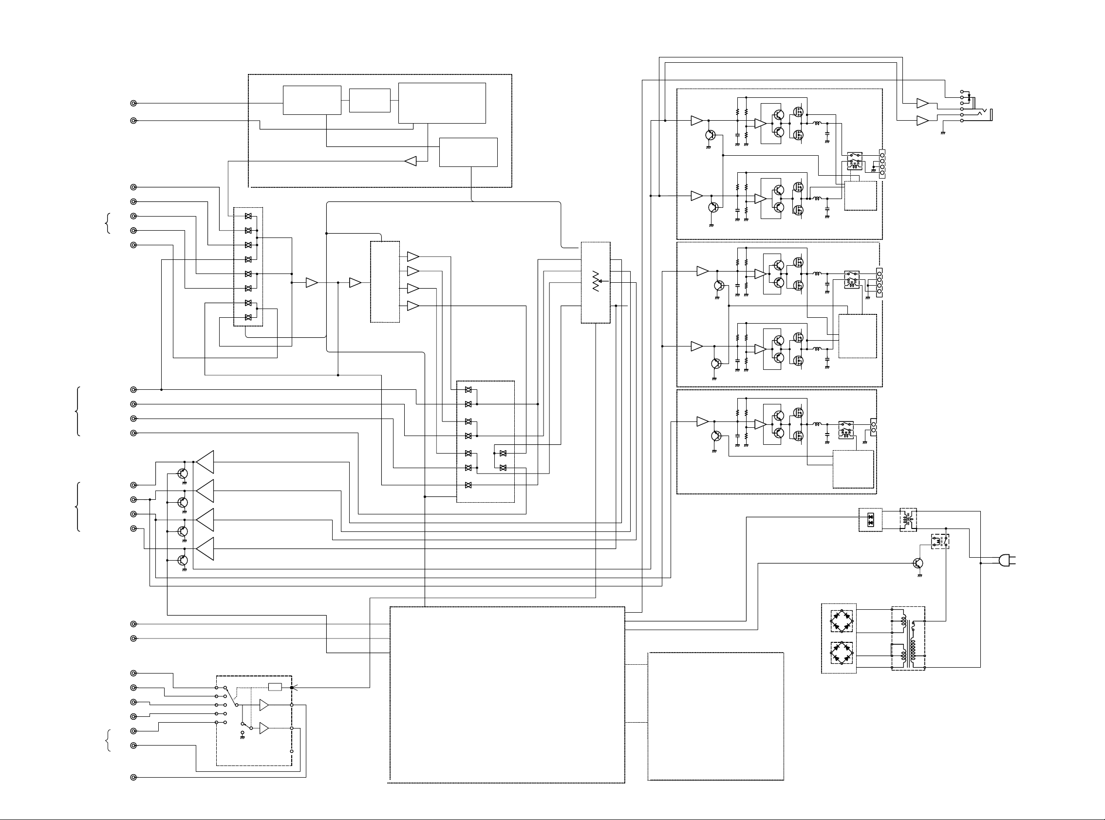
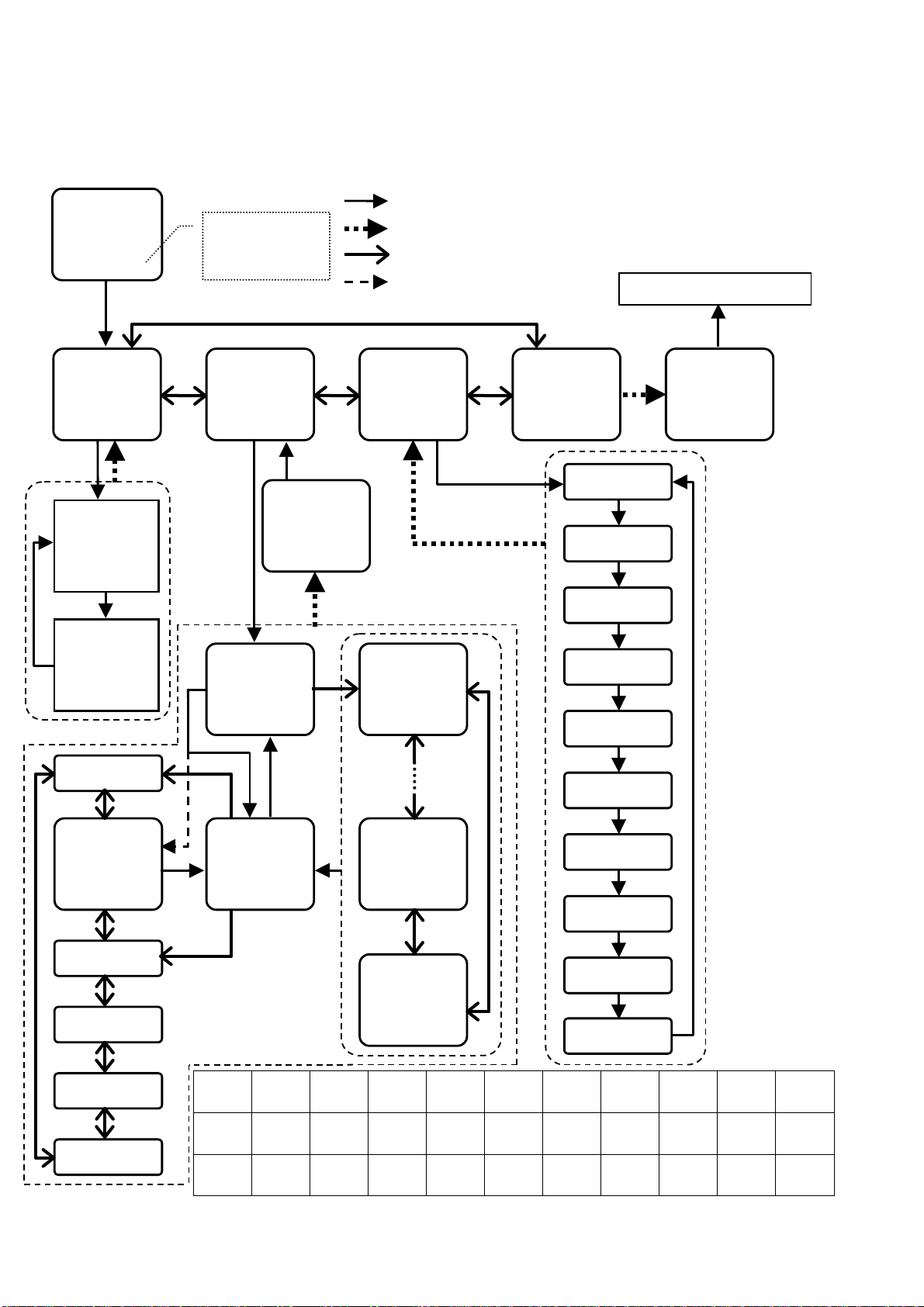
4. BLOCK DIAGRAM
TUNER_BLOCK
DIGITAL_AMP_UNIT
TUNER
AUDIO
INPUT
6CH
DIRECT
IN
FM
AM
TV
LD
IN
VCR
OUT
AUX
FRONT
REAR
L/R
L/R
CENTER
SUBWOOFER
SELECTOR
QS01
FM
A101
FRONT
END
QQ01
AMP
IF
MPX&FM/AM
Q201
P704
FRONT_L
-
PLL
Q301
CS_SURROUND
Q501
EL_VOLUME
FRONT_R
–
PROTECTER
HEADPHONE_AMP
FRONT
QW01
HEADPHONE
QG01
FRONT_L/R
SURR_L/R
CENTER
SUB.WOOFER
VIDEO
CONT1-4
P714
SURR.L
–
SURR.R
–
REAR
PROTECTER
SELECTOR
QS03
P724
CENT
–
CENTER
OUTPRE
BUS
VIDEO
FRONT
REAR
L/R
L/R
CENTER
SUBWOOFER
IN
OUT
AUX
DVD
TV
LD
IN
VCR
OUT
MUTE
QG02
QG03
QG04
VIDEO_SELECTOR
QL51
CONT
RC_IN
RC_OUT
MUTE
DATA_BUS
U-COM/KEY_INPUT
QU01
HEADPHONE
POWER
POWER_ON/OFF
DISPLAY
VU50
PROTECTER
BACKUP_SUPPLY
POWER_ON/OFF
POWER_SUPPLY
LCD/DRIVER
QU51
MONITOR
5
6
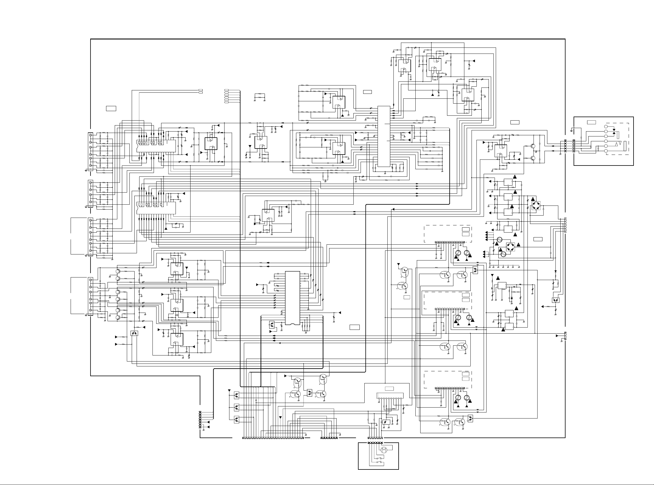
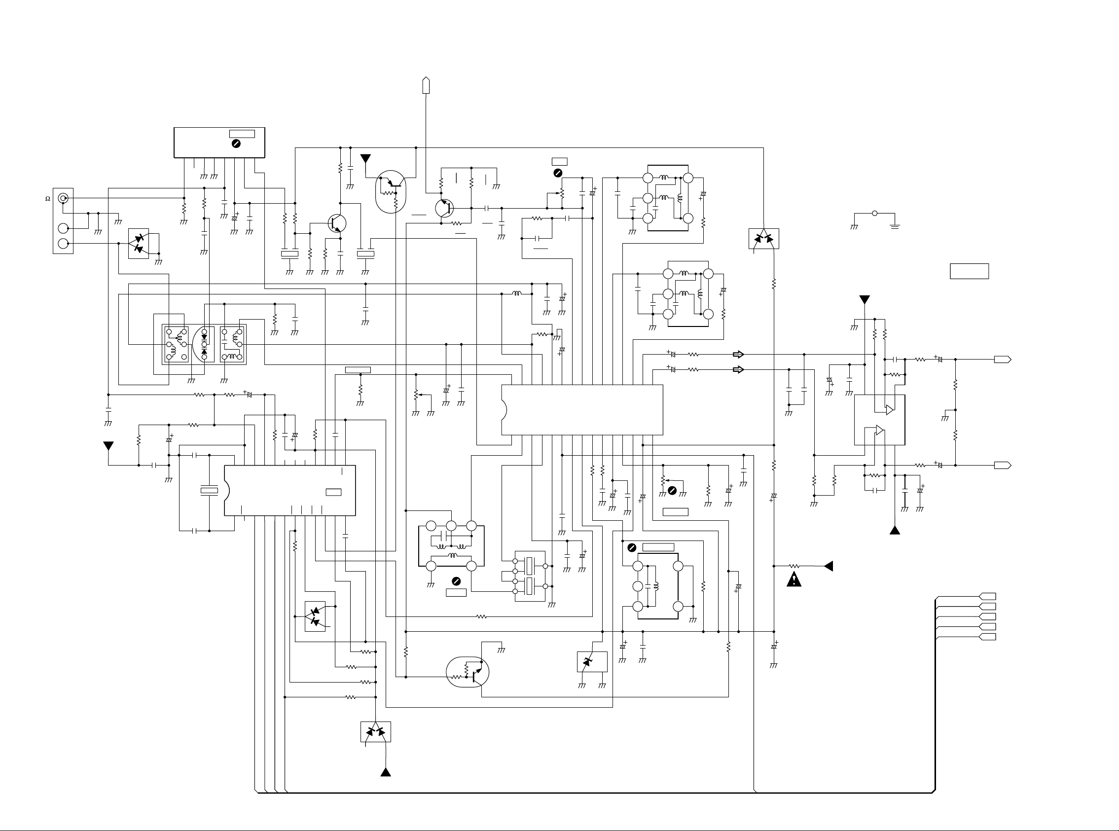
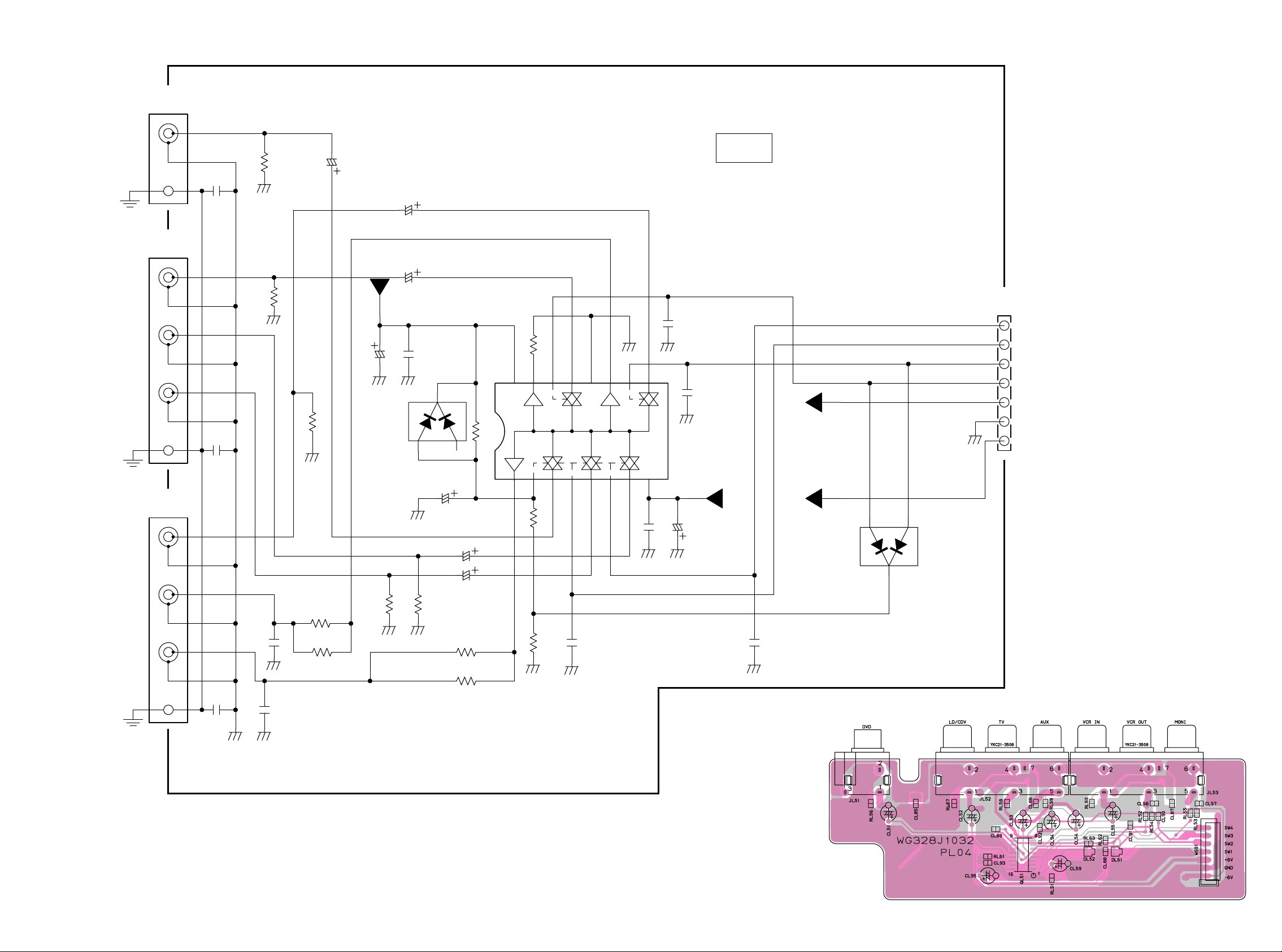
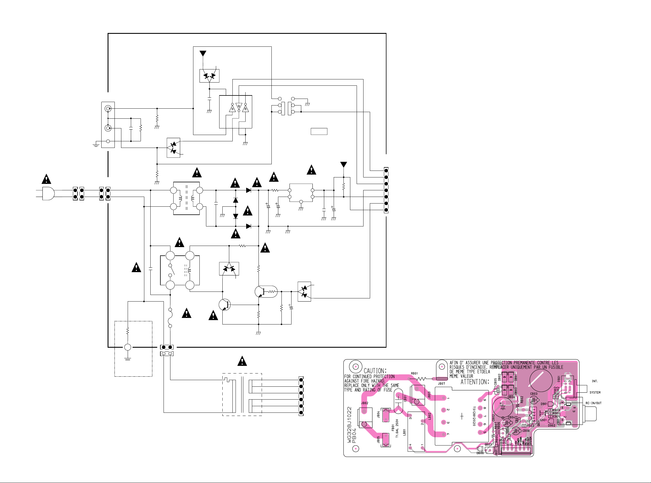
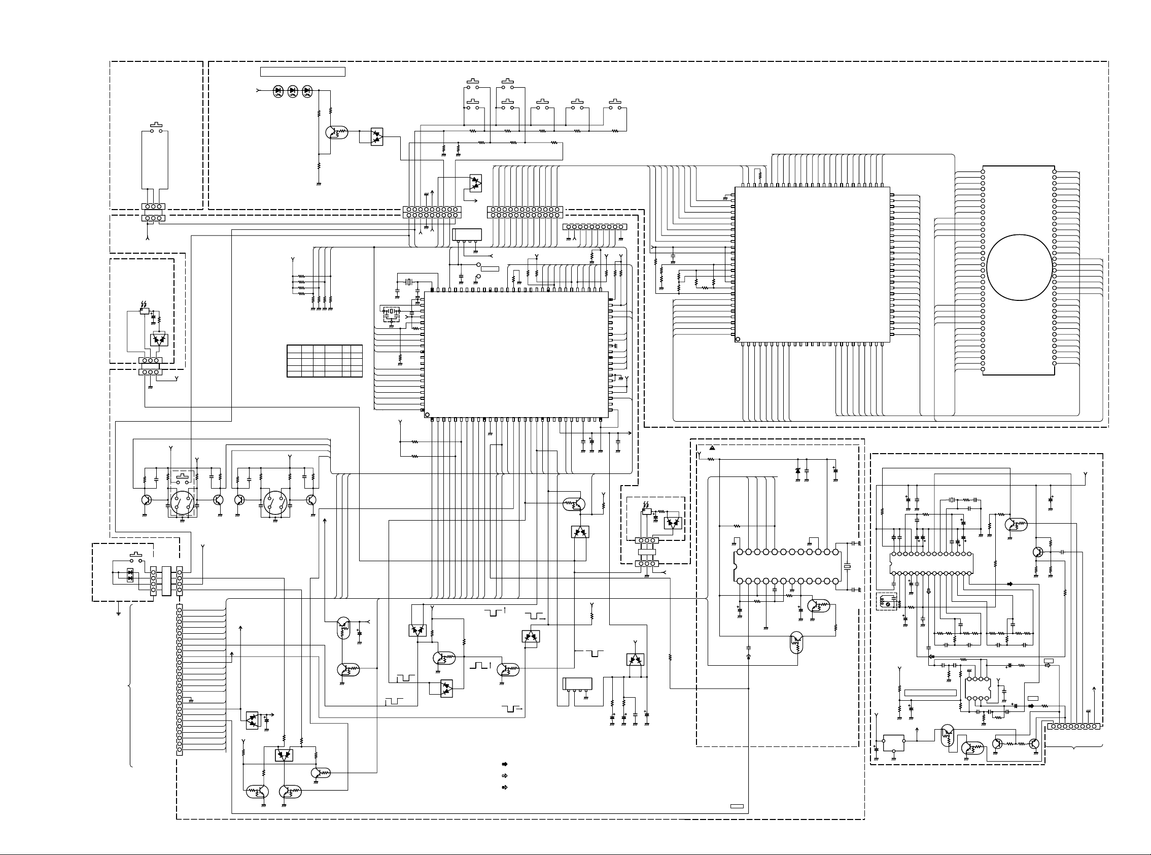
5. SCHEMATIC DIAGRAM AND PARTS LOCATION
RRJ
CS17
19
2021
SYSTEM
19
2021
2ch/5ch
SW/CENTER
12
CG44
0.1
NJM2068M
RG14
CG14
68p 50v
CG46
0.1
CG16
CG48
0.1
A-GND
NJM2068M
VDD
VEE13CE14DI15CL
RS36
100k
VDD
VEE13CE
-12V
RG13
10k
A-GND
QG02
10k
CG15
68p
50v
A-GND
68p
50v
CG17
68p
50v
A-GND
QG04
RS33
100k
16
17S18
VSS
RES
CS31
0.1
16
17S18
VSS
RES
CL
14DI15
CS30
100/16v
CS32
CG13 68p 50v
8
+V
1234
RG1710k
8
+V
1234
RG18
10k
RG2110k
8
+V
1234
RG22
10k
CG18
68p
50v
10/50v
CS25
10/50v
LC78213
0.1
765
+
765
+
RG20 2.2k
765
+
0.1
CS18
CS29
100/16v
A-GND
QS03
+
CG54
RG16 2.2k
+
CG56
+
CG58
RG24
3.3k
CS23
100/16v
A-GND
CS24
100/16v
CS26 0.1
A-GND
RG15 2.2k
A-GND
CG53
-V
RG19
2.2k
CG55
-V
CG45
RG23
2.2k
CG57
-V
CG47
0.1
A-GND
QG03
NJM2068M
0.1
A-GND
DVD
5.1CH INPUT
PREOUT
LD/VCD
SYSTEM AUX
VCR IN
VCR OUT
FRONT
SURROUND
CENTER
SUB-W
FRONT
SURROUND
CENTER
SUB-W
RS07
JS03
1k
YT02060460
7
L
9
8
R
4
L
6
TV
5
R
1
L
3
2
R
10
JS02
YT02040940
4
L
6
5
R
1
L
3
2
R
7
JS01
YT02060500
1
L
3
2
R
4
L
6
5
R
7
9
8
10
JG01
YT02060500
7
L
9
8
R
4
L
6
5
R
1
3
2
10
RS23
RS24
RS25
RS26
RS27
RS28
CS34 0
RS29
RS30
RS31
RS32
CS35 0
RS17
RS18
RS19
RS20
RS21
RS22
CS33 0
50v
220k
CS07
220p
RS08
50v
CS08
220p
1k
220k
RS09
1k
50v
CS09
220p
220k
RS10
50v
1k
CS10
220p
220k
RS11
1k
50v
220k
CS11
220p
RS12
50v
1k
CS12
220p
220k
RS99
0
RS13
50v
1k
CS13
220p
220k
RS14
50v
1k
220k
CS14
220p
RS15
1k
50v
220k
CS15
220p
RS16
50v
1k
220k
CS16
220p
RS98
0
RS01
50v
1k
CS01
220p
220k
RS02
50v
1k
220k
CS02
220p
RS03
1k
50v
CS03
220p
220k
RS04
50v
1k
CS04
220p
220k
RS05
1k
50v
220k
CS05
220p
RS06
50v
1k
CS06
220p
220k
RS97
0
A-GND
0
2SC4213
C
0
C
A-GND
QG06
E
2SC4213
50v
CG01
220p
0
50v
CG02
220p
0
E
QG07
2SC4213
50v
CG03
220p
C
0
C
50v
A-GND
CG04
220p
QG08
E
2SC4213
0
50v
CG05
220p
0
E
QG09
50v
CG06
220p
2SC4213
0
C
CG49
C
0
A-GND
RG65
0
E
0
QG10
A-GND
2SC4213
-12V
-12V
30
(LCH)(RCH)
QS01
LC78211
123 456789101112
1
RG01
RG07
1k
BEQG05
47k
RG50
0.7
4.7k
RG51
RG08
4.7k
B
47k
RG02
0.7
1k
RG52
RG03
4.7k
B
1k
RG09
0.7
47k
RG53
RG10
4.7k
B
47k
RG04
0.7
1k
RG55
RG05
4.7k
B
1k
RG11
0.7
47k
RG59
4.7k
B
RG54
0.7
RG06
1k
RG56
680k
DP02
1SS301/
DAN202U
RG57
680k
RG58
680k
22
2324
25
2627
28TV29
DVD
VCRIN
TUNER
LD/VCD
VCROUT
22
23CS24C25
26CS27L28
29CS30
L
REAR
FRONT
R
234R567SW891011
+12V
CG07
10/50v
A-GND
CG08
10/50v
CG09
10/50v
+12V
A-GND
CG10
10/50v
CG11
10/50v
A-GND
RG12
47k
CG12
10/50v
-12V
+12V
CG51
100/16v
AUX
-12V
A-GND
A-GND
CQ78
0.1
RQ70 10k
A-GND
A-GND
48
47
46
45
44
43
42
41
40
39
CQ60
38
0.1
37
A-GND
36
CQ61
0.1
35
AA-GND
34
33
32
31
30
29
28
27
26
25
RQ43
CQ33
1/50v
HEADPHONE_IN HIGH
HEADPHONE_OUT LOW
+12V
12.0
0
QP08
RN1303/
DTC124EU
4-V321
+
5678
RQ65
10
AA-GND
RQ66 10
4.7M
CQ31
1/50v
QP09
RN2303/
DTA124EU
A-GND
+
RQ44
RMD
RQ71
A-GND
10k
47k
RQ72
47k
RQ73
QQ05
A-GND
NJM2068M
RQ74
+V
47k
CQ77
0.1
A-GND
CQ41
0.47
RQ50
3.3k
RQ51
560
CQ51
CQ50
100p
100p
+6V
50v
50v
-6V
CQ48
D-GND
100p
50v
RQ47
100k
10k
FRONT_L
SURROUND_L
CENTER
FRONT_R
SURROUND_R
0
A-GND
RQ69
47k
A-GND
RQ03
RQ04
1.2k
RQ58
2.7k
QG01
M62446FP
CQ03
CQ07
RQ93
47k
LBASS1
LBASS2
LBASS3
4.7k
RQ06
RQ05
47k
1.8k
0.1
0.1
RQ11
RQ12
1.8k
47k
RQ09
RQ10
1.2k
4.7k
CQ63
10/50v
CQ64
10/50v
CQ13
0.1
RQ21
CQ14
560
1000p
560
RQ17
50v
RQ22
220
220
RQ18
CQ17
0.1
RQ25
RQ26
5.6k
2.2k
RQ30
RQ29
820
82
RQ35
RQ36
330
120
RQ39
RQ40
330
120
CQ43
1/50v
RQ56
RQ55
1.5k
560
RQ57
1.5k
CG33
0.33
21
20
CG32
19
0.015
18
LTRE
17
CG31
BYSL
8200p
16
25v
BYSR
15
LIN
14
GNDL
13
RIN
12
GNDR
11
CIN
10
GNDC
9
SLIN
8
SRIN
7
GNDS
6
A-GND
SWIN
5
AVDD
4
OUT1
3
OUT2
2
OUT3
1
OUT4
RG42
RG43 22k
RG44 22k
22k
D-GND
CS43
22/50v
+V
QS02
NJM4558M
CS44
22/50v
RDS_IN
+12V
CEO
DO
CLK
SD
DI
RG40
100
RG39 100
RG41
100
RS37
A-GND
RS38
RDS_IN
SD
CEO
DO
CLK
DI
47k
47k
CLK
DO
CEO
CLK
DO
CEO
R315
R316
AA-GND
T-GND
CQ89
RQ01
47p
10k
RQ89
10k
RQ99
10k
RQ91
0
5678
A-GND
-12V
CQ94
10/50v
RQ02
A-GND
A-GND
+V
+
+
4-V321
RQ92
0
CQ92
0.1
A-GNDA-GND
A-GND
CQ90
10k
47p
QQ04
NJM2068M
CQ83
100/16v
CQ84
0.1
+V
+12V
RQ95
10k
CQ45
RQ96
10/50v
47k
CQ87
47p
RG37
FRONT_L
100
RG38
FRONT_R
100
-6V
CG40
100/10v
A-GND
CE1 SW4
DO
CLK
DG01
1SS302
CQ91
0.1
NJM2068M
+
A-GND
+6V
A-GND
QQ08
RQ98
10k
RQ90
10k
4-V321
+
5678
RQ94
A-GND
CG36
8200p
25v
CG37 3.3/50v
CG38 3.3/50v
CG25 10/50v
CG26 10/50v
CG27 10/50v
CG28 10/50v
CG29
CG30 10/50v
10k
A-GND
A-GND
10/50v
AA-GND
D-GND
CQ93
10/50v
CQ85
100/16v
A-GND
CG34
0.33
CG35
0.015
100/10v
D-GND
SURROUND_R
SURROUND_L
CENTER
2CH/5CH_IN
+12V
CQ44
0.47
-12V
0.1
CQ86
A-GND
22
RBASS1
23
RBASS2
24
RBASS3
25
RTRE
26
CR2
27
CR1
28
CL2
29
CL1
30
AVSS
31
LOUT
32
ROUT
33
COUT
34
SLOUT
35
SROUT
36
SWOUT
37
AGND
38
DGND
39
LATCH
40
DATA
41
CLK
42
DVDD
CG41
TUNER_R
TUNER_R
TUNER_L
TUNER_L
TUNER BLOCK
(328J493B)
CS27
0.1
CS21
150p
+12V
RS35
100k
A-GND
-12V
RS34
100k
+12V
CG43
0.1
A-GND
A-GND
CG50
100/16v
A-GND
A-GND
50v
5678
CS19
+
100p 50v
+
-12V
4-V321
CS28
CS20
0.1
100p 50v
CS22
150p
A-GND
50v
RG25
1k
CG19
RG31
100p
100k
50v
RG32
A-GND
CG20
100k
100p
50v
RG26
1k
RG27
1k
CG21
RG33
100p
100k
50v
CG22
RG34
100p
A-GND
100k
50v
-12V
RG28
1k
RG29
1k
CG23
RG35
100p
100k
50v
CG24
RG36
100p
A-GND
100k
50v
-12V
RG30
1k
CQ05
0.01 50v
-12V
RQ08
RQ07
4.7k
100k
CQ04
CQ53
4700p
0.1
50v
CQ08
A-GND
4700p
50v
RQ14
RQ13
4.7k
100k
RQ19
39k
CQ15
RQ23
1000p
12k
50v
-12V
CQ59
RQ24
0.1
150k
CQ18
100p
RQ28
RQ27
220k
560k
CQ19
0.01
50v
RQ3182RQ32
820
CQ24
CQ26
0.1
0.1
A-GND
10/50v
CS37
10/50v
CS38
10/50v
CS36
10/50v
CS39
10/50v
CS40
CS41
10/50v
SW3
SW2
SW1
RG45 22k
A-GND
RQ34
CQ09
0.01
50v
CQ21 0.1
120
RQ20
1.2k
RQ38
120
A-GND
CQ22 0.1
RQ33
330
4-V321
+
+
5678
4-V321
+
+
5678
RQ37
330
CG39
100/10v
QQ01
NJM2068M
+V
CQ52
A-GND
+12V
QQ02
NJM2068M
+V
CQ54
0.1
A-GND
+12V
CQ23
1/50v
CQ25
1/50v
HEADPHONE_R
HEADPHONE_L
+6V
0.1
-6V
RVR
+6V
CQ16
10/50v
CQ20 10/50v
RQ97
100k
A-GND
AA-GND
RRK
QQ03
SSM2005
CQ06
10/50v
1
COUT
RFIN
2
LFOUT
RFOUT
CQ10
3
RFOUT
LFIN
10/50v
4
LSOUT
LFOUT
RQ15
CQ11
5
100
A-GND
RQ16
100
A-GND
RQ68
10
CQ57 0.1
RQ67
10
CQ27
10/50v
RQ54
RSOUT
LOUT
0.1
6
NIN
LOUTA
7
NOUT
LIN
8
LOAD
ROUT
9
CQ12
RST
ROUTA
0.1
10
DI
RIN
11
VCC
VEE
CQ56
12
AGND
AGND
0.1
13
GND
GND
A-GND
14
VEE
VCC
15
WR
(L+R)0
16
CLK
(L-R)0
17
(L-R)HI
F/RTF
18
(L-R)LO
LTF
19
RHBD
HTF
20
CHBD
FRD
21
HBD0
(L-R)D
22
RLBD
(L+R)D
23
LLBD
ABL0
24
LBT0
ABT
CQ30
CQ29
22/50v
1/50v
CQ28
0.1
CQ32
AA-GND
1/50v
RQ41
1k
RQ42
1k
RQ77
CQ80
10k
0.1
4-V321
10k
RQ75
+
+
5678
RQ76
RQ78
10k
10k
CQ68
47p
+12V
A-GND
RQ52
RQ53
33k
180
CQ42
1/50v
AA-GND
RQ63
100
CQ49
RQ62
100p
100
50v
CQ47
RQ61
100p
100
50v
RQ60
100
RQ48
RQ49
270k
3.9k
CQ39
0.1
CQ37
1/50v
RQ46
RQ45
3.9k
270k
CQ34
1/50v
WG328J2010
P704
FRONT_BLOCK
MAIN AMP
JP01
YJ06008820
12JQ
123456789101112
A-GND
CP04
100p
A-GND
RP04
WG328J2020
P714
SURROUND_BLOCK
MAIN AMP
JP02
YJ06008820
123456789101112
12JQ
A-GND
CP06
100p
A-GND
+V
CQ70
10/50v
100/16v
CQ35
0.1
AA-GND
A-GND
R_IN
A-GND
0
QP01
RN1303/
DTC124EU
A-GND
R_IN
CP05
100p
0
QP02
RN1303/
DTC124EU
CQ67
47p
QQ06
NJM2068M
A-GND
CQ79
0.1
CQ75
CS_RESET
(2125)
CQ38
1/50v
CQ36
0.22
(2125)
L_IN
CP03
100p
11.0
L_IN
A-GND
11.0
CQ69
10/50v
A-GND
DO
CE2
CLK
CQ40
0.22
RELAY+B
A-GND
RELAY+B
OSC SHIFT OSC SHIFT
A-GND
RQ79
47k
RQ80
47k
A-GND
RQ81
47k
RQ82
47k
10k
RQ84
PR-GND
+12V
RELAY
-12V
PR-GND
QP10
012.0
RN1303/
DTC124EU
-12V
+12V
PR-GND
RELAY
PR-GND
QP11
0
RQ83
CQ82
10k
A-GND
CQ72
+BA
PA-GND
T3.15A
+BB
PB-GND
T3.15A
0.1
47p
PA-GND
FP01
250V
PB-GND
FP03
250V
A-GND
4-V321
+
+
5678
RQ86
10k
RMA
RMP
-BA
-BA+BA
A-GND
RMB
RMP
-BB
-BB+BB
A-GND
CQ76
100/16v
CQ71
47p
RQ85
+V
FP02
T3.15A
250V
T3.15A
LP02 100UH
-12V
10k
QQ07
NJM2068M
CQ81
0.1
CQ74
10/50v
DP04
1SS301/
DAN202U
FP04
250V
LP01
100UH
NLC453232
NLC453232
A-GND
100UH
CQ73
10/50v
RQ88
47k
-12V
-BC
-BB
-BA
LP03
LP04
100UH
10/50v
RQ87
47k
A-GND
CW10
+BD
+BC
+BB
+BA
A-GND
NJM4556AM
RW11
2.2k
+6V
470/10v
+12V
A-GND
10/50v
-12V
AA-GNDV-GND
-6V
C807
6800/50v
GND
R831
2.2
1/6w
PR-GND
QW01
A-GND
C818
AA-GNDV-GND
C822
470/10v
PA-GND
L831 10UH
C830
DD-GND
CW04
RW06
47p
2.2k
RW04
CW14
A-GND
39k
4567
CW12
0.1
+
CW11
0.1
+
3218
CW13
RW03
CW05
10/50v
RW05
39k
2.2k
CW03
47p
Q803
NJM7806FA
1
+6V
C817
0.01
50v
2
0
Q802
NJM7812FA
1
12.0v 17.4v
+12V
C820
0.01
C819
2
10/50v
50v
0
C821
3
0.01
50v
1
-12V
-12.1v
R806
4.7 1/6w
C823
0
0.01
3
50v
C824
1
-6V
-5.9v
Q804
NJM7906FA
F803
250VT5.0A
3
C808
1
6800/50v
F804
J801
PC-GND
PR-GND
PB-GND
+BD
Q830
LM2575HVT
37.2v
12.2v
FB1VIN
4
12.0v
3
OUTPUT
2
0
GND
5
CDRH5D28
ON/OFF
0
R832
47
C837
220/63v
1000p
DD-GND
DD-GND
Q805
NJM7812FA
1
12.1v
+12V
C826
0.01
C827
2
10/50v
3
C828
0.01
C829
10/50v
1
-12V
-12.1v
Q806
NJM7912FA
RHP
CW06
10/50v
RW08
560
CW09
10/50v
A-GND
RW07
560
11.7v6.1v
3
R805
4.7
1/6w
3
C832
0.01
50v
C833
0.01
50v
2
-18.4v
Q801
NJM7912FA
C834
0.01
50v
2
-11.7v
D801
S5VB
4
2
250VT5.0A
D-GND
DD-GND
L832
10UH
CDRH5D28
L830
220UH
R833
1k
C838
470p
D830
RB160L-60
DD-GND DD-GND
-17.3v
3
C805
0.01
50v
0
C804
0.01
50v
2
-18.4v
JT01
RHP
WT01
N_ONLY
EARTH
CT03
JT02
JW01
YP0601045X
CW08
100p
QW02
-0.1
50v
2SC4213
0
RW10
4.7k
0
QW03
A-GND
2SC4213
CW07
100p
0
50v
RW09
4.7k
+12V
-0.1
C831
0.01
50v
C815
2200/25v
D804
S2VB
1
3
2
C816
4
2200/25v
GND
EH-5P
5
4
3
2
R
1
L
A-GND
C802
0.01
500v
YP06003690
6
5
4
3
2
1
0.1
YP0601045X
EH-5P
5
N_ONLY
4
CT11
1000p
3
50v
2
1
(WT02)
J802
VH-6P
TO L001
(TRANSF)
YJ01004710
6
5
4
3
2
CT12
1000p
50v
1
HEADPHONE PCB
WG327J1040
PT04
RPS
C801
0.01
500v
DP03
SFPL-52V
RP01
0.47/50v
DP10
1SS301/
DAN202U
RP03
CP01
1k
220/25v
1k
47k
RP02
GND
CP08
GND
J831
YP0600383X
EH-3P
1
2
+BD
3
DD-GND
C836
470/25v
DD-GND
C835
470/25v
+VM
GND
CQ66
CQ65
10/50v
47p
FROM WG01
(PL04)
(VIDEO BLOCK)
WG328J2030
P724
CENTER_BLOCK
MAIN AMP
R_IN
JP03
YJ06008820
123456789101112
12JQ
A-GND
CP02
100p
A-GND
RP05
0
QP03
RN1303/
DTC124EU
A-GND
L_IN
11.0
OSC SHIFT
V-GND
YP06010460
SW4
SW3
SW2
SW1
+6V
-6V
8.0
0
A-GND
25242322212019181716151413112111098765432
D-GND
P.DOWN
D.CLOSE_SW.
SYSTEM_IN/OUT
DP01
1SS301/
DAN202U
7.4
RN1303/
DTC124EU
YP06010460
8.0
QP04
EH-7P
8.0
QP05
RN2303/
DTA124EU
0
0
A-GND
1234567
JS05
+6VD
RC_IN
D-GND
POWER
P_DOWN
TO JB05
(PB01)
(POWER/REMOTE PCB)
RC_OUT
SYSTEM
D-GND
OSC_SHIFT
YP06006660
UP CONNECTOR
JM01
(RMO)
CM02
0.01
021C
QM01
LB1641
12345678910
DD-GND
5.7v
CM01
0.01
CM05
CM03
0.1
0.01
DM02
DD-GND
D-GND
654321
123456
CLOSE
OPEN
RMO
DOOR_MOTOR
0.9v
1.5v
220
RM01
008C
DOOR MOTOR
LIMIT SW1
LIMIT SW2
0v
DD-GND
DD-GND
016C
016C
0v
RM02
2.7k
12v
12v
RM04
390
DD-GND
RM03
-5.3v
0.7v
4.7 1/4w
CM04
220/16v
DD-GND
CM06
DOOR_OPEN/CLOSE
CE1
CLK
CE1
CLK
+6VD
D-GND
WV01
TO JV04
(PV04)
(FRONT PCB)
DO
+VM
CLK
8.0
QP07
RN2303/
DTA124EU
DO
CEO
+12V
DO
CEO
2/5_OUT
D.OPEN_SW.
0
QP06
RN1303/
DTC124EU
+12V
MUTE
RC_IN
POWER
RC_OUT
D.MOTOR_REV.
D.MOTOR_FWD.
CE2
CS_RESET
CS_RESET
POW-MUTE
2CH/5CH_IN
CE2(CS_WRITE/LOAD)
RDS_IN
DI
SD
0.1
CP09
SD
DI(PLL_DO)
OSC_SHIFT/FM_OUT(RDS)
+6V
DP09
1SS301/
JG51
EH-7P
SW4
7
SW3
6
SW2
5
SW1
4
3
+6V
2
1
-6V
V-GND
DAN202U
DP07
1SS301/
DAN202U
DP08
1SS301/
DAN202U
YJ07011550
9604S-25C
JS04
7
A-GND
RMC
RMP
RELAY+B
RELAY
+12V
PR-GND
-12V
+BC
PC-GND
-BC
PC-GND
FP06
T3.15A
PR-GND
0
250V
FP05
T3.15A
250V
LP05
100UH
-BC
+BC
NLC453232
LP06
100UH
NLC453232
DP06
1SS301/
DAN202U
QP12
A-GND
WG328J1012
PV04
8
RDS_IN
FM75
GND
AM
J101
YT03030020
1
2
3
4
TA-GND
T-GND
+12V
T-GND
C507
0.01
DA06
1SS302
1k
R506
C509
0.01u
50v
ANT NC GNDGNDVT+BIFOUT
T-GND
10k
R101
1/2W
U-only
T-GND
T-GND
TA-GND
43
L1
13
1221
T-GND
R504
4.7k
C508
100/16v
C502
47p
T-GND
X501
7.2MHz
C501
47p
RA01
CA01
R510
4.7k
10k
0.01
5
VCD
11
A101
AV01202270
43218765
T-GND
C218
0.01
T-GND
67
14
10
T-GND
R502
ST DISTFM FRONT-END
C216
100/16v
T-GND T-GND
LA01
7RBW-3702
8
L2
9
C505
2.2k
2.2/50v
24
23
22
VSS
XOUT
B051XIN
2
OSC
OUT
C202
21
AOUT2
CE0
4DI3
0
0.01
R201
F201
C:SFF10.7MA8-A
N:SFE10.7MS3-A
RA02
T-GND T-GND
R505 1k
20
PD219PD1
AIN2
LC72130
T-GND
100k
C504
0.01
18
Q501
R203
T-GND
CA03
C503
17
AIN1
R511 8.2k
1SS301/
DAN202U
Q202
2SC2714
2.4
1.5k
(0)
390
R202
T-GND T-GND
9p
100/10v
16
15
VDD
AOUT1
D504
R507 68k
14
FMIN
PLL
11
R205
R204
330
470
C511
13
AMIN
I0110B049B038B027B016DO5CLK
12
T-GND
10.6
(0)
1.7
(0)
C201
FM MUTE
0.01
I02
IFIN
R515
10k
R513
10k
C223
0.01
T-GND
T-GND
C510
100p
+12V
0.01
T-GND
R212
4.7k
R508
47k
R509
22k
DTA114EU/
RN2302
(12.0)
F202
SFE10.7MS3-A
C237
0.01
Q203
0
STRQ/MUTE
RDS_IN
11.8
(0)
Q206
N:2SC4116
C:
R299
T-GND T-GND
3
4
T-GND
R214
47k
0
(2.0)
R219
N:10k
R221
N:100k
C:
C219
10/50v
T-GND
T-GND
21
AM IF
DTC144EU/
RN1304
C:
Q204
6
C203
R222
C221
N:0.01
C:
0.047
LA06
K7-H5
R216
27k
C:
N:100k
T-GND
(0)
SEP
C209
C217
N:0.015
C:0.027
C205
1/50v
T-GND
T-GND
C214
25
AFC
C235
T-GND
C215
T-GND
47/16v
24
AGC
0.047
C220
2200p
23
AMO
Q201
LA1837
0.01
C206
10/50v
T-GND
D202
9.1V
T-GND
1/50v
22
FMO
R220 100
T-GND
21
MPXI
R213
C210
T-GND
20
MPXO
47
0.01
T-GND
R211
N:22k
C:10k
R215
N:68k
C222
1500p
T-GND
T-GND
7.7
C:27k
C227
N:
C:2200p
LA05
C204
39mH
30
FMSD
FMIFI2AMMIXO3FMIFB4AMIFI5GND6AFIFO7AFIFO8VCC9FM10AMCF11FMS12AMS13IFBO14LPF15LPF
1
6
4
3
1
SFZ450JL3
0.047
T-GND
R206
6.8k
26
27
28
29
RFI
OSC
REG
2
5
FA01
T-GND
C301
N:0.033
19
MPXO
T-GND
T-GND
C:0.047
C311
AMPIO
C234
4.7/50v
3
2
1
2700p
T-GND
C302
C:0.047
N:0.033
C312
2700p
T-GND
16
17
18
AMPIO
AMPIO
C236
0.01
C213
0.47/50v
MONO DIST
3
2
L201
M292BEAS-5968Z
C207
C208
100/16v
T-GND
L301
19/38kHz LPF
L302
19/38kHz LPF
3
2
1
C309
10/50v
C310
10/50v
AMPIO
RA11
10k
T-GND
T-GND
AM STOP
0.047
R303
4
61
6
4
1k
R304
1k
T-GND
T-GND
RA12
C303
R301
6
4
R208
10/50v
2.7k
CA18
T-GND
2.7k
C304
10/50v
2.7k
R302
TUNER_L
TUNER_R
C226
T-GND
4.7/50v
R209
0.01
4.7k
C211
2.2/50v
D201
1SS301
/DAN202U
3.3k
R210
T-GND
4.7k
R218
C308
2200p
T-GND
C212
1/50v
R207
100 1/4w
C233
100/16v
C307
2200p
R308
47k
T-GND
C320
T-GND
100/16v
10k
R312
+12V
T-GND
C316
T-GND
0.01
-12V
-V
J301
R307 47k
+
R306
10k
C318
680p
R311 10k
EARTHT-GND
C317
680p
R305
10k
1234
+
+V
8765
+12V
R309
220
Q301
NJM4558M
R310
220
C315
0.01
T-GND T-GND
C305
4.7/50v
C306
4.7/50v
C319
100/16v
T-GND
CEO
DI
CLK
DO
SD
RTU
TUNER_L
R313
47k
R314
47k
TUNER_R
TUNER_L
TUNER_R
CEO
DI
CLK
DO
SD
D505
1SS301/
DAN202U
CEODOCLKSDDI
+6V
9 10
JL51
YT02010560
DVD
EARTH
LD
TV
AUX
EARTH
VCR
JL52
YT02030590
JL53
YT02030590
1
2
3
4
5
6
7
1
2
1
2
3
CL85
0.1
CL86
0.1
82
RL56
V-GND
RL57
V-GND
82
CL51
RL60
V-GND
10/50v
82
+6V
CL95
100/10v
V-GND
DL52
CL55
10/50v
CL52
10/50v
V-GND
V-GND
0.1
CL93
CL59
100/10v
CL54 10/50v
16
RL51
150
RL61
15 14 13 12
+V
RL63
6.8k
V-GND
11 10 9
GND
7654321
V-GND
8
V-GND
NJM2296M
-V
0.1
CL92
V-GND
CL88
V-GND
QL51
CL94
CL89
100/10v
RVC
-6V
WG328J1032
PL04
+6V
-6V
V-GND
DL51
1SS301
/DAN202U
WG01
YB00111112
7
6
5
4
3
2
1
SW4
SW3
SW2
SW1
(MAIN PCB)
+6V
V-GND
-6V
TO JG51
(PV04)
VCR
OUT
MONI
OUT
EARTH
3
4
5
6
7
CL87
0.1
V-GND V-GND
47p
CL56
V-GND
CL57
47p
RL52
150
RL54
150
82
82
RL58
RL59
V-GND V-GND
CL53
10/50v
RL53
150
RL55
150
V-GND
RL62
6.8k
V-GND
CL90
CL91
V-GND
QL51
PL04
11 12
AC
230V
50/60Hz
REMOTE
CONTROL
W001
J001
YP04000580
1
2
AC
INLET
1
2
W002
YT02020890
IN
OUT
1
2
J901
JB03
YP04000760
1
2
+6VD
WG328J1022
PB04
D902
1SS301/DAN202U
765
8
CB05
0.01
+V
1234
DB03
SFPL-52V
GND
DB04
SFPL-52V
GND
D-GND
DB01
SFPL-52V
DB02
SFPL-52V
1 1/6w
CB02
1000/25v
RB02
D-GND
S901
SS02021470
SSSS92
12.8V
4.8V
CB03
4.7/50v
QB01
L76MR06
+6V
3
D-GND
D-GND
RPB
5.9V
51
42
5.8V
0.1
CB07
D-GND D-GND
+6VD
10k
RB03
CB06
10/50v
JB01
YP06010460
EH-7P
7
SYSTEM
6
RC-OUT
5
RC-IN
4
D-GND
3
P-DOWN
2
POWER
1
+6VD
TO JS05
(PV04)
(MAIN PCB)
YA01075020
(JS05 TO JB01)
C901
1
3
2
4
0.1
C902
R902
47
D-GND
R901
47k
D901
1SS301/DAN202U
R903
47k
D-GND
1
2
3
LB02
TS12812020
4
19
0.01
D-GND
Q901
TC7W14FU
5
JB07
EARTH
U-ONLY
RB01
2.2M 1/2W
CB01
0.01
21
21
2
3
JB04
2
FB01
1
JB05
YP04000760
250VT1.6A
JB02
VH-B3P
LB01
G5PA-1
TV-5
1
4
QB03
2SC2705
DB06
1SS301/DAN202U
C
B
E
1
2
RB07
22
1/4w
TS17207010
L001
4.7k
RB06
RB05
100k
D-GND
GND
QB02
DTC114TS
BLU
3
WHT
4
BLU
5
ORG
6
BLK
7
ORG
8
RB04
100k
D-GND
1SS301/DAN202U
CB04
1
2
3
4
5
6
DB05
1/50v
PB04
QB03 QB02
Q901
QB01
13
14
RPM-670CBR
PU94
(RLD)
DU91
WH31
WV01
TO JV04
(PV04)
PU84
(RLD)
QU81
RU31
QU31
2SC4116
SU91
POWER
CE2(CS WRITE/LOAD)
PU74
(RLD)
DOOR
SU71
*
JU71
123
WU71
123
JU06
VCC_B
CU81
100/6.3V
RU81
100
DU81
ISS300
JU81
123
WU81
123
JU07
RU32
CU31
15K
220P
47K
CU32
220P
44
RED
3
2
GRN
1
JU91
D.CLOSE SW.
P.DOWN
SYSTEM IN/OUT
D.MOTOR REV.
D.MOTOR FWD.
POWER
RC OUT
MUTE
RC IN
+12V
2/5_OUT
D.OPEN SW.
GND
FM-OUT/OSC_SHIFT
DI(PLL-DO)
CS RESET
POW_MUTE
2CH/5CH_IN
VCC_B
WU02
DO
CE0
CE1
+6V
LCD BACK LIGHT LED
TUNER MODE TUNER
**
SU56 SU57
DU51 DU52 DU53
** *
SU53 SU54 SU55
RU54RU53RU52
3.3K2.2K1.5K
RU60
3.3K
LCD_E
LCD_A0
LCD_D4
LCD_D2
LCD_D1
LCD_D0
LCD_D3
LCD_D4
LCD_D3
IR-IN
10K
RU70
IR-IN
QU01
MB90583B
16 BIT CPU
FUJITSU
TIM-LED
CE2(CS WRITE/LOAD)
CE2
POW_ON
QU04
RN1303
LCD_D2
POW-ON
LCD_D1
10K
RU42
IR-KIL
TTXD
LCD_D0
LCD_A0
LCD_E
VCC_B
10K
CE3
RU24
CE3
RC OUT/TRXD
TCK
TTXD
TCK
DU04
ISS300
LCD_RW
LCD_RW
AUD_MUT
MUTE
RC IN
:AUDIO L,R
:FM L,R
:AM L,R
LCD_RST
12
12
JU04
LCD_RST
VCC_B
JOG_A
JOG_B
2/5CH_IN
2CH/5CH_IN
VCC
24
CS_RESET
TRXD
HOLD
QU19
RN1303
RU55
6.8K
TMODE
RU39
47K
D-CLS
D-OPEN
D-OPEN
D-CLOSE
2/5CH_OUT
CS RESET
POW_MUTE
25 26 27 28 29
CU15
0.1
POW_MUTE
QU20
S-80843ALNP
4.3V RESET
RU56
10K
LCD DISPLAY
JU05
FLUSH WRITER
TAUX3
RST
TCK
TRXD
TTXD
TAUX
VCC_A
VCC_B
TAUX3
10K
10K
10K
HOLD
D-REV
D-FWD
D-FWD
MODEL
JAPAN
KEY_1
KEY_0
C
CU03
100/6.3V
DU08
ISS300
5253545556575859606162636465666768697071727374777879
D-REV
RDS
AVSS
AVRL
AVRH
AVCC
IR-IN
RU40
51
50
49
TAUX3
48
HST(HOLD)
47
46
45
44
43
42
41
40
LW
39
38
37
36
35
34
33
32
31
30
VCC_B
10K
RU25
TMODE
MODEL
LW
KEY_1
KEY_0
2/5CH_OUT
VOL_B
VOL_A
RU29
JPN
RDS
VCC_A
VCC_A
CU04
0.01
RU28
PU44
QU41
IR SENSOR
WU08
11223
JU08
VCC_B
RU09
10K
+6V
CU05
0.22F
DU02
ISS300
RU02
RU01
0
0
CU14
5.5V
0.01
CU02
0.22F 5.5V
IR-OUT
PU04 U-COM PCB
(RLC)
PU54
(RLD)
LCD_D6
LCD_D7
LCD_RST
LCD_+B
RU75
RU98
10K
RU67
4.7K
CU41
RU41
47/6.3V
100
DU41
ISS300
3
JU41
CU13
100/6.3V
LCD_D5
0
RU63
10K
+6V
LCD_D4
(RLD)
RU43
10K
COM_0
COM_1
COM_2
COM_3
COM_4
COM_5
COM_6
LCD_D3
CU51
0.01
RU62
LCD_D2
10K
RU64
10K
LCD_D1
LCD_D0
RU66
+12V
0
470 1/4W
RDS_KIL
R356
RU65
10K
COM6
SEG_0
SEG_1
SEG_2
SEG_3
SEG_4
SEG_5
SEG_6
SEG_7
SEG_8
SEG_9
SEG_10
SEG_11
SEG_12
SEG_13
SEG_14
SEG_15
SEG_16
SEG_17
SEG_18
SEG14
SEG_50
CH
C357
15p
CH470k
55606570
SEG50
SEG_49
X351
4.322MHz
SEG15
SEG49
SEG_48
SEG_19
SEG19
51
SEG20
SEG_20
50
SEG_21
SEG18
SEG17
SEG16
SEG21
SEG_22
SEG22
SEG_23
SEG23
SEG_24
SEG24
SEG_25
45
SEG48
SEG25
SEG30
SEG35
SEG40
SEG47
SEG26
SEG27
SEG28
SEG29
SEG31
SEG32
SEG33
SEG34
SEG36
SEG37
SEG38
SEG39
SEG41
SEG42
SEG43
SEG46
25
SEG_26
SEG_27
SEG_28
SEG_29
SEG_30
40
SEG_31
SEG_32
SEG_33
SEG_34
SEG_35
35
SEG_36
SEG_37
SEG_38
SEG_39
SEG_40
30
SEG_41
SEG_42
SEG_43
SEG_44
26
SEG44
SEG45
SEG_47
SEG_46
SEG_45
CA78
100/10V
RA74
1K
CA72
1000P
CA73
1000P
28 27 26 25 24 23 22 21 20 19 18 17 16 15
2.9
8.0
7.3
123456789
2.9
2.9
7.2
CA51
1000P
RA99
RA77
LA51
100K
10K
450KHZ
(AM SEP.ADJ)
CA53
10/50V
P154
(RTA)
+9V
8.0
10/50V
CA54
47/16V
CA70
1.3
3.6
0.9
CA81
0.1
RA62
2.2K
1000P
CA55
CA56
CA79
CA71
0.01
1000P
0.2
0.01U
1M
LCD_RD
LCD_RW
LCD_A0
RU68
RW
E
75
VSS
76
80
90
COM5
100
D0
D1
D2
D4
D5
D6
D7
85
RST
FR
V5
V3
M/S
V4
V1
COM0
95
COM2
COM3
COM4
D3
VDD
V2
COM1
1
COM8
OSC2
COM9
A0
OSC1
COM10
5
SEG4
SEG3
SEG2
SEG1
SEG0
COM11
COM12
COM13
COM14
COM15
10 15 20
SEG6
SEG5
QU51
NJU6450A
LCD DRIVER
SEG60
SEG59
SEG7
JRC
SEG58
SEG57
SEG8
SEG56
SEG9
SEG55
SEG10
SEG54
SEG11
SEG53
SEG12
SEG52
SEG13
SEG51
COM7
SEG_53
SEG_52
15
0
0
10
C358
100/6.3V
14
0
0.7
00
11
12 13
R354
10k
SEG_51
C356
15p
R357
10k
C352
10/16V
COM_7
COM_8
N ONLY
CE3
24
23
5.1
3.7
1.4
1.4
123
C353
330p
COM_9
COM_10
COM_11
TUN_DI
TUN_CLK
21
22
2.1
2.1
0.4
1.4
45678
R352
100k
COM_12
RDS_DO
C354
560p
COM_13
20
1.1
2.3
COM_14
COM_15
D351 C351
5.1V 0.01
LC72722
17
18
19
2.5
2.5
2.5
2.6
1.2
2.8
R353
C355
10/16V
Q351
16
0
1.5
9
Q352
RN2303
Q353
RN1303
RDS DECODER
F ONLY
+12V
CA77
10/50V
RA87
220K
RA88
220K
QA59
NJM7809F
AM STEREO BLOCK
CA88
10/50V
+9V
(RTR)
ONLY N-VERSION
COM_7
COM_8
COM_9
COM_10
COM_11
COM_12
COM_13
COM_14
CA69
22/16V
5.200.4
1.8
1.2
L OUT
50V
RA53
47K
CA83 CA85
0.1 0.1
RA81
27K
(RTA)
QA58
RN2303
SEG_22
1
SEG_21
2
3
DISPLAY
4
5
6
7
8
9
10
11
12
13
14
M12STEREO
15
16
17
TUNER
18
19
FM102.75MHz
20
21
22
23
24
25
26
27
28
29
30
31
32
33
34
35
RA75
100K
1.7
180K
RA73
RA51
47K
MC13022A
R OUT
RA70
6.8K
RA54
47K
CA58
330P
CA75
+9V
10/50V
1234
CA87
0.01
0.1
CA84
RA82 RA84
27K 12K
RA89
10K 10K
QA55
2SD2144
S/U/V
LCD
VU51
CA62
680P
RA58
27K
CA76
10/50V
CA82
0.1
QA53
RN1303
QA54
2SC4116
RA56
47K
RA72
6.8K
CA60
RA59
47K
RA90
QA56
2SD2144
S/U/V
330P
RCH
SEG_20
SEG_19
SEG_18
SEG_17
SEG_16
SEG_15
SEG_6
SEG_5
SEG_4
SEG_3
SEG_2
SEG_1
SEG_0
SEG_7
SEG_8
SEG_9
SEG_10
SEG_11
SEG_12
SEG_13
SEG_14
SEG_23
SEG_24
SEG_25
SEG_26
RA61XA51
CA66
2.7K3.6MHZ
0.01
CA67
47P (CH)
CA68
1/50V
10/50V
0.22
CA65
CA64
CA63
0.47/50V
0.1
2.9
2.9
2.9
2.9
6.4
1.2
RA69
6.8K
1.2
RA86
RA85
1M
1M
1.2
RA57
27K
1.2
RA83
CA61
680P
RA55
CA59CA57
1.2
47K
QA51
1413121110
1.8
RA71
6.8K
330P330P
12K
QA52
4558MD
5678
CA86
0.1
QA57
RN1303
RA78
4.7K
RA60
47K
MONO:5V
STEREO:0V
CA52
1000P
LCH
SEG_27
36
SEG_28
37
SEG_29
38
SEG_30
39
SEG_35
40
SEG_36
41
SEG_37
42
SEG_38
43
SEG_47
44
SEG_48
45
SEG_49
46
SEG_50
47
SEG_51
48
SEG_52
49
SEG_53
50
51
52
53
54
55
56
57
SEG_46
58
SEG_45
59
SEG_44
60
SEG_43
61
SEG_42
62
SEG_41
63
SEG_40
64
SEG_39
65
SEG_34
66
SEG_33
67
SEG_32
68
SEG_31
69
CA80
10/50V
RA63
47K
RA64
100K
RA65
2.7K
1234567
ST
L-CH
R-CH
MONO
MUTE
WA01
(PV04)TO JA01
+9V
AMIF
COM_0
COM_1
COM_2
COM_3
COM_4
COM_5
COM_6
+12V
GND
JA51
8
VCC
FM-IN
+6V
ENTER
JOG/
SU31
+12V
PU54 LCD/TACT SW PCB
RU11
DUMMY
RU12
10K
RU36
15K
SU32
VOLUME
RU38
15K
VCC_B
VCC_B
RU34
15K
CU33
220P
QU32
2SC4116
CU34
220P
VCC_B
RU33
47K
RU35
47K
CU35
220P
QU33
2SC4116
CU36 CU38
220P 220P
RU71
470
RU74
0
VCC_B
RDS
JPN
OLD/NEW
RU10
DUMMY
RU13
DUMMY
RU17
0
RU16
DUMMY
RU15
0
MODEL SELECT MAP
CN
RU10
YY NN
RU11
NN
RU12
Y
N
RU13
NN
JOG-A
ROT_J_A
JOG-B
ROT_J_B
VOL-A
ROT_V_A
VOL-B
ROT_V_B
RU37
47K
CU37
220P
QU34
2SC4116
LCD+6V
RU72
100
QU53
RN1303
MODEL
RU10:PS2100 ONLY
RU11:F ONLY
RU12:N ONLY
RU13:OLD PCB ONLY
RU14
0
NCVER
VER
RU14
YY
RU15
NY
RU16
YY
RU17
MUTE
D-REV
D-FWD
DU54
NORMAL:H/DIMMER:L
(RLC)
15P
CH
XU01
TAUX
LCD_RST
LCD_RW
LCD_E
LCD_A0
LCD_D0
LCD_D1
LCD_D2
LCD_D3
LCD_D4
LCD_D5
LCD_D6
LCD_D7
12345678
12345678
KEY_1
CU07CU06
15P
CH
8.00MHZ
CU16
0.01
VCC_A
RU73
RU30
10K
VCC_B
RU07
10K
RU51
RU57
10K
10K
+12V
+12V
VCC_B
KEY_0
XU02
32.7KHZ
100K
RU23
10K
(LCD_BL)
LCD_DIM
LCD_+B
RST
80
81
X0A
X1A
82
X0
83
X1
84
VCC
85
TAUX
86
87
88
89
90
91
92
93
94
95
96
97
98
99
100
P-DOWNSDCLK
DO
1
2 3 4 5 6 7 8 9 10 11 12 13 14 15 16 17 18 19 20 21 22 23
5.4
**
SU51 SU52
BAND MEMORY DISPLAY TIMER AMP
RU58 RU59
1.5K 2.2K
DU55
1SS302
LCD_D7
LCD_D6
LCD_D5
LCD_+B
JU51 JU52
QU18
VCC_A
123456789101111
12345678910
LCD_D7
LCD_D6
LCD_D5
9
9
JU03
S80825ANNP-EDN
2.5V RESET
RESET
CU08
0.1/50V
76 75
RESET
OR MB90F583B
CE1(ELE.VOL)
RDS KILLER
LCD_DIM
OSC_SHIFT (LCD_BL)
VSS
RDS DATA
SYS-SW
CE0
DI(PLL-DO)
OSC_SHIFT
(LCD_BL)
LCD_DIM
JU02
RED
3
2
GRN
1
D-CLOSE
1
P-DOWN
2
3
4
5
6
7
8
9
10
11
12
13
14
15
CL
16
17
18
19
SD
20
21
22
23
24
25
JU01
SYS SW
D-REV
D-FWD
POWER
MUTE
2CH/5CH_OUT
D-OPEN
CE1(ELE.VOL)
CS_RESET
POW_MUTE
2/5CH_IN
+6V
+12V
DO
CE
CLK
DU01
ISS300
VCC_B
100/6.3V
RED
VCC_B
CU01
RU20
47
RU19
180
DU06
ISS301
GRN
SD
DI
CE2
RU18
10K
RU22
220
LCD+6V
RU21
22
DTC114TU
QU17
MUTE
QU14
RN2303
D-REV
D-FWD
QU13
RN1303
POWER-ON
POWER
+6V
DU05
ISS300
CU09
100/6.3V
IR-KIL
RC-OUT
FUNCTION : CD
VOLUME : MINIMUM
FM FREQ. : 87.5MHZ
RC OUT
DO
CLKDISD
P-DOWN
VCC_B
RU26
10K
QU06
RN1303
DU07
ISS300
D-CLOSE
RDS_KIL
D-OPEN
RDS DATA
SYS-SW
CE
CE1(ELE.VOL)
RU27
10K
REV-IR
RC-IN
DOOR : CLOSE
TIMER
QU16QU15
RN1303RN1303
CLOCK : SET
15 16
 Loading...