


Instant Broadband™ Series
Cable/DSL Routers
Use this guide to install the following products:
BEFSR41 ver. 2 EtherFast Cable/DSL Router with 10/100 4-Port Switch BEFSRU31 EtherFast Cable/DSL Router with USB Port and 10/100
3-Port Switch
BEFSR11 ver. 2 EtherFast 1-Port Cable/DSL Router
User Guide
COPYRIGHT & TRADEMARKS
Copyright © 2002 Linksys, All Rights Reserved. Instant Broadband is a trademark of Linksys. Microsoft, Windows, and the Windows logo are registered trademarks of Microsoft Corporation. All other trademarks and brand names are the property of their respective proprietors.
LIMITED WARRANTY
Linksys guarantees that every Instant Broadband EtherFast Cable/DSL Router will be free from physical defects in material and workmanship for one year from the date of purchase, when used within the limits set forth in the Specifications section of this User Guide. If the product proves defective during this warranty period, call Linksys Technical Support in order to obtain a Return Authorization number. BE SURE TO HAVE YOUR PROOF OF PURCHASE ON HAND WHEN CALLING. When returning a product, mark the Return Authorization number clearly on the outside of the package and include a copy of your original proof of purchase. RETURN REQUESTS CANNOT BE PROCESSED WITHOUT PROOF OF PURCHASE. All customers located outside of the United States of America and Canada shall be held responsible for shipping and handling charges.
IN NO EVENT SHALL LINKSYS’S LIABILITY EXCEED THE PRICE PAID FOR THE PRODUCT FROM DIRECT, INDIRECT, SPECIAL, INCIDENTAL, OR CONSEQUENTIAL DAMAGES RESULTING FROM THE USE OF THE PRODUCT, ITS ACCOMPANYING SOFTWARE, OR ITS DOCUMENTATION. LINKSYS OFFERS NO REFUNDS FOR ITS PRODUCTS. Linksys makes no warranty or representation, expressed, implied, or statutory, with respect to its products or the contents or use of this documentation and all accompanying software, and specifically disclaims its quality, performance, merchantability, or fitness for any particular purpose. Linksys reserves the right to revise or update its products, software, or documentation without obligation to notify any individual or entity. Please direct all inquiries to:
Linksys P.O. Box 18558, Irvine, CA 92623.
FCC STATEMENT
The Instant Broadband EtherFast Cable/DSL Router has been tested and complies with the specifications for a Class B digital device, pursuant to Part 15 of the FCC Rules. These limits are designed to provide reasonable protection against harmful interference in a residential installation. This equipment generates, uses, and can radiate radio frequency energy and, if not installed and used according to the instructions, may cause harmful interference to radio communications. However, there is no guarantee that interference will not occur in a particular installation. If this equipment does cause harmful interference to radio or television reception, which is found by turning the equipment off and on, the user is encouraged to try to correct the interference by one or more of the following measures:
•Reorient or relocate the receiving antenna
•Increase the separation between the equipment or devices
•Connect the equipment to an outlet other than the receiver’s
•Consult a dealer or an experienced radio/TV technician for assistance
UG-BEFSR11/41/U31-021902D-JL

Instant Broadband™ Series
Table of Contents
Chapter 1: Introduction |
1 |
The Linksys EtherFast Cable/DSL Router |
1 |
Features |
1 |
Package Contents for the 4-Port Router (BEFSR41) |
2 |
Minimum Requirements |
2 |
Package Contents for the 1-Port Router (BEFSR11) |
3 |
Minimum Requirements |
3 |
Package Contents for the 3-Port Router (BEFSRU31) |
4 |
Minimum Requirements |
4 |
Chapter 2: Getting to Know the 4-Port |
|
EtherFast Cable/DSL Router |
5 |
The 4-Port Router’s Rear Panel |
5 |
The 4-Port Router’s Front Panel LEDs |
6 |
Chapter 3: Getting to Know the 1-Port |
|
EtherFast Cable/DSL Router |
8 |
The 1-Port Router’s Rear Panel |
8 |
The 1-Port Router’s Front Panel LEDs |
9 |
Chapter 4: Getting to Know the 3-Port |
|
EtherFast Cable/DSL Router |
11 |
The 3-Port Router’s Rear Panel |
11 |
The 3-Port Router’s Front Panel LEDs |
13 |
Chapter 5: Connecting the Cable/DSL Router |
|
to Your Network |
15 |
Overview |
15 |
LANs and WANs |
15 |
IP Addresses: A Quick Lesson |
16 |
Connecting Your Hardware Together & Booting Up |
18 |
Uplinking: Connecting More Devices to Your Router |
20 |
Chapter 6: Installing the BEFSRU31’s USB |
|
Port Drivers |
21 |
Installing the Windows 98 Driver |
21 |
Installing the Windows 2000 Driver |
26 |
Installing the Windows Millennium Driver |
30 |
Installing the Windows XP Driver |
32 |
EtherFast® Cable/DSL Routers
Chapter 7: Configuring Your Network with the |
|
Cable/DSL Router |
34 |
Configuring PCs to Connect to the Cable/DSL Router |
34 |
Configuring the Cable/DSL Router |
36 |
Chapter 8: The Cable/DSL Router’s |
|
Web-based Utility |
39 |
Quick and Easy Router Administration |
39 |
Setup |
40 |
Password |
45 |
Status |
46 |
DHCP |
47 |
Log |
49 |
Security |
50 |
Help |
52 |
Advanced |
53 |
IP Filtering |
54 |
Port Range Forwarding |
56 |
Dynamic Routing |
61 |
Static Routing |
62 |
DMZ Host |
64 |
MAC Address Clone |
65 |
Appendix A: Troubleshooting |
66 |
Common Problems and Solutions |
66 |
Frequently Asked Questions |
79 |
Appendix B: Glossary |
83 |
Appendix C: How to Ping Your ISP’s E-mail & |
|
Web Addresses |
96 |
Appendix D: Installing the TCP/IP Protocol |
99 |
Appendix E: Twisted-Pair Cabling |
101 |
Crimping Your Own Network Cables |
102 |
Appendix F: Finding the MAC Address and IP |
|
Address for Your Network Adapter |
103 |

Instant Broadband™ Series
Appendix G: 4-Port Router Specifications |
107 |
4-Port Environmental Specifications |
107 |
Appendix H: 1-Port Router Specifications |
108 |
1-Port Environmental Specifications |
108 |
Appendix I: 3-Port Router Specifications |
109 |
3-Port Environmental Specifications |
109 |
Appendix J: Warranty Information |
110 |
Appendix K: Contact Information |
111 |
EtherFast® Cable/DSL Routers
Chapter 1: Introduction
The Linksys EtherFast® Cable/DSL Router
The Linksys EtherFast Cable/DSL Router
Congratulations on the purchase of the EtherFast Cable/DSL Router from Linksys! The EtherFast Cable/DSL Router is the perfect solution for connecting a network of PCs to a high-speed broadband Internet connection and to an Ethernet network backbone. Configurable as a DHCP server for your network, the EtherFast Cable/DSL Router is the only visible network device on the Internet. The Router also serves as your Internet NAT firewall, protecting your network’s PCs from being accessed by external users. All incoming data packets are monitored and filtered. The Router can also be configured to block internal users’ access to the Internet with IP filtering, as well as to play Internet games, videoconference, and much more. Plus, the Router supports Universal Plug and Play (UPnP), which allows Windows XP to automatically configure the Router for various Internet applications, such as videoconferencing and gaming—making the Router a snap to use.
Now all of your PCs can enjoy lightning-fast broadband Internet connections and share internal network data. Link them all together and network faster than you ever thought possible.
Features
•Connects to a Cable/DSL Modem and to a 10/100 Network
•Supports Universal Plug and Play (UPnP)
•Equipped With a 3 or 4-Port 10/100 Switch (BEFSRU31 & BEFSR41 ver. 2 only)
•Connects Up to 253 PCs to the Internet with Just One WAN IP Address
•Configurable through Your Web Browser
•Supports Single-Session IPSec and PPTP Pass-Through for Virtual Private Network (VPN)
•Administer and Upgrade Your Router Remotely Over the Internet
•10/100 Switch Speeds Up Your Gaming and Multimedia Connections (BEFSRU31 & BEFSR41 ver. 2 only)
•Configurable as a DHCP Server on Your Network
•Compatible with Virtually All Standard Internet Applications
•Administrators Can Set Up Port Filtering, Port Range Forwarding, MAC Address Filtering, DMZ Hosting, and Much More
1
Instant Broadband™ Series
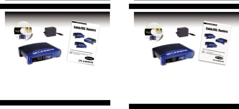
Package Contents for the 4-Port Router (BEFSR41)
Figure 1-1
•One EtherFast Cable/DSL Router with 10/100 4-Port Switch
•One Power Adapter
•One User Guide
•One Setup Wizard CD-ROM
•One TechHelper CD-ROM (not shown)
•One Quick Installation and Registration Card (not shown)
Minimum Requirements
•One External Cable or DSL Modem with Ethernet Port and Network Cable (UTP CAT 5 RJ-45)
•TCP/IP Network Protocol with Ethernet Network Adapter and Cable (UTP CAT 5 RJ-45) Per PC
•Internet Explorer 4.0 or Higher (5.5 Recommended), or Netscape Navigator 4.7 and higher
EtherFast® Cable/DSL Routers
Package Contents for the 1-Port Router (BEFSR11) Package Contents for the 1-Port Router (BEFSR11)
Figure 1-2
•One EtherFast 10/100 1-Port Cable/DSL Router
•One Power Adapter
•One User Guide
•One Setup Wizard CD-ROM
•One TechHelper CD-ROM (not shown)
•One Quick Installation and Registration Card (not shown)
Minimum Requirements
•One External Cable or DSL Modem with Ethernet Port and Network Cable (UTP CAT 5 RJ-45)
•TCP/IP Network Protocol with Ethernet Network Adapter and Cable (UTP CAT 5 RJ-45) Per PC
•Internet Explorer 4.0 or Higher (5.5 Recommended), or Netscape Navigator 4.7 and higher
2 |
3 |
Instant Broadband™ Series
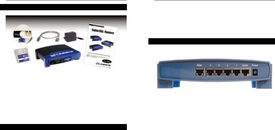
Package Contents for the 3-Port Router (BEFSRU31)
Figure 1-3
•One EtherFast Cable/DSL Router with USB Port & 10/100 3-Port Switch
•One USB Cable
•One 3.5" Floppy Disk for USB Setup
•One Power Adapter
•One User Guide
•One Setup Wizard CD-ROM
•One TechHelper CD-ROM (not shown)
•One Quick Installation and Registration Card (not shown)
Minimum Requirements
•One External Cable or DSL Modem with Ethernet Port and Network Cable (UTP CAT 5 RJ-45)
•TCP/IP Network Protocol with Ethernet Network Adapter and Cable (UTP CAT 5 RJ-45) Per PC
•Internet Explorer 4.0 or Higher (5.5 Recommended), or Netscape Navigator 4.7 and higher
4
EtherFast® Cable/DSL Routers
Chapter 2: Getting to Know the 4-Port EtherFast® Cable/DSL Router
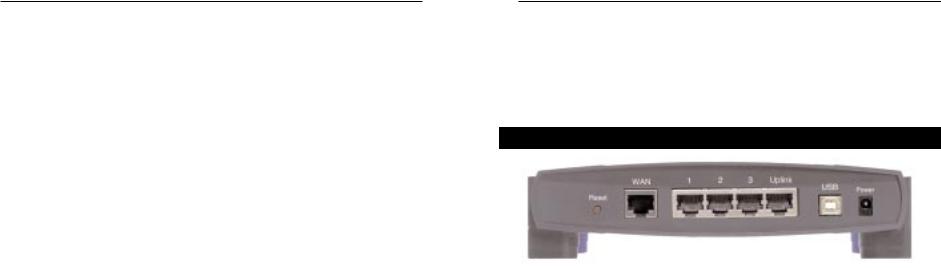
The 4-Port Router’s Rear Panel
Your Router’s ports, where network cables are connected, are located on the rear panel of your Router.
|
Figure 2-1 |
|
WAN |
The WAN (Wide Area Network) port is where you |
|
|
connect your RJ-45 Internet connection through a |
|
|
cable or DSL modem. Your modem connection |
|
|
will not work from any other port. |
|
Ports 1-4 |
These four LAN (Local Area Network) ports con- |
|
|
nect to network devices, such as PCs, print servers, |
|
|
and remote hard drives. If Port 1 is being used, the |
|
|
Uplink port will not work because these two shared |
|
|
ports have internally shared wiring. |
|
Uplink |
The Uplink port is used to expand your network by |
|
|
connecting to another switch or hub. Uplinking to a |
|
|
switch or a hub is done by simply running a cable |
|
|
from the Uplink port to the other device. See the |
|
|
Uplinking: Connecting More Devices to the Router |
|
|
section for more on uplinking. |
|
|
If the Uplink port is being used, Port 1 will not |
|
|
work. |
|
Power |
The Power port is where you will connect the |
|
|
power adapter. |
5 |
|
|
Instant Broadband™ Series
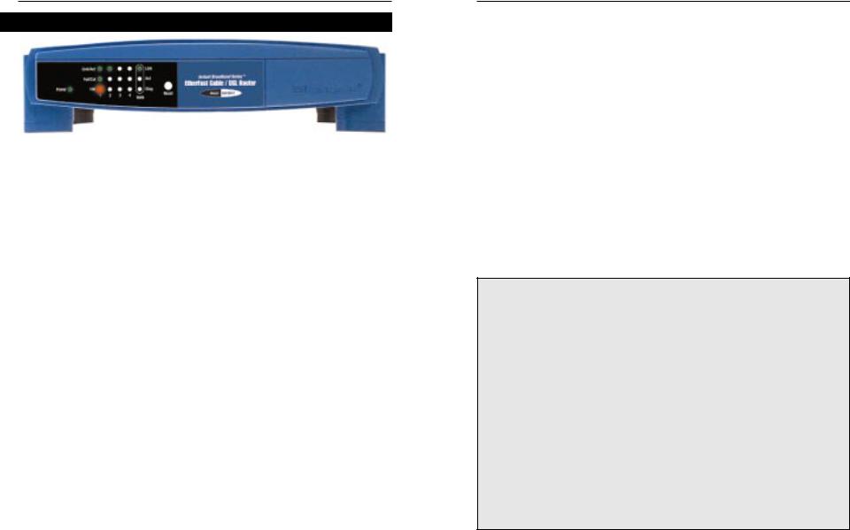
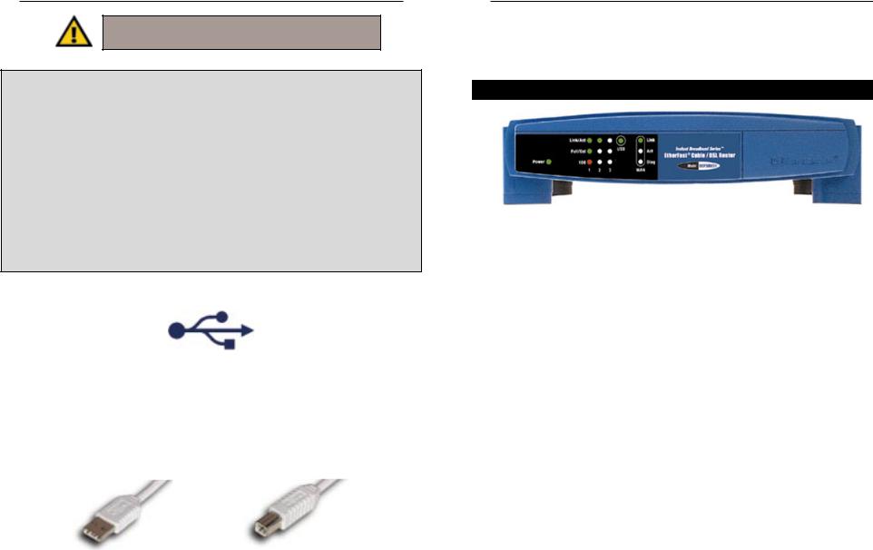
The 4-Port Router’s Front Panel LEDs
|
Figure 2-2 |
Power |
Green. The Power LED lights up when the Router is powered |
|
on. |
Link/Act |
Green. The Link/Act LED serves two purposes. If the LED |
|
is continuously lit, the Router is successfully connected to a |
|
device through the corresponding port (1, 2, 3 or 4). If the |
|
LED is flickering, the Router is actively sending or receiving |
|
data over that port. Port 1 is lit when using the Uplink port. |
Full/Col |
Green. The Full/Col LED also serves two purposes. If this |
|
LED is lit up continuously, the connection made through the |
|
corresponding port is running in Full Duplex mode. If the |
|
LED flickers, the connection is experiencing collisions. |
|
Infrequent collisions are normal. |
|
If this LED flickers too often, there may be a problem with |
|
your connection. See “Appendix A: Troubleshooting” if you |
|
encounter this problem. |
100Orange. The 100 LED lights up when a successful 100 Mbps connection is made through the corresponding port.
If this LED does not light up, then your connection speed is 10 Mbps.
EtherFast® Cable/DSL Routers
The WAN Indicators
Link |
Green. The Link LED lights up when a successful connec- |
|
tion is made between the Router and your broadband device |
|
or network. |
Act |
Green. The Act LED flickers when the Router is sending or |
|
receiving data over the broadband WAN port (to the |
|
Internet). |
Diag |
Red. The Diag LED lights up when the Router goes through |
|
its self-diagnosis mode during every boot-up. It will turn off |
|
upon successful completion of the diagnosis. |
|
If this LED stays on for an abnormally long period of time, |
|
see “Appendix A: Troubleshooting.” |
The Reset Button*
The Reset button can be used in one of two ways.
1.If your Router is having problems connecting to the Internet, press the Reset button for just a moment with a paper clip or a pencil tip. This clears up any jammed connections, and is similar to pressing the Reset button on your PC to reboot it.
2.If you are experiencing extreme problems with your Router and have tried all other troubleshooting measures, press the Reset Button and hold it down until the red Diag LED on the front panel turns on and off completely.
This will restore factory defaults and clear all of the Router’s settings, including the IP addresses you entered.
*The Reset Button is located on the front panel of the 4-Port Router, and the rear panels of the 3- Port Router and the 1-Port Router.
6 |
7 |
Instant Broadband™ Series
Chapter 3: Getting to Know the 1-Port EtherFast Cable/DSL Router
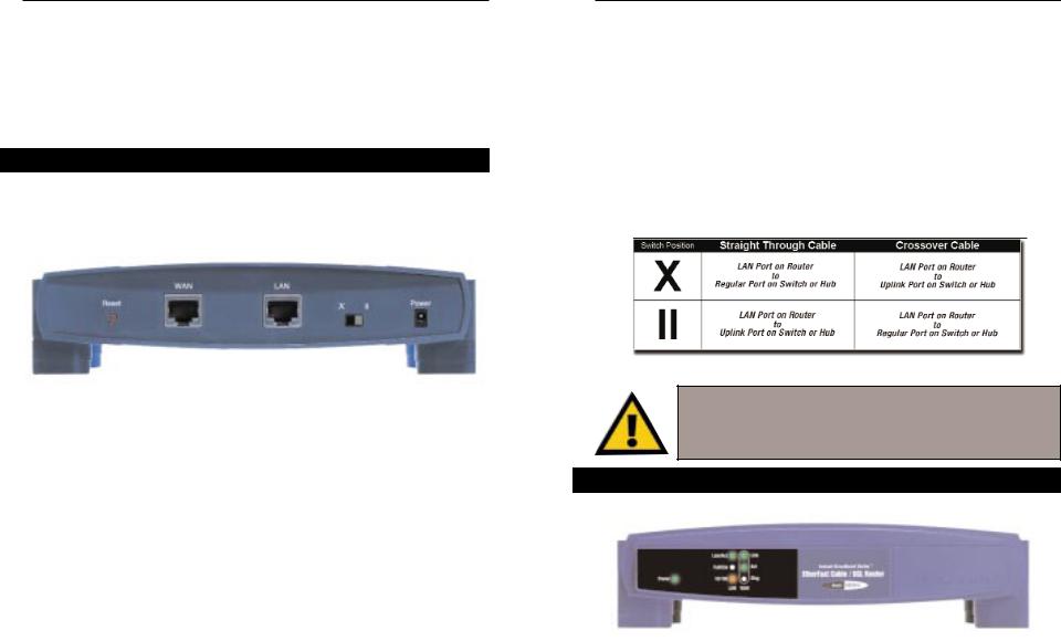
The One-Port Router’s Rear Panel
The rear panel of the Router is where all of the Router’s cabling connections are made, and where you can reset or configure the Router’s LAN port.
|
Figure 3-1 |
WAN |
The WAN (Wide Area Network) port is where you |
|
connect your RJ-45 Internet connection through a |
|
cable or DSL modem. Your modem connection |
|
will not work from any other port. |
LAN |
The LAN (Local Area Network) port is where you |
|
connect your Router to a PC, hub, or switch. If you |
|
have more than one PC, connect an Ethernet hub or |
|
switch to your Router, and then connect your PCs to |
|
that hub or switch. |
Power |
The Power port is where you will connect the |
|
power adapter. |
EtherFast® Cable/DSL Routers
Buttons & Switches
The Reset Button Details on the Reset button are found in the “Getting to Know the 4-Port EtherFast Cable/DSL Router” section.
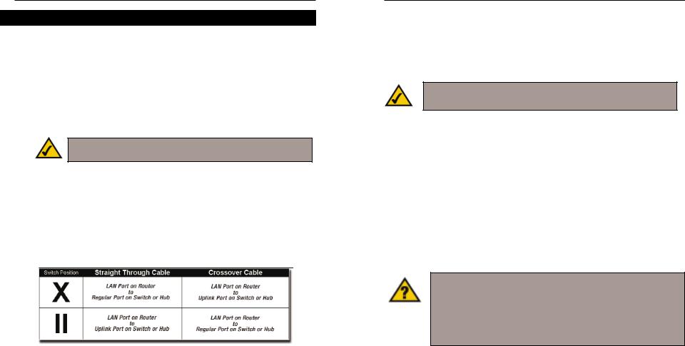
The Crossover Switch
When “uplinking,” or connecting two pieces of network hardware together, such as a hub and a switch, a general rule of thumb is to plug one end of a network cable into a straight-through port, and the other end into a crossover port. Standard ports are straight-through ports, and uplink ports are crossover ports.
T h e 1 - Port
Figure 3-2
Important: The chart in Figure 3-2 is for reference purposes only. Every network is different. If you do not make a connection to a hub or switch by using the settings above, change the position of the Crossover Switch.
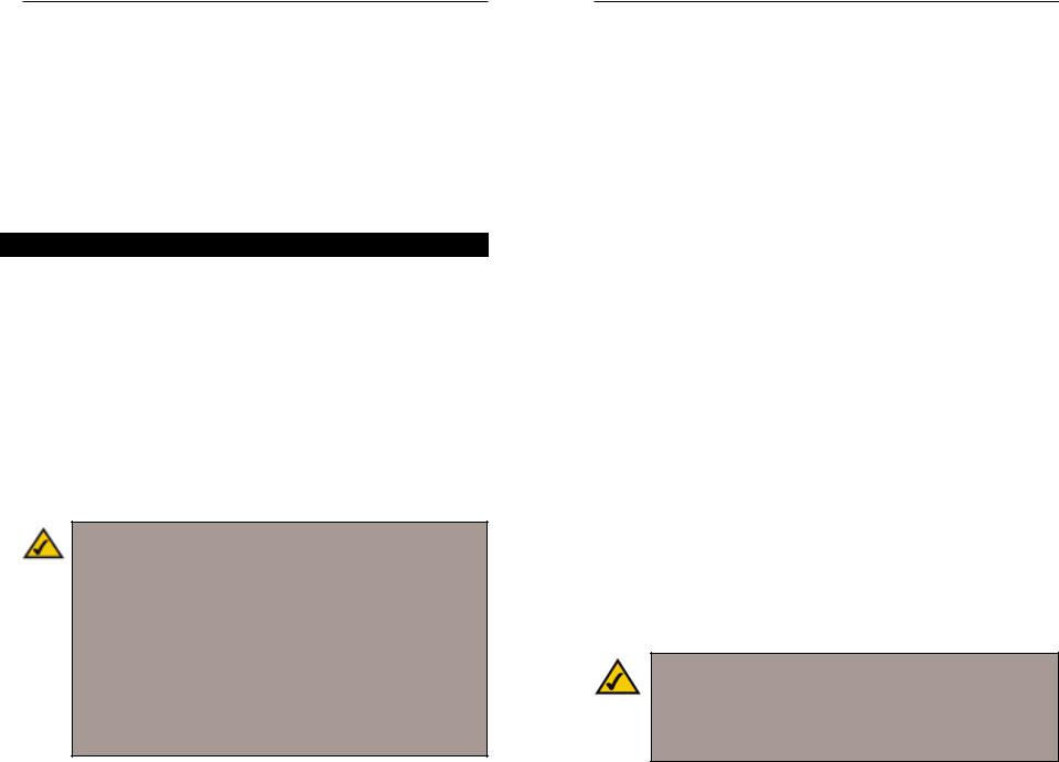
The 1-Port Router’s Front Panel LEDs
Figure 3-3
Power |
Green. The Power LED lights up green when the Router is |
|
powered on. |
8 |
9 |
Instant Broadband™ Series
Link/Act Green. The Link/Act LED serves two purposes. If the LED is continuously lit, the Router is successfully connected to a device through the LAN port. If the LED is flickering, the Router is actively sending or receiving data through the LAN port.
Full/Col Green. The Full/Col LED also serves two purposes. If this LED remains lit, a LAN port connection is being successfully maintained. If the LED flickers, the connection is experiencing collisions. Infrequent collisions are normal.
If this LED flickers too often, there may be a problem with your connection. See “Appendix A: Troubleshooting” if you encounter this problem.
10/100 Orange. The 10/100 LED lights up when a successful 100 Mbps connection is made through the corresponding port.
If a connection is running at 10 Mbps, the 10/100 LED will not light up.
The WAN Indicators
Link |
Green. The Link LED lights up when a successful connec- |
|
tion is made between the Router and your broadband device |
|
or network. |
Act |
Green. The Act LED flickers when the Router is sending or |
|
receiving data over the broadband WAN port. |
Diag |
Red. The Diag LED lights up when the Router goes through |
|
its self-diagnostic mode. It will turn off upon successful |
|
completion of the diagnosis. |
|
If this LED stays on for an abnormally long period of time, |
|
see “Appendix A: Troubleshooting.” |
EtherFast® Cable/DSL Routers
Chapter 4: Getting to Know the 3-Port EtherFast Cable/DSL Router
The 3-Port Router’s Rear Panel Ports
|
Figure 4-1 |
Ports 1-3 |
These three LAN ports connect to your PCs, hubs, |
|
switches, print servers, or any other devices with an |
|
Ethernet port. |
Uplink |
The Uplink port connects to another hub or switch |
|
for port expansion when you run out of open ports |
|
for your network devices. Since the Uplink port and |
|
the standard port right next to it share internal wiring, |
|
you can only use one of the two ports at a time. |
WAN |
The WAN (Wide Area Network) port is where you |
|
connect your RJ-45 Internet connection through a |
|
cable or DSL modem. Your modem connection |
|
will not work from any other port. |
Power |
The Power port is where you will connect the |
|
power adapter. |
USB |
The USB port (Type B - slave) can connect to a |
|
USB-ready PC or a USB hub. This allows you to |
|
enjoy an immediate, plug-and-play connection with- |
|
out even installing a network adapter for your PC. |
|
To work with USB ports, your PC must be running |
|
Windows 98, 2000, Millennium, or XP. |
10 |
11 |
Instant Broadband™ Series
Important: USB ports do not work on PCs running
Windows 95 or Windows NT.
USB Compatibility with Your PC
To use the USB port on the 3-Port Router, you must have Windows 98, 2000, Millennium, or XP installed on your PC. USB cannot run in a Windows 95 or NT environment.
Also, your PC must have a USB port installed and enabled. Some PCs may have a disabled USB port. If your port doesn’t seem to be working, there may be jumpers on the motherboard or a menu option in the BIOS to enable a PC’s USB port.
Other motherboards have USB interfaces, but no ports. You can purchase and install a USB-ready card at your local computer store. See your PC’s user guide for instructions.
This USB icon denotes the presence of a USB port or connector.
Figure 4-2
Your 3-Port Router comes with a USB cable that has two different types of connectors. Type A, the master connector, is shaped like a rectangle and plugs into your PC’s USB port. Type B, the slave connector, resembles a square and connects to the USB port on the rear panel of your Router.
|
|
|
|
|
|
|
|
|
|
|
|
|
|
|
|
|
|
|
|
|
|
|
USB Type A |
|
USB Type B |
|
|
|
|
|
|
|
|
|
|
|
|
|
|
|
|
|
|
|
Figure 4-3 |
|||
EtherFast® Cable/DSL Routers
Buttons
The Reset Button Details on the Reset button are found in the “Getting to Know the 4-Port EtherFast Cable/DSL Router” section.
The 3-Port Router’s Front Panel LEDs
|
Figure 4-4 |
Power |
Green. The Power LED lights up green when the Router is |
|
powered on. |
Link/Act |
Green. The Link/Act LED serves two purposes. If the LED |
|
is continuously lit, the Router is successfully connected to a |
|
device through the corresponding RJ-45 port (1, 2, or 3). If |
|
the LED flickers, then that port is sending or receiving data |
|
to and from the network. |
Full/Col |
Green. The Full/Col LED also serves two purposes. If this |
|
LED is continuously lit, the connection made through the |
|
corresponding port is successfully running in Full Duplex |
|
mode. If the LED is flickering, the connection is experien- |
|
cing collisions. Infrequent collisions are normal. |
|
If this LED flickers too often, there may be a problem with |
|
your connection. See “Appendix A: Troubleshooting” if you |
|
have problems. |
100Orange. The 100 LED lights up when a successful 100 Mbps connection is made through the corresponding port. If this
LED does not light up, then your connection speed is 10 Mbps.
12 |
13 |
|
Instant Broadband™ Series |
USB |
The USB LED lights up when the USB port is successfully |
|
connected to a USB-ready PC or USB hub. |
The WAN Indicators |
|
Link |
Green. The Link LED lights up when a successful connec- |
|
tion is made between the Router and your broadband device |
|
or network. |
Act |
Green. The Act LED flickers when the Router is sending or |
|
receiving data over the broadband WAN port. |
Diag |
Red. The Diag LED lights up when the Router goes through |
|
its self-diagnostic mode. It will turn off upon successful |
|
completion of the diagnosis. |
If this LED stays on for an abnormally long period of time, see “Appendix A: Troubleshooting.”
EtherFast® Cable/DSL Routers
Chapter 5: Connecting the Cable/DSL Router to Your Network
Overview
Unlike a hub or a switch, the Cable/DSL Router’s setup consists of more than simply plugging hardware together. Since the Router acts as a DHCP server, you will have to set some values for the Router and also configure your networked PCs to accept the IP addresses that the Router assigns them.
If you use a static IP address to connect to the Internet, you will need the following data from your Internet Service Provider (ISP) to install the Router:
• Your broadband-configured PCs’ Computer Name and Workgroup Name
• Your broadband-configured PCs’ fixed Internet IP Address
• Your Subnet Mask |
} |
Only if applicable |
• Your Default Gateway |
|
|
• Your Primary DNS Server IP address(es) |
|
|
The installation technician from your ISP should have left this information with you after installing your broadband connection. If not, you can call your ISP to request the data. Otherwise, most ISPs will automatically assign an IP address and other information to connect to the Internet.
Once you have the above values, you can begin the installation and setup of your EtherFast Cable/DSL Router.
LANs and WANs
Simply put, a router is a network device that connects two networks together.
In this instance, your EtherFast Cable/DSL Router connects your Local Area Network (LAN), or the group of PCs in your home or office, to the Wide Area Network (WAN), that is, the Internet. Your Router processes and regulates the data that travels between these two networks.
Think of your Router as a network device with two sides: the first side is made up of your private Local Area Network (LAN) of PCs, which this User Guide sometimes calls the “internal LAN.” The other, public side is the Internet, or the Wide Area Network (WAN), outside of your home or office.
14 |
15 |
Instant Broadband™ Series
Your Router’s firewall (NAT) protects your network of PCs so users on the public, Internet side cannot “see” your PCs. This is how your internal LAN, or network, remains private. The Router protects your network by inspecting the first packet coming in from the WAN port before delivery to the final destination on the LAN port. The Router inspects Internet port services like the web server, ftp server, or other Internet applications, and, if allowed, it will forward the packet to the appropriate PC on the LAN side.
Remember that your Router’s ports connect to two sides: your 10/100 LAN port(s) and the Internet WAN port. The LAN port(s) transmit data at 10 Mbps or 100 Mbps, whereas the broadband port, or WAN port, transmits data at 10 Mbps.
IP Addressing: A Quick Lesson
What’s an IP Address?
IP stands for Internet Protocol. Every device on an IP-based network, including PCs, print servers, and routers, requires an IP address to identify its “location,” or address, on the network. This applies to both the WAN and LAN connections.
There are two ways of assigning an IP address to your network devices.
Static IP Addresses
A static IP address is a fixed IP address that you assign manually to a PC or other device on the network. Since a static IP address remains valid until you disable it, static IP addressing insures that the device assigned it will always have that same IP address until you change it. Static IP addresses are commonly used with network devices such as server PCs or print servers.
Note: Since your Router is a device that connects two networks, it needs two IP addresses—one for the LAN side, and one for the WAN side. In this User Guide, you’ll see references to the “WAN IP address” and the “LAN IP address.”
Since the Router has firewall security (NAT), the only IP address that can be seen from the Internet for your network is the Router’s WAN IP address.
However, even this WAN IP address for the Router can be blocked, so that your Router and network seem invisible to the Internet—see the Blocking WAN Requests description under IP Filtering in “Chapter 8: The Cable/DSL Router’s Web-based Utility.”
EtherFast® Cable/DSL Routers
If you use your Router to share your cable or DSL Internet connection, contact your ISP to find out if they have assigned a static IP address to your account. If so, you will need that static IP address when configuring your Router. You can get the information from your ISP.
Dynamic IP Addresses
A dynamic IP address is automatically assigned to a device on the network, such as PCs and print servers. These IP addresses are called “dynamic” because they are only temporarily assigned to the PC or device. After a certain time period, they expire and may change. If a PC logs on to the network (or the Internet) and its dynamic IP address has expired, the DHCP server will assign it a new dynamic IP address.
For DSL users, many ISPs may require you to log on with a user name and password to gain access to the Internet. This is called Point to Point Protocol over Ethernet (PPPoE). PPPoE is similar to a dial-up connection but does not have a phone number to dial into, and PPPoE is a dedicated high-speed connection. PPPoE also will provide the Router with a dynamic IP address to establish a connection to the Internet.
DHCP (Dynamic Host Configuration Protocol) Servers
PCs and other network devices using dynamic IP addressing are assigned a new IP address by a DHCP server. The PC or network device obtaining an IP address is called the DHCP client. DHCP frees you from having to assign IP addresses manually every time a new user is added to your network.
DHCP servers can either be a designated PC on the network or another network device, such as the Cable/DSL Router. The Router’s WAN port, by default, is set as a DHCP client.
By factory default, a DHCP server (LAN side) is enabled on your Router. If you already have a DHCP server running on your network, you must disable one of the two DHCP servers. If you run more than one DHCP server on your network, you will experience network errors, such as conflicting IP addresses. To disable DHCP on your Router, see the DHCP section in “Chapter 8: The Cable/DSL Router’s Web-based Utility.”
Note: Even if you assign a static IP address to a PC, other PCs can still use DHCP’s dynamic IP addressing, as long as the static IP is not within the DHCP range of the LAN IP Address.
If the dynamic IP addressing fails to provide a dynamic IP address for any reason, please refer to “Appendix A: Troubleshooting.”
16 |
17 |
Instant Broadband™ Series
Connecting Your Hardware Together and Booting Up
1.Before you begin, make sure that all of your hardware is powered off, including your Router, PCs, hubs, switches, and the cable or DSL modem.
2.A. If you have the 4-Port Cable/DSL Router, connect one end of a network cable to one of the LAN ports (labeled 1, 2, 3, or 4) on the back of the Router, and the other end into a standard port on a network device, e.g., a PC, print server, hub, or switch. See “Appendix E: Twisted-Pair Cabling” for details on network cabling.
Note: A standard port is any port other than the WAN port and the Uplink port on the Router. It’s a straight-through port.
Repeat the above step to connect more PCs or network devices to the Router.
2.B. If you have the 1-Port Router, connect one end of a network cable to the LAN port on the back of the Router, and the other end into a port on a network device, e.g., a PC, hub, or switch. If you are using Port 4 to connect to a PC, set the Crossover switch to straight-through mode ( || ). If you are connecting the Router to a hub or switch, please refer to the chart shown in Figure 5-1 when setting the Crossover Switch.
Figure 5-1
2.C. If you have the 3-Port Cable/DSL Router, connect one end of a network cable from the Router’s LAN ports (labeled 1, 2, or 3) to a network adapter port on a PC, hub, switch, or other network device.
The 3-Port Router features one USB plug-and-play port that connects instantly to any USB-ready PC or USB hub. This allows you to connect to and access your Router without even installing any network adapter cards.
EtherFast® Cable/DSL Routers
3.Connect the network cable from your cable or DSL modem to the WAN port on your Router’s rear panel. This is the only port that will work for your modem connection.
4.Connect the power adapter to the Power port on the rear panel of the Router, and then plug the power adapter into a power outlet.
Note: It is highly recommended that you plug your Router’s power adapter into a power strip with surge protection.
•The Power LED on the front panel will light up green as soon as the power adapter is connected properly.
•The Diag LED will light up red for a few seconds when the Router goes through its self-diagnostic test. This LED will turn off when the self-test is complete.
5. Power on the cable or DSL modem.
6.Press the Reset button on the Router’s front panel with a paper clip or a pencil. Hold the button in until the Diag LED lights up and then turns off. This will restore the Router’s factory default settings.
Have you checked that the Link/Act LEDs for all your LAN connections and the Link LED for your WAN connection light up?
If all of your Link LEDs are not lighting up, make sure that all your cables are securely plugged in, and that all of your hardware is powered on properly.
The Router’s hardware installation is now complete.
18 |
19 |
Instant Broadband™ Series
Uplinking: Connecting More Devices to Your Router
If your Router’s LAN ports are all full and you still have PCs and/or devices to connect, connect a hub or a switch to your Router using a network cable.
To do so, use the Router’s Uplink port to connect to a standard port on a hub or switch. If you have a PC/device connected to the port right next to the Uplink port (on the 3- and 4-Port Routers), disconnect that PC/device and plug it into an open port on the new hub or switch.
Since the Uplink port shares internal wiring with the port right next to it, you can only use one of these two ports at a time; these ports are called shared ports.
If your new hub or switch also has an Uplink port, it too can be uplinked when you run out of ports, and so on.
Use the Router’s Uplink port to connect to a standard port on a hub or switch. This leaves you with new, open ports on the hub or switch, to which you can add more PCs and/or network devices.
See your nearest Linksys retailer or visit www.linksys.com for complete product lines of 10/100 Mbps hubs and switches.
EtherFast® Cable/DSL Routers
Chapter 6: Installing the
BEFSRU31’s USB Port Drivers
Use the enclosed USB cable to connect your PC to the Router; the Type A end connects to your PC’s USB port, while Type B connects to the Router’s USB port. Now that all of your Router’s hardware is connected together, you must enable the PC that will connect to the Router through its USB port.
Since your USB connection acts as a network adapter for your PC, there’s no need for you to install a network adapter for that PC. Just follow the directions below to enable your PC’s USB connection to the Router:
•If you are running Windows 98, continue on this page, below.
•For other Windows operating systems, please refer to the appropriate section as listed in the Table of Contents.
Note: After you finish this configuration, make sure that TCP/IP is installed on your PC(s). For instructions on installing TCP/IP, see “Appendix D: Installing the TCP/IP Protocol.”
You can also connect your Router’s USB port to other USB devices besides USB-ready PCs, such as a USB hub using a USB cable.
Installing the Windows 98 Driver
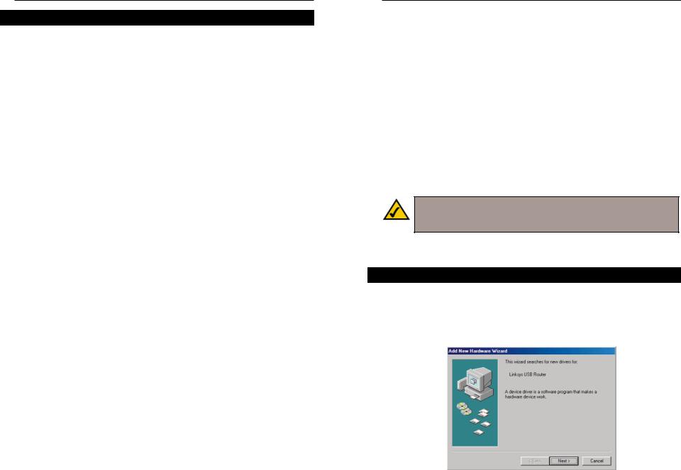
1.With the Router connected to your PC’s USB port using a USB cable, start up your PC in Windows 98 and insert the driver disk.
2.Windows will display a message notifying you that it has detected new hardware. Click the Next button.
Figure 6-1
20 |
21 |

Instant Broadband™ Series
3.Select Search for the best driver for your device (Recommended). Click the Next button.
Figure 6-2
4.Insert the driver disk into the floppy drive, and select Floppy disk drives only. Click the Next button to start the search for your driver.
Figure 6-3
EtherFast® Cable/DSL Routers
5.The Hardware Wizard will search the floppy, and a new window will appear, notifying you that Windows is now ready to install the best driver for this device. Click the Next button to continue.
Figure 6-4
6.Windows will begin copying the files to your PC. Do not click the Cancel button or press the Esc key during this process.
If Windows asks for your Windows operating system files before copying, direct your PC to the location of those files, e.g, c:\windows\options\cabs, or D:\Win98 (if “D” is the letter of your CD-ROM drive).
Figure 6-5
22 |
23 |
Instant Broadband™ Series
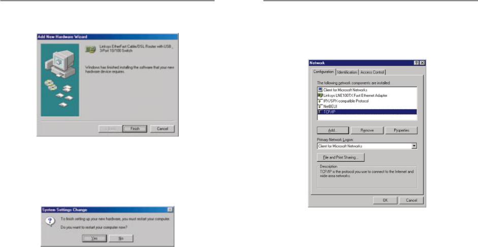
7.Windows will notify you that it has completed copying the driver files to your PC. Click the Finish button to complete the USB driver installation.
Figure 6-6
8.Windows will ask you if you want to restart your PC. Click the Yes button so your new installation will take effect.
If it does not ask you to restart your computer, click the Start button, and select Shut Down. Then select Restart and click the Yes button.
Figure 6-7
EtherFast® Cable/DSL Routers
9.When your PC is finished restarting, click the Start button, and select Settings, Control Panel, and Network. Make sure that TCP/IP is installed for your PC as shown on the screen in Figure 6-8. By default, Windows 98 has TCP/IP installed. If TCP/IP is not installed, please go to “Appendix D: Installing the TCP/IP Protocol” for instructions on installation.
Figure 6-8
Your USB installation is now complete.
Go to “Chapter 7: Configuring Your Network with the Cable/DSL Router.”
24 |
25 |
Instant Broadband™ Series
Installing the Windows 2000 Driver
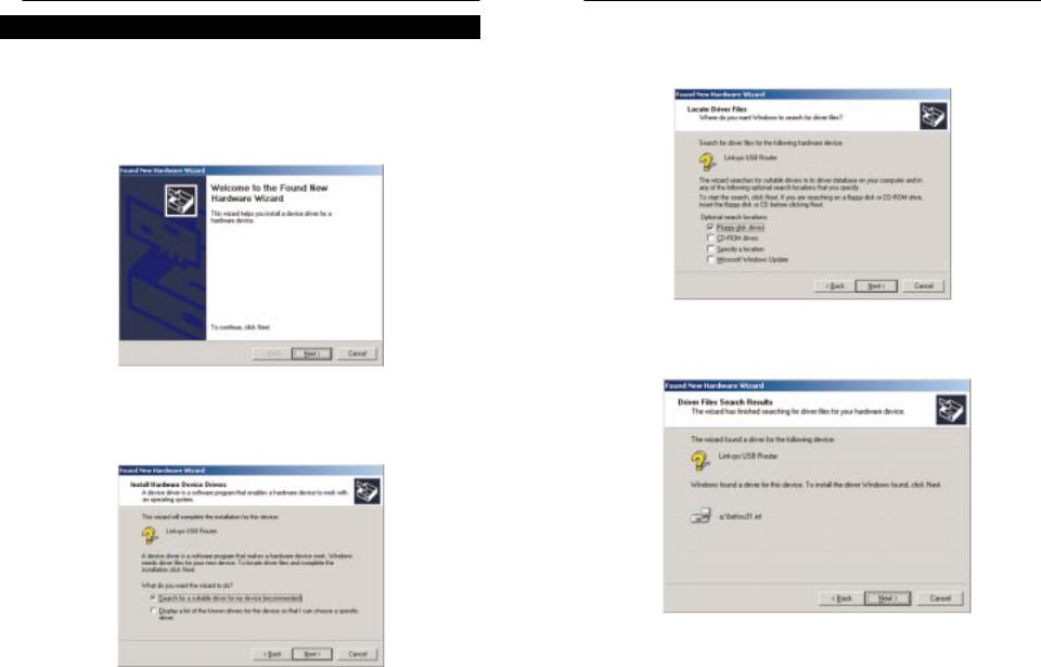
1.With the Router connected to your PC’s USB port using a USB cable, start up your PC in Windows 2000 and insert your driver disk. Windows will show a message notifying you that the PC has found new hardware. Windows’ Hardware Wizard will show a message to notify you that it is ready to start installing the driver files to your PC. Click the Next button.
Figure 6-9
2.Select Search for a suitable driver for my device (Recommended) and click the Next button.
Figure 6-10
EtherFast® Cable/DSL Routers
3.Insert the driver disk into the floppy drive, and when Windows asks you where to search for driver files, select Floppy disk drives only. Click the Next button.
Figure 6-11
4. Windows will show a message notifying you that it has found the driver files. Click the Next button.
Figure 6-12
26 |
27 |
Instant Broadband™ Series
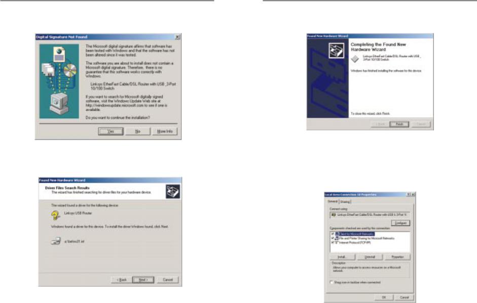
5.When the Digital Signature Not Found screen appears, Windows will ask you if you want to continue with the installation. Click the Yes button.
Figure 6-13
6. Click the Next button for Windows to copy the driver files to your PC.
Figure 6-14
EtherFast® Cable/DSL Routers
7.Windows will display a message notifying you that it has finished installing the driver files on your PC. Click the Finish button to complete the USB driver installation.
Figure 6-15
8.Go to the Start button, and select the Settings option. Then select the
Network and Dial-up Connections option, and click the Local Area Connection icon. Click the Properties button to display the screen below. Highlight Internet Protocol (TCP/IP) as shown below, and click on the Properties button. Make sure that TCP/IP is set to Obtain an IP Address Automatically.
Figure 6-16
Your USB installation is now complete.
Go to “Chapter 7: Configuring Your Network with the Cable/DSL Router.”
28 |
29 |
 Loading...