


INSTALLATION AND OWNER’S MANUAL
M50JF & M50JH
M-SERIES JACKSHAFT COMMERCIAL
VEHICULAR DOOR OPERATORS
As of date of manufacture, meets all ANSI/UL 325 Safety Requirements for Vehicular door operators
Serial #:
Date Installed:
Your Dealer:
100771
READ THIS MANUAL CAREFULLY BEFORE INSTALLATION OR USE. SAVE THIS MANUAL!
TABLE OF CONTENTS |
2 |
Jackshaft Operator Applications.................................................................................. |
3 |
Preparation .................................................................................................................... |
4 |
Figure 1 - Component Identification Pictorial.............................................................. |
4 |
Important Installation Warnings (Things To Do Before & During Installation) ......... |
5 |
Table 1 - Component Identification Listing.................................................................. |
5 |
Installation Instructions ............................................................................................. |
6-7 |
Figure 2 - Operator Footprint........................................................................................ |
6 |
Figure 3 - Release/Hand Chain Wall Bracket Installation ........................................... |
7 |
Figure 4 - Mounting Positions ...................................................................................... |
7 |
Figure 5 - Operator Dimensions - Model M50JF.......................................................... |
8 |
Figure 5A - Operator Dimensions - Model M50JH....................................................... |
9 |
Setting The Limits ....................................................................................................... |
10 |
Figure 6 - Limit Adjustment ........................................................................................ |
10 |
Electrical Wiring Instructions ..................................................................................... |
11 |
Figure 7 - Pneumatic Door Edge Installation............................................................. |
12 |
Figure 8 - Field Wiring................................................................................................. |
12 |
Operation and Adjustment Instructions ............................................................... |
13-17 |
Important Safety Instructions for Owner ................................................................... |
13 |
Wiring Terms ............................................................................................................... |
14 |
Clutch Adjustment....................................................................................................... |
15 |
Brake Adjustment........................................................................................................ |
16 |
Testing ......................................................................................................................... |
16 |
Maintenance ................................................................................................................ |
17 |
Wiring Diagram............................................................................................................ |
18 |
Wiring Schematic ........................................................................................................ |
19 |
Warranty....................................................................................................................... |
20 |
READ THESE STATEMENTS CAREFULLY AND FOLLOW THE
INSTRUCTIONS CLOSELY.
The Warning and Caution boxes throughout this manual are there to protect you and your equipment. Pay close attention to these boxes as you follow the manual.
|
|
|
|
|
|
|
|
|
|
|
WARNING |
|
CAUTION |
|
WARNING |
|
CAUTION |
||||
|
|
|
|
|
|
|
||||
Indicates a MECHANICAL |
|
Indicates a MECHANICAL hazard |
|
Indicates an ELECTRICAL |
Indicates an ELECTRICAL hazard |
|||||
hazard of INJURY OR |
|
of DAMAGE to your operator or |
|
hazard of INJURY OR |
|
of DAMAGE to your operator or |
||||
DEATH. Gives instructions |
|
equipment. Gives instructions to |
|
DEATH. Gives instructions |
|
equipment. Gives instructions to |
||||
to avoid the hazard. |
|
avoid the hazard. |
|
to avoid the hazard. |
|
avoid the hazard. |
||||
|
|
|
|
|
|
|
|
|
|
|

3 |
PRODUCT FEATURES |
The purpose of this booklet is to provide assembly, installation and operation information concerning Allstar Model M50JF & M50JH Commercial Vehicular Garage Door Operators and related Accessory Products.
NOTICE
IT IS IMPORTANT THAT THIS INSTRUCTION MANUAL BE READ AND UNDERSTOOD COMPLETELY BEFORE INSTALLATION OR OPERATION IS ATTEMPTED. IT IS INTENDED THAT THE INSTALLATION OF THIS UNIT WILL BE DONE ONLY BY PERSONS TRAINED AND QUALIFIED IN THE INSTALLATION, ADJUSTMENT AND SERVICE OF COMMERCIAL OVERHEAD DOORS AND DOOR OPERATORS AND BY QUALIFIED ELECTRICIANS.
NOTICE
THE IMPORTANT SAFEGUARDS AND INSTRUCTIONS IN THIS MANUAL CANNOT COVER ALL POSSIBLE CONDITIONS AND SITUATIONS WHICH MAY OCCUR DURING ITS USE. IT MUST BE UNDERSTOOD THAT COMMON SENSE AND CAUTION MUST BE EXERCISED BY THE PERSON(S) INSTALLING, MAINTAINING AND OPERATING THE EQUIPMENT DESCRIBED HEREIN. DO NOT USE THIS EQUIPMENT FOR ANY OTHER THAN ITS INTENDED
PURPOSE - OPERATING OVERHEAD COMMERCIAL VEHICULAR GARAGE DOORS.
STANDARD FEATURES:
Limit Switches: Driven limit switches, easily adjusted over a wide range. The motor may be removed without affecting the limit switch adjustments
Manual Release: Permits manual operation of the door in the event of a power failure. The Model M50JH is equipped with a chain hoist to aid in manual operation.
Control Circuit: Standard three button open, close and stop. 24 Volts AC.
Connections For Auxiliary Entrapment Protection Devices: Use with foam or pneumatic reversing door edge components or a photoelectric beam (across the opening) device.
Constant Contact To Close: Feature can be activated by simply removing 2 wires from the terminal strip.
Momentary Contact To Close: Standard operation.
MODEL M50JF & M50JH OPERATOR APPLICATIONS:
Jackshaft operators are intended for commercial and industrial use to raise or lower sectional overhead doors by chain coupling or direct coupling to the door shaft. Jackshaft operators are suitable where all or part of the door remains in a vertical position when fully open such as doors with at least 18 inches of lift clearance or full vertical lift doors. M Series Jackshaft operators may also be used with certain roll up service doors and grills when appropriately sprocketed (consult factory).
A jackhaft operator DOES NOT LOCK THE DOOR IN ITS CLOSED POSITION. However, because the cross-header shaft is prevented by the operator from turning, the torsion springs provide no assistance in lifting the door should an attempt be made to raise it manually.
The M Series jackshaft operators are used in the following applications:
-Intermittent Duty, Limited Cycle Commercial installations only
-Rate of operation shall not exceed 10 cycles of opening and closing per hour, maximum 60 cycles per day.
-Indoor Use Only
-Up to 14 foot high doors with a maximum area of 196 square feet, maximum area slightly higher for lighter doors - consult factory
-Use with foam/pneumatic reversing door edge or photoelectric device - REQUIRED where the 3-button station is out of sight of the door, or any other automatic, remote or manual control is used to activate the door
OPTIONAL FEATURES:
Digital Radio Controls: Open, Close and Stop operation. Radio units are available to control up to 27 doors from one transmitter
Digital Timer to Close: Adjustable from 0 to 17 minutes in one second intervals.
Keyless Entry System: Connection terminals provided for hard wired or wireless keyless entry systems.
 PREPARATION
WARNING
ELECTRIC DOOR OPENERS ARE DESIGNED FOR DOORS IN GOOD WORKING CONDITION, PROPERLY COUNTERBALANCED AND PROPERLY ADJUSTED IN ACCORDANCE WITH THE DOOR MANUFACTURER'S INSTALLATION INSTRUCTIONS.
Before starting the installation of the operator, the door must be in good working condition and properly counterbalanced. Inspect the door and track for loose or missing hardware. Test the door manually for balance and ease of operation. Lubricate door hinges and rollers. If necessary, employ a qualified technician to adjust the springs for proper counterbalance of the door.
Stops should be installed at the top end of each track to prevent the possibility of the door rollers moving beyond the ends of the track.
If the cross header shaft is made from hollow tubing rather than solid rod, it is recommended that it be plugged with a short length of solid bar for a more secure installation of the shaft sprocket or flange coupler.
Before removing the operator powerhead from the shipping
4
carton, inspect the nameplate on the cover of the operator control box to verify that it is the correct model for the intended application and that the voltage and phase are in accordance with electrical power provided at the job site. If the operator was ordered with the optional chain hoist, Model M50JH, see that it is so equipped. A chain hoist CANNOT be added in the field.
Warning: Rope off the area to keep personnel and vehicles clear of the door and floor space in the vicinity of the operator during the installation.
WARNING
SPRINGS ARE SUBJECT TO VERY HIGH FORCES AT ALL TIMES AND ADJUSTMENTS MUST BE MADE ONLY BY A QUALIFIED PROFESSIONAL DOOR INSTALLER.
WARNING
REMOVE OR DISABLE ANY LOCKING DEVICES FROM DOOR AND REMOVE ALL ROPES
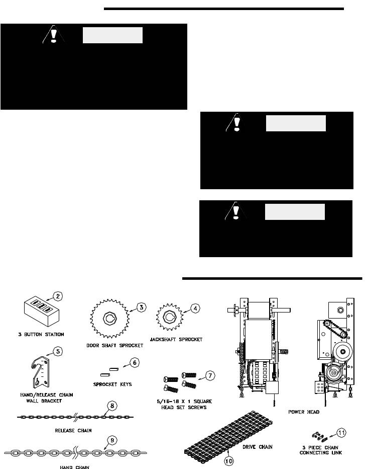
 COMPONENT IDENTIFICATION
107170-2 |

5 |
IMPORTANT INSTALLATION NOTES |
TO REDUCE THE RISK OF SEVERE INJURY WARNING OR DEATH: READ AND FOLLOW ALL
INSTALLATION INSTRUCTIONS!
♦Install only on a properly balanced garage door. An improperly balanced door could cause severe injury. Have a qualified service person make repairs to cables, spring assemblies and other hardware before installing the opener.
♦Remove all ropes and remove or make inoperative all locks (unless mechanically and/or electrically interlocked to the power unit) that are connected to the garage door before installing the opener.
♦Lightweight doors (fiberglass, aluminum etc.) must be reinforced to avoid door damage. Check the door manufacturer’s instruction manual for a bracing procedure or the availability or a Reinforcement Kit.
♦Allstar Model M50JF and M50JH are Commercial Vehicular Door Operators and as such are NOT recommended for pedestrian traffic. In installations where it is known that pedestrians will be nearby ensure a pedestrian door is available for entrance and exit to the building. In addition YOU MUST install an auxiliary entrapment protection device (reversing door edge or photoelectric beam device) as part of the compete operator system.
♦Connect an auxiliary entrapment protection device (reversing edge or photoelectric device across the door opening). A device of this type is STRONGLY ADVISED FOR ALL commercial operator installations. An auxiliary entrapment protection device is REQUIRED when the three button control station is out of sight of the door or any other automatic or manual control is used.
♦Install the opener at least 8 feet or more above the floor.
♦Do not connect the opener to the source of power until instructed to do so.
♦Locate the control station:
♦a) within sight of the door and;
♦b) at a minimum height of five feet above
♦the floor and;
♦c) away from all moving parts of the
♦door.
♦Do not overtighten the clutch adjustment to compensate for a poorly working door.
♦Securely attach any WARNING signs or placards to either the door or above the control station as directed (see page 11).
♦After installing the opener, all safety features must be tested for proper operation (see page 16).
COMPONENT IDENTIFICATION LISTING 
ITEM # |
PART# |
DESCRIPTION |
QUAN. |
ITEM # |
PART# |
DESCRIPTION |
QUAN |
||
|
1 |
|
Operator Power Head |
1 |
6 |
100413 |
1/4” Square Key |
2 |
|
2 |
E031 |
3 Button Station |
1 |
7 |
F119 |
5/16-18 x 1 Square Head Set Screw |
4 |
||
3 |
X062 |
30 |
Tooth Sprocket, 1” Bore, 1/4 Key |
1 |
8 |
X249 |
Release Chain |
AR |
|
4 |
X061 |
20 |
Tooth Sprocket, 1” Bore, 1/4 key |
1 |
9 |
100315 |
#3 Hand Chain - Precut to 26 Ft. |
1 |
|
5 |
105193 |
Release/Hand Chain Wall Bracket |
1 |
10 |
X239 |
Drive Chain to Door Shaft, 4 Ft. |
1 |
||
—— AR - As Required |
|
|
|
|
|
|
|
||
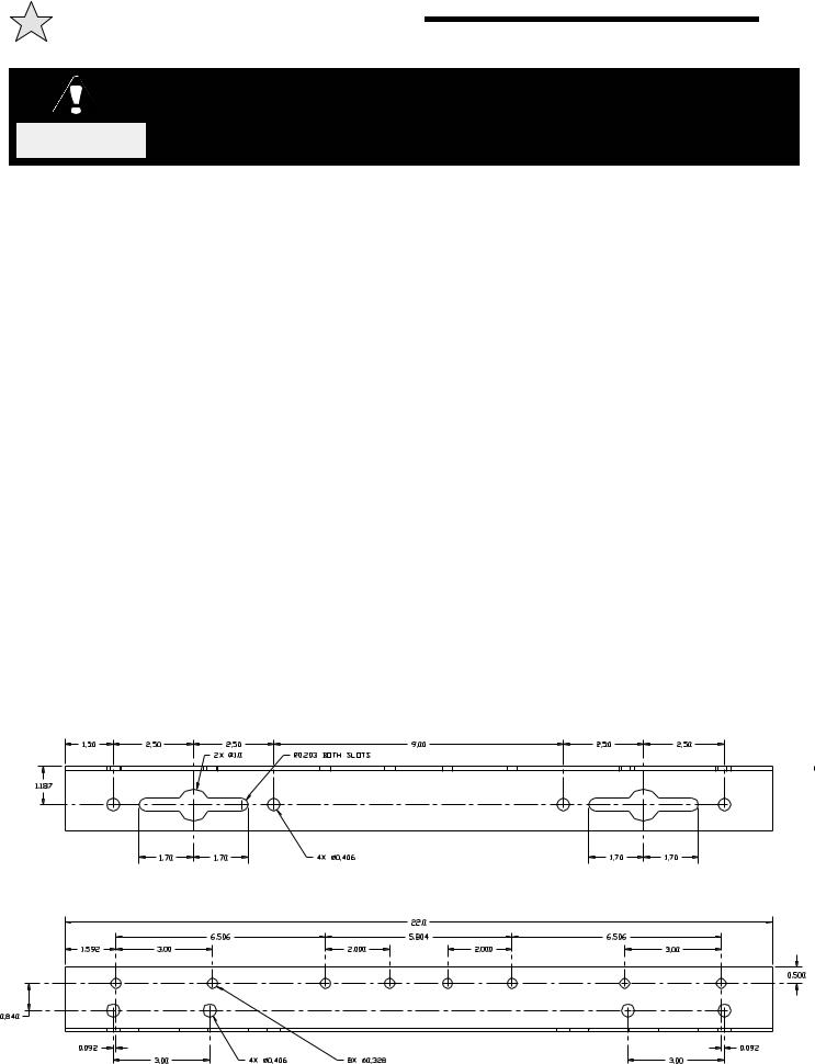
INSTALLATION INSTRUCTIONS |
6 |
|
|
SPRINGS, PULLEYS, CABLES AND MOUNTING HARDWARE USED TO |
|
|
BALANCE YOUR GARAGE DOOR ARE UNDER EXTREME TENSION AT ALL |
|
WARNING |
TIMES AND CAN CAUSE SEVERE INJURY OR DEATH IF DISTURBED. |
|
DO NOT ATTEMPT ADJUSTMENT. |
|
|
Figure 4, page 7 illustrates several positions suitable for mounting the operator; right hand or left hand, either wall mount or ceiling mount.
CHAIN COUPLING MOUNTING
Refer to Figure 2 (at right), Figure 1, page 4 and Figures 5 and 5A, pages 8 and 9 for component identification and the operator mounting slot locations. Place the sprockets [ 3 ] and [ 4 ] on the chosen side of the torsion shaft of the door and on the corresponding end of the output shaft of the operator. The sprockets should be kept as close as possible to the bearings. Fasten the connecting link to each end of the door chain and loop the chain over the sprocket [ 3 ] on the torsion shaft. Temporarily suspend the operator in its mounting position using the chain over the sprocket [ 4 ] at one end of the jackshaft and a rope or chain at the mid point (to support the operator weight). With the chain tight and straight and the jackshaft parallel with the torsion shaft, trace the mounting slot on the mounting surface then lower the operator to the floor.
through the wall, then use lag bolts to fasten the operator to the mounting surface. Locate the four holes within the tracings of the slots made in the previous step at the positions which will allow for adjust-ment of the chain tension. After drilling the mounting holes and installing lag shields, if necessary, bolt the operator to the mounting surface but do not completely tighten the bolts at this time. Check the alignment of the sprockets, adjust their positions on the shafts if necessary and tighten the set screws securely on both sprockets. pulling downward on the operator to remove slack from the chain, tighten the four mounting bolts.
Inspect the installation. There should be no slack in the chain but neither should it be under severe tension which might shorten the life of the bearings. If there is any flexibility in the system due to construction of the surface supporting the operator or noticeable deflection of the door shaft, it is advisable to install a shaft support between the operator jackshaft and the door shaft to prevent the loss of limit settings due to the possibility of the chain jumping over the sprocket teeth. Shaft supports are available from the factory.
IT IS ESSENTIAL THAT THE SURFACE SUPPORTING THE OPERATOR BE RIGID AND SECURE. FAILURE TO PROVIDE A FIRM MOUNTING SURFACE WILL RESULT IN DAMAGE TO THE DOOR TORSION SHAFT AND THE PREMATURE FAILURE OF THE OPERATOR.
If the construction permits, the operator should be mounted with 3/8 inch diameter bolts through the wall. If it is not feasible to go
BEFORE PROCEEDING WITH THE OPERATOR INSTALLATION AND SETTINGS, MAKE A FINAL CHECK FOR TIGHTNESS OF ALL MOUNTING HARDWARE AND SET SCREWS.
Proceed to “Chain Hoist and Floor Disconnect Installation”.
107864
Figure 2
 Loading...