


Digital Keyless Entry System
Installation and Programming Instructions
(760) 438-7000 • FAX (760) 438-7043
USA & Canada (800) 421-1587 & (800) 392-0123
Toll Free FAX (800) 468-1340
www.linearcorp.com

CONTENTS |
|
INTRODUCTION . . . . . . . . . . . . . . . . . . . . . . . . . . |
. 2 |
SPECIFICATIONS . . . . . . . . . . . . . . . . . . . . . . . . . . |
2 |
FEATURES . . . . . . . . . . . . . . . . . . . . . . . . . . . . . . |
2 |
COMPONENT LOCATIONS . . . . . . . . . . . . . . . . . . . . . . |
3 |
WIRING DIAGRAM . . . . . . . . . . . . . . . . . . . . . . . . . |
3 |
INSTALLATION . . . . . . . . . . . . . . . . . . . . . . . . . . . |
4 |
FACTORY DEFAULTS . . . . . . . . . . . . . . . . . . . . . . . . . |
6 |
BASIC PROGRAMMING . . . . . . . . . . . . . . . . . . . . . . . |
6 |
PROGRAMMING OPTIONS . . . . . . . . . . . . . . . . . . . . . |
7 |
ACCESSKEY OPERATION . . . . . . . . . . . . . . . . . . . . . . |
10 |
MANAGER’S ENTRY CODE LOG . . . . . . . . . . . . . . . . . . |
11 |
LINEAR LIMITED WARRANTY . . . . . . . . . . . . . . . . . . . |
12 |
FCC NOTICE . . . . . . . . . . . . . . . . . . . . . . . . . . . . |
12 |
INTRODUCTION
Linear’s AccessKey is a digital keyless entry system designed for access control applications. The keypad is housed in a rugged cast aluminum enclosure that can be mounted to a pedestal or bolted directly to a wall. The die-cast keys have bright, easy-to-read yellow graphics.
Up to 480 entry codes, from 1 to 6 digits in length, can be programmed. They can activate either, or both, of the relay outputs. Relay #1 has a 5 Amp capacity. Relay #2 has a 1 Amp capacity.
Two LED indicators show the status of the entry system. The left LED lights red to indicate power, then turns green when access is granted. The right LED lights yellow when the keypad is in “lockout” condition (from too many incorrect code entries). The keypad’s courtesy light illuminates the keys for two minutes after any key is pressed. An internal sounder beeps when each key is pressed.
The DOOR SENSE/INHIBIT input can be used two ways. If programmed for “door sense”, a switch on the door detects forced entry or door ajar situations. If programmed for “inhibit”, the input can be wired to a “service” switch or automatic timer that will disable the Relay #1 when required.
The REQUEST-TO-ENTER input can be wired to a pushbutton or fire access keyswitch to provide codeless entry for authorized personnel. The “anti-passback” feature prevents using the same code twice before the programmed time elapses.
The ALARM SHUNT output activates when access is granted. This output can be wired to shunt alarm contacts on the access door/gate to prevent triggering of an alarm when authorized access occurs.
Two solid state outputs, capable of switching 100 mA to common, are programmable to signal forced entry, door ajar, lockout, alarm circuit shunting, request-to-enter, and keypad active conditions.
The AccessKey is powered from a 12-24 Volt AC or DC source. Power can be obtained from the access device or a separate power supply. The EEPROM memory retains all entry codes and programming, even without power.
SPECIFICATIONS
MECHANICAL
Case dimensions: 4.00" W x 5.50" H x 3.00" D
ELECTRICAL
Voltage: 12-24 Volts AC or DC
Current: 10 mA typical, 150 mA maximum
Outputs: Relay #1
Form “C” 5 Amps @ 24 Volts maximum
Relay #2
Form “C” 1 Amp @ 24 Volts maximum
Solid state outputs (Outputs #3 & #4) Short-to-common 100 mA
@ 24 VDC maximum
ENVIRONMENTAL
Temperature: -22°F to 149°F (-30°C to 65°C)
Humidity: 5% to 95% non-condensing
FEATURES
KEYPAD PROGRAMMABLE
480 ENTRY CODE CAPACITY
1-6 DIGIT ENTRY CODE LENGTH
4 INDEPENDENT OUTPUTS (TIMED/TOGGLED)
4 INDEPENDENT TIMERS
EACH ENTRY CODE CAN BE PROGRAMMED TO ACTIVATE EITHER OR BOTH RELAYS
RELAY CONTACTS ARE FORM “C” (N.O. & N.C)
SOLID STATE OUTPUTS ARE OPEN COLLECTOR (SWITCH-TO-COMMON)
TWO LED INDICATORS
COURTESY LAMP
PIEZO SOUNDER
TIMED ANTI-PASSBACK (LAST 3 VALID ENTRIES)
KEYPAD LOCKOUT
TACTILE KEY FEEL
DOOR SENSE INPUT
INHIBIT INPUT
REQUEST-TO-ENTER INPUT
2

COMPONENT LOCATIONS
RED/GREEN |
YELLOW |
POWER/ACCESS |
"LOCKOUT" |
INDICATOR |
INDICATOR |
JUMPER JP2
RESETS
MASTER CODE
NIGHT |
TERMINAL |
|
BLOCK J3 |
||
LIGHT |
||
OUTPUTS |
||
|
|
|
JUMPER JP1 |
|
TACTILE |
|
REMOVE TO |
|
TERMINAL BLOCK J4 |
REDUCE |
||
KEYPAD |
|||
POWER AND INPUTS |
BEEPER SOUND |
||
|
|||
|
|
KEYLOCK |
Figure 1. Component Locations
WIRING DIAGRAM
TYPICAL GATE INSTALLATION WIRING |
TYPICAL DOOR INSTALLATION WIRING |
|||||||||
|
ACCESSKEY |
|
|
ACCESSKEY |
|
|
||||
|
|
|
|
J3 |
|
|
|
|
J3 |
|
|
|
|
N.O. 1 |
|
|
|
N.O. 1 |
|
||
|
|
RELAY #1 |
COMMON 2 |
|
|
RELAY #1 |
COMMON 2 |
|
||
|
|
|
N.C. 3 |
|
|
|
N.C. 3 |
TO ALARM |
||
|
J4 |
|
|
|
|
J4 |
|
|
|
SYSTEM |
|
|
OUTPUT #3 |
4 |
|
|
OUTPUT #3 |
4 |
|
||
|
|
|
|
|
|
|
||||
|
1 |
|
OUTPUT #4 |
5 |
|
1 |
|
OUTPUT #4 |
5 |
|
|
POWER |
|
|
POWER |
|
|
||||
|
|
|
|
|
|
|
|
|
||
|
2 |
|
N.O. |
6 |
|
2 |
|
N.O. |
6 |
|
|
|
|
|
|
|
|
||||
|
3 INHIBIT |
RELAY #2 |
COMMON |
7 |
|
3 DOOR SENSE |
RELAY #2 |
COMMON |
7 |
|
|
|
|
|
|
||||||
|
4 COMMON |
|
N.C. |
8 |
|
4 COMMON |
|
N.C. |
8 |
|
|
|
|
|
|
|
|
||||
|
5 REQUEST-TO-ENTER |
COMMON |
9 |
|
5 REQUEST-TO-ENTER |
COMMON |
9 |
|
||
|
|
|
|
|
|
|
||||
|
6 EARTH GROUND |
|
GROUND |
|
|
6 EARTH GROUND |
|
GROUND |
|
|
|
|
|
|
|
|
|
|
|
||
|
|
|
|
|
|
|
|
|
|
OPEN |
INHIBIT |
FIRE |
|
|
|
|
|
|
|
|
|
TIMER |
ACCESS |
|
|
|
|
|
ALARM CONTACT |
ELECTRIC |
||
|
|
|
|
|
|
|
||||
|
|
|
|
|
|
|
|
|
|
DOOR |
|
|
|
|
|
|
|
|
|
|
STRIKE |
REQUIRED WIRING |
AUXILIARY |
OPEN |
|
|
|
|
|
|
|
|
|
POWER |
|
|
|
|
|
|
|
|
|
|
|
|
|
|
POWER |
|
|
|
TO ALARM |
|
OPTIONAL WIRING |
|
|
|
|
DOOR SWITCH |
|
SYSTEM |
|
||
|
|
|
|
SUPPLY |
|
|
|
|||
|
GATE OPERATOR |
|
|
|
|
|||||
|
|
|
|
|
|
|
|
|||
Figure 2. Wiring Diagram
3
INSTALLATION
To avoid damage to the unit from static discharges, connect the EARTH GROUND terminal to a good earth grounding point. Suggested wiring size is 18 AWG for earth ground and power (up to 500 feet of 18 AWG wire can be run for power, use larger wire for longer runs). Use 22 AWG or larger (depending on the load) for all other connections.
CAUTION: If the unit is AC powered, and one side of the power transformer secondary is connected to earth ground, connect the grounded side to the “-” power terminal of the unit.
Select a location for the keypad. For door access control installations, mount the keypad near the controlled door. For gate control installations, mount the keypad in clear view of the gate, but far enough from the gate so the user cannot touch the gate from the keypad.
WARNING: TO AVOID SERIOUS INJURY OR DEATH, MAKE SURE THAT THE UNIT IS FAR ENOUGH FROM THE GATE SO THAT THE USER CANNOT TOUCH THE GATE WHILE OPERATING THE KEYPAD. HOWEVER, THE GATE MUST BE FULLY VISIBLE FROM THE KEYPAD.
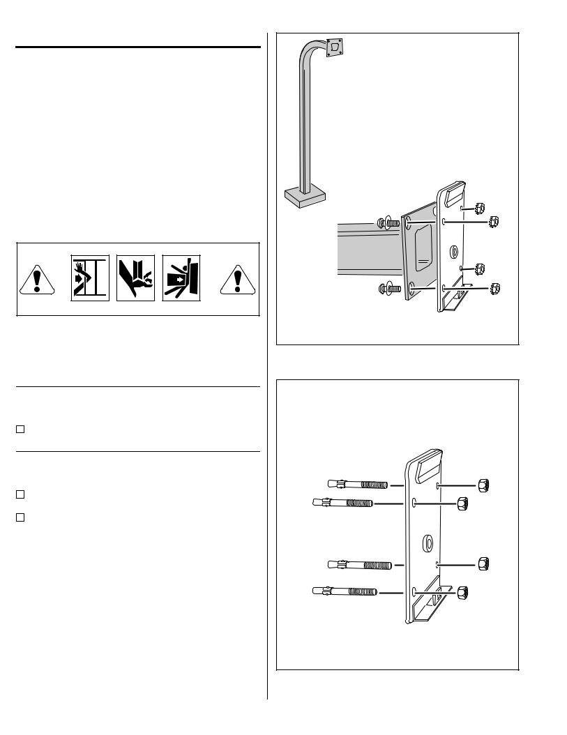
Pedestal Mounting
The AccessKey keypad can be mounted on a standard pedestal.
Use four security bolts and locking nuts to secure the keypad’s backplate to the pedestal (see Figure 3).
Wall Mounting
The AccessKey keypad can be mounted directly to a wall or flat surface.
Use the appropriate fasteners to secure the keypad’s backplate to the mounting surface.
When mounting the keypad to a concrete wall, use concrete wedge anchors or molly anchors (see Figure 4).
4
PEDESTAL |
MOUNT BACKPLATE WITH |
SECURITY BOLTS AND LOCKNUTS |
Figure 3. Pedestal Mounting Keypad Backplate
WALL MOUNTING
USE CONCRETE
WEDGE ANCHORS
OR MOLLY ANCHORS
Figure 4. Wall Mounting Keypad Backplate
 Loading...