


LRA
Linear Residential Actuator
Installation Guide
INTE
RT
E
K
CM
C US
L
I
S
TED
Operator models contained in this manual conform to UL325 standard for use in Class I, II, III, and IV applications
USA & Canada (800) 421-1587 & (800) 392-0123
(760) 438-7000 - Toll Free FAX (800) 468-1340
www.linearcorp.com
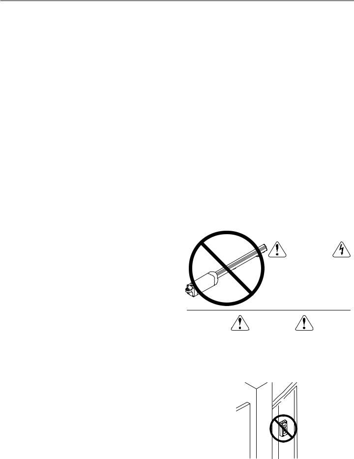
Table of Contents
Pre-installation Information. . . . . . . . . . . . . . . . . . . . . . . . . . . . . . . . . . |
|
.1 |
|
Operation Indications. . . |
. . . . . . . . . . . . . |
. |
. . . . . |
. . . . . . . . . . . . . . |
. |
. |
.21 |
|
||||||||
Before You Begin.... . . . . . . . . . . . . . . . . . . . . . . . . . . . . . . . . . . . . . . . |
|
.1 |
|
|
|
Power-up Display . . . . . . . . . . . . . . . . . . . . . . .. . |
. |
|
.21. . . . . . . . . |
|||||||||||
Always Check the Gate’s Action. . . . . . . . . . . . . . . . . . . . . . . . . . . . |
|
.1 |
|
|
|
Idle Condition |
. . . . . |
. . |
. . . . . . . . . . . . |
. |
. . . . . |
. . . . . . . . . . . . . . |
. |
. |
.21 |
|
||||
Gate Operator Classifications. . . . . . . . . . . . . . . . . . . . . . . . . . . . . . |
|
.1 |
|
|
|
Last Gate Position/Condition . . . . . . . . . . . . . . . . .. . |
. |
|
.21. . . . . . . . . |
|||||||||||
Approved Obstruction Detection Devices. . . . . . . . . . . . . . . . . . . . . |
|
.1 |
|
|
|
Pre-start Delay . . . . . . |
. . . . . . . . . . . . |
. |
. . . . . |
. . . . . . . . . . . . . . |
. |
. |
.21 |
|
||||||
Safety Information and Warnings . . . . . . . . . . . . . . . . . . |
|
|
|
|
|
Reverse Delay . . . . . . . . . . . . . . . . . . . . . . . .. . |
. |
|
. 21. . . . . . . . . |
|||||||||||
|
.1. . . . . . . . . . |
|
|
|
|
|
|
|
|
|
|
|
|
21 |
|
|||||
Regulatory Warnings . . . . . . . . . . . . . . . . . . . . . . . |
|
|
|
|
|
Run Timer |
. . |
|
. |
. . . . . |
. . |
. . . . . . . . . . . . |
. |
. . . . . |
. . . . . . . . . . . . . . |
. |
. |
|
||
|
1. . . . . . . . . . . . . |
|
|
|
|
|
|
|
|
|
|
|
|
|||||||
Linear Actuator Operator Overview . . . . . . . . . . . . . . . . . |
|
|
Error Indications. |
. . . . . |
. . |
. . . . . . . . . . . . |
. |
. . . . . |
. . . . . . . . . . . . . . |
. |
. |
.21 |
|
|||||||
2. . . . . . . . . . |
|
|
|
|
|
|
|
|
|
|
|
|
21 |
|
||||||
Wiring Specifications |
|
2 |
|
|
|
Entrapment |
. |
. |
. . . . . |
. . |
. . . . . . . . . . . . |
. |
. . . . . |
. . . . . . . . . . . . . . |
. |
. |
|
|||
|
|
|
|
COMM LINK Connection Failure . . . . . . . . . . . . . . . |
. |
|
.21. . . . . . . . . |
|||||||||||||
AC Power Wiring |
|
2 |
|
|
|
|
||||||||||||||
|
|
|
|
MGT Obstacle Transmitter Trouble |
|
|
21 |
|
||||||||||||
DC Control and Accessory Wiring . . . . . . . . . . . . . . . . |
|
|
|
|
|
. |
. |
|
||||||||||||
|
.2. . . . . . . . . |
|
|
|
|
|
|
|
|
|
|
. |
. |
21. . . . . . . . . . |
||||||
Control Box Mounting . . . . . . . . . . . . . . . . . . . . . . . . |
|
|
|
|
Maximum Run Time Exceeded . . . . . . . . . . . . . . .. . |
|||||||||||||||
.2. . . . . . . . . . . . . |
. . . . . . . . . . . . . . . . . . . . . . . . . |
. |
. |
22. . . . . . . . . . |
||||||||||||||||
Gate Layout Illustration |
|
3 |
|
Troubleshooting. |
. |
|||||||||||||||
|
|
|
|
Contacting Technical Support |
|
|
22 |
|
||||||||||||
Mounting Bracket Installation |
|
4 |
|
|
|
. |
. |
|
||||||||||||
. |
|
|
|
Operator fails to start . . . . . . . . . . . . . . . . . . . . .. . |
. |
|
.22. . . . . . . . . |
|||||||||||||
Post Bracket Installation . . . . . . . . . . . . . . . . . . . . . . . . . . . . . . . . . . |
. |
4 |
|
|
|
Motor operates, but gate does not move . . . . . . . . . . .. . |
. |
|
.22. . . . . . . |
|||||||||||
Gate Bracket Installation. . . . . . . . . . . . . . . . . . . . . . . |
|
4. . . |
. . . .Motor. . . sounds. . |
like it is working harder than normal . . . . .. . |
. |
. |
22. . . . . |
|||||||||||||
Operator Setup . . . . . . . . . . . . . . . . . . . . . . . . . . . . . . . . . . . . . . . . . . . . |
. |
5 |
|
|
|
Gate stopping part way open or closed (but no visible obstruction).22 |
||||||||||||||
Operator Mounting . . . . . . . . . . . . . . . . . . . . . . . . . . . . . . . . . . . . . . |
. |
5 |
|
|
|
Gate staying open with automatic system . . . . . . . . . .. . |
. |
. 22. . . . . . . |
||||||||||||
Controller Connection. . . . . . . . . . . . . . . . . . . . . . . . . . . . . . . . . . . . |
. |
5 |
|
|
|
How to Order Replacement Parts. . . . . . . . . . . . . . . . . . . . . . . . |
. |
. |
.22 |
|
||||||||||
AC Power Connection. . . . . . . . . . . . . . . . . . . . . . . . |
|
.5. . . Model. . . . LRA. . .Replacement. . |
Parts . . . . . . . . . . . . . . . . . . . . . . . . . . . . |
. |
. |
.23 |
|
|||||||||||||
Earth Ground. . . . . . . . . . . . . . . . . . . . . . . . . . . . . |
|
5. . . . . . . . . . . . . . . |
|
|
|
|
|
|
|
24 |
|
|||||||||
Limit Switch Adjustment |
|
6 |
|
Preventative Maintenance . . . . . . . . . . . . . . . . . . . . . . . . . . . . . . . . |
. |
. |
|
|||||||||||||
. |
|
|
|
General |
|
|
|
|
|
|
|
|
|
|
|
|
24 |
|
||
Manual Disconnect |
|
6 |
|
|
|
. |
. |
|
. |
. . . . . |
. . |
. . . . . . . . . . . . |
. |
. . . . . |
. . . . . . . . . . . . . . |
. |
. |
|
||
. |
|
|
|
Lubrication . . . . . . . . . . . . . . . . . . . . . . . . . .. . |
. |
|
. 24. . . . . . . . . |
|||||||||||||
Controller Features. . . . . . . . . . . . . . . . . . . . . . . . . . . |
. |
7. . . |
|
. . . 6. -Month. . . . Preventative. . . |
Maintenance. . . . . . . . . . . . . . . |
. |
. |
24. . . . . . . . . |
||||||||||||
Indicator Descriptions . . . . . . . . . . . . . . . . . . . . . . . . |
|
|
|
|
|
Battery Maintenance . . . . . . . . . . . . . . . . . . . . .. . |
. |
|
.24. . . . . . . . . |
|||||||||||
|
.8. . . . . . . . . . . . . |
|
|
|
|
|
|
|
|
|
|
|||||||||
Terminal Descriptions . . . . . . . . . . . . . . . . . . . . . . . . |
|
|
|
FCC Notice. . |
. |
. |
. |
. |
. . . . . . . . . . . . . . . . . . . . . . . . . . |
. |
|
. 24. . . . . . . . . |
||||||||
|
.9. . . . . . . . . . . |
|
|
|
|
|
|
|
|
|
|
|
|
|||||||
|
|
|
|
Gate Operator Installation Checklist . . . . . . . . . . . . . .. . |
. |
|
. 26. . . . . . . . . |
|||||||||||||
Operator Accessory Connections. . . . . . . . . . . . . . . . . . . 10. . . . . . . . . . |
|
|
|
|
|
|
|
|
|
|
|
|
|
|
||||||
Basic Controller Programming.. .. .. .. .. .. .. .. .. .. .. .. .. .. .. .. .. .. .. .. .. .. .. .. .. .. .. .. .. .. .. |
11 |
|
|
|
|
|
|
|
|
|
|
|
|
|
|
|
|
|
|
|
Programming Overview. . . . . . . . . . . . . . . . . . . . . . . |
11. . . . . . . . . . . . |
|
|
|
|
|
|
|
|
|
|
|
|
|
|
|||||
Entering Programming Mode . . . . . . . . . . . . . . . . . . . . . . . . . . . . . . |
11 |
|
|
|
|
|
|
|
|
|
|
|
|
|
|
|
|
|
|
|
Exiting Programming Mode. . . . . . . . . . . . . . . . . . . . . |
11. . . . . . . . . . . |
|
|
|
|
|
|
|
|
|
|
|
|
|
|
|||||
Programming Keystrokes . . . . . . . . . . . . . . . . . . . . . . . . . . . . . . . . . |
11 |
|
|
|
|
|
|
|
|
|
|
|
|
|
|
|
|
|
|
|
Left or Right Hand Operation.. .. .. .. .. .. .. .. .. .. .. .. .. .. .. .. .. .. .. .. .. .. .. .. .. .. .. .. .. .. |
11 |
|
|
|
|
|
|
|
|
|
|
|
|
|
|
|
|
|
|
|
Dual Gate Enable . . . . . . . . . . . . . . . . . . . . . . . . . . . . . . . . . . . . . . . |
11 |
|
|
|
|
|
|
|
|
|
|
|
|
|
|
|
|
|
|
|
Auto Close Timer. . . . . . . . . . . . . . . . . . . . . . . . . . . |
11. . . . . . . . . . . . . |
|
|
|
|
|
|
|
|
|
|
|
|
|||||||
Run Alarm and Pre-start Alarm. . . . . . . . . . . . . . . . . . . |
12. . . . . . . . . . |
|
|
|
|
|
|
|
|
|
|
|
|
|
|
|||||
Maximum Open Direction Current Setting. . . . . . . . . . . . . . 12. . . . . . . |
|
|
|
|
|
|
|
|
|
|
|
|
|
|
||||||
Maximum Close Direction Current Setting . . . . . . . . . . . . . . . . . . . . |
12 |
|
|
|
|
|
|
|
|
|
|
|
|
|
|
|
|
|
|
|
Advanced Controller Programming. . . . . . . . . . . . . . . . . . . |
13. . . . |
|
. . . . . |
|
|
|
|
|
|
|
|
|
|
|
|
|
|
|||
Entering Advanced Programming Mode. . . . . . . . . . . . . . . . . . . . . . |
13 |
|
|
|
|
|
|
|
|
|
|
|
|
|
|
|
|
|
|
|
Maximum Run Time . . . . . . . . . . . . . . . . . . . . . . . . . . . . . . . . . . . . . |
13 |
|
|
|
|
|
|
|
|
|
|
|
|
WARNING |
|
|
|
|
||
Single Button Input Setup. . . . . . . . . . . . . . . . . . . . . . . . . . . . . . . . . |
13 |
|
|
|
|
|
|
|
|
|
|
|
|
|
|
|
|
|||
Stagger Mode. . . . . . . . . . . . . . . . . . . . . . . . . . . . . . . . . . . . . . . . . . |
13 |
|
|
|
|
|
|
|
|
|
|
|
|
|
|
|
|
|
|
|
Stagger Delay Time. . . . . . . . . . . . . . . . . . . . . . . . . |
13. . . . |
. |
. . . . . . . . |
|
|
|
|
|
ONLY QUALIFIED |
|
|
|
|
|||||||
Auxiliary Relay Mode . . . . . . . . . . . . . . . . . . . . . . . |
14. . . . |
|
. . . . . . . . |
|
|
|
|
|
|
|
|
|
|
|||||||
|
|
|
|
|
|
|
|
|
SHOULD WORK ON |
|
|
|
|
|||||||
Reverse Delay Time |
14 |
|
|
|
|
|
|
|
|
|
|
|
|
|
|
|
|
|||
|
|
|
|
|
|
|
|
|
|
|
LINEAR RESIDENTIAL |
|
|
|
|
|||||
Low Power Mode . . . . . . . . . . . . . . . . . . . . . . . . . |
14. . . . |
|
. . . . . . . . . |
|
|
|
|
|
|
|
|
|
||||||||
|
|
|
|
|
|
|
ACTUATORS |
|
|
|
|
|||||||||
Power Failure Mode. . . . . . . . . . . . . . . . . . . . . . . . . |
14. . . . |
|
. |
. . . . . . . . |
|
|
|
|
|
|
|
|
|
|
|
|||||
Soft Start/Stop Duration . . . . . . . . . . . . . . . . . . . . . . . . . . . . . . . . . . |
15 |
|
|
|
|
|
|
|
|
|
|
|
|
|
|
|
|
|
|
|
Reset Cycle Count . . . . . . . . . . . . . . . . . . . . . . . . . . . . . . . . . . . . . . |
15 |
|
|
|
|
|
|
|
|
|
|
|
|
|
|
|
|
|
|
|
Maintenance Alert Trigger. . . . . . . . . . . . . . . . . . . . . . |
15. . . . |
|
. . . . . . . |
|
|
|
|
|
|
|
|
|
|
|
|
|
|
|||
Mid-travel Stop Position. . . . . . . . . . . . . . . . . . . . . . . |
15. . . . |
. |
. . . . . . . |
|
|
|
|
|
|
|
|
|
|
|
|
|
|
|||
. .Motor Type Selection . . . . . . . . . . . . . . . . . . . . . . . |
15. . . . |
|
. |
. . . . . . . |
|
|
|
|
|
|
|
|
|
|
|
|
|
|
||
Radio Enable. . . . . . . . . . . . . . . . . . . . . . . . . . . . . |
16. . . . |
|
. . . . . . . . . . |
|
|
WARNING |
|
|
|
|
||||||||||
Antenna Installation. . . . . . . . . . . . . . . . . . . . . . . . . |
16. . . . |
|
. |
. . . . . . . . |
|
|
|
|
|
|
|
|
|
|||||||
Radio Transmitter Learn . . . . . . . . . . . . . . . . . . . . . . . . . . . . . . . . . . |
16 |
|
|
|
|
|
|
|
|
|
|
|
|
|
|
|
|
|
|
|
Radio Transmitter Delete. . . . . . . . . . . . . . . . . . . . . . . |
16. . . . |
|
. . . . . . . |
|
|
|
|
|
|
|
|
|
|
BE |
|
|||||
MGT Obstacle Transmitter Learn |
16 |
|
|
CONTROLS INTENDED FOR USER ACTIVATION MUST |
|
|||||||||||||||
|
|
LOCATED AT LEAST SIX FEET (6') AWAY FROM ANY MOVING |
|
|||||||||||||||||
MGT Obstacle Transmitter Delete . . . . . . . . . . . . . . . . |
16. . . . |
|
|
|||||||||||||||||
|
. . . . . |
|
|
|
|
|
|
|
|
|
|
|
|
|
|
|||||
Reset Controller to Factory Defaults. . . . . . . . . . . . . . . . . |
16. . . |
. |
|
.PART. . . OF THE GATE AND WHERE THE USER IS PREVENTED |
|
|||||||||||||||
Loop Layout Illustration. . . . . . . . . . . . . . . . . . . . . . . . . . . . . . . . . . . . . |
17 |
|
|
FROM REACHING OVER, UNDER, AROUND OR THROUGH THE |
|
|||||||||||||||
Safety Edge Layout Illustration. . . . . . . . . . . . . . . . . . . . . . . . . . . . . . . |
18 |
|
|
GATE TO OPERATE THE CONTROLS. OUTDOOR OR EASILY |
|
|||||||||||||||
Photoeye Installation Illustration . . . . . . . . . . . . . . . . . . |
19. . . . |
|
ACCESSIBLE CONTROLS SHALL HAVE A SECURITY FEATURE |
|
||||||||||||||||
|
. . . . . . |
|
|
|
|
|
|
|
|
|
|
|
|
|
|
|||||
Dual Gate Installations |
20 |
|
|
TO PREVENT UNAUTHORIZED USE. |
|
|
|
|
||||||||||||
|
|
|
|
|
|
|
|
|
|
|
|
|
|
|
|
|
|
|||
Gate Operation . . . . . . . . . . . . . . . . . . . . . . . . . . . . |
20. . . . |
|
. . . . . . . . . . . |
|
|
|
|
|
|
|
|
|
||||||||
|
|
|
|
|
|
|
|
|
||||||||||||
Open Button . . . . . . . . . . . . . . . . . . . . . . . . . . . . . . . . . . . . . . . . . . . |
20 |
|
|
|
|
|
|
|
|
|
|
|
|
|
|
|
|
|
|
|
Close Button. . . . . . . . . . . . . . . . . . . . . . . . . . . . . . . . . . . . . . . . . . . |
20 |
|
|
|
|
|
|
|
|
|
|
|
|
|
|
|
|
|
|
|
. . . . . . . . . . . . . . . . . . . . . . . . . . . . . . . . . . . . . . . . . . . .Stop Button |
20 |
|
|
|
|
|
|
|
|
|
|
|
|
|
|
|
|
|
|
|
|
|
|
|
|
|
|
|
|
|
|
|
|
|
|
|
|
|
|||
. .Single Input . . . . . . . . . . . . . . . . . . . . . . . . . . . |
20. . . . |
. |
. . . . . . . . . . |
|
|
|
|
|
|
|
|
|
||||||||
Fire Department Input. . . . . . . . . . . . . . . . . . . . . . . . |
20. . . . |
|
. . . . . . . . |
|
|
|
|
|
|
|
|
|
|
|
|
|
|
|||
Open Input. . . . . . . . . . . . . . . . . . . . . . . . . . . . . . |
20. . . . |
|
. . . . . . . . . . . |
|
|
|
|
|
|
|
|
|
||||||||
Open Obstruction . . . . . . . . . . . . . . . . . . . . . . . . . . . . . . . . . . . . . . . |
20 |
|
|
|
|
|
|
|
|
|
|
|
|
|
|
|
|
|
|
|
Close Obstruction. . . . . . . . . . . . . . . . . . . . . . . . . . . . . . . . . . . . . . . |
20 |
|
|
|
|
|
|
|
|
|
|
|
|
|
|
|
|
|
|
|
Reverse Input . . . . . . . . . . . . . . . . . . . . . . . . . . . . . . . . . . . . . . . . . . |
20 |
|
|
|
|
|
|
|
|
|
|
|
|
|
|
|
|
|
|
|
Open Loop. . . . . . . . . . . . . . . . . . . . . . . . . . . . . . |
20. . . . |
|
. . . . . . . . . . . |
|
|
|
|
|
|
|
|
|
||||||||
Reverse Loop . . . . . . . . . . . . . . . . . . . . . . . . . . . . . . . . . . . . . . . . . . |
20 |
|
|
|
|
|
|
|
|
|
|
|
|
|
|
|
|
|
|
|
Shadow/Reset Loop . . . . . . . . . . . . . . . . . . . . . . . . . . . . . . . . . . . . . |
20 |
|
|
|
|
|
|
|
|
|
|
|
|
|
|
|
|
|
|
|
|
|
|
|
|
|
|
|
|
|
|
|
|
|
|
|
|
|
|||
|
|
|
|
|
|
|
|
|
|
|
|
|
|
|
||||||
LRA Linear Residential Actuator Installation Guide |
|
- 2 - |
|
|
|
|
|
|
|
|
|
228158 Revision X13 2-3-2009 |
||||||||
Pre-installation Information |
|
|
Safety Information and Warnings |
|
|
||||
Before You Begin... |
|
|
THE FOLLOWING FORMATS ARE USED FOR SAFETY NOTES |
||||||
|
|
|
|
IN THESE INSTRUCTIONS. |
|
|
|||
Before unpacking, inspect the carton for exterior damage.. If |
|
|
|
|
|||||
|
|
|
|
|
|||||
|
|
CAUTION |
|
|
|||||
you find damage, advise the delivery carrier of a potential |
|
|
|
|
|||||
claim.. Inspect your package carefully.. You can check your |
|
|
This type of warning note is used to |
|
|||||
accessory box parts with the enclosed packing slip for your |
|
|
indicate the possibility of damage to the |
|
|||||
convenience.. Claims for shortages will be honored for only |
|
|
gate or gate operator. |
|
|
||||
30 days from the date of shipment.. |
|
|
|
|
|
|
|
||
|
|
|
|
WARNING |
|
|
|||
Before installing the operator, read this manual completely to |
|
|
|
|
|||||
|
|
This type of warning note is used to |
|
||||||
ensure all requirements for proper installation are present..Verify |
|
|
|
||||||
|
|
indicate possible mechanical hazards that |
|
||||||
that the voltage to be used matches the voltage of the operator.. |
|
|
|
||||||
|
|
may cause serious injuries or |
|
|
|||||
If you have any questions about the requirements for proper |
|
|
|
|
|||||
|
|
|
|
|
|||||
installation of this gate operator contact technical support at |
|
|
WARNING |
|
|
||||
|
|
|
|
|
|||||
800-421-1587.. |
|
|
|
|
|
|
|
||
|
|
|
|
This type of warning note is used to indicate |
|
||||
|
|
|
|
|
|
|
|||
Always Check the Gate’s Action |
|
|
|
|
possible electrical shock hazards that may |
|
|||
It’s very important before installing the gate operator to |
|
|
cause serious injuries or death. |
|
|
||||
Regulatory Warnings |
|
|
|||||||
make sure the gate’s swing is free and level throughout |
|
|
|||||||
the entire swing path. If the gate does not seem to |
Read the following before beginning to |
install Linear’s |
|||||||
operate properly, it may affect the operator performance |
Residential Actuators: |
|
|
||||||
or greatly shorten the life of the unit. The gate should |
|
|
|
|
|
||||
IMPORTANT INSTALLATION SAFETY INSTRUCTIONS |
|||||||||
also be designed so that airflow is ample to prevent |
|||||||||
wind resistance and drag. |
|
|
|
|
WARNING |
|
|
||
|
|
|
|
|
|
|
|||
Gate Operator Classifications |
|
|
|
|
|
|
|
||
|
|
TO REDUCE THE RISK OF SEVERE INJURY OR DEATH |
|||||||
All gate operators can be divided into one of four different |
|||||||||
TO PERSONS, REVIEW THESE INSTALLATION SAFETY |
|||||||||
classifications, depending on their design and usage.. Install |
|||||||||
this gate operator only when the operator is appropriate for |
|
|
STEPS BEFORE PROCEEDING |
||||||
|
|
|
|
|
|||||
the construction and usage class as defined below: |
|
|
1. |
READ AND FOLLOW ALL INSTALLATION INSTRUCTIONS. |
|||||
• Class I Residential Vehicular Gate Operator |
|
|
|||||||
|
|
2. |
Read the yellow “Safety Instructions” brochure enclosed with the |
||||||
|
A vehicular gate operator intended for use in a home or for one to |
||||||||
|
|
packet of information. If any pages are missing or are unreadable, |
|||||||
|
four single family dwellings with a common garage or parking area |
|
|||||||
|
|
or you do not have the safety instructions, please call Linear at |
|||||||
|
associated with these dwellings. |
|
|
|
1 800 421-1587 to request additional copies. |
|
|
||
• Class II Commercial / General Access Vehicular Gate Operator |
|
|
3. |
ALL ELECTRICAL CONNECTIONS TO THE POWER SUPPLY MUST |
|||||
|
A vehicular gate operator intended for use in a commercial location or |
|
BE MADE BY A LICENSED ELECTRICIAN AND MUST OBSERVE ALL |
||||||
|
|
NATIONAL AND LOCAL ELECTRICAL CODES. |
|
|
|||||
|
building such as a multi-family housing unit of five or more single family |
|
|
|
|||||
|
4. |
A separate power-disconnect switch should be located near the |
|||||||
|
units, hotel, retail store or other building servicing the general public. |
|
|
||||||
|
|
|
|
operator so that primary power can be turned off when necessary. |
|||||
• Class III Industrial / Limited Access Vehicular Gate Operator |
|
|
|
||||||
|
|
5. |
Install the enclosed warning signs on both sides of the gate. A |
||||||
|
A vehicular gate operator intended for use in an industrial location or |
|
minimum of two (2) WARNING SIGNS shall be installed, one on each |
||||||
|
building such as a factory or loading dock area or other location not |
|
side of the gate where easily visible. |
|
|
||||
|
intended to service the general public. |
|
|
6. |
Never reach between, through or around the fence to operate the |
||||
• Class IV Restricted Access Vehicular Gate Operator |
|
|
|
gate. |
|
|
|||
|
|
7. |
Never connect a button station within reach of the gate or on the |
||||||
|
A vehicular gate operator intended for use in a guarded industrial |
||||||||
|
|
side of the gate operator. |
|
|
|||||
|
location or building such as an airport security area or other restricted |
|
|
|
|||||
|
8. |
Do not adjust the operator controller’s current sensing feature too |
|||||||
|
access locations not servicing the general public, in which unauthorized |
||||||||
|
|
high. It should be adjusted high enough to keep the gate from falsely |
|||||||
|
access is prevented via supervision by security personnel. |
|
|
|
|||||
|
|
|
|
triggering the sensing, but no higher than necessary for the gate to |
|||||
Approved Obstruction Detection Devices |
|
|
|
operate. DO NOT DEFEAT THE PURPOSE OF THIS FUNCTION! |
|||||
|
|
9. |
You must install all required safety equipment. |
|
|
||||
The following contact or non-contact obstruction detection |
|
|
|||||||
10. |
UL325 Compliance requires the use of contact edges or photoelectric |
||||||||
devices have been approved for use with Linear’s Residential |
|
controls on all automatic or remotely-controlled gate operators. |
|||||||
Actuators as part of a UL325 compliant installation: |
|
|
11. |
The operator is intended for installation only on gates used for |
|||||
• |
Contact Edges |
|
|
|
vehicles. Pedestrians must be supplied with a |
separate access |
|||
|
|
|
opening. The pedestrian access opening shall |
be designed to |
|||||
|
Miller Edge Models MGO20, MGR20, MGS20, ME120 |
|
|
|
|||||
|
|
|
|
promote pedestrian usage. Locate the gate such that persons will |
|||||
• |
Photoeyes |
|
|
|
|||||
|
|
|
not come into contact with the vehicular gate during the entire path |
||||||
|
MMTC Model IR-55 (165’ range - P/N 2520-441) |
|
|
|
of travel of the vehicular gate. |
|
|
||
|
MMTC Model E3K (28’ range - P/N 2520-031) |
|
|
|
|
|
|
|
|
|
|
|
|
|
|||||
LRA Linear Residential Actuator Installation Guide |
- 1 - |
|
|
228158 Revision X13 2-3-2009 |
|||||
Linear Actuator Operator Overview
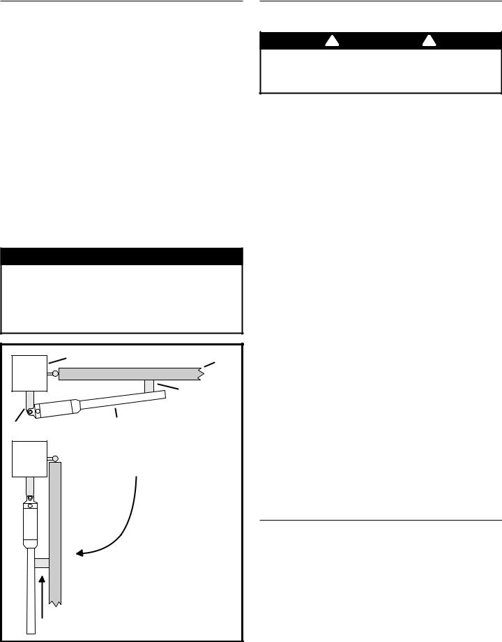
The Model LRA Residential Linear Actuator is designed to open and close a light-duty residential swing gate.. The operator can be used in left hand or right hand swing gate installations on gates weighing up to 600 pounds..
The operator is connected by a cable to an APeX electronic controller, which provides all connections for input and entrapment detection devices.. The Controller is housed in a separate enclosure and contains a built-in radio receiver for wireless activation by remote control transmitters..
Brackets attached to the gate and gate hinge post are for mounting the operator and to provide a mechanism to move the gate..
When the operator activates, the worm drive in the linear actuator changes the fixed distance between the two brackets that the operator is mounted on..When the operator pulls the two brackets closer together, the gate opens..When the operator pushes the two brackets farther apart, the gate closes (see Figure 1)..
Adjustable magnetic limit switches in the operator detect the open and closed positions of the gate..
 WARNING
This operator is intended for installation only on gates used for vehicles. Pedestrians must be supplied with a separate access opening. The pedestrian access opening shall be designed to promote pedestrian usage. Locate the gate such that persons will not come into contact with the vehicular gate during the entire path of travel of the vehicular gate.
GATE POST |
GATE CLOSED |
GATE |
|
|
|
|
|
GATE BRACKET |
POST BRACKET |
ACTUATOR |
|
|
|
GATE OPEN
THE ACTUATOR PULLS THE
GATE BRACKET TOWARDS THE POST
BRACKET TO OPEN THE GATE
Figure 1. Linear Actuator Operation
Wiring Specifications
Refer to the following steps for details on power and accessory the operator..
 WARNING
ALL AC ELECTRICAL CONNECTIONS TO THE POWER SOURCE AND THE OPERATOR MUST BE MADE BY A LICENSED ELECTRICIAN AND MUST OBSERVE ALL NATIONAL AND LOCAL ELECTRICAL CODES
USE COPPER WIRE ONLY!
AC Power Wiring
|
MODEL LRA POWER WIRING |
|
||
SUPPLY VOLTS |
MAXIMUM DISTANCE (FEET) |
WIRE GAUGE |
||
SINGLE |
DUAL |
|||
|
|
|||
115 VOLTS |
3288 |
1644 |
14 |
|
5224 |
2612 |
12 |
||
|
||||
1.The distance shown in the table above is measured in feet from the operator to the power source. DO NOT EXCEED THE MAXIMUM DISTANCE. These calculations have been based on a standard 115 V supply with a 10% drop allowable. If your supply is under the standard rating, the runs listed may be longer than what your application will handle, and you should not run wire too near the maximum distance for the gauge of wire you are using.
2.When large-gauge wire is used, a separate junction box (not supplied) may be needed for the operator power connection.
3.Wire length calculations are based on the National Electrical Code, Article 430 and have been carefully determined based on motor inrush and operator requirements.
4.Connect power in accordance with local codes. The green ground wire must be properly connected.
5.Wire insulation must be suitable to the application.
DC Control and Accessory Wiring
1.All control devices are now 24 VDC, which can be run up to 2000 feet with 14 AWG wire.
2.Control wiring must be run in a separate conduit from power wiring. Running them together may cause interference and faulty signals in some accessories.
3.A three-wire shielded conductor cable is required to connect two operators together for dual operation. You must use Belden 8760 Twisted Pair Shielded Cable (or equivalent) only – P/N 2500-1982, per foot). See Page 20 for details of this connection. Note:The shield wire should be connected in both the Controllers.
Control Box Mounting
Locate the control box in the vicinity of the operator.. The APeX Controller mounts inside the control box..The operator connects to the Controller via a 6 foot cable..
Mount the control box firmly to a non-movable object.. Knockouts are provided for conduits.. Do not mount the control box where a lawn sprinkler may spray water on it..
NOTE: When installing the cable connecting the operator to the control box, be sure to leave some slack to allow for the swing of the gate. Water tight connectors are highly recommended.
LRA Linear Residential Actuator Installation Guide |
- 2 - |
228158 Revision X13 2-3-2009 |
|
36" |
POST OR |
ENTRY |
|
|
PILLAR |
|
||
|
GATE HINGE |
|
||
|
RECOMMENDED |
|
|
GATE FULLY CLOSED |
|
|
|
|
|
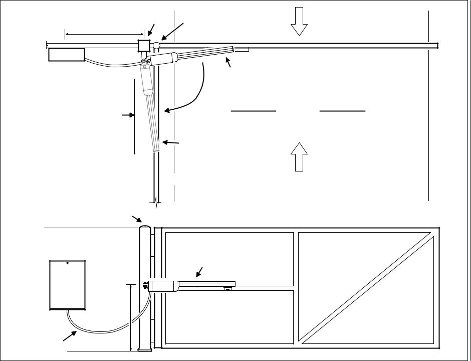
Installation ActuatorResidentialLinearLRA |
|
|
GATE TOP VIEW |
IllustrationLayoutGate |
CONTROL |
|
LRA ACTUATOR IN |
||
BOX |
|
|||
|
CLOSED POSITION |
|||
|
|
|||
MINIMUM BACKSPACE |
|
ROADWAY |
||
Guide |
|
|
||
8" FROM CENTER OF |
|
|
||
|
|
|
||
GATE HINGE |
|
|
|
|
|
|
|
|
|
|
|
|
LRA ACTUATOR IN |
|
|
LEFT HAND |
|
OPEN POSITION |
|
|
|
EXIT |
|
|
|
GATE OPERATION |
|
|
|
|
|
|
|
|
3 - |
SHOWN |
GATE FULLY OPEN |
|
|
- |
|
|
|
|
|
POST OR |
|
|
|
|
PILLAR |
|
GATE BACK SIDE VIEW |
|
|
CONTROL |
|
|
|
|
BOX |
|
LRA ACTUATOR |
|
|
|
|
|
|
228158 |
1/2 GATE |
|
|
|
HEIGHT |
|
|
|
|
Revision |
|
|
|
|
LEAVE SLACK |
|
|
|
|
|
|
|
|
|
X13 |
IN CABLE TO |
|
|
|
3-2 |
ALLOW FOR |
|
|
|
- |
GATE SWING |
|
|
|
2009 |
|
|
|
|
|
|
|
|
|
Mounting Bracket Installation
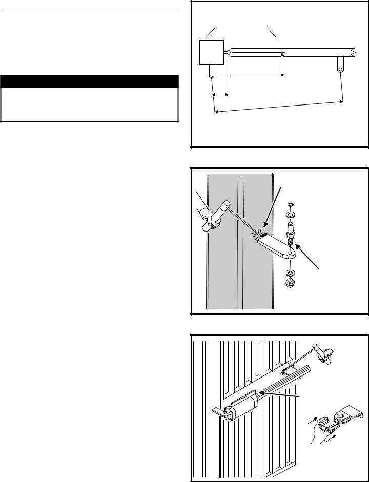
Examine Figure 2 for details of the required mounting locations for the two brackets.. The brackets must be mounted at the correct locations to allow the operator to open the gate at a 90 degree angle and to ensure the operator functions smoothly..
The brackets must also be mounted level in respect to each other so the operator’s front and rear mounting points are vertical and not offset at an angle..
 WARNING
The gate must be installed in a location so that enough clearance is supplied between the gate and adjacent structures when opening and closing to reduce the risk of entrapment. Swing gates shall not open into public areas.
1.Measure approximately halfway up the gate height and determine good strong spots located in the required areas to mount the brackets on the post and gate.
2.Using Figure 2 as a guide, mark the locations on the post or pillar and the gate for the two mounting brackets.
NOTE: Depending on the gate design, an additional reinforcing plate welded to the gate may be required to provide a good spot to mount the gate bracket.
Post Bracket Installation
NOTE: When installing the post bracket on a round post or masonry pillar, use improvised methods (additional plate with lag bolts and anchors, concrete wedge anchors, U-bolts, etc.) to securely fasten the bracket.
For square gate posts:
1.Tack weld the post bracket to the post at the marked spot and double check its level and height.
2.Finish welding the post bracket to the gate post.
3.After the welding is completed and the post bracket has cooled, install the post bracket pin as shown in Figure 3.
Gate Bracket Installation
Before welding the gate bracket, be sure the centers of the operator mounting holes on the brackets will end up 29-1/2” apart when the gate is fully closed..
1.Tack weld the gate bracket to the gate at the marked spot and double check its level and height.
2.Finish welding the gate bracket to the gate.
3.After the welding is completed and the gate bracket has cooled, snap the limit switch magnet assembly onto the gate bracket (see Figure 4).
4.From the top side of the gate bracket, slide the load bushing into the bracket hole.
Alternate method to locate the gate bracket:
1.Hold the gate bracket with the magnets installed onto the LRA traveler.
2.Run the unit to the full open position.
3.Place the rear of the arm onto the post bracket.
4.Manually fully open the gate.
5.Position the gate bracket in the required position.
6.Remove the magnet assembly and bolt or weld the bracket in place.
LOCATE POST BRACKET AT THESE |
NOTE: THE 5-1/2" AND |
|
DIMENSIONS FROM THE GATE |
||
6" DIMENSIONS ARE |
||
CENTERLINE AND HINGE POINT |
||
CRITICAL FOR PROPER |
||
|
||
|
GATE OPERATION |
6"
5-1/2" |
29-1/2"
SETTING THE BRACKETS AT THIS
DISTANCE WILL CAUSE THE GATE
TO OPEN AT 90 DEGREES (DEPENDING
ON THE LIMIT SWITCH SETTINGS)
Figure 2. Required Bracket Locations
WELD POST BRACKET
TO POST
ASSEMBLE POST
BRACKET PIN
Figure 3. Post Bracket Installation
WELD GATE |
BRACKET |
TO GATE |
USE A |
LEVEL |
SNAP MAGNET |
ASSEMBLY ONTO |
GATE BRACKET |
AFTER WELDING |
Figure 4. Gate Bracket Installation
LRA Linear Residential Actuator Installation Guide |
- 4 - |
228158 Revision X13 2-3-2009 |
Operator Setup
Operator Mounting
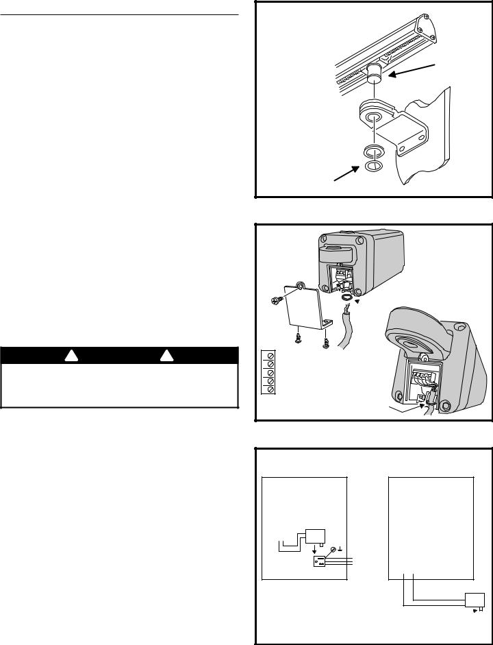
The operator mounts on the post bracket pin and into the gate bracket bushing.. Refer to Figure 5..
1.With the gate closed, carefully position the operator over the mounting brackets.
2.Lower the operator onto the post bracket pin while guiding the operator’s worm drive traveler shaft into the gate bracket bushing.
3.Install the washer and clip-ring on the post bracket pin.
4.Install the washer and clip-ring on the traveler shaft.
Controller Connection
The Controller is mounted in a locked enclosure.. Open the cover for installation access.. The operator’s interface cable plugs into the Controller and connects to the operator’s 5 position terminal block..
1.Remove the operator’s wiring access plate (see Figure 6).
2.Connect the interface cable to Terminals 1-5 on the Controller (see wire colors and terminal numbers in Figure 6).
3.Route the interface cable through a wiring knockout in the control box and towards the operator. Be sure to leave enough slack in the interface cable to allow for the gate swing.
4.Slide the O-ring over the end of the interface cable.
5.Connect the interface cable to the operator’s terminal block matching the same colors and terminal numbers used in Step 2 (see Figure 6).
6.Replace the operator’s wiring access plate being careful to align the O-ring below the cable clamp. The O-ring helps keep out moisture.
AC Power Connection
 WARNING
ALL AC ELECTRICAL CONNECTIONS TO THE POWER SOURCE AND THE OPERATOR MUST BE MADE BY A LICENSED ELECTRICIAN AND MUST OBSERVE ALL NATIONAL AND LOCAL ELECTRICAL CODES.
The control box contains a power disconnect switch to turn on and off the power available to the operator.. Following wiring specifications on Page 2, incoming power should be brought into the control box and connected to the labeled pigtails from the disconnect box.. A wiring connections print can be found on the label inside the cover of the operator.. See Figure 7 for power option examples..
Earth Ground
Install a ground rod and connect it to the control box in every installation.. A good earth ground is necessary to allow the Controller’s built in surge and lightning protection circuitry to work effectively..
NOTE: Do not splice the ground wire. Use a single piece of solid copper 12 AWG wire between the ground rod and the control box.
1.Install an 8-foot long copper ground rod within three feet of the control box.
2.Use a clamp to connect a solid copper 12 AWG ground wire to the ground rod.
3.Route the ground wire to the control box through a wiring knockout.
4.Connect the ground wire to the control box.
TRAVELER
SHAFT
GATE BRACKET 
BUSHING
WASHER
AND CLIP-RING
Figure 5. Mounting the Operator
PUT O-RING ON CABLE TO
 SEAL OUT MOISTURE
5 |
5 - OPEN LIMIT |
|
|
4 |
4 - COMMON (LIMIT) |
|
|
3 |
3 - CLOSE LIMIT |
|
|
2 |
2 - MOTOR |
|
|
1 |
1 - MOTOR |
|
|
MATCH TERMINAL NUMBERS |
O-RING |
||
FITS |
|||
ON OPERATOR & CONTROLLER |
|||
IN SLOT |
|||
|
Figure 6. Interface Cable Connection |
||
|
POWER OPTION #1 |
POWER OPTION #2 |
|
(BRING 115V INTO CONTROL BOX) |
(REMOTE LOCATED POWER SUPPLY) |
||
CONTROL BOX
TERMINAL STRIP
CONNECTION
24 VOLTS AC/DC
- +
GROUND
NEUTRAL
115V POWER HOT RECEPTACLE
BRING 115V HOT, NEUTRAL, AND GROUND INTO CONTROL BOX AND CONNECT TO POWER RECEPTACLE
PLUG TRANSFORMER INTO THE AC RECEPTACLE, TRANSFORMER OUTPUT CONNECTS TO THE TERMINAL STRIP
CONTROL BOX
TERMINAL STRIP
CONNECTION
24 VOLTS AC/DC
- +
PLUG-IN MAXIMUM DISTANCE TRANSFORMER 500 FT. 12 GA. WIRE
CONNECT TRANSFORMER  TO 115 VAC POWER SOURCE
IF BEYOND 500 FT. USE BRIDGE RECTIFIER TO CONVERT 24 VAC TO 24 VDC AT PLUG-IN TRANSFORMER LOCATION
Figure 7. Power and Ground Connections
LRA Linear Residential Actuator Installation Guide |
- 5 - |
228158 Revision X13 2-3-2009 |
Operator Setup (Continued)
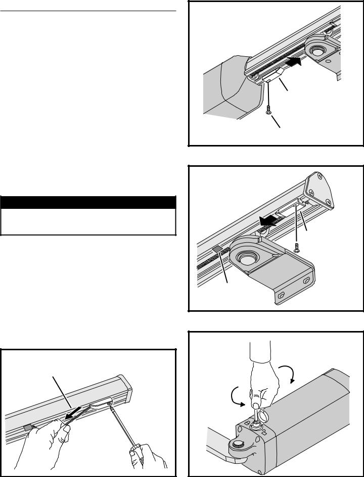
Limit Switch Adjustment
The open and close limit switches are adjustable by sliding them on the operator’s frame.. Sliding either switch closer to the center of the operator decreases the gate travel..
1.To limit the opening travel of the gate for setup, loosen the locking screw on the open limit switch, slide the switch towards the center of the operator (see Figure 8).
2.With the gate closed, apply power to the Controller, STAY CLEAR OF THE GATE and press the OPEN button.
3.Observe the gate as it opens, and watch the point where it stops.
4.To limit the closing travel of the gate for setup, loosen the locking screw on the close limit switch, remove the wire holding plugs from the wire slot in the channel, slide the switch towards the center of the operator (see Figure 9).
5.Be sure to STAY CLEAR OF THE GATE and press the CLOSE button.
6.Observe the gate as it closes, and watch the point where it stops.
7.Adjust the two limit switches until the open and close stopping points are set correctly for the gate. TIGHTEN THE LOCKING SCREWS ON THE LIMIT SWITCHES.
 CAUTION
Be careful not to damage the limit switch wires while adjusting the limit switches. Gently pull the limit switch wire while tightening the limit switch locking screw (see Figure 10).
8.Push any extra limit wire back into the motor housing. Replace the limit switch wire holding plugs to retain the limit switch wire.
Manual Disconnect
In case of a power failure or other condition, the gate can be manually moved without action from the operator by using the manual disconnect switch (see Figure 11).
To activate the manual disconnect switch:
1.Open the cover on the switch.
2.Insert the disconnect key (supplied with operator).
3.Turn the key clockwise 90˚.
4.Reverse the steps to re-engage the operator.
AVOID PINCHING THE LIMIT SWITCH
WIRE BY GENTLY PULLING IT WHILE
TIGHTENING THE LIMIT SWITCH
Figure 10. Limit Switch Wire
SLIDE OPEN LIMIT SWITCH |
TO ADJUST OPEN LIMIT |
OPEN LIMIT SWITCH |
LIMIT SWITCH LOCKING SCREW |
Figure 8. Open Limit Switch
SLIDE CLOSE LIMIT SWITCH
TO ADJUST CLOSE LIMIT
CLOSE LIMIT SWITCH
 LIMIT SWITCH
LOCKING SCREW
REMOVE AND REPLACE
LIMIT WIRE PLUG DURING
LIMIT SWITCH ADJUSTMENT
Figure 9. Close Limit Switch
MANUAL DISCONNECT |
|
|
CAN BE USED TO |
|
|
DISENGAGE |
DISCONNECT |
|
OPERATOR |
||
(UNLOCK) |
||
|
||
CONNECT |
|
|
(LOCK) |
|
Figure 11. Manual Disconnect
LRA Linear Residential Actuator Installation Guide |
- 6 - |
228158 Revision X13 2-3-2009 |

Controller Features
WHIP
ANTENNA
POWER
INDICATORS
DISPLAY
PROGRAMMING
BUTTONS
INPUT
POWER
TERMINALS
ACCESSORY
POWER
TERMINALS
RESET
BUTTON
TERMINALS
PRIMARY/
SECONDARY
COMM LINK
TERMINALS
SINGLE
INPUT
TERMINALS
FIRE DEPT
INPUT
TERMINALS
OPEN INPUT
TERMINALS
OPERATION AND
OPERATION PROGRAMMING BUTTONS INDICATORS
3-BUTTON |
|
STATION |
SHADOW/RESET |
TERMINALS |
|
OPEN AND CLOSE |
|
REVERSE LOOP |
LIMIT SWITCH |
AUXILIARY |
|
|
RELAY |
||||
OBSTRUCTION |
REVERSE |
INPUT TERMINALS |
INPUT TERMINALS |
TERMINALS |
|
INPUT TERMINALS |
|||||
INPUT |
|
|
|
||
|
|
|
|
||
|
TERMINALS |
|
|
ALARM |
|
|
OPEN LOOP |
SHADOW/RESET LOOP |
|||
|
INPUT TERMINALS |
|
INPUT TERMINALS |
OUTPUT |
|
|
|
|
|
TERMINALS |
|
ANTENNA
CONNECTOR
SOLAR
PANEL
TERMINALS
MOTOR
BOARD
COVER
BATTERY
TERMINALS
PLUG-IN
LOOP
DETECTOR
CONNECTORS
AC MOTOR
OUTPUT
TERMINALS
Figure 12. Controller Features
LRA Linear Residential Actuator Installation Guide |
- 7 - |
228158 Revision X13 2-3-2009 |
 Loading...