


SWR - SWC - SWD
Swing Gate Operator
Installation Guide
INTE
RT
E
K
CM
C US
L
I
S
TED
Operator models contained in this manual conform to UL325 standard for use in Class I, II, III, and IV applications
USA & Canada (800) 421-1587 & (800) 392-0123
(760) 438-7000 - Toll Free FAX (800) 468-1340
www.linearcorp.com
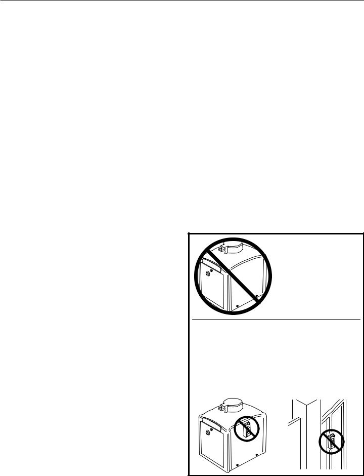
Table of Contents
Pre-installation Information . . . . . . . . . . . . . . . . . . . . . . . . . . . . . . . . . .1 Before You Begin... . . . . . . . . . . . . . . . . . . . . . . . . . . . . . . . . . . . . . .1 Always Check the Gate’s Action . . . . . . . . . . . . . . . . . . . . . . . . . . . .1 Gate Operator Classifi cations . . . . . . . . . . . . . . . . . . . . . . . . . . . . . .1 Approved Obstruction Detection Devices . . . . . . . . . . . . . . . . . . . . .1
Safety Information and Warnings. . . . . . . . . . . . . . . . . . . . . . . . . . . . . .1 Regulatory Warnings. . . . . . . . . . . . . . . . . . . . . . . . . . . . . . . . . . . . .1
Wiring Specifications . . . . . . . . . . . . . . . . . . . . . . . . . . . . . . . . . . . . . . .2 AC Power Wiring . . . . . . . . . . . . . . . . . . . . . . . . . . . . . . . . . . . . . . . .2 DC Control and Accessory Wiring. . . . . . . . . . . . . . . . . . . . . . . . . . .2
Mounting Pad Installation. . . . . . . . . . . . . . . . . . . . . . . . . . . . . . . . . . . .3 Mounting Pad Specifi cations . . . . . . . . . . . . . . . . . . . . . . . . . . . . . . .3
Operator Preparation . . . . . . . . . . . . . . . . . . . . . . . . . . . . . . . . . . . . . . .4 Vent Plug Installation. . . . . . . . . . . . . . . . . . . . . . . . . . . . . . . . . . . . .4
Gate Arm Installation . . . . . . . . . . . . . . . . . . . . . . . . . . . . . . . . . . . . . . .4 Setting Left or Right Hand Confi guration. . . . . . . . . . . . . . . . . . . . . .4 Gate Plate Installation . . . . . . . . . . . . . . . . . . . . . . . . . . . . . . . . . . . .4 Choosing Good Harmonics . . . . . . . . . . . . . . . . . . . . . . . . . . . . . . . .5 Installing the Gate Arm on the Operator . . . . . . . . . . . . . . . . . . . . . .5 Setting the Arm Lengths . . . . . . . . . . . . . . . . . . . . . . . . . . . . . . . . . .5
Operator Setup . . . . . . . . . . . . . . . . . . . . . . . . . . . . . . . . . . . . . . . . . . . .6 Controller Access . . . . . . . . . . . . . . . . . . . . . . . . . . . . . . . . . . . . . . .6 AC Power Connection . . . . . . . . . . . . . . . . . . . . . . . . . . . . . . . . . . . .6 Earth Ground. . . . . . . . . . . . . . . . . . . . . . . . . . . . . . . . . . . . . . . . . . .6 Limit Cam Rough Adjustment . . . . . . . . . . . . . . . . . . . . . . . . . . . . . .7 Torque Limiter Adjustment. . . . . . . . . . . . . . . . . . . . . . . . . . . . . . . . .7 Limit Cam Fine Adjustment . . . . . . . . . . . . . . . . . . . . . . . . . . . . . . . .7
Controller Features . . . . . . . . . . . . . . . . . . . . . . . . . . . . . . . . . . . . . . . . .8 Indicator Descriptions. . . . . . . . . . . . . . . . . . . . . . . . . . . . . . . . . . . . . . .9 Terminal Descriptions . . . . . . . . . . . . . . . . . . . . . . . . . . . . . . . . . . . . . .10 Operator Accessory Connections . . . . . . . . . . . . . . . . . . . . . . . . . . . .11
Basic Controller Programming. . . . . . . . . . . . . . . . . . . . . . . . . . . . . . .12 Programming Overview . . . . . . . . . . . . . . . . . . . . . . . . . . . . . . . . . .12 Entering Programming Mode . . . . . . . . . . . . . . . . . . . . . . . . . . . . .12 Exiting Programming Mode . . . . . . . . . . . . . . . . . . . . . . . . . . . . . . .12 Programming Keystrokes . . . . . . . . . . . . . . . . . . . . . . . . . . . . . . . .12 Left or Right Hand Operation. . . . . . . . . . . . . . . . . . . . . . . . . . . . . .12 Dual Gate Enable . . . . . . . . . . . . . . . . . . . . . . . . . . . . . . . . . . . . . .12 Auto Close Timer. . . . . . . . . . . . . . . . . . . . . . . . . . . . . . . . . . . . . . .12 Run Alarm and Pre-start Alarm. . . . . . . . . . . . . . . . . . . . . . . . . . . .13 Maximum Open Direction Current Setting. . . . . . . . . . . . . . . . . . . .13 Maximum Close Direction Current Setting . . . . . . . . . . . . . . . . . . .13
Advanced Controller Programming . . . . . . . . . . . . . . . . . . . . . . . . . . .14 Entering Advanced Programming Mode . . . . . . . . . . . . . . . . . . . . .14 Maximum Run Time . . . . . . . . . . . . . . . . . . . . . . . . . . . . . . . . . . . .14 Single Button Input Setup . . . . . . . . . . . . . . . . . . . . . . . . . . . . . . . .14 Stagger Mode . . . . . . . . . . . . . . . . . . . . . . . . . . . . . . . . . . . . . . . . .14 Stagger Delay Time. . . . . . . . . . . . . . . . . . . . . . . . . . . . . . . . . . . . .14 Auxiliary Relay Mode. . . . . . . . . . . . . . . . . . . . . . . . . . . . . . . . . . . .15 Reverse Delay Time . . . . . . . . . . . . . . . . . . . . . . . . . . . . . . . . . . . .15 Low Power Mode . . . . . . . . . . . . . . . . . . . . . . . . . . . . . . . . . . . . . . .15 Power Failure Mode. . . . . . . . . . . . . . . . . . . . . . . . . . . . . . . . . . . . .15 Soft Start/Stop Duration . . . . . . . . . . . . . . . . . . . . . . . . . . . . . . . . .16 Reset Cycle Count . . . . . . . . . . . . . . . . . . . . . . . . . . . . . . . . . . . . .16 Maintenance Alert Trigger . . . . . . . . . . . . . . . . . . . . . . . . . . . . . . . .16 Mid-travel Stop Position. . . . . . . . . . . . . . . . . . . . . . . . . . . . . . . . . .16 Motor Type Selection . . . . . . . . . . . . . . . . . . . . . . . . . . . . . . . . . . . .16 Radio Enable. . . . . . . . . . . . . . . . . . . . . . . . . . . . . . . . . . . . . . . . . .17 Antenna Installation. . . . . . . . . . . . . . . . . . . . . . . . . . . . . . . . . . . . .17 Radio Transmitter Learn . . . . . . . . . . . . . . . . . . . . . . . . . . . . . . . . .17 Radio Transmitter Delete . . . . . . . . . . . . . . . . . . . . . . . . . . . . . . . . .17 MGT Obstacle Transmitter Learn . . . . . . . . . . . . . . . . . . . . . . . . . .17 MGT Obstacle Transmitter Delete . . . . . . . . . . . . . . . . . . . . . . . . . .17 Reset Controller to Factory Defaults . . . . . . . . . . . . . . . . . . . . . . . .17
Loop Layout Illustration . . . . . . . . . . . . . . . . . . . . . . . . . . . . . . . . . . . .18 Safety Edge Layout Illustration . . . . . . . . . . . . . . . . . . . . . . . . . . . . . .19
Photoeye Installation Illustration . . . . . . . . . . . . . . . . . . . . . . . . . . . . .20
Dual Gate Installations . . . . . . . . . . . . . . . . . . . . . . . . . . . . . . . . . . . . .21
Gate Operation. . . . . . . . . . . . . . . . . . . . . . . . . . . . . . . . . . . . . . . . . . . .21 Open Button . . . . . . . . . . . . . . . . . . . . . . . . . . . . . . . . . . . . . . . . . .21 Close Button . . . . . . . . . . . . . . . . . . . . . . . . . . . . . . . . . . . . . . . . . .21 Stop Button . . . . . . . . . . . . . . . . . . . . . . . . . . . . . . . . . . . . . . . . . . .21 Single Input . . . . . . . . . . . . . . . . . . . . . . . . . . . . . . . . . . . . . . . . . . .21 Fire Department Input . . . . . . . . . . . . . . . . . . . . . . . . . . . . . . . . . . .21 Open Input. . . . . . . . . . . . . . . . . . . . . . . . . . . . . . . . . . . . . . . . . . . .21 Open Obstruction . . . . . . . . . . . . . . . . . . . . . . . . . . . . . . . . . . . . . .21 Close Obstruction . . . . . . . . . . . . . . . . . . . . . . . . . . . . . . . . . . . . . .21 Reverse Input . . . . . . . . . . . . . . . . . . . . . . . . . . . . . . . . . . . . . . . . .21
SWR • SWC • SWD Swing Gate Operator Installation Guide
Open Loop. . . . . . . . . . . . . . . . . . . . . . . . . . . . . . . . . . . . . . . . . . . .21 Reverse Loop . . . . . . . . . . . . . . . . . . . . . . . . . . . . . . . . . . . . . . . . .21 Shadow/Reset Loop . . . . . . . . . . . . . . . . . . . . . . . . . . . . . . . . . . . .21
Operation Indications . . . . . . . . . . . . . . . . . . . . . . . . . . . . . . . . . . . . . .22 Power-up Display. . . . . . . . . . . . . . . . . . . . . . . . . . . . . . . . . . . . . . .22 Idle Condition . . . . . . . . . . . . . . . . . . . . . . . . . . . . . . . . . . . . . . . . .22 Last Gate Position/Condition . . . . . . . . . . . . . . . . . . . . . . . . . . . . . .22 Pre-start Delay . . . . . . . . . . . . . . . . . . . . . . . . . . . . . . . . . . . . . . . .22 Reverse Delay . . . . . . . . . . . . . . . . . . . . . . . . . . . . . . . . . . . . . . . . .22 Run Timer . . . . . . . . . . . . . . . . . . . . . . . . . . . . . . . . . . . . . . . . . . . .22
Error Indications . . . . . . . . . . . . . . . . . . . . . . . . . . . . . . . . . . . . . . . . . .22 Entrapment . . . . . . . . . . . . . . . . . . . . . . . . . . . . . . . . . . . . . . . . . . .22 COMM LINK Connection Failure . . . . . . . . . . . . . . . . . . . . . . . . . . .22 MGT Obstacle Transmitter Trouble . . . . . . . . . . . . . . . . . . . . . . . . .22 Maximum Run Time Exceeded . . . . . . . . . . . . . . . . . . . . . . . . . . . .22
Troubleshooting. . . . . . . . . . . . . . . . . . . . . . . . . . . . . . . . . . . . . . . . . . .23 Contacting Technical Support . . . . . . . . . . . . . . . . . . . . . . . . . . . . .23 Operator fails to start. . . . . . . . . . . . . . . . . . . . . . . . . . . . . . . . . . . .23 Motor operates, but gate does not move. . . . . . . . . . . . . . . . . . . . .23 Motor sounds like it is working harder than normal . . . . . . . . . . . . .23 Limit switch getting out of time . . . . . . . . . . . . . . . . . . . . . . . . . . . .23 Gate stopping part way open or closed (but no visible obstruction) 23 Gate staying open with automatic system . . . . . . . . . . . . . . . . . . . .23 How to Order Replacement Parts . . . . . . . . . . . . . . . . . . . . . . . . . .23
Model SWR Exploded View. . . . . . . . . . . . . . . . . . . . . . . . . . . . . . . . . .24 Model SWC Exploded View. . . . . . . . . . . . . . . . . . . . . . . . . . . . . . . . . .25
Model SWD Exploded View. . . . . . . . . . . . . . . . . . . . . . . . . . . . . . . . . .26
SWR, SWC, SWD Gate Arm Assembly Exploded View. . . . . . . . . . . .27
Model SWD Maintenance . . . . . . . . . . . . . . . . . . . . . . . . . . . . . . . . . . .28 Battery Maintenance . . . . . . . . . . . . . . . . . . . . . . . . . . . . . . . . . . . .28 DC Motor Brush Replacement . . . . . . . . . . . . . . . . . . . . . . . . . . . .28
Preventative Maintenance . . . . . . . . . . . . . . . . . . . . . . . . . . . . . . . . . .29 General . . . . . . . . . . . . . . . . . . . . . . . . . . . . . . . . . . . . . . . . . . . . . .29 Lubrication. . . . . . . . . . . . . . . . . . . . . . . . . . . . . . . . . . . . . . . . . . . .29 6-Month Preventative Maintenance. . . . . . . . . . . . . . . . . . . . . . . . .29
FCC Notice . . . . . . . . . . . . . . . . . . . . . . . . . . . . . . . . . . . . . . . . . . . . . . .29
Gate Operator Installation Checklist . . . . . . . . . . . . . . . . . . . . . . . . . .30
 WARNING
ONLY QUALIFIED TECHNICIANS
SHOULD WORK ON
LINEAR SWING GATE
OPERATORS
 WARNING
CONTROLS INTENDED FOR USER ACTIVATION MUST BE LOCATED AT LEAST SIX FEET (6') AWAY FROM ANY MOVING PART OF THE GATE AND WHERE THE USER IS PREVENTED FROM REACHING OVER, UNDER, AROUND OR THROUGH THE GATE TO OPERATE THE CONTROLS. OUTDOOR OR EASILY ACCESSIBLE CONTROLS SHALL HAVE A SECURITY FEATURE TO PREVENT UNAUTHORIZED USE.
227965 Revision X13 3-28-2008
Pre-installation Information |
|
|
Safety Information and Warnings |
|||||
Before You Begin... |
|
|
THE FOLLOWING FORMATS ARE USED FOR SAFETY NOTES |
|||||
|
|
|
|
IN THESE INSTRUCTIONS. |
||||
Before unpacking, inspect the carton for exterior damage. If |
|
|
||||||
|
|
|
|
|||||
|
|
CAUTION |
|
|||||
you fi nd damage, advise the delivery carrier of a potential |
|
|
|
|||||
claim. Inspect your package carefully. You can check your |
|
|
This type of warning note is used to |
|
||||
accessory box parts with the enclosed packing slip for your |
|
|
indicate the possibility of damage to the |
|
||||
convenience. Claims for shortages will be honored for only |
|
|
gate or gate operator. |
|
||||
30 days from the date of shipment. |
|
|
|
|
|
|
||
|
|
|
|
WARNING |
|
|||
Before installing the operator, read this manual completely to |
|
|
|
|||||
|
|
This type of warning note is used to |
||||||
ensure all requirements for proper installation are present.Verify |
|
|
|
|||||
|
|
indicate possible mechanical hazards that |
|
|||||
that the voltage to be used matches the voltage of the operator. |
|
|
|
|||||
|
|
may cause serious injuries or death. |
|
|||||
If you have any questions about the requirements for proper |
|
|
|
|||||
|
|
|
|
|||||
installation of this gate operator contact technical support at |
|
|
WARNING |
|
||||
|
|
|
|
|||||
800-421-1587 |
|
|
|
|
|
|
||
|
|
|
|
This type of warning note is used to indicate |
|
|||
|
|
|
|
|
|
|
||
Always Check the Gate’s Action |
|
|
|
|
possible electrical shock hazards that may |
|
||
It’s very important before installing the gate operator to |
|
|
cause serious injuries or death. |
|
||||
Regulatory Warnings |
||||||||
make sure the gate’s swing is free and level throughout |
||||||||
the entire swing path. If the gate does not seem to |
Read the following before beginning to install this swing |
|||||||
operate properly, it may affect the operator performance |
gate operator: |
|||||||
or greatly shorten the life of the unit. The gate should |
|
|
|
|
||||
IMPORTANT INSTALLATION SAFETY INSTRUCTIONS |
||||||||
also be designed so that airflow is ample to prevent |
||||||||
wind resistance and drag. |
|
|
|
|
WARNING |
|||
|
|
|
|
|
|
|||
Gate Operator Classifications |
|
|
|
|
|
|
||
|
|
TO REDUCE THE RISK OF SEVERE INJURY OR DEATH |
||||||
All gate operators can be divided into one of four different |
||||||||
TO PERSONS, REVIEW THESE INSTALLATION SAFETY |
||||||||
classifi cations, depending on their design and usage. Install |
||||||||
this gate operator only when the operator is appropriate for |
|
|
STEPS BEFORE PROCEEDING |
|||||
|
|
|
|
|||||
the construction and usage class as defi ned below: |
|
|
1. |
READ AND FOLLOW ALL INSTALLATION INSTRUCTIONS. |
||||
• Class I Residential Vehicular Gate Operator |
|
|
||||||
|
|
2. |
Read the yellow “Safety Instructions” brochure enclosed with the |
|||||
|
A vehicular gate operator intended for use in a home or for one to |
|||||||
|
|
packet of information. If any pages are missing or are unreadable, |
||||||
|
four single family dwellings with a common garage or parking area |
|
||||||
|
|
or you do not have the safety instructions, please call Linear at |
||||||
|
associated with these dwellings. |
|
|
|
1-800-421-1587 to request additional copies. |
|||
• Class II Commercial / General Access Vehicular Gate Operator |
|
|
3. |
ALL ELECTRICAL CONNECTIONS TO THE POWER SUPPLY MUST |
||||
|
A vehicular gate operator intended for use in a commercial location or |
|
BE MADE BY A LICENSED ELECTRICIAN AND MUST OBSERVE ALL |
|||||
|
|
NATIONAL AND LOCAL ELECTRICAL CODES. |
||||||
|
building such as a multi-family housing unit of fi ve or more single family |
|
||||||
|
4. |
A separate power-disconnect switch should be located near the |
||||||
|
units, hotel, retail store or other building servicing the general public. |
|
|
|||||
|
|
|
|
operator so that primary power can be turned off when necessary. |
||||
• Class III Industrial / Limited Access Vehicular Gate Operator |
|
|
|
|||||
|
|
5. |
Install the enclosed warning signs on both sides of the gate. A |
|||||
|
A vehicular gate operator intended for use in an industrial location or |
|
minimum of two (2) WARNING SIGNS shall be installed, one on each |
|||||
|
building such as a factory or loading dock area or other location not |
|
side of the gate where easily visible. |
|||||
|
intended to service the general public. |
|
|
6. |
Never reach between, through or around the fence to operate the |
|||
• Class IV Restricted Access Vehicular Gate Operator |
|
|
|
gate. |
||||
|
|
7. |
Never connect a button station within reach of the gate or on the |
|||||
|
A vehicular gate operator intended for use in a guarded industrial |
|||||||
|
|
side of the gate operator. |
||||||
|
location or building such as an airport security area or other restricted |
|
||||||
|
8. |
Do not adjust the operator controller’s current sensing feature too |
||||||
|
access locations not servicing the general public, in which unauthorized |
|||||||
|
|
high. It should be adjusted high enough to keep the gate from falsely |
||||||
|
access is prevented via supervision by security personnel. |
|
|
|
||||
|
|
|
|
triggering the sensing, but no higher than necessary for the gate to |
||||
Approved Obstruction Detection Devices |
|
|
|
operate. DO NOT DEFEAT THE PURPOSE OF THIS FUNCTION! |
||||
|
|
9. |
You must install all required safety equipment. |
|||||
The following contact or non-contact obstruction detection |
||||||||
10. |
UL325 Compliance requires the use of contact edges or photoelectric |
|||||||
devices have been approved for use with this swing gate |
|
controls on all automatic or remotely-controlled gate operators. |
||||||
operator as part of a UL325 compliant installation: |
|
|
11. |
The operator is intended for installation only on gates used for |
||||
• |
Contact Edges |
|
|
|
vehicles. Pedestrians must be supplied with a separate access |
|||
|
|
|
opening. The pedestrian access opening shall be designed to |
|||||
|
Miller Edge Models MGO20, MGR20, MGS20, ME120 |
|
|
|
||||
|
|
|
|
promote pedestrian usage. Locate the gate such that persons will |
||||
• |
Photoeyes |
|
|
|
||||
|
|
|
not come into contact with the vehicular gate during the entire path |
|||||
|
MMTC Model IR-55 (165’ range - P/N 2520-441) |
|
|
|
of travel of the vehicular gate. |
|||
|
MMTC Model E3K (28’ range - P/N 2520-031) |
|
|
|
|
|
|
|
|
|
|
|
|
||||
SWR • SWC • SWD Swing Gate Operator Installation Guide |
- 1 - |
|
|
227965 Revision X13 3-28-2008 |
||||

Wiring Specifications
Refer to the following steps for details on power and accessory wiring for the operator.
 WARNING
ALL AC ELECTRICAL CONNECTIONS TO THE POWER SOURCE AND THE OPERATOR MUST BE MADE BY A LICENSED ELECTRICIAN AND MUST OBSERVE ALL NATIONAL AND LOCAL ELECTRICAL CODES.
USE COPPER WIRE ONLY!
AC Power Wiring
1.Find the listing on this page corresponding to the model, voltage and horsepower rating of your operator.
2.The distance shown in the table is measured in feet from the operator to the power source. DO NOT EXCEED THE MAXIMUM DISTANCE. These calculations have been based on standard 115 V and 230 V supplies with a 10% drop allowable. If your supply is under the standard rating, the runs listed may be longer than what your application will handle, and you should not run wire too near the maximum distance for the gauge of wire you are using.
3.When large-gauge wire is used, a separate junction box (not supplied) may be needed for the operator power connection.
4.Wire length calculations are based on the National Electrical Code, Article 430 and have been carefully determined based on motor inrush, brake solenoids, and operator requirements.
5.Connect power in accordance with local codes. The green ground wire must be properly connected.
6.Wire insulation must be suitable to the application.
7.Electrical outlets are supplied in all 115 VAC models for convenience with occasional use or low power consumption devices only. If you choose to run dedicated equipment from these devices, it will decrease the distance for maximum length and the charts will no longer be accurate.
DC Control and Accessory Wiring
1.All control devices are now 24 VDC, which can be run up to 2000 feet with 14 AWG wire.
2.Control wiring must be run in a separate conduit from power wiring. Running them together may cause interference and faulty signals in some accessories.
3.A three-wire shielded conductor cable is required to connect two operators together for dual operation. You must use Belden 8760 Twisted Pair Shielded Cable (or equivalent) only – P/N 2500-1982, per foot). See Page 21 for details of this connection. Note:The shield wire should be connected in both the operators.
MODEL SWR POWER WIRING
VOLTS & HP |
MAXIMUM DISTANCE (FEET) |
WIRE GAUGE |
||
SINGLE |
DUAL |
|||
|
|
|||
|
316 |
158 |
12 |
|
115 VOLTS |
502 |
251 |
10 |
|
800 |
400 |
8 |
||
1/2-HP |
||||
1272 |
636 |
6 |
||
|
||||
|
2022 |
1011 |
4 |
|
|
764 |
382 |
12 |
|
230 VOLTS |
1218 |
609 |
10 |
|
1936 |
968 |
8 |
||
1/2-HP |
||||
3076 |
1538 |
6 |
||
|
||||
|
4896 |
2448 |
4 |
|
|
|
|
||
|
MODEL SWC POWER WIRING |
|
||
VOLTS & HP |
MAXIMUM DISTANCE (FEET) |
WIRE GAUGE |
||
SINGLE |
DUAL |
|||
|
|
|||
|
222 |
111 |
12 |
|
115 VOLTS |
354 |
177 |
10 |
|
566 |
283 |
8 |
||
1/2-HP |
||||
900 |
450 |
6 |
||
|
||||
|
1430 |
715 |
4 |
|
|
178 |
89 |
12 |
|
115 VOLTS |
282 |
141 |
10 |
|
450 |
255 |
8 |
||
3/4-HP |
||||
716 |
358 |
6 |
||
|
||||
|
1140 |
570 |
4 |
|
|
160 |
80 |
12 |
|
115 VOLTS |
254 |
127 |
10 |
|
406 |
203 |
8 |
||
1-HP |
||||
646 |
323 |
6 |
||
|
||||
|
1026 |
513 |
4 |
|
|
760 |
380 |
12 |
|
208 VOLTS |
1200 |
600 |
10 |
|
1924 |
962 |
8 |
||
1/2-HP |
||||
3060 |
1830 |
6 |
||
|
||||
|
4864 |
2432 |
4 |
|
|
604 |
302 |
12 |
|
208 VOLTS |
958 |
478 |
10 |
|
1526 |
763 |
8 |
||
3/4-HP |
||||
2424 |
1212 |
6 |
||
|
||||
|
3856 |
1928 |
4 |
|
|
544 |
272 |
12 |
|
208 VOLTS |
864 |
432 |
10 |
|
1374 |
686 |
8 |
||
1-HP |
||||
2184 |
1092 |
6 |
||
|
||||
|
3476 |
1738 |
4 |
|
|
894 |
447 |
12 |
|
230 VOLTS |
1422 |
711 |
10 |
|
2264 |
1132 |
8 |
||
1/2-HP |
||||
3600 |
1800 |
6 |
||
|
||||
|
5724 |
2862 |
4 |
|
|
710 |
355 |
12 |
|
230 VOLTS |
1128 |
564 |
10 |
|
1796 |
898 |
8 |
||
3/4-HP |
||||
2852 |
1426 |
6 |
||
|
||||
|
4538 |
2269 |
4 |
|
|
640 |
320 |
12 |
|
230 VOLTS |
1016 |
508 |
10 |
|
1616 |
808 |
8 |
||
1-HP |
||||
2570 |
1285 |
6 |
||
|
||||
|
4090 |
2045 |
4 |
|
|
|
|
||
|
MODEL SWD POWER WIRING |
|
||
VOLTS & HP |
MAXIMUM DISTANCE (FEET) |
WIRE GAUGE |
||
SINGLE |
DUAL |
|||
|
|
|||
|
970 |
485 |
12 |
|
115 VOLTS |
1542 |
771 |
10 |
|
2452 |
1226 |
8 |
||
1/2-HP |
||||
3898 |
1949 |
6 |
||
|
||||
|
6200 |
3100 |
4 |
|
SWR • SWC • SWD Swing Gate Operator Installation Guide |
- 2 - |
227965 Revision X13 3-28-2008 |
Mounting Pad Installation
The gate operator mounts bolted to a custom poured concrete mounting pad. The pad supports the operator and prevents it from twisting during operation.
An optional post mount kit is also available (P/N 2120-483) which allows installation without a concrete mounting pad.
WARNING
The operator is intended for installation only on gates used for vehicles. Pedestrians must be supplied with a separate access opening. The pedestrian access opening shall be designed to promote pedestrian usage. Locate the gate such that persons will not come into contact with the vehicular gate during the entire path of travel of the vehicular gate.
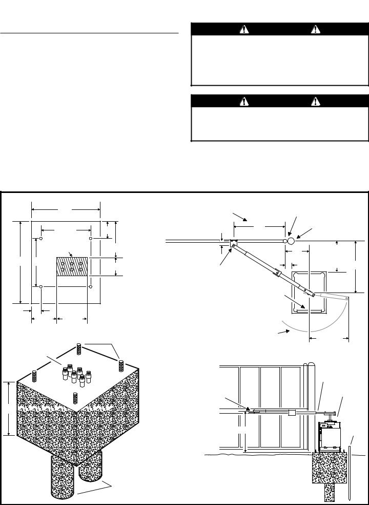
Mounting Pad Specifications
Recommended pad size is 24” x 20” x 18” deep minimum. Pad depth should be set according to local codes and at least as deep as frost line.
If soil conditions may cause the operator and pad to shift or twist during operation, anti-rotation legs may be required. Use two 6” diameter, 10” deep legs to counteract this problem as shown.
5/8” J-bolts may be set into the concrete before it sets following the dimensions shown, or drilled after the concrete sets.
WARNING
The gate must be installed in a location so that enough clearance is supplied between the gate and adjacent structures when opening and closing to reduce the risk of entrapment. Swing gates shall not open into public areas.
NOTE: Maximum gate opening angle is approximately 95 degrees, depending on gate width. If larger opening angle is required, non-standard positioning of the operator and modified articulating arms may be required. Contact the factory for technical information, pricing, and availability.
|
GATE LINE ON THIS SIDE |
"W" DIMENSION IS 33" FOR |
GATE TOP VIEW |
|
|
||||
|
|
20" |
|
STANDARD APPLICATIONS |
|
GATE HINGE |
|
||
|
|
|
(GATE ARM ACCOMODATES |
|
|
||||
|
|
|
|
|
|
||||
|
|
|
|
TO 40" "W" IF EXTRA SPACE |
|
|
|
|
|
|
|
14-1/2" |
5" |
IS REQUIRED) |
W |
|
GATE POST |
|
|
|
|
|
|
(TYP. 33") |
|
|
|
||
|
|
|
|
|
|
|
|
|
|
|
|
CONDUIT |
10-1/2" |
|
|
|
|
W |
|
|
|
ENTRY ZONE |
|
2-3/4" |
|
17" |
|
||
|
|
|
|
|
|
MINUS |
|
||
24" |
14" |
|
|
|
|
7" |
|
|
|
|
5" |
|
|
|
12" |
W |
|||
|
|
|
|
GATE PLATE |
|
||||
|
|
|
|
|
|
|
|
|
|
|
|
|
INSTALLER TIP: |
|
ARM HOLE |
|
|
|
|
|
|
|
|
2-3/4" BEHIND |
OPERATOR |
|
|
|
|
|
|
|
MAKE A WOOD JIG TO |
|
CENTERLINE |
|
|
|
|
|
|
|
|
ACCESS DOOR |
|
|
|
||
|
|
|
ALIGN AND HOLD J-BOLTS |
OF GATE |
|
|
|
||
|
|
|
FACES AWAY |
|
|
|
|||
|
|
|
AND CONDUITS UNTIL |
|
|
|
|
|
|
|
|
|
|
|
FROM GATE LINE |
|
|
|
|
2-3/4" |
|
|
THE CONCRETE SETS |
|
|
|
|
|
|
|
|
|
|
|
|
|
|
||
|
6-3/4" |
8-1/2" |
|
|
|
|
|
|
|
|
|
|
5/8" x 8" |
|
BACKSPACE REQUIREMENT |
|
|
|
|
|
|
|
|
FOR ARM SWING IS 25" STANDARD OR |
|
25" - 30" |
|
||
|
|
|
J-BOLTS (4) |
|
UP TO 30" WITH FULL ARM EXTENSION |
|
|
||
1/2" FLEX |
|
|
|
|
|
|
|
|
|
CONDUIT |
|
|
|
|
|
|
|
|
|
INSIDE VIEW OF GATE
TOP OF GATE PLATE 24-7/8" ABOVE THE TOP OF THE PAD
18" 


CONCRETE |
24-7/8" |
|
|
OPERATOR |
|
PAD 3D VIEW |
|
IN SOFT SOIL, POUR |
"RIGHT-HAND" |
TWO 6" DIAMETER |
INSTALLATION |
10" DEEP "LEGS" TO |
|
PREVENT ROTATION |
|
GATE ARM
OPERATOR
EARTH
GROUND
STAKE
Figure 1. Mounting Pad Specifications
SWR • SWC • SWD Swing Gate Operator Installation Guide |
- 3 - |
227965 Revision X13 3-28-2008 |
Operator Preparation
Vent Plug Installation
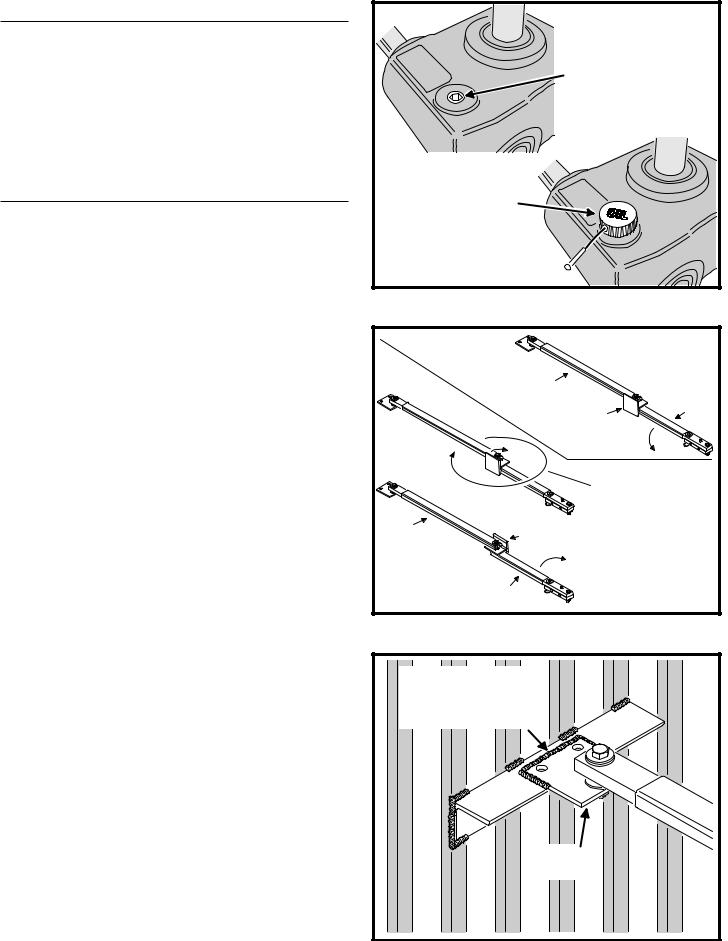
In order to keep gear oil from spilling out during shipping, gear reducers used in gate operators have either a solid plug, or a sealed vent plug, installed at the factory.
For operators with a solid plug, replace the solid plug with the vent plug provided (see Figure 2).
With the vent plug installed, remove the vent plug’s breather pin to allow the gear box to vent (see Figure 2).
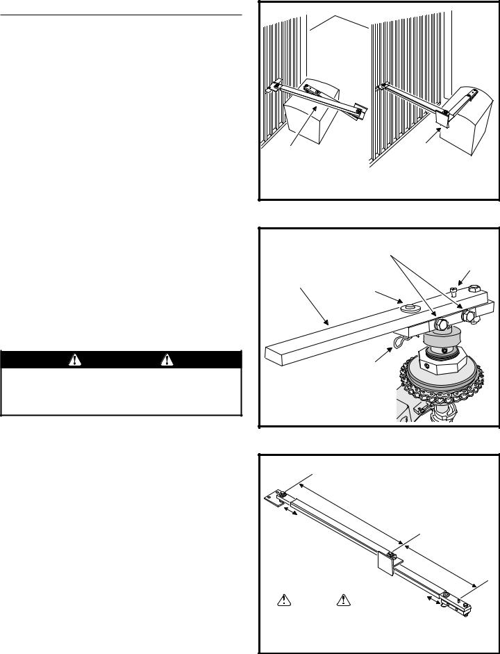
Gate Arm Installation
The gate arm connects the operator to the gate. The arm supplied can be used in left-hand or right-hand installations. After the proper length of the crank extension and link section of the arm has been determined, the arm is welded to complete the assembly.
Setting Left or Right Hand Configuration
The welded style gate arm has been pre-assembled at the factory in right-hand confi guration (the back of the overtravel stop faces toward the drive when the gate is fully closed and the arm is installed). For a left-hand operator, rotate the upper portion of the arm as shown in Figure 3 to convert the arm into a left-hand orientation.
Gate Plate Installation
The gate plate mounts on the gate at the recommended height (24-7/8” above the top of the operator pad). The gate plate supplied with the arm assembly can be welded to the gate as shown in Figure 4. Holes have been provided for securing the gate plate to an aluminum gate.
GEAR
REDUCER
REMOVE THE
SOLID PLUG
WITH AN ALLEN
WRENCH
INSTALL THE VENT PLUG
(IF NOT ALREADY INSTALLED)
REMOVE THE
BREATHER PIN 

Figure 2. Vent Plug Installation
RIGHT-HAND
CONFIGURATION (AS SHIPPED)
VIEWED FROM INSIDE, |
|
THE OPERATOR IS ON |
|
THE RIGHT SIDE OF GATE |
|
LINK |
|
ARM |
CRANK |
|
|
OVERTRAVEL |
ARM |
|
|
STOP ON |
|
THIS SIDE |
|
|
OPEN |
|
|
TO CHANGE THE GATE ARM, |
|
|
ROTATE THE LINK END AND |
|
|
OVERTRAVEL STOP |
|
|
ALL THE WAY AROUND |
LINK |
OVERTRAVEL |
|
ARM |
|
STOP ON |
|
THIS SIDE |
|
|
LEFT-HAND |
OPEN |
|
CONFIGURATION |
VIEWED FROM INSIDE, |
|
|
|
|
CRANK |
THE OPERATOR IS ON |
|
ARM |
THE LEFT SIDE OF GATE |
Figure 3. Left or Right Hand Gate Arm Setup
WELD THE GATE PLATE
TO THE GATE (AN EXTRA
SUPPORT WELDED TO THE
GATE MAY BE REQUIRED)
GATE PLATE
LINK ASSEMBLY
Figure 4. Gate Plate Installation
SWR • SWC • SWD Swing Gate Operator Installation Guide |
- 4 - |
227965 Revision X13 3-28-2008 |
Gate Arm Installation (Cont.)
Choosing Good Harmonics
Good harmonics are necessary to minimize wear and tear on the operator.The gate will have smoother starts and stops when the arm is installed with good harmonics. Figure 5 shows an example of good and bad arm harmonics.
Installing the Gate Arm on the Operator
The hex cap screws (see Figure 6) in the side of the crank assembly are shipped loose for placement on the operator drive shaft. Once in place, tighten these cap screws in place by applying 75 ft-lbs of torque. If it becomes necessary to remove the crank, you can do so by loosening these bolts. The arm can also be disconnected for manual operation of the gate by removing the disconnect pin.
Setting the Arm Lengths
Most installations will use the standard dimensions specifi ed. The dimensions shown in Figure 7 can be used to adjust and set the arm. If non-standard mounting is required, contact the factory for information.
Once the arm lengths have been determined, use clamps to temporarily attach the solid bars to their sections of rectangular tubing. If clamps are unavailable, you may also tack weld the parts in place. It is recommended that you check the arm for proper action and full gate travel before fully welding the parts together. REMOVE THE GATE ARM BEFORE WELDING! Apply Krylon® metallic gold spray paint or equivalent to touch up welds when fi nished.
CAUTION
DO NOT WELD THE GATE ARM WHILE IT IS ATTACHED TO THE OPERATOR! Connecting the welder’s ground to the operator’s frame will cause the arc welding current to pass through the operator parts, severely damaging or destroying the operator.
GATES SHOWN OPEN
GOOD
HARMONICS
GATE ARM FOLDS
OVER ITSELF
GATE WILL HAVE SOFT
STARTS AND STOPS
BAD
HARMONICS!
CRANK END OF
GATE ARM PARALLEL
TO OPEN GATE
GATE ARM JERKS AT START AND WILL TRANSMIT FORCE INTO GATE AND HARDWARE
Figure 5. Gate Arm Harmonics
|
ALIGN CRANK ARM ON OPERATOR |
|
THEN TIGHTEN THESE TWO BOLTS |
|
RAIN CAP |
|
SHOLDER BOLT |
CRANK END OF |
|
GATE ARM |
DISCONNECT |
|
PIN |
|
PULL |
|
PIN |
Figure 6. Installing Gate Arm on Operator
A |
|
|
LINK |
|
|
ARM |
|
|
36-1/2" |
|
|
TYPICAL |
|
|
SET LENGTH |
C |
CRANK |
AND WELD |
||
|
|
ARM |
|
|
22" |
|
|
TYPICAL |
|
|
B |
CAUTION! |
|
|
CLAMP OR TACK WELD, |
SET LENGTH |
|
AND WELD |
|
|
THEN TEST ARM ACTION |
|
|
|
|
|
BEFORE FULLY WELDING |
|
|
Figure 7. Setting Gate Arm Lengths
SWR • SWC • SWD Swing Gate Operator Installation Guide |
- 5 - |
227965 Revision X13 3-28-2008 |
Operator Setup
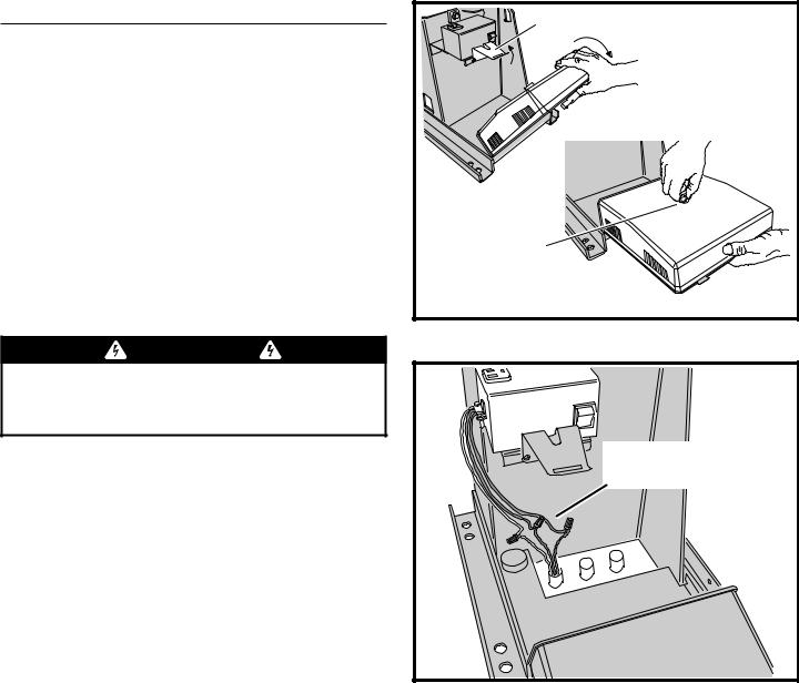
Controller Access
The Controller in models SWR, SWC and SWD is hinged for access and can be removed without taking off the operator’s cover. It swings down for installation, programming, and troubleshooting access (see Figure 8). Under most circumstances you will not need to remove the Controller.
To access the Controller, lift the metal tab below the AC power switch and swing the Controller down. The Controller is protected by a plastic dust cover. To remove the dust cover, loosen the cover’s wing-screw and lift the cover off.
To remove the Controller from the operator, slide the assembly to the right until the hinges release. Once freed, you can turn the Controller slightly and remove it from the operator. Be careful not to pull on the cables too hard.
AC Power Connection
 WARNING
ALL AC ELECTRICAL CONNECTIONS TO THE POWER SOURCE AND THE OPERATOR MUST BE MADE BY A LICENSED ELECTRICIAN AND MUST OBSERVE ALL NATIONAL AND LOCAL ELECTRICAL CODES
AllLineargateoperatorsaresuppliedwithapowerdisconnect switch to turn on and off the power available to the operator (see Figure 9). Following wiring specifi cations on Page 2, incoming power should be brought into the operator and connected to the labeled pigtails from the disconnect box. A wiring connections print can be found on the label inside the cover of the operator.
Proper thermal protection is supplied with the operator. The motor contains a thermal overload protector to guard from overheating the motor due to overload or high-frequency operation. This overload protector will reset automatically after the motor cools down.
Earth Ground
Install a ground rod and connect it to the operator’s frame in every gate operator installation. A good earth ground is necessary to allow the Controller’s built-in surge and lightning protection circuitry to work effectively. The physical bolting of the operator to the mounting pad is not sufficient for a good earth ground.
NOTE: Do not splice the ground wire. Use a single piece of solid copper 12 AWG wire between the ground rod and the operator.
1.Install an 8-foot long copper ground rod next to the operator mounting pad within three feet of the operator.
2.Use a clamp to connect a solid copper 12 AWG ground wire to the ground rod.
3.Route the ground wire to the operator.
4.Connect the ground wire to the operator’s frame.
LIFT UP ON TAB
CONTROLLER SWINGS DOWN
UNSCREW KNOB
TO REMOVE
CONTROLLER
COVER
Figure 8. Controller Access
115 VAC WIRING GREEN - GROUND BLACK - HOT WHITE - NEUTRAL
CONNECT AC POWER
PIGTAIL LEADS TO
THE AC SOURCE
230 VAC WIRING GREEN - GROUND BLACK - LINE 1 BLACK - LINE 2
Figure 9. Power Disconnect Box Wiring
SWR • SWC • SWD Swing Gate Operator Installation Guide |
- 6 - |
227965 Revision X13 3-28-2008 |
Operator Setup (Continued)
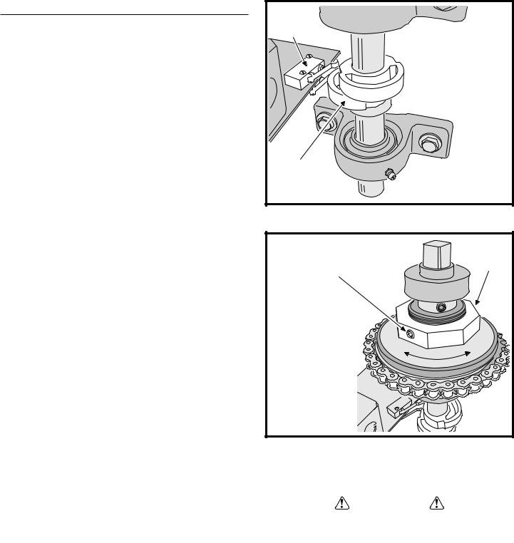
Limit Cam Rough Adjustment
The limit cams are not preset at the factory and must be adjusted for each installation. The limit switches are activated by two rotating limit cams attached to the drive shaft (see Figure 10). The Controller is factory set for right hand installations. The top cam is for OPEN and the bottom cam is for CLOSE. The cams fl ip their defi nition in left hand installations (see left-right hand programming on Page 12).
1.With the gate connected to the gate operator in a mid-travel position, the power disconnect switch turned OFF, and the torque limiter set loose enough to slip freely, manually move the gate by hand to its fully open position.
2.Once the gate is in the fully open position, set the OPEN limit cam so that it has just triggered its switch (see Figure 10).
3.Manually move the gate to its fully closed position, set the CLOSE limit cam so that it has just triggered its switch (see Figure 10).
LIMIT |
SWITCHES (2) |
RIGHT-HAND INSTALLATION |
TOP CAM - OPEN LIMIT |
BOTTOM CAM - CLOSE LIMIT |
LEFT-HAND INSTALLATION |
TOP CAM - CLOSE LIMIT |
BOTTOM CAM - OPEN LIMIT |
LIMIT |
CAMS (2) |
Figure 10. Setting Limit Cams
Torque Limiter Adjustment |
|
|
|
NOTE: The open and close current sensing may need to be adjusted |
|
|
|
before performing the following two steps. See Page 13. |
|
ADJUSTMENT |
|
|
LOOSEN THE SET SCREW |
||
This operator may be supplied with an optional torque limiter. |
NUT |
||
ON THE ADJUSTMENT NUT |
|||
Before adjusting the torque limiter, make sure the gate is in |
|
||
|
|
||
good working condition.With the gate disconnected from the |
|
|
|
gate arm, one person should be able to move the gate by |
TO INCREASE TORQUE |
|
|
hand. Be certain the gate moves freely and without binding |
|
||
TURN ADJUSTMENT NUT |
|
||
throughout its travel. |
CLOCKWISE ONE FLAT |
|
|
Torque limiters are set light at the factory. They must be |
THEN RE-TEST |
|
|
MORE |
LESS |
||
adjusted during installation, preferably after limit cams have |
|||
TO DECREASE TORQUE |
|
||
been manually set. With the gate arm and gate attached, |
|
||
adjust the torque limiter tight enough to keep it from slipping |
TURN ADJUSTMENT NUT |
|
|
COUNTERCLOCKWISE |
|
||
during normal operation. The inherent entrapment protection |
|
||
ONE FLAT THEN RE-TEST |
|
||
(current sensing) feature must activate prior to any slipping of |
|
||
|
|
||
the torque limiter. See pages 13-14 for current sense setting. |
TIGHTEN SET SCREW |
|
|
To adjust the torque limiter in models SWR and SWD: |
|
||
WHEN FINISHED |
|
1. Loosen the set screw on the torque limiter adjustment nut.
2. Cycle the gate open and closed while observing the torque limiter |
Figure 11. Adjusting the Torque Limiter |
|
|
||
action. TURN THE OPERATOR POWER DISCONNECT SWITCH |
|
|
OFF BEFORE MAKING ANY ADJUSTMENTS. |
|
|
To increase the torque, turn the adjustment nut clockwise one fl at, or |
|
|
1/6 turn, at a time until desired output is obtained. |
|
|
CAUTION |
||
To reduce the torque, turn the adjustment nut counterclockwise one |
||
If the operator is installed in a left-hand installation. Set the |
||
fl at, or 1/6 turn, at a time until desired output is obtained. |
||
Controller to left-hand operation BEFORE running the operator |
||
3. When finished, tighten the set screw on the torque limiter adjustment nut. |
||
for the fine setting of the limit cams. Failure to do so will |
||
Limit Cam Fine Adjustment |
result in over-shooting the limit switches, and may cause |
|
After fi nishing the rough limit cam adjustments and torque |
damage to the operator and/or gate. Refer to programming on |
|
Page 12. |
||
limiter adjustment (if optional torque limiter is installed), |
||
reposition the gate to approximately the center of travel. |
|
1.Turn the power disconnect switch ON.
2.Stand clear of any moving parts and press the OPEN button.
3.After the gate opens, press the CLOSE button.
4.Observe the gate in both directions as it runs through each complete cycle. Adjust the open or close limit cams again if necessary. If the gate stops during travel, you may need to adjust the Open or Close Current Setting or the Maximum Run Timer (see Pages 13-14).
SWR • SWC • SWD Swing Gate Operator Installation Guide |
- 7 - |
227965 Revision X13 3-28-2008 |

Controller Features
WHIP |
|
|
|
|
||
ANTENNA |
|
|
|
|
||
|
|
|
|
|
ANTENNA |
|
|
|
|
|
|
CONNECTOR |
|
|
POWER |
|
OPERATION AND |
|
|
|
|
OPERATION |
PROGRAMMING |
|
|
||
|
INDICATORS |
BUTTONS |
INDICATORS |
|
|
|
DISPLAY |
|
|
|
|
|
|
PROGRAMMING |
|
|
|
|
SOLAR |
|
BUTTONS |
|
|
|
|
||
|
|
|
|
PANEL |
||
|
|
|
|
|
||
INPUT |
|
|
|
|
TERMINALS |
|
|
|
|
|
|
||
POWER |
|
|
|
|
MOTOR |
|
TERMINALS |
|
|
|
|
||
|
|
|
|
BOARD |
||
|
|
|
|
|
||
ACCESSORY |
|
|
|
|
COVER |
|
|
|
|
|
|
||
POWER |
|
|
|
|
BATTERY |
|
TERMINALS |
|
|
|
|
||
|
|
|
|
TERMINALS |
||
|
|
|
|
|
||
RESET |
|
|
|
|
|
|
BUTTON |
|
|
|
|
PLUG-IN |
|
TERMINALS |
|
|
|
|
||
PRIMARY/ |
|
|
|
|
LOOP |
|
|
|
|
|
DETECTOR |
||
SECONDARY |
|
|
|
|
||
|
|
|
|
CONNECTORS |
||
COMM LINK |
|
|
|
|
||
|
|
|
|
|
||
TERMINALS |
|
|
|
|
|
|
SINGLE |
|
|
|
|
|
|
INPUT |
|
|
|
|
|
|
TERMINALS |
|
|
|
|
|
|
FIRE DEPT |
|
|
|
|
|
|
INPUT |
|
|
|
|
|
|
TERMINALS |
|
|
|
|
|
|
OPEN INPUT |
|
|
|
|
|
|
TERMINALS |
|
|
|
|
|
|
3-BUTTON |
|
|
|
|
|
|
STATION |
|
SHADOW/RESET |
|
|
|
|
|
|
|
|
|
||
TERMINALS |
|
|
|
|
|
|
OPEN AND CLOSE |
|
REVERSE LOOP |
LIMIT SWITCH |
AUXILIARY |
AC MOTOR |
|
|
RELAY |
|||||
OBSTRUCTION |
REVERSE |
INPUT TERMINALS |
INPUT TERMINALS |
TERMINALS |
OUTPUT |
|
INPUT TERMINALS |
||||||
INPUT |
|
|
|
TERMINALS |
||
|
|
|
|
|
||
|
TERMINALS |
|
|
ALARM |
|
|
|
OPEN LOOP |
SHADOW/RESET LOOP |
|
|||
|
INPUT TERMINALS |
|
INPUT TERMINALS |
OUTPUT |
|
|
|
|
|
|
TERMINALS |
|
|
Figure 12. Controller Features
SWR • SWC • SWD Swing Gate Operator Installation Guide |
- 8 - |
227965 Revision X13 3-28-2008 |
 Loading...