


PERS-4200X
PERS-4200X Series
PERSONAL
EMERGENCY
REPORTING
SYSTEM
INSTALLATION
INSTRUCTIONS
2GIG
345
MHz
USA & Canada (800) 421-1587 & (800) 392-0123
(760) 438-7000 - Toll Free FAX (800) 468-1340
www.nortekcontrol.com

Important PERS Installation Warnings
✔ The system should only be installed and serviced
by a trained professional.
✔ For UL compliant installations the backup
battery shall be installed.
✔ The system should be tested weekly. Instruct the
end-user regarding the importance of periodically
testing the system.
✔ The Console must be located centrally in the
installation area relative to where the personal
emergency transmitter(s) will be carried and/or
activated.
✔ The Console should be kept free of dust and
moisture.
✔ Locating the Console adjacent to large metal
objects may change or reduce the effective radio
range of personal emergency transmitters used
with the Console.
✔ The Console should not be located where sunlight
will shine direct on it.
✔ Do not use ammonia, benzene, thinner, or similar
solvents, or abrasive powder to clean the housing
of the Console or the emergency transmitter(s).
Clean units by wiping with a damp, soft cloth.
✔ Avoid locating the Console in extremely hot or cold
locations.
✔ Electrical interference can reduce the effective
radio range of the Console. Do not operate any
electrical appliances or electrical noise generating
devices (fl uorescent lamps, motors, etc.) near the
Console.
✔ For telephone connection, connect the “LINE”
jack to the household telephone line wall jack,
as described in the installation instructions. The
Console will not be able to report over the
telephone if this connection is not made.
✔ The Console must be connected to a Managed
Facilities Voice Network (MFVN) that will remain in
operation during local power outages.
✔ The system is to be installed in accordance with
Chapter 2 of the National Fire Alarm Code, ANSI/
NFPA 72.
✔ This electronic product and its
backup battery are not to be thrown
away with everyday waste. It is your
responsibility to dispose of electrical
and electronics equipment by handing
it over to a designated collection point
for the recycling of waste electrical
and electronic equipment (W.E.E.E.). The separate
collection and recycling of your waste electrical and
electronic equipment at the time of disposal will help
to conserve natural resources and ensure that it is
recycled in a manner that protects human health
and the environment. For more information about
where you can drop off your waste equipment for
recycling, please contact your local city offi ce, or
your household waste disposal service, or the shop
where you purchased the system/service.
✔ THE LOCAL TELEPHONE OR ANY DEVICE
CONNECTED TO THE CONSOLE’S PHONE
JACK WILL BE DISCONNECTED FROM THE
TELEPHONE LINE WHILE THE CONSOLE IS
REPORTING TO THE CENTRAL STATION.
✔ Note regarding the unavailability of temperature
monitor on PERS-4200X. Unlike some PERS-4200
models, the PERS-4200X Console is NOT equipped
with a temperature monitor. Should you desire
this feature, contact your Distributor regarding
the PERS-4200 Personal Emergency Reporting
Systems that DO contain a temperature monitor.
DISCLAIMER:
Nortek expressly disclaims all liability associated with the
installation, enablement, selection, or suitability of your
PERS model or any of its features. Nortek makes no
representations as to the adequacy of the product or its
features for any particular user or purpose, and expressly
disclaims any such warranties, express or implied. In
NO event will Nortek be liable for any consequential,
incidental, exemplary, punitive, or special damages,
including any damages, relating to any injury or death,
emotional distress, loss of income, data, revenue, profi ts,
property damage, or breach or invasion of an individual’s
privacy arising from or relating to your PERS system or
any of its features, warnings, installation, programming,
updates, chosen options and features, or maintenance.
*Some states do not allow the exclusion or limitation
of incidental or consequential damages, so the above
limitation may not apply to you.

Contents
1. Product Description . . . . . . . . . . . . . . . . . . . . . 2
1.1 Console Features . . . . . . . . . . . . . . . . . . . . . . . . 2
Voice Prompts . . . . . . . . . . . . . . . . . . . . . . . . . 2
Power Supply . . . . . . . . . . . . . . . . . . . . . . . . . . 2
Programming . . . . . . . . . . . . . . . . . . . . . . . . . . 2
2. Operation Summary . . . . . . . . . . . . . . . . . . . . . 3
2.1 Transmitter Functions . . . . . . . . . . . . . . . . . . . . 3
Emergency . . . . . . . . . . . . . . . . . . . . . . . . . . . . 3
Fire . . . . . . . . . . . . . . . . . . . . . . . . . . . . . . . . . . 3
Carbon Monoxide (CO) . . . . . . . . . . . . . . . . . . 3
Activity . . . . . . . . . . . . . . . . . . . . . . . . . . . . . . . 3
2.2 Console Alarm Priorities . . . . . . . . . . . . . . . . . . 3
Alarm Priorities by Type . . . . . . . . . . . . . . . . . . 3
2.3 Console Options . . . . . . . . . . . . . . . . . . . . . . . . 4
Cellular Interface Module . . . . . . . . . . . . . . . . . 4
Remote Speaker/Microphone Module . . . . . . . 4
Alternate Console Labels. . . . . . . . . . . . . . . . . 4
HOME Button Cover . . . . . . . . . . . . . . . . . . . . 4
3. Console Connections . . . . . . . . . . . . . . . . . . . 5
3.1 Telephone Connections . . . . . . . . . . . . . . . . . . 5
3.2 Option Module Installation . . . . . . . . . . . . . . . . 5
3.3 Power Supply Installation . . . . . . . . . . . . . . . . . 5
3.4 Local Programming Connection . . . . . . . . . . . 5
4. Console Modes & Features . . . . . . . . . . . . . . 6
4.1 Provider Modes . . . . . . . . . . . . . . . . . . . . . . . . . 6
Power Off Mode . . . . . . . . . . . . . . . . . . . . . . . . 6
Programming Mode . . . . . . . . . . . . . . . . . . . . . 6
Not-Ready Mode . . . . . . . . . . . . . . . . . . . . . . . 6
Test/Learn Mode . . . . . . . . . . . . . . . . . . . . . . . 6
4.2 Provider Features . . . . . . . . . . . . . . . . . . . . . . . 6
Event Log . . . . . . . . . . . . . . . . . . . . . . . . . . . . . 6
Upgradable Firmware . . . . . . . . . . . . . . . . . . . 6
Volume Controls. . . . . . . . . . . . . . . . . . . . . . . . 6
Auto Supervision . . . . . . . . . . . . . . . . . . . . . . . 6
Variable Supervision Time . . . . . . . . . . . . . . . . 6
Transmitter Low Battery Double-Check . . . . . . 6
Received Signal Strength (RSS) Test . . . . . . . 6
Remote Transmitter Enrolling . . . . . . . . . . . . . . 6
Selectable Emergency Siren . . . . . . . . . . . . . . 6
Selectable Trouble Annunciation . . . . . . . . . . . 6
Selectable AC Power & Phone Line Fail
Annunciation . . . . . . . . . . . . . . . . . . . . . . . . . . 6
4.3 User Modes . . . . . . . . . . . . . . . . . . . . . . . . . . . . 7
Home Mode . . . . . . . . . . . . . . . . . . . . . . . . . . . 7
Away Mode . . . . . . . . . . . . . . . . . . . . . . . . . . . 7
Night Mode . . . . . . . . . . . . . . . . . . . . . . . . . . . 7
Emergency Reporting in any User Mode . . . . . 7
4.4 User Features . . . . . . . . . . . . . . . . . . . . . . . . . . . 7
Activity Timer . . . . . . . . . . . . . . . . . . . . . . . . . . 7
Smoke & CO Detection . . . . . . . . . . . . . . . . . . 7
Speakerphone Mode . . . . . . . . . . . . . . . . . . . . 7
Remote User Two-way Audio . . . . . . . . . . . . . . 7
Console Status Alert . . . . . . . . . . . . . . . . . . . . 7
5. Using the Provider Modes . . . . . . . . . . . . . . . 8
5.1 Power Off Mode . . . . . . . . . . . . . . . . . . . . . . . . . 8
5.2 Not-Ready Mode . . . . . . . . . . . . . . . . . . . . . . . . 8
5.3 Programming Mode . . . . . . . . . . . . . . . . . . . . . . 8
5.4 Test/Learn Mode . . . . . . . . . . . . . . . . . . . . . . . . 8
6. Programming with RA4200 . . . . . . . . . . . . . . 9
6.1 Software Description . . . . . . . . . . . . . . . . . . . . . 9
6.2 System Requirements . . . . . . . . . . . . . . . . . . . . 9
6.2 RA4200 FAQ . . . . . . . . . . . . . . . . . . . . . . . . . . . . 9
7. Programming Outline . . . . . . . . . . . . . . . . . . . 10
7.1 Setup RA4200 Software . . . . . . . . . . . . . . . . . 10
7.2 Customize an Account Template . . . . . . . . . . 10
7.3 Program the Console . . . . . . . . . . . . . . . . . . . 10
8. RA4200 Software Installation . . . . . . . . . . . 10
8.1 To Install the Remote Access Program: . . . . 10
8.2 To Remove the Remote Access Program: . . . 10
9. Testing the Modem . . . . . . . . . . . . . . . . . . . . . 11
9.1 To Test the Modem in Windows . . . . . . . . . . . 11
10. RA4200 Software Overview . . . . . . . . . . . . . 12
10.1 Starting the Program . . . . . . . . . . . . . . . . . . . . 12
To Run the Program: . . . . . . . . . . . . . . . . . . . 12
10.2 The Account Template Tabs . . . . . . . . . . . . . . 12
10.3 The Menu Bar . . . . . . . . . . . . . . . . . . . . . . . . . . 13
Drop-down Menu Items and Icons . . . . . . . . . 13
11. Creating a Custom Account Template . . 14
11.1 Account Template Management . . . . . . . . . . . 14
11.2 Customer Tab . . . . . . . . . . . . . . . . . . . . . . . . . . 14
Customer ID . . . . . . . . . . . . . . . . . . . . . . . . . . 14
Customer Name . . . . . . . . . . . . . . . . . . . . . . . 14
Customer Address 1 & 2 . . . . . . . . . . . . . . . . 14
Telephone Numbers . . . . . . . . . . . . . . . . . . . . 14
Notes . . . . . . . . . . . . . . . . . . . . . . . . . . . . . . . 14
11.3 Console Tab . . . . . . . . . . . . . . . . . . . . . . . . . . . 15
User Password . . . . . . . . . . . . . . . . . . . . . . . . 15
Provider Password . . . . . . . . . . . . . . . . . . . . . 15
Mode After Disconnect . . . . . . . . . . . . . . . . . 15
Transmission Supervision Inter val . . . . . . . . . 15
Emergency Siren . . . . . . . . . . . . . . . . . . . . . . 15
Voice Prompts . . . . . . . . . . . . . . . . . . . . . . . . 15
Annunciate Trouble Indication . . . . . . . . . . . . 16
Annunciate Status with Home Button . . . . . . 16
Annunciate Phone-Line/AC/Cell Module
Status . . . . . . . . . . . . . . . . . . . . . . . . . . . . . . . 16
Clock Annunciation Format . . . . . . . . . . . . . . 16
Data version . . . . . . . . . . . . . . . . . . . . . . . . . . 16
Console Confi guration Misc. . . . . . . . . . . . . . 16
CPU Identifi er . . . . . . . . . . . . . . . . . . . . . . . . 16
Language Selection . . . . . . . . . . . . . . . . . . . . 16
Temperature Limit Settings . . . . . . . . . . . . . . 16
Console Time Settings . . . . . . . . . . . . . . . . . . 16
Activity Windows . . . . . . . . . . . . . . . . . . . . . . 16
11.4 Sensors Tab . . . . . . . . . . . . . . . . . . . . . . . . . . . 17
Low Battery Report Options . . . . . . . . . . . . . 17
Sensor Zones . . . . . . . . . . . . . . . . . . . . . . . . 18
Sensor Status Indicators . . . . . . . . . . . . . . . . 18
11.5 Communicator Tab . . . . . . . . . . . . . . . . . . . . . . 19
Communicator Fallback . . . . . . . . . . . . . . . . . 19
Public Switched Telephone Network (PSTN)
Reporting . . . . . . . . . . . . . . . . . . . . . . . . . . . . 20
Cellular Voice & Internet Protocol (IP)
Reporting . . . . . . . . . . . . . . . . . . . . . . . . . . . . 21
Cellular Setup for IP Reporting . . . . . . . . . . . 22
11.6 Reporting Options Tab . . . . . . . . . . . . . . . . . . 24
Report AC Fail . . . . . . . . . . . . . . . . . . . . . . . . 24
Report Fall Detection . . . . . . . . . . . . . . . . . . . 24
Report Supervisory Events . . . . . . . . . . . . . . 24
Mode Switch Reporting . . . . . . . . . . . . . . . . . 24
Answer Phone . . . . . . . . . . . . . . . . . . . . . . . . 24
Automatic Status Reports . . . . . . . . . . . . . . . 25
Extended Event Log. . . . . . . . . . . . . . . . . . . . 25
Speaker Phone Timer . . . . . . . . . . . . . . . . . . 25
Dialing Delay . . . . . . . . . . . . . . . . . . . . . . . . . 25
Two-way Audio Mode . . . . . . . . . . . . . . . . . . . 25
Two-way Audio for Activity or Test Reminder . 25
4 x 2 Alarm Codes . . . . . . . . . . . . . . . . . . . . . 25
11.7 Reminder Messages Tab . . . . . . . . . . . . . . . . . 26
Automatic Test Reminder Messages . . . . . . . 26
Setting Test Reminder Messages . . . . . . . . . 26
Test Reminder Operation . . . . . . . . . . . . . . . . 26
12. Console Communication . . . . . . . . . . . . . . . 27
12.1 Send/Receive Window . . . . . . . . . . . . . . . . . . . 27
Account . . . . . . . . . . . . . . . . . . . . . . . . . . . . . 27
Modem Connection . . . . . . . . . . . . . . . . . . . . 27
COM Port Connection . . . . . . . . . . . . . . . . . . 27
12.2 Connecting to a Console . . . . . . . . . . . . . . . . 27
Telephone Modem Remote Connection . . . . 27
COM Port USB Local Connection . . . . . . . . . 27
12.3 Sending and Receiving Console Data . . . . . . 28
Console Time and Date . . . . . . . . . . . . . . . . . 28
First Time Programming for New Consoles . . 28
Existing Console Programming . . . . . . . . . . . 28
12.4 Limited Remote Telephone Programming . . . 29
Connecting with the Console . . . . . . . . . . . . . 29
Option 1 - Reporting Format . . . . . . . . . . . . . 29
Option 2 - Primary Telephone Number . . . . . 29
Option 3 - Account Number . . . . . . . . . . . . . . 29
13. Sensor Learn / Test Mode . . . . . . . . . . . . . . . 30
13.1 Learning a Single Sensor . . . . . . . . . . . . . . . . 30
13.2 Learning Multiple Sensors . . . . . . . . . . . . . . . 30
13.3 Erasing All Sensors . . . . . . . . . . . . . . . . . . . . . 31
13.4 Testing Sensors . . . . . . . . . . . . . . . . . . . . . . . . 31
14. Event Log . . . . . . . . . . . . . . . . . . . . . . . . . . . . . . . 32
14.1 Retrieving the Event Log . . . . . . . . . . . . . . . . 32
14.2 Printing the Event Log . . . . . . . . . . . . . . . . . . 32
14.3 Clearing the Event Log . . . . . . . . . . . . . . . . . . 32
15. Printing or Exporting a Template . . . . . . . 33
16. Updating Console Firmware . . . . . . . . . . . . 34
16.1 System Firmware Update Instructions . . . . . 34
16.2 Support Firmware Update Instructions . . . . . 34
17. Appendix A - Reporting Codes . . . . . . . . . 36
18. Appendix B - Mode Table . . . . . . . . . . . . . . . 37
19. Appendix C - Communications Status
Window Table . . . . . . . . . . . . . . . . . . . . . . . . . . . 38
20. Specifi cations . . . . . . . . . . . . . . . . . . . . . . . . . . 39
21. Regulatory Information . . . . . . . . . . . . . . . . . 40
22. Limited Warranty . . . . . . . . . . . . . . . . . . . . . . . 40
23. Index . . . . . . . . . . . . . . . . . . . . . . . . . . . . . . . . . . . . 41
1
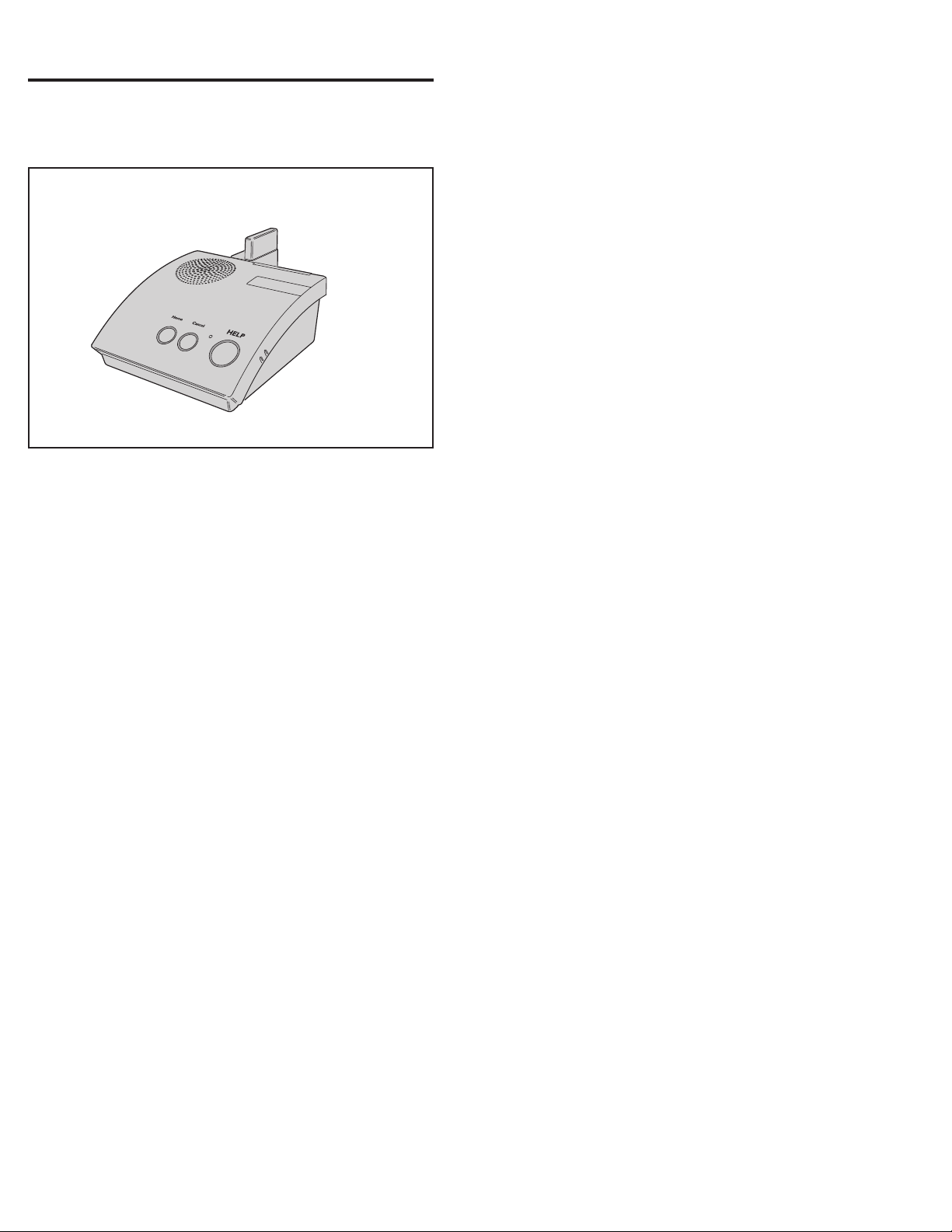
1. Product Description
The Numera PERS-4200X Console is a UL Listed supervised wireless
emergency reporting product designed for personal emergency reporting
applications. The table-top Console provides “pushbutton” emergency
assistance to anyone who desires additional security and peace of mind.
PERS-4200X Console
The Console receives signals from up to 16 wireless transmitters
(called “sensors”). Activating a transmitter causes the Console’s digital
communicator to send the appropriate alarm report to the Central Station
via a standard land-line telephone connection or through the optional
cellular wireless communications module. In addition to the Central
Station report, voice prompts sound from the Console and multi-color
indicator rings around the Console’s buttons display status.
The emergency alarm can be triggered by the HELP button on the
Console or with a wireless transmitter. The fi re alarm can be triggered
by wireless smoke detectors, and gas alerts can be triggered by wireless
carbon monoxide detectors. Wireless transmitters can also be confi gured
as activity timer reset devices to verify activity at the User’s location.
1.1 Console Features
Voice Prompts
A built-in digital voice synthesizer can speak voice prompts in English,
or Spanish to guide the user during operation, and guide the Dealer or
Installer during programming.
✓ NOTE: Check the www.nortekcontrol.com Web site for Console fi rmware
upgrades that may support additional languages.
Language specifi c Console button labels are supplied for alternate
language use. For the visually impaired, a braille label is also supplied to
identify the Console’s buttons.
Power Supply
Powered by a low voltage plug-in power supply, the Console includes
a rechargeable backup battery for operation during AC power outages.
Programming
The Console must be confi gured by the Dealer or Installer before use.
The RA4200 software confi gures the Console remotely through the
standard telephone line, or locally through the Console’s USB port, or
through the optional cellular module via the PERS Management Server.
In addition, limited programming can be done remotely through the
standard telephone line with a touch-tone telephone.
2
2. Operation Summary
A variety of transmitters can be used with the Console.
2.1 Transmitter Functions
Transmitters can be assigned to the following four functions:
Emergency
Portable, pendant, belt-clip, or wristband type transmitters are used
for personal emergency applications. When an emergency transmitter
is triggered, the Console announces the emergency alarm and an
emergency report is sent to the Central Station. The emergency alarm
can also be triggered by pressing the Console’s HELP button.
Fire
The Model 2GIG-SMKT3-345 wireless photoelectric smoke alarm
transmitter triggers the fi re alarm. When the fi re alarm is activated, the
Console announces the fi re alarm and a fi re report is sent to the Central
Station.
Carbon Monoxide (CO)
The Model 2GIG-CO3-345 wireless carbon monoxide detector transmitter
triggers the CO alarm. When a carbon monoxide alarm is activated, the
Console announces the gas alarm and a carbon monoxide report is sent
to the Central Station.
Activity
Switch or motion triggered transmitters can be used for ensuring
human activity. The 2GIG-PIR1-345 motion detector will monitor room
activity. The 2GIG-DW10-345, 2GIG-DW20R-345, and 2GIG-DW40-345
transmitters can be wired to a pushbutton or switch for manual activity
monitoring. As long as a signal is received from each activity sensor
during a programmed activity time window, an alarm will not be triggered.
15 minutes before the programmed time expires, the HOME indicator
will start blinking and the Console will announce every three minutes
that the timer will run out soon. The activity timer can be reset by the
user with a signal from one of the activity transmitters or by pressing the
HOME button on the Console. Failure to reset the activity timer within the
programmed time period will trigger the Console’s emergency alarm and
send an inactivity report to the Central Station.
2.2 Console Alarm Priorities
Alarm Priorities by Type
Each type of alarm is assigned a priority. Higher priority alarms override
lower priority alarms in the following order:
(1) Smoke alarms (on/off horn sound)
(2) Carbon monoxide alarms (on/off buzz sound)
(3) Emergency alarms (3 beeps sound)
(4) Other types of maintenance repor ts (various sounds)
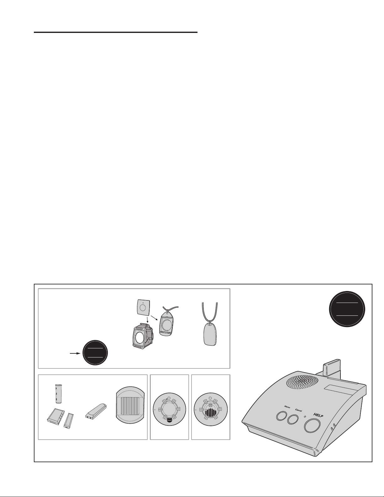
EMERGENCY TRANSMITTERS
THIS CONSOLE IS COMPATIBLE
WITH 2GIG-PHB1-345 AND
2GIG-PHB2-345 PERSONAL
HELP BUTTONS OPERATING
AT 345 MHZ
LOOK FOR
THIS LOGO
ON THE BOX
ACTIVITY TRANSMITTERS
2GIG-DW20R-345
2GIG-DW40-345
2GIG
345
MHz
2GIG-DW10-345
2GIG-PHB1-345
PENDANT OR WRISTBAND
SMOKE CARBON
2GIG-PIR1-345 2GIG-SMKT3-345
PERS-4200X Compatible Transmitters
2GIG
345
MHz
2GIG-PHB2-345
PENDANT
MONOXIDE
2GIG-CO3-345
PERS-4200X
CONSOLE
3
2.3 Console Options
Cellular Interface Module
The Model UMTS-3G/V2 Cellular Interface Module provides Two-way
over-the-air digital communications between the Console and the Central
Station. The cellular module can be used to replace the traditional
land-line telephone connection for emergency reporting.
Remote Speaker/Microphone Module
The Model RSM-MODULE Remote Speaker/Microphone Module
extends the usable range for Two-way audio communications with the
Central Station. The plug-in module and its remote speaker/microphone
unit allow the Central Station to talk and listen to the user from an
additional location in the residence/installation site that is remote from
the Console.
Alternate Console Labels
For customizing the Console, an alternate set of button identifi cation
labels are provided. The labels describe the Console’s buttons in French,
or Spanish language, or in Braille characters. Apply the label required to
the Console, above the buttons.
HOME Button Cover
For installations where the activity timer will not be used, a snap-on
button cover is supplied to hide the HOME button.
✓ NOTE: The HOME button cover cannot be easily removed once the
cover is in place.
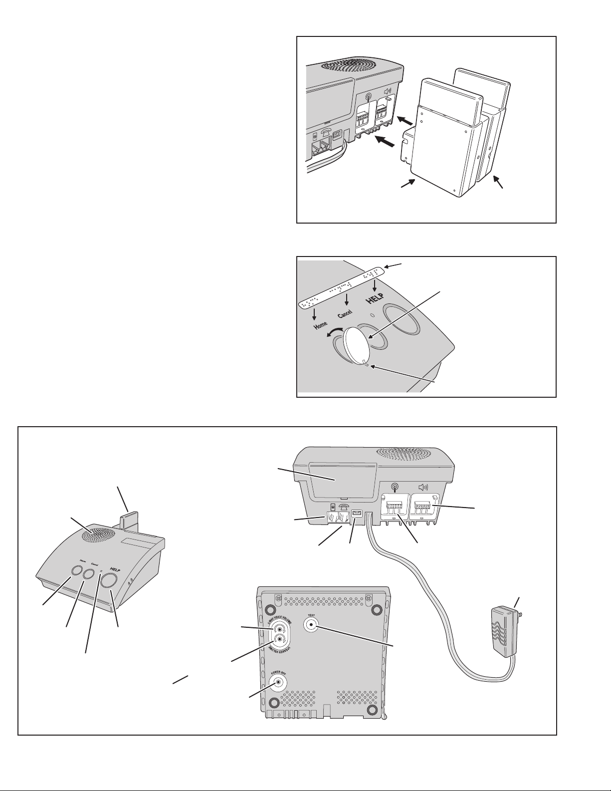
OPTION MODULES PLUG INTO CONSOLE
CELLULAR
TELEPHONE
MODULE
PERS-4200X Plug-in Option Modules
IF REQUIRED BY THE USER, APPLY BRAILLE,
FRENCH, OR SPANISH LABEL TO CONSOLE
TO HIDE THE HOME BUTTON IF THE
ACTIVITY TIMER IS NOT GOING TO BE
USED, SNAP THE HOME BUTTON
COVER INTO THE CONSOLE
TIP: INSTALL THE BUTTON COVER
BY PRESSING THE SLOT EDGE IN
FIRST, THEN SNAP THE TOP EDGE
OF THE COVER DOWN
REMOTE
SPEAKER/MICROPHONE
MODULE
OPTION
MODULE
SPEAKER
HOME
BUTTON
CANCEL
BUTTON
HELP
BUTTON
MICROPHONE
NOTE FOR UL APPLICATIONS:
SPEAKER VOLUME MUST BE
SET SO ANNOUNCEMENTS CAN
BE HEARD FROM ACROSS THE ROOM
CONSOLE
FRONT
SPEAKER
VOLUME
POWER OFF
BUTTON
2-WAY
AUDIO
VOLUME
BATTERY
DOOR
LINE IN
JACK
PHONE OUT
JACK
NOTCH IN THE BUTTON COVER LINES UP
WITH NOTCH IN THE CONSOLE CASE
Alternate Console Labels and HOME Button Cover
CONSOLE
REAR
SPEAKER / MICROPHONE
MODULE SOCKET
USB
PROGRAMMING
CELLULAR TELEPHONE
MODULE SOCKET
JACK
TEST
BUTTON
CONSOLE
BOTTOM
REMOTE
POWER
SUPPLY
4
PERS-4200X Console Component Locations
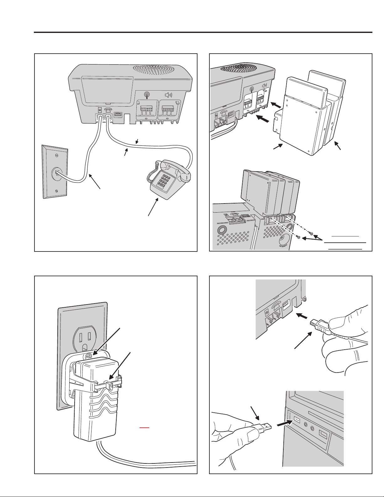
3. Console Connections
3.1 Telephone Connections 3.2 Option Module Installation
OPTION MODULES PLUG INTO CONSOLE
NOTE: THIS CONNECTION IS
OPTIONAL AND NOT REQUIRED
CELLULAR
TELEPHONE
CONNECT THE HOUSE
TELEPHONE TO THE
PHONE OUT JACK
CONNECT THE LINE IN JACK
TO THE TELEPHONE LINE
WALL JACK
MODULE
REMOTE
SPEAKER/MICROPHONE
MODULE
CAUTION!
BE SURE CONSOLE POWER
IS OFF BEFORE CONNECTING
THE OPTION MODULES
IMPORTANT INFO FOR THE USER: THE LOCAL TELEPHONE OR
ANY DEVICE CONNECTED TO THE CONSOLE'S PHONE JACK
WILL BE DISCONNECTED FROM THE TELEPHONE LINE WHILE
THE CONSOLE IS REPORTING TO THE CENTRAL STATION
3.3 Power Supply Installation 3.4 Local Programming Connection
NOTE: FOR DECORA STYLE
OUTLETS, FLIP CLAMP OVER
ATTACH POWER SUPPLY
CLAMP TO OUTLET WITH
SCREW
SECURE POWER SUPPLY
TO CLAMP WITH A ZIP-TIE
CAUTION: BE SURE THE
OUTLET HAS 24-HOUR POWER
AND IS
NOT CONTROLLED BY
A WALL SWITCH
INSERT MINI-USB PLUG
INTO JACK ON REAR OF
THE PERS-4200X CONSOLE
INSERT USB PLUG
INTO PROGRAMMING
COMPUTER USB PORT
PROGRAMMING ONLY
BE SURE TO
SECURE MODULES
WITH SCREWS!
FOR LOCAL
5

4. Console Modes & Features
The Console operates in several modes and has features that support
both the provider and the User.
4.1 Provider Modes
The Console has special modes of operation to aid the Dealer or Installer
during setup and confi guration.
Power Off Mode
Power Off Mode allows for out-of-service storage of the Console without
discharging the backup battery. The Console will arrive at the Dealer in
this mode.
Programming Mode
Programming Mode is used to setup and program the Console. It also
can be used to retrieve the unit’s event log data.
Not-Ready Mode
For a Console to report, an account number, Central Station telephone
number, and reporting format must be programmed. If these settings for
PSTN reporting or IP reporting are incomplete, the Console will indicate
Not-ready Mode.
Test/Learn Mode
Test/Learn Mode is accessible using a recessed button on the bottom
of the Console. This mode can be used to locally learn, test, or erase
multiple transmitters. While in Test/Learn Mode, all normal operations of
the Console are suspended.
For more information about these Provider Modes, see Page 8.
4.2 Provider Features
Several features of the Console are designed to aid and support the
system provider.
Event Log
The Console maintains a log of the 100 most recent system events. Each
event is tagged with the date and time the event occurred. The log can be
retrieved by the RA4200 software.
Upgradable Firmware
The PERS-4200X Console runs on internal software code called
“fi rmware”. The PERS-4200X Console uses two fi rmware resources,
system fi rmware and vocabulary fi rmware. Firmware code stays stored
in the Console’s memory and can be upgraded using the RA4200
application when fi rmware updates become available.
The Device Firmware Upgrade utility (DfuSe) (included in the RA4200
application) can upgrade a Console and the optional UMTS-3G/V2
cellular module.
Volume Controls
Two volume controls are provided to customize the sound levels of the
Console for the installation. The Dealer or Installer should use their
judgment and expertise in determining the appropriate volume level for
its users and should counsel users regarding the risks of altering the
recommended volume. The Console is designed such that the volume
cannot be set to completely eliminate the audio.
Auto Supervision
Any of the Console’s 16 sensor locations can be set to automatically
detect status supervision signals from transmitters. This feature makes
adding or replacing transmitters in fi eld units easier.
Variable Supervision Time
The Console can be set to delay reporting missing transmitter status
supervision signals until 12 or 24 hours, or 3, 7, 14, or 30 days. (Smoke
and CO detectors are always set at 24 hours per UL.)
Transmitter Low Battery Double-Check
The Console can be programmed to report a sensor low battery after
the fi rst or second time a low battery signal is received from the sensor.
Received Signal Strength (RSS) Test
To assist in setup and troubleshooting, when a transmitter is activated
while the Console is in Test Mode, the Console will measure and
announce the received signal strength (RSS) of the transmitter.
Remote Transmitter Enrolling
To make fi eld transmitter replacement easy, the transmitter’s ID code can
be remotely enrolled into the Console. The transmitter will be ready to
operate with the Console without having to “learn” the transmitter in.
✲ IMPORTANT! Test the system after remotely enrolling transmitters.
Selectable Emergency Siren
The emergency siren can be programmed for audible or silent to support
different applications. (The smoke and CO siren are always active per UL.)
Selectable Trouble Annunciation
The annunciation for Console and sensor low battery or supervisory
trouble can be audible or silent. (Trouble annunciation must be set to
audible per UL).
6
Selectable AC Power & Phone Line Fail Annunciation
The annunciation for AC power failure and telephone line failure can be
audible or silent. Audible annunciation can be set for only once, or once
every hour.

4.3 User Modes
The Console features three modes of operation for the user. Each mode
changes the way the Console reacts or annunciates, depending on
where the user is, or what time it is. Since these modes of operation are
the basis for how the Console functions, the Dealer and Installer should
review and understand these modes thoroughly.
Home Mode
Home Mode is the standard mode of operation for the Console when the
user is at home during the day. The Console will annunciate and report
all alarms as programmed.
The HOME button lights green when the Console is in Home Mode.
Away Mode
Away Mode is for when the user is going to be off site, away from the
Console. Portable emergency transmitter status reports are not monitored
while the Console is in Away Mode. Activity monitoring is suspended
during Away Mode. Console supervisory faults are always reported, but
not annunciated, in Away Mode.
Pressing the HOME button for fi ve seconds with switch the Console
between Home Mode and Away Mode.
Night Mode
Night Mode is an option that will suspend all Console supervisory
annunciations during a selected time period. This mode allows the user to
sleep without interruptions from the Console about most non-emergency
conditions. Activity monitoring messages can be used during Night Mode,
but are normally not scheduled during that time. Console supervisory
faults are always reported, but not annunciated, in Night Mode.
During the programmed time for Night Mode, pressing the HOME button
for fi ve seconds with switch the Console between Night Mode and Away
Mode.
Emergency Reporting in any User Mode
In any of the three user modes, the Console is ready to report an
emergency. Emergency signals can be received from wireless sensors
or can be triggered from the Console’s HELP button. The alarms are
announced locally by type (emergency, fi re, or carbon monoxide alarm)
through the Console’s speaker and are reported to Central Station.
The Console will sound the alarm for fi ve minutes or until the report to
the Central Station is complete (Console emergency siren is optional
through programming).
As the alarm is being reported, the Console will announce:
0 “Emergency call being placed”
If the connection to the Central Station is unsuccessful, the Console will
repeat the announcement once during each 4-minute waiting period
between call sets. Once the alarm is reported or all retry sequences
have been exhausted, the Console will stop the annunciations and return
indicators to normal.
If Two-way audio is enabled, after the report is completed the Console
will announce:
0 “Emergency reported... Please stand by”
The Console will start the Two-way audio session (if enabled).
If Two-way audio is not enabled, after the report is completed the Console
will announce:
0 “Emergency reported”
4.4 User Features
Several features of the Console are designed to aid the system user.
Since these features explain the different ways the user interacts with the
Console, the Dealer and Installer should review and understand these
features thoroughly.
Activity Timer
The activity timer is a feature that requires the User to press a button or
activate a transmitter during one or two preset time windows to prevent
an inactivity alarm from being reported.
The HOME indicator will blink during the activity timer window. When
15 minutes remain on the activity timer the Console will announce to the
User that the activity timer is running out. The User must press the HOME
button or trigger an activity transmitter to respond to the activity timer
before it runs out, or an inactivity report will be sent.
Switching the Console’s mode between Home or Night Mode and Away
Mode will also reset the activity timer.
Smoke & CO Detection
For increased protection, wireless smoke and carbon monoxide detectors
can be programmed into the Console and report these conditions to
the Central Station. Smoke and CO sensors sound different Console
announcements and send unique reporting codes.
Speakerphone Mode
The Console can be programmed to act as a hands-free speakerphone
for incoming calls. If the user forgets to hang up, a timer will automatically
disconnect the call.
The speakerphone mode can only be used on incoming calls and will
not function when the Console is operating from backup battery power.
Attempting to answer while the Console is on backup power will
cause an emergency alarm.
✓ NOTE: If the Console communication is only through an IP connection
to the Central Station and it is not connected to a PSTN or MFVN
telephone line, this feature will not function
Remote User Two-way Audio
Using a 4-digit password, the Console can be called from any telephone
and the caller can talk and listen to the user through the Console’s
two-way hands-free speakerphone either in voice-activated mode or
manual switching mode.
✓ NOTE: If the Console was confi gured with the “Answer Phone” option
NOT selected, this feature will not function.
✓ NOTE: If the Console communication is only through an IP connection
to the Central Station and it is not connected to a PSTN or MFVN
telephone line, this feature will not function.
Console Status Alert
The system continuously monitors the microprocessor that runs the
Console’s fi rmware code. If the microprocessor ever stops executing
the fi rmware code, the Console will indicate the trouble condition by
sounding a steady tone from the speaker. The tone will continue until the
condition is corrected.
7

5. Using the Provider Modes
The Console features special modes of operation to aid the Dealer or
Installer during setup and confi guration.
5.1 Power Off Mode
Power Off Mode allows for out-of-service storage of the Console without
discharging the backup battery. The Console is shipped from the factory
in this mode.
To place the Console in Power Off Mode from any other mode, remove
AC power, then press and hold the POWER OFF button on the bottom of
the Console for three seconds.
The next time AC power is applied, the Console will enter the programmed
operating mode.
UNPLUG THE POWER SUPPLY
1
PRESS THE POWER OFF BUTTON ON THE
2
CONSOLE BOTTOM FOR 3 SECONDS
THE CONSOLE WILL ANNOUNCE POWER OFF
3
AND THE INDICATORS WILL TURN OFF
"CONSOLE POWER OFF"
5.2 Not-Ready Mode
For a Console to report, an account number, Central Station telephone
number, and reporting format must be programmed. If any of these
settings are incomplete, the Console will indicate Not-ready Mode.
If the Console assumes Not-ready Mode when AC power is applied, a
1-second beep will sound (and annunciate, if programmed) and the three
indicators will blink green, orange, orange.
5.3 Programming Mode
Programming Mode is used to setup and program the Console. It also
can be used to retrieve the unit’s event log data.
Programming Mode can be accessed with RA4200 software on a PC
locally through a direct USB connection, remotely through a telephone
connection, remotely through cellular connection (if the optional
UMTS-3G/V2 cellular module in installed), or with limited access through
a telephone connection using just a touch-tone telephone.
✓ NOTE: During AC power loss, local and remote programming with
the RA4200 software is disabled unless the connection was already
established at the time of power loss.
When the Console is in Programming Mode, the three indicators will blink
green, orange, red.
Programming Mode will exit automatically after 3 minutes of inactivity, or
by pressing the CANCEL button.
While in Programming Mode, the Console is not operational and
cannot receive or report alarms.
5.4 Test/Learn Mode
Test/Learn Mode is accessible using the TEST button on the Console.
This mode can be used to locally learn, test, or erase transmitters.
To assist in setup and troubleshooting, when a transmitter is activated
while the Console is in Test Mode, the Console will measure and
announce the received signal strength (RSS) of the transmitter.
Enter Test/Learn Mode by pressing the recessed TEST button on the
bottom of the Console. Test/Learn Mode will exit automatically after
3 minutes of inactivity, or by pressing the CANCEL button.
When the Console is in Test Mode, the CANCEL indicator will slowly
blink orange.
While in Test/Learn Mode, the Console is not operational and cannot
receive or report alarms.
✓ NOTE: Transmitters can also be learned one at a time using the CANCEL
button (see Section 13.1).
IF THE CONSOLE DOES NOT HAVE AN
ACCOUNT NUMBER, CENTRAL STATION
TELEPHONE NUMBER (OR IP REPORTING
ADDRESS), OR REPORTING FORMAT
PROGRAMMED, THE CONSOLE WILL
INDICATE THAT IT IS NOT READY
CONSOLE WILL ANNOUNCE
WHEN POWERED ON
WHILE THE CONSOLE IS IN
PROGRAMMING MODE, ALL THREE
INDICATORS WILL BLINK
GREEN
ORANGE
RED
PRESS AND RELEASE THE TEST BUTTON
1
THE CONSOLE WILL ANNOUNCE TEST MODE,
2
THEN THE FIRMWARE AND HARDWARE VERSIONS
ACTIVATE ALL SYSTEM SENSORS, THE CONSOLE
3
WILL ANNOUNCE SENSOR TYPE, ZONE, AND SIGNAL
STRENGTH
Power Off Mode
PLEASE CONFIGURE BEFORE USE"
ALL THREE
INDICATORS
WILL BLINK
GREEN
ORANGE
Not-Ready Mode
LOCAL
PROGRAMMING
CONNECTION
NOTE: THE SAME INDICATIONS
OCCUR WHEN REMOTELY PROGRAMMING
Programming Mode
"TEST MODE... FIRMWARE VERSION x.x...
HARDWARE VERSION x.x"
"EMERGENCY SENSOR... ZONE ONE...
FULL SIGNAL"
CANCEL
INDICATOR
WILL BLINK ORANGE
Test/Learn Mode
"CONSOLE NOT READY...
ORANGE
USB CABLE
PROGRAMMING
PC
8
6. Programming with RA4200
The Dealer or Installer will use the RA4200 software to confi gure the
PERS-4200X Console remotely or locally.
6.1 Software Description
The RA4200 software described in this manual supports the programming
the Model PERS-4200X Personal Emergency Reporting System. The
software runs on an IBM PC or compatible computer.
What is the RA4200 Remote Access Software?
The RA4200 Remote Access software is communications software that
programs all features of PERS-4200X Consoles. It sets the options for:
Console alarm, audio, and sensors; communicator telephone numbers,
call routing, formats, reporting codes, account numbers, and more. The
RA4200 can also display the Console’s event log.
The RA4200 software has a help fi le that can be accessed at any time
by selecting “Contents” from the “Help” menu or by pressing the F1 key.
6.2 System Requirements
• IBM compatible personal computer with 2 GB RAM
• Windows XP, Windows Vista, or Windows 7 operating system
✓ NOTE: Windows 64-bit operating systems may require “Windows XP
Mode” download from Microsoft for “Panel Firmware Update (Dfuse)”
to run properly. See http://www.microsoft.com/windows/virtual-pc/
download.aspx
• VGA monitor
• For remote telephone connection, a ITU v.22bis standard 2400 baud Modem
• For local connection, an available computer USB 2.0 port and a Type A to
mini Type B USB cable.
• An Internet connection
• Hard disk drive with 50 MB available space for the software plus 18KB
available space for each account template fi le
6.2 RA4200 FAQ
How does RA4200 connect to a Console?
RA4200 can connect to the Console two ways:
• Remote connection over the telephone line using the computer’s modem.
• Local USB connection using a USB cable and the computer’s USB port.
Once the connection is made, the Console will check if its remote access
password matches the calling software’s password. If the passwords
match, access is granted.
Do I have to be connected to a Console to make programming changes?
Since Remote Access knows the Console’s programming structure, you,
the Dealer or Installer, can modify an account template without being
connected to a Console. This means that you can set all of the values
for a specifi c Console confi guration and then connect to a unit and send
all of the values that you have set. This is referred to as off-line Console
confi guration.
How do I change Console settings while on-line?
While on-line with the Console, make any changes to the account
template then send the data to change the Console.
Can I make a template with the typical settings for all of my accounts?
Programming “templates” can be created to speed up programming
multiple Consoles and minimize the potential for errors. Common
settings, such as the Central Station telephone number, communicator
format, Console and communicator confi gurations which are shared by
all of your accounts can be stored in a generic account template. That
template fi le can then be used as a basis for creating multiple customer
account template fi les that can be customized with unique customer
contact information and system options tailored for each User.
RA4200 Programming Software
9

7. Programming Outline
Use the following programming outline to guide you through the steps
required to set up the RA4200 software and program a PERS-4200X
Console. Many of the programming options available in the RA4200
program can be left in their default settings, and do not need to be
changed for most installations.
8. RA4200 Software Installation
The RA4200 remote access software is available on the Web at this link:
www.nortekcontrol.com/downloads.php
The installation program will create a directory on your hard disk drive.
Be sure that you have at least 50 megabytes free on the hard disk for the
program and any account template fi les that you create.
7.1 Setup RA4200 Software
• Install the software on your computer (Section 8).
• Test your computer’s modem (if used) (Section 9).
• Start the RA4200 program (Section 10).
7.2 Customize an Account Template
• Open a new or existing account template (Section 11).
• Enter customer information (Section 11.2).
• Set the Console’s password and operational options (Section 11.3).
• Enter any wireless sensor ID codes for sensors that won’t be learned locally
(Section 11.4).
• Select the Console’s communication method and options for PSTN and/or IP
reporting (Section 11.5).
• Choose the general communicator reporting options and assign any custom
reporting codes (Section 11.6).
7.3 Program the Console
• Connect to the Console (Section 12.2).
• Set the Console’s time and date (Section 12.3).
• Send the account template data to the Console (Section 12.3).
✲ IMPORTANT! AFTER ANY PROGRAMMING CHANGES ARE MADE TO
A CONSOLE, PERFORM THOROUGH TESTING TO VERIFY THAT THE
CONSOLE OPERATES AS INTENDED.
8.1 To Install the Remote Access Program:
1. Download the RA4200 programming software installation package
from the Web site at the link shown above.
2. Extract the RA4200Setup.ZIP fi le to expand the fi les.
3. Browse to fi nd the SETUP.EXE fi le. Double-click on SETUP.EXE and
the installation program will start.
4. Click the Next button to install the Remote Access software. Follow
the on-screen instructions as the setup program creates the directory
and copies the program fi les onto your hard disk. The setup program
will also install a virtual COM port driver to support a USB connection.
If desired, select the check box to place a RA4200 Remote Access
icon your desktop.
✓ NOTE: If RA4200 already is on your system and you are performing a
reinstallation, or an update, you will be prompted to modify, remove, or
repair the RA4200 software.
8.2 To Remove the Remote Access Program:
1. Press START, SETTINGS, CONTROL PANEL. Double-click on
ADD/REMOVE PROGRAMS.
2. Select RA4200 and click ADD/REMOVE or CHANGE/REMOVE
button depending on your Windows Operating system.
✓ NOTE: Alternately, you can select UNINSTALL from the RA4200 folder
on the start menu.
10
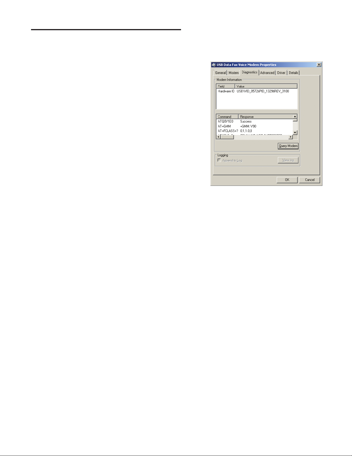
9. Testing the Modem
A modem is used when connecting to a Console remotely, over the
telephone line. A modem is not required for local programming with a
USB cable.
When using a modem, be sure that the computer is running correctly
and that the modem is installed and working properly before you run the
RA4200 Remote Access Program.
Use the following steps to test the modem and determine the computer’s
COM port number that it is connected to.
9.1 To Test the Modem in Windows
Windows Control Panel can be used to test the modem and determine
what COM port the modem is connected to.
1. Open Windows Control Panel.
2. Select PHONE AND MODEM.
3. Click on the MODEMS tab. The modem and the COM port used
should be shown.
4. Note the COM port number. It’s used when setting COM port in the
RA4200 Send/Receive window (see Section 12.1).
5. Click PROPERTIES and select the DIAGNOSTICS tab.
6. Click QUERY MODEM. If the modem is connected and working
properly, the Modem Information window will display detailed
Command and Response modem information. If the modem is not
working properly, Windows will notify you.
Windows Modem Test
11

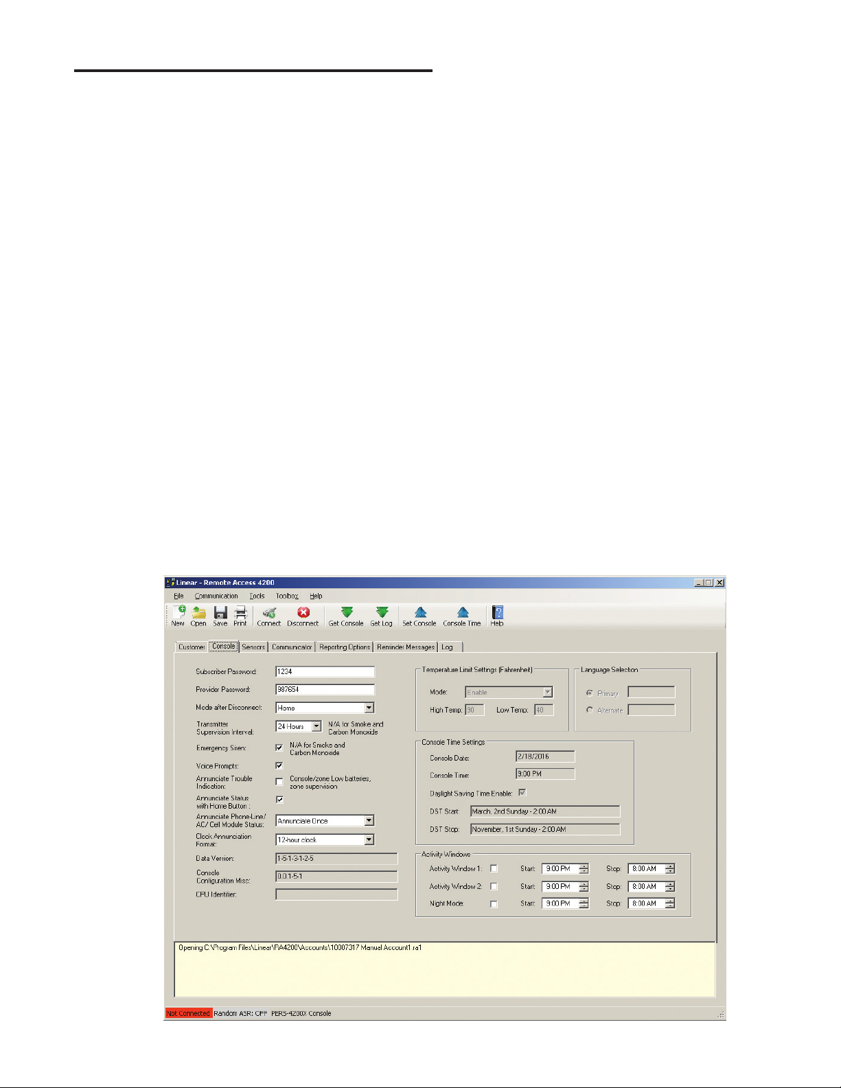
10. RA4200 Software Overview
The RA4200 software is a Windows compatible program with menus and
tabs to select various account fi elds to make selections and enter data.
10.1 Starting the Program
To Run the Program:
Double-click on the RA4200 desktop icon.
The RA4200 program will launch, displaying the menu bar and icons, the
Account Template with its seven tabs, a communications status window,
and a connection status indicator at the bottom.
10.2 The Account Template Tabs
Seven tabs are available for the Account Template. Each tab displays
major areas for programming and administrating a PERS-4200X Console
installation.
The Account Template tabs function as follows:
Customer
Displays fi ll-in fi elds for details of the User’s information for the
specifi c PERS-4200X installation. Fields include name, address,
telephone numbers, customer ID#, and a large fi eld for special
notes regarding the User to be fi lled in by the Dealer or Installer.
Console
Displays fi ll-in fi elds for setting information and options for the
specifi c PERS-4200X Console. General settings such as passwords,
siren enable, voice prompts, voice language, activity timer and Night
Mode time windows can be set. Several other Console options and
settings are also available in this tab. The Console’s time and date
settings are displayed.
Sensors
Displays the 16 wireless sensor zones of the PERS-4200X Console.
Each sensor zone displays its sensor ID number, sensor type,
supervision option, two-way audio option, and the current sensor
battery and supervision status.
Communicator
Displays Console connection options for public switched telephone
network (PSTN) and internet protocol (IP) reporting. Typical PSTN
settings are for the communicator’s Central Station telephone
numbers, account number, reporting format, audible dialing tones,
and dialing format. Typical IP settings are for Central Station IP
address and port numbers, IP account number, IP reporting format,
Management Server IP address and port numbers.
Reporting Options
Displays reporting options for the Console. Options for AC failure
reporting, supervisory event reporting, mode switch reporting,
automatic answer, automatic status report interval, speakerphone
timer, two-way audio mode, dialing delay, and 4x2 reporting codes.
Log
Displays the event log of the PERS-4200X Console. After the log
is retrieved from the Console by the Dealer, this tab will show the
system events with a time and date stamp in the order that they
occurred.
CONNECTION STATUS
INDICATOR
ACCOUNT TEMPLATE TABS
COMMUNICATIONS
STATUS WINDOW
RA4200 Customer Tab
12
 Loading...