


RE-2
RE-2
Residential Telephone
Entry System
With Built-in Wireless Receiver
(760) 438-7000
USA & Canada (800) 421-1587 & (800) 392-0123
Toll Free FAX (800) 468-1340
www.linearcorp.com
Installation,
Programming,
and Operation Instructions

CONTENTS FEATURES
• TWO-WAY SPEAKERPHONE
• CALL WAITING
• CALL FORWARDING
• DISTINCTIVE RINGS FOR ACCESS CALLS
• SEVEN ACCESS TIME ZONES
• TIMED “DO NOT DISTURB” PRIVACY FEATURE
• DIGITALLY SYNTHESIZED VOICE PROMPTS
• RESIDENCE CONTROL OF RELAYS
• PROGRAMMABLE RELAY CONTROL PREFIXES
• 100 ENTRY CODE CAPACITY
• 1-6 DIGIT ENTRY CODE LENGTH
• EACH ENTRY CODE CAN BE PROGRAMMED TO
ACTIVATE EITHER OR BOTH RELAYS
• 100 TRANSMITTER CAPACITY
• SUPPORTS 4 BLOCKS OF TRANSMITTERS WITH 24
FACILITY CODES
• UP TO FOUR ACCESS GROUPS FOR SHARED
CONTROL OF TRANSMITTER BLOCKS
• SUPPORTS MGT SAFETY EDGE TRANSMITTER
• INTERNAL CLOCK AND CALENDAR WITH BATTERY
BACKUP (GREATER THAN 10 YEAR BATTERY LIFE)
• EVENT LOG MEMORY RETAINS THE LAST 450
SYSTEM EVENTS
• KEYPAD PROGRAMMABLE
• LOCALLY & REMOTELY PROGRAMMABLE WITH A
TELEPHONE OR COMPUTER
• PROGRAMMING SOFTWARE BUILT-IN, CONNECT
WITH ANY INTERNET BROWSER
• WEATHER-PROOF, TAMPER-RESISTANT HOUSING
• SUPERHETERODYNE RADIO RECEIVER
• REMOTE KEYPAD SUPPORT
• BRIGHT WHITE LED DOWNLIGHT
• 2 HEAVY DUTY FORM “C” (N.O. & N.C) RELAY
OUTPUTS
• TIMED ANTI-PASSBACK
• KEYPAD LOCKOUT
• TACTILE KEY FEEL
• TWO DOOR SENSE/INHIBIT INPUTS
• TWO OPEN REQUEST INPUTS
• ACCESS KEYSWITCH PROVISION
• REMOVABLE TERMINAL BLOCKS
• OPTIONAL COLOR CCTV CAMERA
PRODUCT DESCRIPTION . . . . . . . . . . . . . . . . . . . . . . . . . .1
INSTALLATION INFORMATION . . . . . . . . . . . . . . . . . . . . 2
COMPONENT LOCATIONS . . . . . . . . . . . . . . . . . . . . . . . . 3
WIRING DIAGRAM . . . . . . . . . . . . . . . . . . . . . . . . . . . . . . 4
ENTRY SYSTEM MOUNTING . . . . . . . . . . . . . . . . . . . . . . 5
TELEPHONE WIRING . . . . . . . . . . . . . . . . . . . . . . . . . . . 6
TELEPHONE WIRING OPTIONS . . . . . . . . . . . . . . . . . . . . 6
MULTIPLE UNIT INSTALLATIONS . . . . . . . . . . . . . . . . . . 7
CONTROL WIRING . . . . . . . . . . . . . . . . . . . . . . . . . . . . . 8
POWER, BATTERY, & GROUND WIRING . . . . . . . . . . . . . . 9
OPTIONAL REMOTE ANTENNA . . . . . . . . . . . . . . . . . . . . 9
OPTIONAL REMOTE KEYPAD . . . . . . . . . . . . . . . . . . . . .10
OPTIONAL KEYSWITCH . . . . . . . . . . . . . . . . . . . . . . . . .10
OPTIONAL COLOR CCTV CAMERA . . . . . . . . . . . . . . . . . . 11
PROGRAMMING ACCESS . . . . . . . . . . . . . . . . . . . . . . . . .12
PROGRAMMING REFERENCE . . . . . . . . . . . . . . . . . . . . .15
BASIC SYSTEM PROGRAMMING . . . . . . . . . . . . . . . . . . .16
ENTRY CODE PROGRAMMING . . . . . . . . . . . . . . . . . . . . .16
TRANSMITTER PROGRAMMING . . . . . . . . . . . . . . . . . . .17
TELEPHONE PROGRAMMING . . . . . . . . . . . . . . . . . . . . . 17
ADVANCED SYSTEM PROGRAMMING . . . . . . . . . . . . . . .18
SYSTEM ADJUSTMENTS . . . . . . . . . . . . . . . . . . . . . . . 20
RE-2 OPERATION . . . . . . . . . . . . . . . . . . . . . . . . . . . . . .21
RESIDENT PROGRAMMING QUICK REFERENCE . . . . . . 22
SPECIFICATIONS . . . . . . . . . . . . . . . . . . . . . . . . . . . . . 23
DIMENSION DRAWING . . . . . . . . . . . . . . . . . . . . . . . . . 23
TROUBLESHOOTING . . . . . . . . . . . . . . . . . . . . . . . . . . . 23
PROGRAMMING WORKSHEET . . . . . . . . . . . . . . . . . . . . 24
LINEAR LIMITED WARRANTY . . . . . . . . . . . . . . . . . . . . 26

1
PRODUCT DESCRIPTION
Linear’s RE-2 Telephone Entry System is designed for residential
or light commercial access control applications. The speakerphone,
keypad, radio receiver, and optional video camera are housed in a
rugged enclosure that can be mounted to a pedestal, bolted directly
to a wall, or mounted recessed in a wall with the optional trim ring.
The die-cast keypad keys have bright, easy-to-read graphics and
are lit with overhead lights. The two operation buttons; CALL and
HELP, are machined for heavy-duty reliability.
Operation
Arriving visitors will approach the unit and place a call to the
residence by pressing the CALL button. The RE-2 will acquire the
residence’s local telephone line and generate distinctive rings to the
house telephones. The resident, knowing that the distinctive ring is
originating from the access area, can answer any house telephone
and converse with the visitor. If the resident decides to grant access
to the visitor, they can activate either output relay in the RE-2 by
pressing a key on the telephone’s keypad. If the resident decides
not to grant access, hanging up or pressing a key will disconnect
the visitor’s call.
Call Waiting
If the resident is using the telephone at the time a visitor calls, the
RE-2 will sound beeps on the telephone line to announce that a
visitor is calling. The resident can press a key on the telephone to
place the outside caller on hold and communicate with the visitor.
After granting or denying access to the visitor, the outside caller will
be re-connected to the resident.
Call Forwarding
Programmable call forwarding allows the RE-2 to dial any selected
telephone number when a visitor presses the CALL button. For
example, with call forwarding enabled, the RE-2 could dial a cell
phone to contact the resident while outside or away from the
residence. The resident will be able to communicate with the visitor
and grant or deny access from the remote telephone.
Alternate Numbers
For installations where multiple residences exist inside the same
controlled opening (such as a guest house or granny fl at) three
alternate calling numbers can be programmed. The alternate
numbers can be called by entering a short code at the keypad.
Local Control
The resident can issue control commands from the local telephones
without a call from a visitor. By dialing a specifi c series of digits, the
resident can control either of the two relays. The resident an also
initiate voice communications with the entry system.
Access Methods
Up to 100 entry codes, from 1 to 6 digits in length, can be
programmed. Each entry code can activate either, or both, of the
relay outputs. Linear’s Model AM-KP keypad can be used as a
secondary remote keypad for the RE-2.
Up to 24 sets of block coded MegaCode
®
transmitters (up to
100 transmitters total) can be used to gain access through the
RE-2’s built-in radio receiver. Each transmitter can be individually
suspended or re-activated. One facility code can be programmed
to identify each block of transmitters. Programming of individual
(non-block coded) transmitters is limited to 24 transmitters by
entering one transmitter per block.
System Features
Time Zones
The RE-2 contains an internal clock and calendar. Seven
programmable “time zones” allow setting time periods to schedule
system functions. Each time zone can be active or inactive on certain
days. Keypad entry codes, wireless transmitters, automatic access
control, call forwarding, and the “Do Not Disturb” feature can each
be set to only be active during a specifi c time zone period. Up to ten
“holiday” days can be programmed. Each of the seven time zones
can be set to be active or inactive during a holiday.
Portal Supervision
The SENSE/INHIBIT input can be used two ways. If programmed
for “door sense”, a switch on the door detects forced entry or door
ajar situations. If programmed for “inhibit”, the input can be wired to
a “service” switch or automatic timer that will disable the Relay #1
when required.
Hardwired Activation
The OPEN REQUEST input can be wired to an exit loop detector
or exit photo beam to allow automatic exit activation. An emergency
access keyswitch can be mounted in the RE-2 case to allow keyed
entry for authorized personnel.
Access Security
The “anti-passback” feature allows the option of preventing the use of
the same code or the same transmitter again before the programmed
time elapses. The “keypad lockout” feature discourages tampering
by disabling the keypad for three minutes after a programmable
number of incorrect entry codes has been entered at the keypad.
Event Log
An access log of up to 450 events is stored in the unit’s memory.
System activity is logged as it occurs with the date and time of the
event. The access log data can be retrieved locally or remotely with
a computer through the RE-2’s built-in modem.
Local & Remote Programming
The system’s built-in programming software can be accessed on-site
or off-site using a computer with any Internet browser. The software’s
graphic display of each of the programming step makes programming
easy. Without a computer, the RE-2 can be programmed with its
main keypad, from any local telephone connected to the same line,
or by calling from any remote telephone.
The EEPROM memory retains all entry codes, transmitter
information, and programming, even without power.
Obstacle Detection
Linear’s Model MGT safety edge transmitter is compatible with the
RE-2 This MGT detects and transmits obstacle events to the RE-2
receiver. Obstacle signals from an MGT transmitter will activate
Relay #2.
Alarm Interface
Relay #2 can be programmed for alarm shunt to bypass an alarm
loop during entry, or alarm trigger to cause an alarm during forced
entry. Five other activation options are available for Relay #2.
Voice Synthesizer
A built-in voice synthesizer sounds voice prompts through the
speaker, local and remote telephones.
2
INSTALLATION INFORMATION
Before beginning installation, please review the entire instructions
and become familiar with the system’s operation, wiring, and
programmable options.
System Location
For pedestrian door or gate installations, mount the Entry System
on a rigid wall near the controlled door. Avoid mounting the unit
in a location where regular mechanical shock will occur due to a
slamming door or spring loaded pedestrian gate.
For vehicular gate installations, mount the Entry System in clear
view of the gate, but far enough from the gate so the user cannot
touch the gate from the keypad.
★ WARNING FOR ALL GATE INSTALLATIONS: TO AVOID
SERIOUS INJURY OR DEATH, MAKE SURE THAT THE
UNIT IS FAR ENOUGH FROM THE GATE SO THAT THE
USER CANNOT TOUCH THE GATE WHILE OPERATING
THE KEYPAD. HOWEVER, FOR SAFETY, THE GATE
MUST BE FULLY VISIBLE FROM THE KEYPAD.
Telephone Wires
The quality of the system’s audio communications is related to the
type of telephone wire and its installation. Noise and hum can be
introduced into the telephone wires. Use only high-quality telephone
wire rated for direct underground burial. All telephone wire should
be twisted-pair.
• Minimum size of 24 AWG for up to 800 feet.
• Minimum size of 22 AWG for up to 1600 feet.
• Minimum size of 20 AWG for up to 2200 feet.
• Minimum size of 18 AWG for up to 3600 feet.
DO NOT ROUTE TELEPHONE AND AC WIRING INSIDE THE
SAME CONDUIT. Route all telephone wires inside a dedicated
conduit that is at least six inches away from any AC line wiring.
Power Supply
Use the supplied 16-volt 20-VA transformer to power the RE-2.
DO NOT POWER ANY OTHER EQUIPMENT FROM THE SAME
TRANSFORMER, use a separate power supply. Keep the system
power wires as short as practical to reduce the chance of noise and
hum pickup.
• For low voltage power wire runs up to 100 feet, use 18 AWG, THHN
600-volt insulated wire.
• For low voltage power wire runs up to 200 feet, use 16 AWG, THHN
600-volt insulated wire.
• Use 22 AWG or larger (depending on the load) for all other
connections.
ALWAYS REMOVE POWER PRIOR TO SERVICING
Earth Ground
To avoid damage to the unit from static discharges, connect the
RE-2’s EARTH GROUND and case ground terminals to a good
earth grounding point within 10 feet. The case ground terminal is
the #8 screw located on the lower right corner of the rear case.
Also, the RE-2’s Telephone Bypass Module must be grounded to
provide surge protection for the telephone line. Suggested wiring
size is 12 AWG for earth ground.
Removable Terminal Blocks
For convenience, the RE-2 is provided with removable terminal
blocks. It is important that these blocks be removed evenly in order
to avoid causing permanent damage to them.
1. Be certain power is off before removing or installing the terminal
blocks.
2. Squeeze the terminal block sides between your thumb and index
fi nger.
3. Rock the terminal block left and right while gently pulling it out.
4. When re-installing the terminal blocks, press the block in straight and
evenly.
✦ NOTE: Unscrew the terminal screws several turns before inserting
wires.
3
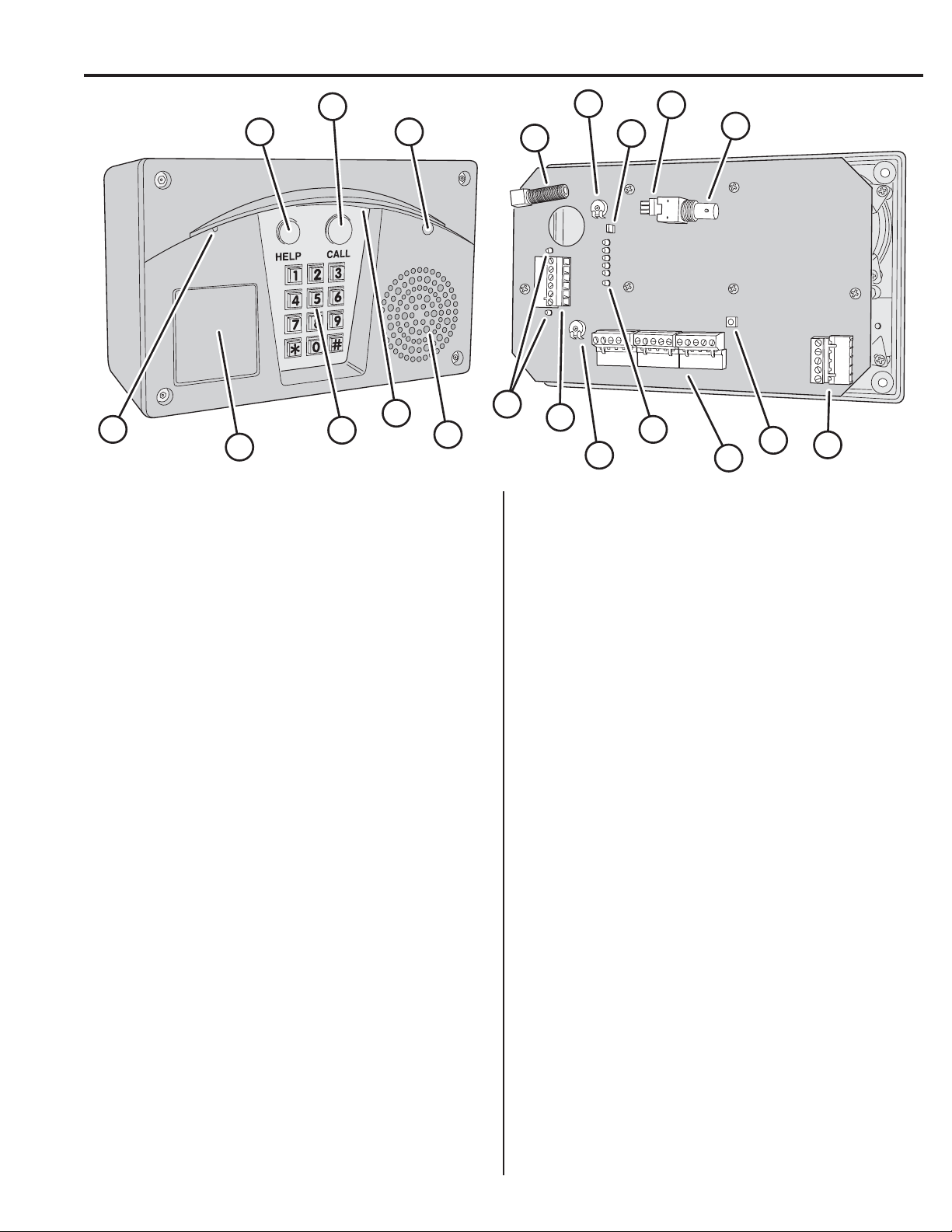
11 MAIN TERMINAL BLOCK
For power, backup battery, sense inputs, open request inputs, and
remote keypad connections.
12 STATUS INDICATORS
Six indicators light to display system power, radio, and modem
status.
13 SPEAKERPHONE VOLUME CONTROL
Controls the audio level produced by the speaker during
communications between the visitor and the resident.
14 RELAY TERMINAL BLOCK
For Relay #1 and Relay #2 output connections to the access control
devices.
15 RELAY INDICATORS
Indicators for Relay #1 and Relay #2 will light when the relay is
activated.
16 SPEAKER
Weatherproof speaker for system operation and programming.
17 DOWNLIGHT
Illuminates keypad and visitor operation buttons. The light operates
dusk to dawn and adjusts its time depending on the system’s
geographic location.
18 KEYPAD
Die-cast metal 12-key keypad with tactile action. For system
programming and keying in entry codes.
19 OPTIONAL KEYLOCK
Location for mounting access keylock.
20 MICROPHONE
The high-sensitivity microphone monitors sound at the keypad area
for the entry system’s speakerphone.
1 HELP BUTTON
Pressing this button causes the system to play the help message to
instruct the visitor on system use.
2 CALL BUTTON
Pressing this button causes the system to call the residence
telephones with a distinctive ring signal.
3 OPTIONAL COLOR CCTV CAMERA
Location for the optional Model CCM-2 color CCTV camera. The
camera views the keypad area.
4 ANTENNA CONNECTOR
For connection to a Model EXA-1000 or EXA-2000 remote
antenna.
5 DIGITAL SPEECH VOLUME CONTROL
Controls the audio level of the voice synthesizer. This adjustment
effects the audio level of the voice synthesizer and system tone from
the speaker.
6 LINE MONITOR JUMPER
For testing and troubleshooting. Remove jumper to listen to
telephone line audio through the speaker.
7 CAMERA CONNECTOR
Provides power and video connection for the optional Model CCM-2
CCTV camera.
8 VIDEO OUT CONNECTOR
For cable connection to a video monitor. (Optional Model CCM-2
CCTV camera required).
9 TELEPHONE TERMINAL BLOCK
For telephone line and earth ground connections.
10 RESTART BUTTON
Pressing this button restarts the system. This button DOES NOT
erase any programming data.
1
2
3
4
5
6
7
8
9
10
11
12
13
14
15
16
17
18
19
20
COMPONENT LOCATIONS
4
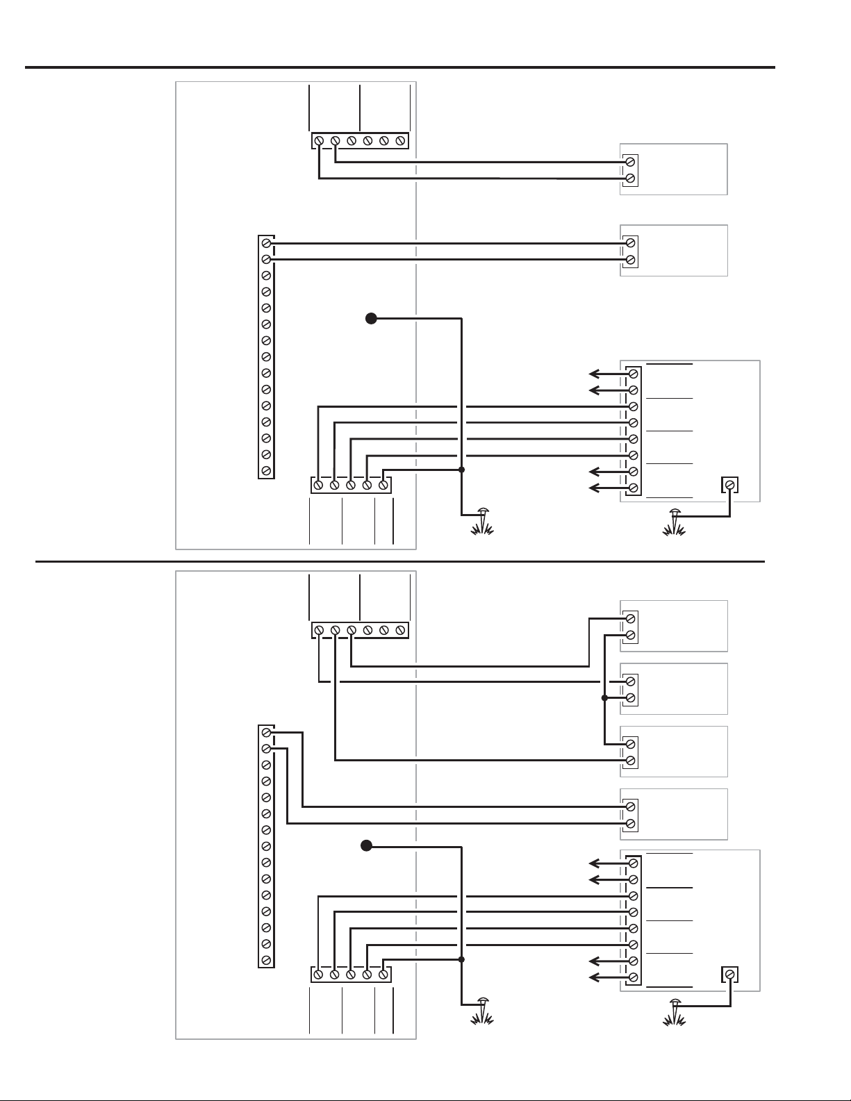
WIRING DIAGRAM
GATE
OPERATOR
OPEN
16 VAC
20 VA
TRANSFORMER
TELCO
OPEN #1
KEYPAD GND
KEYPAD DAT 1
KEYPAD DAT 0
KEYPAD PWR
TRANSFORMER
TRANSFORMER
BATTERY NEG
BATTERY POS
SENSE #1
COMMON
KEYPAD CLK
KEYPAD DVAL
OPEN #2
RELAY
#1
RE-2
TELEPHONE ENTRY
SYSTEM
SENSE #2
TYPICAL
GATE INSTALLATION
WIRING
GROUND
STAKE
N.O.
COM
N.C.
N.O.
COM
N.C.
RELAY
#2
RING
TIP
RING
TIP
EARTH
HOUSE
TIP
RING
TIP
RING
TIP
RING
TIP
RING
TELCO
RE-2
TELCO
RE-2
HOUSE
HOUSE
TELEPHONE
BYPASS
MODULE
EARTH
GROUND
TO HOUSE
PHONES
TO TELCO
LINE
TYPICAL
DOOR INSTALLATION
WIRING
NOTE: DO NOT POWER
THE LOCKING DEVICE FROM
THE RE-2 TRANSFORMER
ELECTRIC
DOOR STRIKE
MAGNETIC
DOOR LOCK
ACCESS
DEVICE
POWER
SUPPLY
NOTE: A MAGNETIC LOCK AND
DOOR STRIKE ARE BOTH SHOWN,
TYPICALLY ONLY ONE IS USED
16 VAC
20 VA
TRANSFORMER
TELCO
OPEN #1
KEYPAD GND
KEYPAD DAT 1
KEYPAD DAT 0
KEYPAD PWR
TRANSFORMER
TRANSFORMER
BATTERY NEG
BATTERY POS
SENSE #1
COMMON
KEYPAD CLK
KEYPAD DVAL
OPEN #2
RELAY
#1
RE-2
TELEPHONE ENTRY
SYSTEM
SENSE #2
N.O.
COM
N.C.
N.O.
COM
N.C.
RELAY
#2
RING
TIP
RING
TIP
EARTH
HOUSE
TIP
RING
TIP
RING
TIP
RING
TIP
RING
TELCO
RE-2
TELCO
RE-2
HOUSE
HOUSE
TELEPHONE
BYPASS
MODULE
EARTH
GROUND
TO HOUSE
PHONES
TO TELCO
LINE
RELAY RATING:
3 AMPS AT
30 VOLTS AC OR DC
MAXIMUM
RELAY RATING:
3 AMPS AT
30 VOLTS AC OR DC
MAXIMUM
10' MAXIMUM
WIRE RUN
GROUND
STAKE
10' MAXIMUM
WIRE RUN
GROUND
STAKE
10' MAXIMUM
WIRE RUN
GROUND
STAKE
10' MAXIMUM
WIRE RUN
CASE
GROUND
CASE
GROUND
5
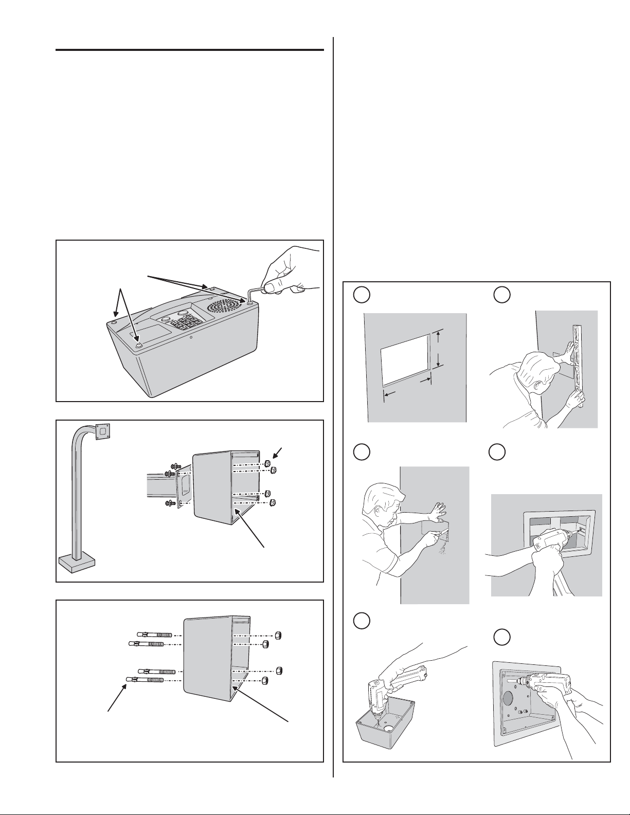
ENTRY SYSTEM MOUNTING
Pedestal Mounting
The RE-2 Entry System can be mounted with the Model GNC-1
(curb mount) or Model GNB-1 (burial mount) gooseneck pedestals.
1. Open the RE-2 case by removing the four security screws with the
wrench provided (see Figure 1).
2. Use four security bolts and locking nuts to secure the backplate to the
pedestal (see Figure 2).
Wall Mounting
The RE-2 Entry System can be mounted directly to a wall or fl at
surface.
1. Open the RE-2 case by removing the four security screws with the
wrench provided (see Figure 1).
2. Use the appropriate fasteners to secure the system’s backplate to the
mounting surface. When mounting the system to a concrete wall, use
concrete wedge anchors (see Figure 3).
Recessed Mounting
The RE-2 can be mounted recessed using an accessory trim-ring.
The trim-ring mounts in the wall and the cabinet attaches to the
trim-ring.
Two trim-rings models are available to match the color of the RE-2
case:
• For the RE-2N use trim-ring P/N ACP00915.
• For the RE-2SS use trim-ring P/N ACP00917.
1. Identify the location of any studs in the wall.
2. Cut a 10-1/4” wide by 6-1/4” high rectangular hole between studs at
the mounting location.
3. Install any additional mounting material required to provide surfaces
inside the wall for attaching the trim-ring.
4. Place the trim-ring in the wall hole. Check for level, then attach the
trim-ring with screws into the side tabs.
5. Drill the cabinet’s four self-drill mounting holes the appropriate size for
the hardware.
6. Attach the cabinet to the trim-ring using self-tapping screws.
7. Route the wiring into the cabinet.
Figure 3. Wall Mounting
Figure 2. Pedestal Mounting
REMOVE THE FOUR
SECURITY SCREWS
TO OPEN THE CASE
Figure 1. Opening the RE-2 Case
PEDESTAL
MOUNTING
MOUNT REAR CASE
WITH SECURITY BOLTS
AND LOCKNUTS
PEDESTAL
CAUTION!
BE SURE THE MOUNTING HARDWARE
DOES NOT EXTEND MORE THAN 1"
INSIDE THE REAR COVER OR
ELECTRICAL DAMAGE MAY OCCUR
USE WEDGE ANCHORS
FOR CONCRETE OR
OTHER APPROPRIATE
ANCHORS FOR DIFFERENT
MATERIALS
WALL
MOUNTING
CAUTION!
BE SURE THE MOUNTING HARDWARE
DOES NOT EXTEND MORE THAN 1"
INSIDE THE REAR CASE OR
ELECTRICAL DAMAGE MAY OCCUR
10-1/4"
6-1/4"
MARK HOLE LOCATION
4
INSTALL ANY SPACER
SHIMS TO ALLOW MOUNTING
ATTACH THE TRIM-RING
WITH SCREWS
5
6
DRILL 3/16" HOLES IN
THE CABINET AT THE
PRE-MARKED LOCATIONS
ATTACH THE CABINET TO
THE TRIM-RING WITH
SELF-TAPING SCREWS
DETERMINE LOCATION FOR
THE 10-1/4" x 6-1/4" MOUNTING HOLE
3
CUT MOUNTING HOLE
1 2
RECESSED
MOUNTING
Figure 4. Recessed Mounting
6
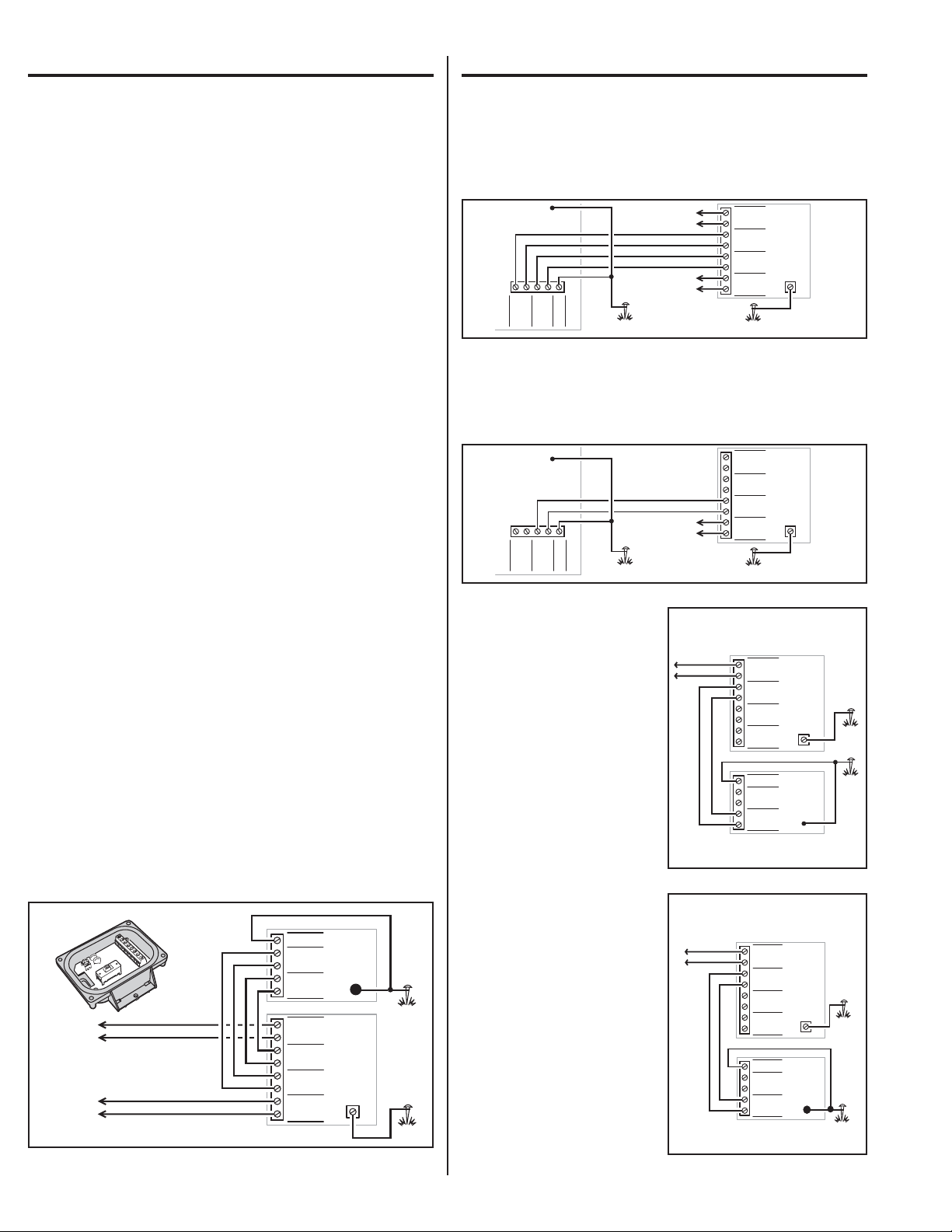
TELEPHONE WIRING
The RE-2 connects between the incoming telephone line of the
residence and local telephone sets.
Telephone Bypass Module
The RE-2’s Telephone Bypass Module provides a switch to remove
the RE-2 from the telephone line and re-connect the local telephones
to the telephone system. ALL TELEPHONE WIRING FOR THE
RE-2 MUST PASS THROUGH THE BYPASS MODULE.
The bypass module is housed in a weather-resistant enclosure and
should be located in an area that is easily accessible to the resident.
In case of system trouble, the resident can use the bypass switch to
remove the RE-2 from the telephone system.
Telephone Wiring
• DO NOT ROUTE TELEPHONE AND AC WIRING INSIDE THE SAME
CONDUIT. Route all telephone wires inside a dedicated conduit that is
at least six inches away from any AC line wiring.
• All telephone wiring must be made on the “house” side of the telephone
company’s demarcation device (the terminal block where the telephone
line connects to the residence).
• If any security system or personal alert system at the residence is
connected to the telephone line, be sure that it is connected to the line
ahead of the Telephone Bypass Module using a RJ-31X or RJ-38X
interface.
• Use only high-quality telephone wire rated for direct underground
burial. All telephone wire should be twisted-pair with a minimum size of
24 AWG.
Typical Telephone Wiring
1. Connect the bypass module’s EARTH GROUND terminal to a good
earth ground.
2. Before connecting the incoming telephone line to the bypass module
check the polarity of the wires with a DC voltmeter. Connect the
negative wire (RING - usually green) to the bypass module TELCO
RING terminal. Connect the positive wire (TIP - usually red) to the
bypass module TELCO TIP terminal.
3. Connect the resident’s local telephone line RING (usually green) to
the bypass module HOUSE RING. Connect the local telephone line
TIP (usually red) to the bypass module HOUSE TIP terminal.
4. Connect the RE-2 TELCO RING to the bypass module RE-2 TELCO
RING terminal. Connect the RE-2 TELCO TIP to the bypass module
RE-2 TELCO TIP terminal.
5. Connect the RE-2 HOUSE RING to the bypass module RE-2 HOUSE
RING terminal. Connect the RE-2 HOUSE TIP to the bypass module
RE-2 HOUSE TIP terminal.
TELEPHONE WIRING OPTIONS
Shared Line
This is the standard confi guration. The telephone line is routed
through the RE-2 to the house phones. Pressing the Call button on
the RE-2 will cause the RE-2 to disconnect the house phones from
the telephone company line and generate a ring signal that is heard
on the house phones.
Dedicated Line
Pressing the Call button on the RE-2 will cause the RE-2 to sieze
the phone line and dial out to an outside number. See PPN #54 for
programming options.
Intercom Mode
Pressing the Call button on
the RE-2 will cause the RE-2
to generate a ring signal as
if it were an intercom station.
A live phone line is not used
and the RE-2 provides power
for the remote intercom phone.
See PPN #52 for programming
options.
✦ Note: in this mode, remote
programming, call forwarding
or alternate resident calling is
not available.
Ring Down Mode
Pressing the Call button
on the RE-2 will cause the
RE-2 to sieze the phone
line and provide immediate
communications with the PBX
system. See PPN #54 for
programming options.
TELCO
RING
TIP
RING
TIP
EARTH
HOUSE
TIP
RING
TIP
RING
TIP
RING
TIP
RING
TELCO
RE-2
TELCO
RE-2
HOUSE
HOUSE
TELEPHONE
BYPASS
MODULE
EARTH
GROUND
FROM
TELEPHONE
COMPANY
GROUND
STAKE
10' MAXIMUM
WIRE RUN
GROUND
STAKE
10' MAXIMUM
WIRE RUN
RE-2
ENTRY
SYSTEM
CASE
GROUND
GROUND
STAKE
TIP
RING
TIP
RING
TIP
RING
TIP
RING
TELCO
RE-2
TELCO
RE-2
HOUSE
HOUSE
TELCO
RING
TIP
RING
TIP
EARTH
HOUSE
TELEPHONE
BYPASS
MODULE
EARTH
GROUND
TO HOUSE
INTERCOM
TELEPHONES
RE-2
ENTRY
SYSTEM
CASE
GROUND
GROUND
STAKE
TO
PBX
SYSTEM
GROUND
STAKE
GROUND
STAKE
TIP
RING
TIP
RING
TIP
RING
TIP
RING
TELCO
RE-2
TELCO
RE-2
HOUSE
HOUSE
TELEPHONE
BYPASS
MODULE
EARTH
GROUND
TELCO
RING
TIP
RING
TIP
EARTH
HOUSE
RE-2
ENTRY
SYSTEM
CASE
GROUND
TELCO
RING
TIP
RING
TIP
EARTH
HOUSE
TIP
RING
TIP
RING
TIP
RING
TIP
RING
TELCO
RE-2
TELCO
RE-2
HOUSE
HOUSE
TELEPHONE
BYPASS
MODULE
EARTH
GROUND
TO HOUSE
PHONES
TO TELCO
LINE
GROUND
STAKE
10' MAXIMUM
WIRE RUN
GROUND
STAKE
10' MAXIMUM
WIRE RUN
RE-2
ENTRY
SYSTEM
CASE
GROUND
Figure 7. Dedicated Line Wiring
Figure 6. Shared Line Wiring
Figure 8. Intercom Mode Wiring
Figure 9. Ring Down Mode Wiring
Figure 5. Telephone Wiring
GROUND
STAKE
TIP
RING
TIP
RING
TIP
RING
TIP
RING
TELCO
RE-2
TELCO
RE-2
HOUSE
HOUSE
TELCO
RING
TIP
RING
TIP
EARTH
HOUSE
TELEPHONE
BYPASS
MODULE
EARTH
GROUND
TO HOUSE
PHONES
TO TELCO
LINE
RE-2
ENTRY
SYSTEM
TELEPHONE
BYPASS
MODULE
CASE
GROUND
GROUND
STAKE
7
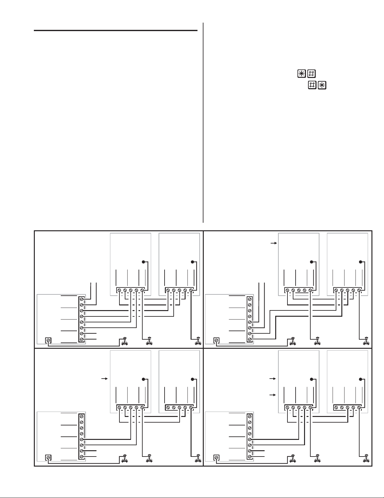
MULTIPLE UNIT INSTALLATIONS
Any of the four basic operation modes (Shared Line, Dedicated Line,
Intercom, and Ring Down) may be used with multiple RE-2s. The
telephone line wiring is “daisy chained” (the telephone line routes
through one unit to the next) as shown below. Always connect the
telephone line + to TIP, and - to RING.
The Telephone Bypass Module only performs the bypass function
in the Shared Line Mode, but it will provide extra electrical surge
protection in all modes. A surge on the TELCO terminals will be
suppressed through the EARTH GROUND terminal. Always use
separate AC transformers to power each RE-2.
When multiple units are connected together, only two units can be
controlled by resident telephone commands, and only one unit
can be programmed to answer the telephone (PPN #33) for remote
telephone commands. Remote programming via computer is not
supported when using multiple RE-2s.
Command Prefi x for Multiple Units
Programming and relay control may be through the individual RE-2
keypads or through the house telephone(s) when using the Shared
Line or Intercom Modes. To support using the house telephone(s)
to issue commands, each RE-2 must be programmed to a different
“command prefi x” (PPN #72).
• Set one unit’s command prefi x to
• Set the other unit’s command prefi x to
In the case of simultaneous visitors at different units when using
the Shared Line Mode, putting one RE-2 “on hold” to communicate
with the second RE-2, then returning to the fi rst RE-2 is not
recommended. Instead, fi nish all communications with the fi rst RE-2
before servicing the second RE-2. Simultaneous visitors at multiple
units used on a single line wired in the Ring Down Mode will cause
a “conference call” effect between units
Figure 10. Multiple Unit Wiring
TIP
RING
TIP
RING
TIP
RING
TIP
RING
TELCO
RE-2
TELCO
RE-2
HOUSE
HOUSE
TELEPHONE
BYPASS
MODULE
EARTH
GROUND
GROUND
STAKE
FIRST
RE-2
ENTRY
SYSTEM
TELCO
RING
TIP
RING
TIP
EARTH
HOUSE
CASE
GROUND
LAST
RE-2
ENTRY
SYSTEM
TELCO
RING
TIP
RING
TIP
EARTH
HOUSE
CASE
GROUND
FROM
TELEPHONE
COMPANY
TO
HOUSE
TELEPHONES
GROUND
STAKE
GROUND
STAKE
TIP
RING
TIP
RING
TIP
RING
TIP
RING
TELCO
RE-2
TELCO
RE-2
HOUSE
HOUSE
TELEPHONE
BYPASS
MODULE
EARTH
GROUND
GROUND
STAKE
FIRST
RE-2
ENTRY
SYSTEM
TELCO
RING
TIP
RING
TIP
EARTH
HOUSE
CASE
GROUND
LAST
RE-2
ENTRY
SYSTEM
TELCO
RING
TIP
RING
TIP
EARTH
HOUSE
CASE
GROUND
TO
INTERCOM
TELEPHONES
GROUND
STAKE
GROUND
STAKE
SHARED LINE
MODE
INTERCOM
MODE
DEDICATED LINE
MODE
RING DOWN
MODE
PROGRAM THIS
RE-2 UNIT ONLY FOR
"INTERCOM MODE"
(PPN #52)
DO NOT CONNECT
TO A LIVE TELEPHONE LINE
TIP
RING
TIP
RING
TIP
RING
TIP
RING
TELCO
RE-2
TELCO
RE-2
HOUSE
HOUSE
TELEPHONE
BYPASS
MODULE
EARTH
GROUND
GROUND
STAKE
FIRST
RE-2
ENTRY
SYSTEM
TELCO
RING
TIP
RING
TIP
EARTH
HOUSE
CASE
GROUND
LAST
RE-2
ENTRY
SYSTEM
TELCO
RING
TIP
RING
TIP
EARTH
HOUSE
CASE
GROUND
FROM
TELEPHONE
COMPANY
OR PBX
GROUND
STAKE
GROUND
STAKE
PROGRAM ALL
RE-2 UNITS FOR
"CALL FORWARDING"
(PPN #54)
TIP
RING
TIP
RING
TIP
RING
TIP
RING
TELCO
RE-2
TELCO
RE-2
HOUSE
HOUSE
TELEPHONE
BYPASS
MODULE
EARTH
GROUND
GROUND
STAKE
FIRST
RE-2
ENTRY
SYSTEM
TELCO
RING
TIP
RING
TIP
EARTH
HOUSE
CASE
GROUND
LAST
RE-2
ENTRY
SYSTEM
TELCO
RING
TIP
RING
TIP
EARTH
HOUSE
CASE
GROUND
FROM
PBX
GROUND
STAKE
GROUND
STAKE
PROGRAM ALL
RE-2 UNITS FOR
"RING DOWN MODE"
(PPN #54)
IF DESIRED, CHANGE
RESIDENT RESPONSE KEYS
(PPN #71)
 Loading...