


AM3Plus
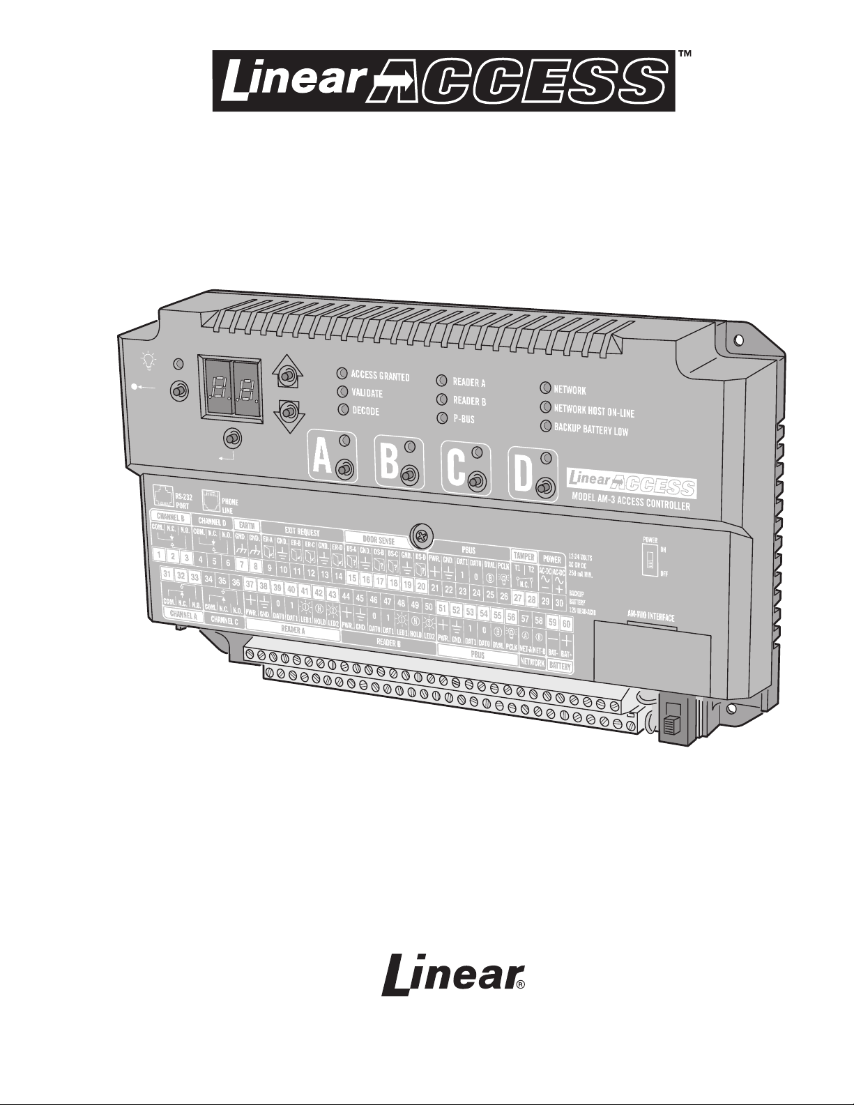
AM3Plus
Access Controller
Installation Instructions
USA & Canada (800) 421-1587 & (800) 392-0123
(760) 438-7000 • FAX (760) 438-7043
Toll Free FAX (800) 468-1340
www.linearcorp.com

Contents Introduction
Introduction . . . . . . . . . . . . . . . . . . . . . . . . . . . . . . . . . . . . . 2
Operation . . . . . . . . . . . . . . . . . . . . . . . . . . . . . . . . . . . . . . . 2
Programming and Cardholder Maintenance . . . . . . . . . . . . . . 2
Hardware Features . . . . . . . . . . . . . . . . . . . . . . . . . . . . . . . . 3
Software Highlights . . . . . . . . . . . . . . . . . . . . . . . . . . . . . . . 3
Feature Overview . . . . . . . . . . . . . . . . . . . . . . . . . . . . . . . . . 3
Accessory Overview . . . . . . . . . . . . . . . . . . . . . . . . . . . . . . . 4
PBUS Accessories . . . . . . . . . . . . . . . . . . . . . . . . . . . . . . . . . 4
Wiegand Accessories . . . . . . . . . . . . . . . . . . . . . . . . . . . . . . 4
Component Locations . . . . . . . . . . . . . . . . . . . . . . . . . . . . . . 5
Wiring Diagram . . . . . . . . . . . . . . . . . . . . . . . . . . . . . . . . . . . 6
Important Mounting Requirements . . . . . . . . . . . . . . . . . . . . 7
AM3Plus Mounting . . . . . . . . . . . . . . . . . . . . . . . . . . . . . . . . 8
Relay Output Wiring . . . . . . . . . . . . . . . . . . . . . . . . . . . . . . . 9
Power, Battery, & Ground Wiring . . . . . . . . . . . . . . . . . . . . . 10
Telephone Wiring . . . . . . . . . . . . . . . . . . . . . . . . . . . . . . . . .11
PBUS Accessories . . . . . . . . . . . . . . . . . . . . . . . . . . . . . . . . .11
Wiegand Accessories . . . . . . . . . . . . . . . . . . . . . . . . . . . . . .12
RS-232 Port . . . . . . . . . . . . . . . . . . . . . . . . . . . . . . . . . . . . .12
Optional Network Connections . . . . . . . . . . . . . . . . . . . . . . .13
System Controls . . . . . . . . . . . . . . . . . . . . . . . . . . . . . . . . . 16
System Diagnostics . . . . . . . . . . . . . . . . . . . . . . . . . . . . . . .17
Specifi cations . . . . . . . . . . . . . . . . . . . . . . . . . . . . . . . . . . . 18
Troubleshooting . . . . . . . . . . . . . . . . . . . . . . . . . . . . . . . . . 18
Linear Limited Warranty . . . . . . . . . . . . . . . . . . . . . . . . . . . 19
FCC Notice . . . . . . . . . . . . . . . . . . . . . . . . . . . . . . . . . . . . . 19
The AM3Plus Access Controller is designed for use as a primary access
control device for gated communities, parking garages, offi ce buildings,
apartments, dormitories, hotels/motels, commercial buildings and
recreational facilities.
Housed in a lockable, plastic enclosure, the AM3Plus features a 2-digit
LED display, nine status indicators, four relay indicators with four relay
activation pushbuttons. Three programming buttons, a reset button,
and a power indicator are present. The enclosure is monitored with a
magnetic “tamper” switch.
The system controls its four output relays by responding to various input
devices that react to proximity cards, transmitters, and entry codes. The
four relay output channels can be programmed to control electric door
strikes, magnetic locks, door & gate operators, or barrier gates.
Access is granted or denied depending on the current user’s authorization
to gain access and system settings that control groups of users or all
users. Complete access control event logging, access time restriction,
access location restriction, and administration functions are also available
to manage the installation.
The AM3Plus is network ready. Multiple units can be interconnected
on a 3-wire RS-485 network or through modems. The AM3Plus can be
used in mixed networks with its sister products, the AE1000Plus and
AE2000Plus.
Two sets of Wiegand inputs are available for connection to 26, 30, or
31-bit Wiegand devices (card readers, etc.). Two sets of PBUS inputs are
available for connection to Linear’s line of remote accessories.
The AM3Plus can be powered from a 12-24 Volt AC or DC source. DC
power can be obtained from the access device or AC power from a
separate power transformer. The system supports and charges a 12-volt
backup battery for operation during power outage. Low battery detection
circuitry monitors the backup battery’s condition. The EEPROM memory
retains all entry codes and programming, even without power.
Throughout this manual, multiple-unit networks are referenced. Depending on
the programming method used, networks can contain the following model units:
NETWORK MODEL OPTIONS
With AccessBase2000 Programming With AXNET Programming
AM3Plus AM3Plus
AE1000Plus AE1000Plus
AE2000Plus AE2000Plus
AM-3
AE-1000
AE-2000
2
Operation
In a typical installation, the unit’s memory would be programmed with
each resident’s name and entry code number. Arriving visitors would use
a remote keypad to enter their entry code. Also proximity receivers, swipe
card readers, and other remote devices can be used with the system.
Block coded MegaCode® transmitters can be used to gain access
through a remote radio receiver connected to the AM3Plus PBUS. Each
transmitter can be individually suspended or re-activated.
The system’s clock/calendar can control access based on specifi c times
and dates. Automatic relay activation can be scheduled. Access can be
restricted to certain times and dates. Holiday access can be scheduled.
The system’s event log records system activity for future reference.
Programming and Cardholder Maintenance
Two programming methods can be used with the system: Linear’s
AXNET or AccessBase2000. Each has its advantages, but only one must
be chosen at the onset for each installation. Once a unit is programmed
with one method, all programming data will be lost if a decision is made
to switch to the other method.
Linear’s AXNET software is built into each unit. It allows connecting to the
unit using common browser software from any PC at any location. Each
unit’s database is stored in the unit’s memory.
Linear’s AccessBase2000 software installs in one dedicated PC and is
designed with many extra features usually for large network installations.
The database for the entire system is stored in the dedicated PC.

Hardware Features
✓ FOUR FORM “C” (N.O. & N.C) RELAYS
Each relay has 3-amp @ 24-volt rating with a status indicator and relay latching pushbutton
✓ FOUR REQUEST-TO-EXIT INPUTS
Activates access device for exiting using a hardwired switch
✓ FOUR SENSING INPUTS
For sensing door position to control door-ajar and alarm features, or for access inhibit timer
✓ NINE STATUS INDICATORS
Display access, reader, and system information
✓ OPTIONAL MODEM
Compatible with the Model ACM-1 plug-in modem for telephone communications with system
✓ RS-232 COMMUNICATIONS PORT
RS-232 port for direct connection to printer or computer
✓ NETWORK SUPPORT
Multiple units can be connected together to share data
✓ EXPANSION INTERFACE SUPPORT
Model AM-MIO accessory adds additional input and outputs to the AM3Plus
✓ ON-BOARD CLOCK/CALENDAR CIRCUIT
Stamps the event log data as it is stored in the system’s memory
✓ WIEGAND INPUTS
Two Wiegand format card reader inputs for connection to external devices
✓ LINEAR PBUS SUPPORT
Two PBUS input/output ports for connection to Linear accessories
✓ BACKUP BATTERY SUPPORT
Built-in backup battery charging circuit
✓ POWER FAILURE MONITOR
AC power input is monitored, power outages are recorded in the event log
Software Highlights
✓ COMPUTER PROGRAMMABLE
No dedicated programmer required, program with a computer and a modem
✓ LARGE ENTRY CODE CAPACITY
Up to 20,000 entry codes can be used for gaining access
✓ 2-8 DIGIT ENTRY CODE LENGTH
Flexible code length for different applications
✓ LARGE TRANSMITTER CAPACITY
Up to 45,600 block coded and 20,000 individually enrolled
Linear transmitters can be used for gaining access
✓ TRANSMITTER FACILITY CODE SUPPORT
Identifi es wireless transmitters by installation
✓ LARGE CARD CAPACITY
Up to 45,600 block coded and 20,000 individually enrolled cards can be used for gaining access
✓ FOUR INDEPENDENT RELAY CHANNELS
Each output’s action is programmable
✓ PROGRAMMABLE TIME SCHEDULED RELAY ACTIVATION
Activation for up to four time periods for each of the 31 system time zones
✓ PROGRAMMABLE TIME ZONE ACCESS VALIDATION
Validation during four time periods for each of the 31 system time zones
✓ PROGRAMMABLE VALIDATION DAYS
Select days of the week access is allowed
✓ PROGRAMMABLE HOLIDAY DAYS
Select up to 24 expiring & 24 non-expiring holidays for access restriction
✓ OBSTACLE TRANSMITTER SUPPORT
Compatible with Linear’s Model MGT transmitter
✓ EVENT LOG
Stores up to 20,000 system events in memory for record keeping
✓ DELETED CARDHOLDER DATABASE
System logs deleted cardholders for future identifi cation
✓ TIMED OR TRUE ANTI-PASSBACK
Options to temporarily disable a cardholder’s credentials after access for
a preset time or depending on the cardholder’s access direction
Feature Overview
Relay Outputs
Four 3-amp dry contact relay outputs are provided to activate four access
devices, such as door strikes, magnetic locks, automatic doors, barrier gates,
and automatic sliding gates. The relay outputs can also be used for alarm
contact shunting, operator obstacle triggering, and alarm activation. Each of
the four relays can also be manually activated from buttons on the front of the
AM3Plus. LED indicators display the status of each relay.
Request-to-Exit Inputs
Each relay channel has a request-to-exit input. These inputs are supplied for
hardwire activation of the access devices. Typically a request-to-exit input is
wired to a pushbutton inside of the access controlled area. When a person
desires to exit, pressing the pushbutton will activate the output relay channel
and trigger the access device. A loop detector for automatic gate operation
can be connected to a request-to-exit input.
Sensing Inputs
The sensing inputs connect to door switches that monitor whether the
controlled door is open or closed. The sensing inputs may alternately be
programmed as “access inhibit” inputs for use with an external timer or service
switch.
Optional Modem
A modular connector is provided for telephone line connection to the unit’s
optional 33.6K baud modem. The system can be accessed remotely for
programming and control over the standard telephone system using a
personal computer with a modem. For system backup, a computer connected
through the modem can store and retrieve the AM3Plus memory data.
RS-232 Communications Port
A modular connector is provided for the bi-directional 38.4K baud RS-232
port. The AM3Plus RS-232 port connects to a personal computer’s COM port.
System programming can be performed locally with a computer connected to
the RS-232 port.
Obstacle Detection
Linear’s Model MGT safety edge transmitter is compatible with the AM3Plus.
The MGT detects and transmits obstacle events to a remote receiver
connected to the AM3Plus.
Programming Memory
The AM3Plus fl ash memory retains all entry codes, transmitter information,
card access, and programming, even without power.
Battery Backup
The system supports a 12-volt battery backup for operation during power
outage. The system will charge the backup battery when AC power is
present.
Network Support
Multiple AE1000Plus, AE2000Plus, & AM3Plus units can be networked
together via three-wire RS-485 cables or through modems allowing
information sharing between the units. A common event log is retained for all
of the networked units.
Linear PBUS Ports
Two 6-wire Linear PBUS input/output ports are available to connect to
several accessories (keypads, proximity readers, remote receivers). A typical
application for a remote keypad or reader would be to control additional doors
or gates.
3
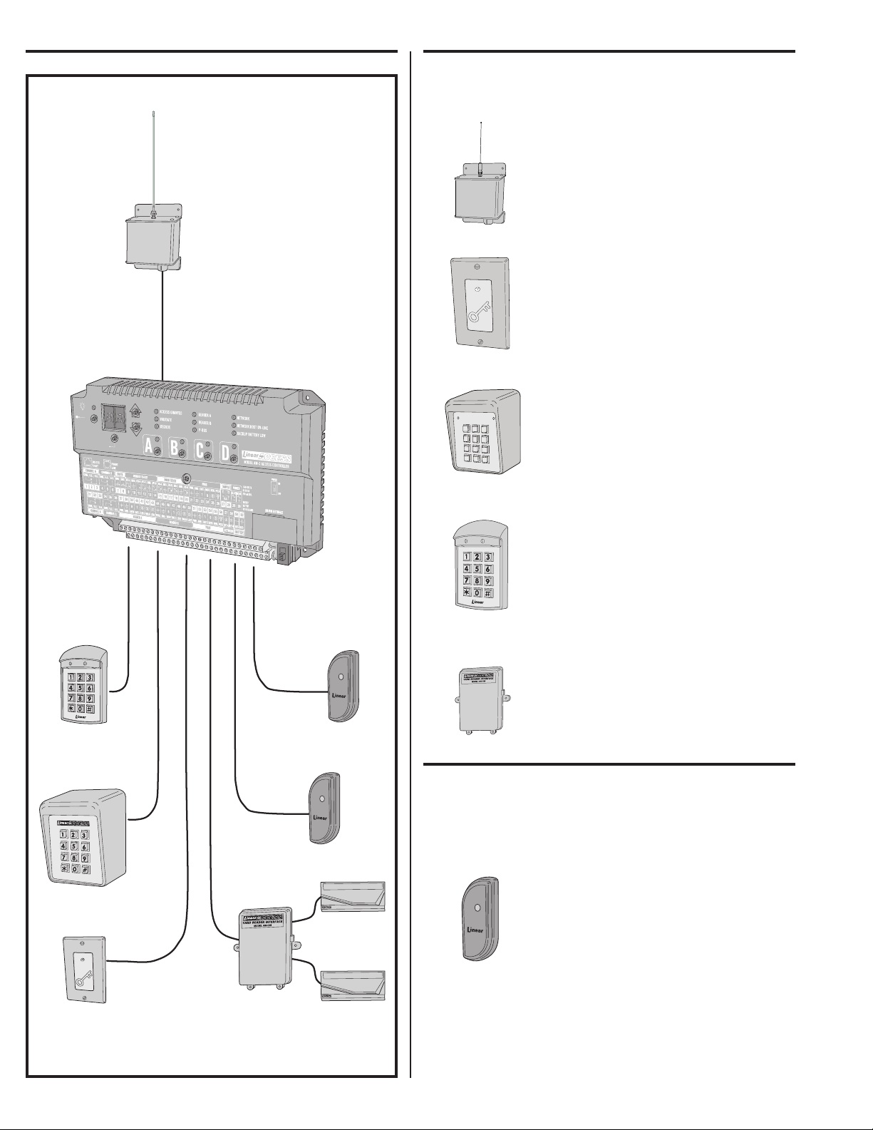
Accessory Overview PBUS Accessories
*
5
6
7
8
9
0
#
1
2
3
4
Several compatible accessories are available to connect to the two 6wire communications “PBUS” inputs. Up to six PBUS accessories can be
used with each AM3Plus unit.
AM-RRR Remote Radio Receiver
For wireless transmitters, connect the Model
AM-RRR high-gain superheterodyne UHF receiver.
The receiver is housed in a weather-resistant
enclosure and can be mounted indoors or
outdoors. Gaskets and a weather-tight wiring strain
relief seal the unit from the elements.
AM-RPR Remote Proximity Receiver
The Model AM-RPR functions as a remote device
that supplies localized radio reception for the
AM3Plus In a typical installation, the AM-RPR
would be mounted in a plastic single-gang
electrical box next to the controlled opening. When
the user requires access, their transmitter must
be activated within three inches of the AM-RPR
faceplate.
AM-KP Exterior Keypad
The Model AM-KP is housed in a rugged cast
aluminum enclosure designed for exterior
installations. The die-cast keys have bright,
easy-to-read yellow graphics. The keypad can
be mounted to a pedestal or directly to a wall.
A keylock secures the keypad to the mounting
backplate.
AM-KPI Interior Keypad
The Model AM-KPI keypad is housed in a rugged,
plastic enclosure designed to be mounted indoors
in a standard single-gang electrical box. Tamper
resistant screws secure the keypad to its mounting
plate. The die-cast keys have bright, easy-to-read
yellow graphics and is illuminated with white
LEDs. The keypad is supplied with a satin-chrome
bezel and three interchangeable colored bezels
(white, ivory, & bronze) to customize the keypad
appearance for the installation.
AM-CRI Card Reader Interface
The Model AM-CRI expands the standard two
AM3Plus Wiegand inputs by supporting one or
two additional 26-bit Wiegand input devices per
AM-CRI interfaces used.
PBUS
ASSESSORIES
AM-KPI
INTERIOR
KEYPAD
AM-RRR
REMOTE
RADIO
RECEIVER
AM3PLUS
ACCESS CONTROLLER
WIEGAND
ACCESSORIES
AM-PR
PROXIMITY
READERS
AM-RRR
AM-RPR
AM-KP
AM-KPI
AM-CRI
Wiegand Accessories
The two WIEGAND format inputs connect WIEGAND devices to the
AM3Plus. Linear offers a Wiegand format proximity reader. Most other
manufacturer’s 26, 30 & 31-bit WIEGAND output devices can also be
used with the AM3Plus.
AM-PR Proximity Reader
AM-KP
EXTERIOR
KEYPAD
AM-RPR
RADIO
PROXIMITY
RECEIVER
WIEGAND
CARD
READERS
AM-PR
AM-CRI
CARD
READER
INTERFACE
The Model AM-PR is a radio-based reader that
works with either proximity tags (Model AM-PT) or
proximity cards (Model AM-PC), both of which are
slotted to attach to key rings. Upon reading a user’s
tag or card, the reader sends the entry data via a
Wiegand output to the AM3Plus. An integral LED
confi rms to the user that access is granted.
4
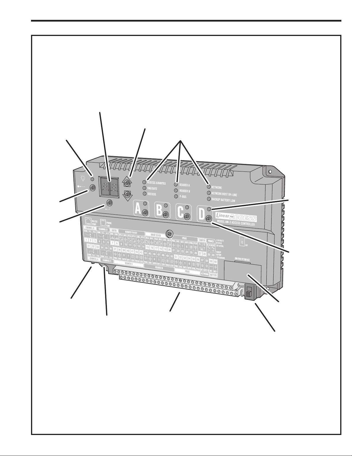
Component Locations
STATUS/PROGRAM
DISPLAY
ARROW
POWER
INDICATOR
BUTTONS
STATUS
INDICATORS
AM3PLUS
ACCESS CONTROLLER
RESET
BUTTON
ENTER
BUTTON
COM PORT
CONNECTOR
TELEPHONE LINE
CONNECTOR
RELAY
INDICATORS (4)
RELAY LATCH
BUTTONS (4)
AM-MIO INTERFACE
CONNECTOR (HIDDEN)
TERMINAL
BLOCKS
POWER
SWITCH
5
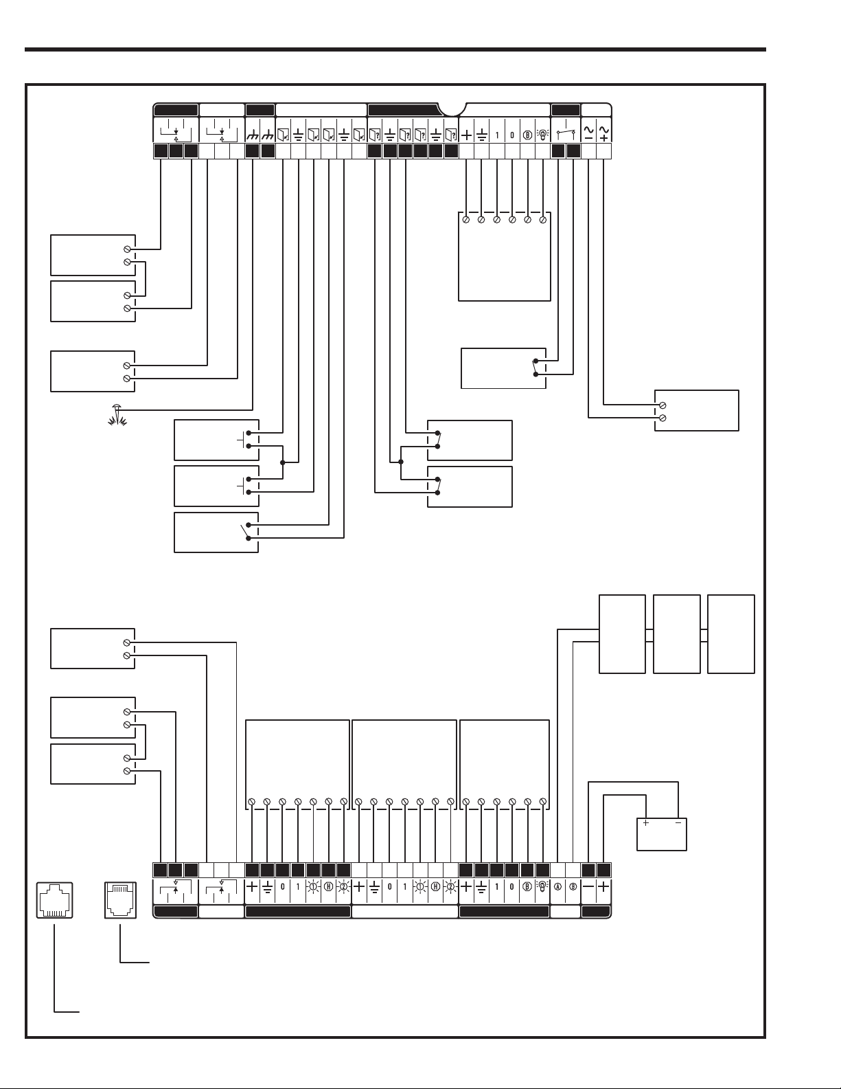
Wiring Diagram
RELAY RATING:
3 AMPS @ 30 VOLTS
AC/DC MAXIMUM
ELECTRIC
DOOR
STRIKE
DOOR
STRIKE
POWER SUPPLY
GATE
OPERATOR
OPEN
EARTH
GROUND
STAKE
CHANNEL D REQUEST-TO-EXIT PBUS POWER
4 5 6 9 1011121314 212223242526 29301 23 7 8 15 16 17 18 19 20 27 28
DOOR EXIT
REQUEST
BUTTON "A"
DOOR EXIT
REQUEST
BUTTON "B"
GATE
EXIT LOOP
SENSOR
EARTH
GND. GND.
RTE-A
GND.
RTE-B RTE-C
GND.
RTE-D
DS-A GND. DS-B DS-C GND. DS-D PWR. GND. DAT1 DAT0 DVAL PCLK T1 T2N.O.N.C.COM.N.O.N.C.COM.
DOOR SENSE
GND
PWR
UP TO SIX PBUS
DEVICES CAN BE
USED WITH EACH AM3PLUS
DOOR "B"
SENSE
CONTACT
DOOR "A"
SENSE
CONTACT
DAT1
PBUS
DEVICE
CABINET
TAMPER
SWITCH
DAT0
DVAL
TAMPERCHANNEL B
PCLK
AC-DC AC-DC
N.C.
TERMINALS 1-30
POWER INPUT
12-24 VOLTS
AC OR DC
250 mA MIN.
16 VAC
20 VA
TRANSFORMER
AM3Plus
GATE
OPERATOR
MAGNETIC
DOOR
LOCK
DOOR
LOCK
POWER SUPPLY
RS-232
PORT
OPEN
PHONE
LINE
THIS WIRING EXAMPLE SHOWS:
DOOR ACCESS WITH A DOOR STRIKE ON RELAY CHANNEL "A"
DOOR ACCESS WITH A MAGNETIC LOCK ON RELAY CHANNEL "B"
GATE ACCESS WITH A GATE OPERATOR ON RELAY CHANNEL "C"
TWO WIEGAND
DEVICES CAN BE
USED WITH EACH AM3PLUS
WIEGAND
DEVICE
LED1
DAT1
DAT0
GND
PWR
34 35 36 44 45 46 47 48 49 50 57 5831 32 33 37 38 39 40 41 42 43 51 52 53 54 55 56 59 60
PWR. GND. DAT0 DAT1 LED1 HOLD LED2 PWR. GND. DAT0 DAT1 LED1 HOLD LED2 PWR. GND. DAT1 DAT0 DVAL PCLK NET-A NET-BN.O.N.C.COM.N.O.N.C.COM. BAT- BAT+
CHANNEL A
TO DEDICATED TELEPHONE LINE
(OPTIONAL MODEL ACM-1 MODEM REQUIRED)
CHANNEL C
READER A PBUS
HOLD
LED2
UP TO SIX PBUS
DEVICES CAN BE
USED WITH EACH AM3PLUS
LED2
PWR
PBUS
DEVICE
DAT1
GND
WIEGAND
DEVICE
LED1
DAT1
DAT0
GND
PWR
READER B NETWORK
HOLD
DAT0
DVAL
PCLK
NETWORK
UNIT
REFER TO NETWORK SECTION
BATTERY
NETWORK
UNIT
MULTIPLE NETWORK UNITS
FOR WIRING OPTIONS
12 VOLT
BATTERY
TERMINALS 31-60
NETWORK
UNIT
BACKUP
BATTERY
12V LEAD-ACID
FOR LOCAL COMPUTER CONNECTION
USE LINEAR MODEL A2C
SERIAL COMPUTER CABLE
6
 Loading...