


ENGLISH
OWNER’S MANUAL
MONITOR TV
Please read this manual carefully before operating your set and retain it for future reference.
MONITOR TV MODELS
M1962D
M2062D
M2262D
M2362D
M2762D
www.lge.com

PREPARATION
FRONT PANEL CONTROLS
■ This is a simplified representation of the front panel. The image shown may be somewhat different from your set.
|
|
|
|
|
|
|
|
|
|
|
|
|
|
|
|
|
|
|
|
|
|
|
|
|
|
|
|
|
|
|
|
|
|
|
|
|
|
|
|
|
|
|
|
|
|
|
|
|
|
|
|
|
|
|
|
|
|
|
|
|
|
|
|
|
|
|
|
|
|
|
|
|
|
|
|
|
|
|
|
|
|
|
|
|
|
|
|
|
|
|
|
|
|
|
|
|
|
|
|
|
|
|
|
|
|
|
|
|
|
|
|
|
|
|
|
|
|
|
|
|
|
|
|
|
|
|
|
|
|
|
|
|
|
|
|
|
|
|
|
|
|
|
|
|
|
|
|
|
|
|
|
|
|
|
|
|
|
|
|
|
|
|
|
|
|
|
|
|
|
|
|
|
|
|
|
|
|
|
|
|
|
|
|
|
|
|
|
|
|
|
|
|
|
|
|
|
|
|
|
|
|
|
|
|
|
|
|
|
|
|
|
|
|
|
|
|
|
|
|
|
|
|
|
|
|
|
|
|
|
|
|
|
|
|
|
|
|
|
|
|
|
|
|
|
|
|
|
|
|
|
|
|
|
|
|
|
|
|
|
|
|
|
|
|
|
|
|
|
|
|
|
|
|
|
|
|
|
|
|
|
|
|
|
|
|
|
|
|
|
|
|
|
|
|
|
|
|
|
|
|
|
|
|
|
|
|
|
|
|
|
|
|
|
|
|
|
|
|
|
|
|
|
|
|
|
|
|
|
|
|
|
|
|
|
|
|
|
|
|
|
|
|
|
|
|
|
|
|
|
|
|
|
|
|
|
|
|
|
|
|
|
|
|
|
|
|
|
|
|
|
|
|
|
|
|
|
|
|
|
|
|
|
|
|
|
|
|
|
|
|
|
|
|
|
|
|
|
|
|
|
|
|
|
|
|
|
|
|
|
|
|
|
|
|
|
|
|
|
|
|
|
|
|
|
|
|
|
|
|
|
|
|
|
|
|
|
|
|
|
|
|
|
|
|
|
|
|
|
|
|
|
|
|
|
|
|
|
|
|
|
|
|
|
|
|
|
|
|
|
|
|
|
|
|
|
|
|
|
|
|
|
|
|
|
|
|
|
|
|
|
|
|
|
|
|
|
|
|
|
|
|
|
|
|
|
|
|
|
|
|
|
|
|
|
|
|
|
|
|
|
|
|
|
|
|
|
|
|
|
|
|
|
|
|
|
|
|
|
|
|
|
|
|
|
|
|
|
|
|
|
|
|
|
|
|
|
|
|
|
|
|
|
|
|
|
|
|
|
|
|
|
|
|
|
|
|
|
|
|
|
|
|
|
|
|
|
|
|
|
|
|
|
|
|
|
|
|
|
|
|
|
|
|
|
|
|
|
|
|
|
|
|
|
|
|
|
|
|
|
|
|
|
|
|
|
|
|
|
|
|
|
|
|
|
|
|
|
|
|
|
|
|
|
|
|
|
|
|
|
|
|
|
|
|
|
|
|
|
|
|
|
|
|
|
|
|
|
|
|
|
|
|
|
|
|
|
|
|
|
|
|
|
|
|
|
|
|
|
|
|
|
|
|
|
|
|
|
|
|
|
|
|
|
|
|
|
|
|
|
|
|
|
|
|
|
|
|
|
|
|
|
|
|
|
|
|
|
|
|
|
|
|
|
|
|
|
|
|
|
|
|
|
|
|
|
|
|
|
|
|
|
|
|
|
|
|
|
|
|
|
|
|
|
|
|
|
|
|
|
|
|
|
|
|
|
|
|
|
|
|
|
|
|
|
|
|
|
|
|
|
|
|
|
|
|
|
|
|
|
|
|
|
|
|
|
|
|
|
|
Headphone |
|
|
IR receiver |
|
|
|
|
|
|
|
|
|
|
|
|
|
|
|
|
|
|
|
|||||||
|
Jack |
(Remote controller |
|
|
|
|
|
|
|
|
|
|
|
|
|
|
|
|
|
|
|
||||||||
|
|
|
|
|
|
receiver) |
|
INPUT |
|
MENU |
|
|
OK |
VOLUME |
PROGRAMME |
||||||||||||||
|
|
|
|
|
|
|
|
|
|
|
|
|
|
|
|||||||||||||||
|
|
|
|
|
|
|
|
|
|
|
|
Button |
|
Button |
|
Button |
Buttons |
Buttons |
|||||||||||
Power Indicator illuminates blue when the set is switched on. Note:You can adjust Power indicator in the OPTION menu.
Power
Button
INPUT
MENU
|
|
|
|
|
|
|
|
|
|
|
|
|
|
|
|
|
|
|
|
|
|
|
PR |
|
|
|
OK |
VOL |
|
|
|
||||
|
|
|
|
|
||||
|
|
|
|
|
|
|
||
|
|
|
|
|
|
|
|
|
|
|
|
|
|
|
|
|
|
Light Sensor
This is lens for light sensor select outside luminance, when setting AUTO BRIGHT ON.
1
PREPARATION
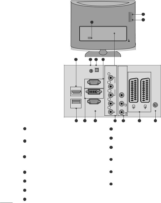
BACK PANEL INFORMATION
■ This is a simplified representation of the back panel. The image shown may be somewhat different from your set.
1
3
2
3 |
4 |
5 |
6 |
|
|
|
COMPONENT AV IN 3 |
|
AUDIO IN |
|
IN |
|
(RGB/DVI) |
|
|
|
|
OPTICAL |
Y |
|
|
AV 1 |
AV 2 |
|
|
DIGITAL |
|
|
|
|
|
|
|
AUDIO OUT |
|
|
|
|
|
|
|
|
PB |
VIDEO |
|
|
|
HDMI IN 1 |
|
RGB IN (PC) |
|
|
|
|
|
|
|
|
|
|
|
|
|
|
|
|
PR |
|
|
VIDEO |
|
|
|
DVI-D IN (PC) |
L |
|
|
ANTENNA/ |
|
|
|
|
|
|
(MONO) |
||
|
|
|
|
|
|
CABLE IN |
|
|
|
|
|
AUDIO |
|
-AUDIO- L |
|
USB IN |
|
RS-232C IN |
R |
|
|
||
|
(CONTROL & SERVICE) |
|
|
|
|
||
|
|
|
|
|
|
R |
|
7 |
8 |
9 |
|
10 |
11 |
12 |
13 |
1 PCMCIA (Personal Computer Memory Card International Association) Card Slot
This feature is not available in all countries.
2Power Cord Socket
This set operates on AC power. The voltage is indicated on the Specifications page. Never attempt to operate the set on DC power.
3HDMI Input (Not Support PC) Connect a HDMI signal to HDMI IN.
Or DVI (VIDEO) signal to HDMI IN with DVI to HDMI cable.
4RGB/DVI Audio Input Connect the audio from a PC.
5Optical Digital Audio Out
Connect digital audio from various types of eguipment
6RGB INPUT (PC)
Connect the output from a PC.
7 USB IN
8DVI-D Input
Connect the output from a PC.
9RS-232C IN (CONTROL & SERVICE) PORT Connect to the RS-232C port on a PC.
10 Component Input
Connect a component video/audio device to these jacks.
11Audio/Video Input
Connect audio/video output from an external device to these jacks.
12Euro Scart Socket (AV1/AV2)
Connect scart socket input or output from an external device to these jacks.
13Antenna Input
Connect over-the-air signals to this jack.
2

PREPARATION |
<M1962D/M2062D/M2262D/M2362D> |
|
STAND INSTALLATION
■ The image shown may be somewhat different from your set.
1 Carefully place the product screen side down on a |
2 Insert the stand base into the product |
cushioned surface that will protect product and |
|
screen from damage. |
|
3Turn the Stand Base Lock through 90° to fix the Stand Base to the Stand Body.
N
E
P O
O
P
E
N
Base Lock
4
N
E
P
O
5
O
P
E
N
<Locked>
3
EXTERNAL EQUIPMENT SETUP
■To prevent the equipment damage, never plug in any power cords until you have finished connecting all equipment.
■The image shown may be somewhat different from your set.
HD RECEIVER SETUP
When connecting with a component cable
1Connect the SET-TOP outputs to the COMPONENT IN VIDEO sockets (Y PB PR) on the set.
2Connect the audio cable from the SET-TOP to COMPONENT IN AUDIO sockets of the set.
3Press the INPUT button to select Component.
Signal |
Component |
HDMI |
||
|
|
|
|
|
|
|
|
|
|
480i/576i |
Yes |
No |
||
480p/576p |
Yes |
Yes |
||
720p/1080i |
Yes |
Yes |
||
1080p |
Yes |
Yes |
||
|
|
|
|
|
|
|
|
|
|
|
|
|
|
|
14
EXTERNAL EQUIPMENT SETUP
When connecting with a HDMI
1 |
Connect the HDMI output of the digital set-top box to the |
HDMI IN jack on the set. |
HDMI IN 1
or
1
HDMI IN 2
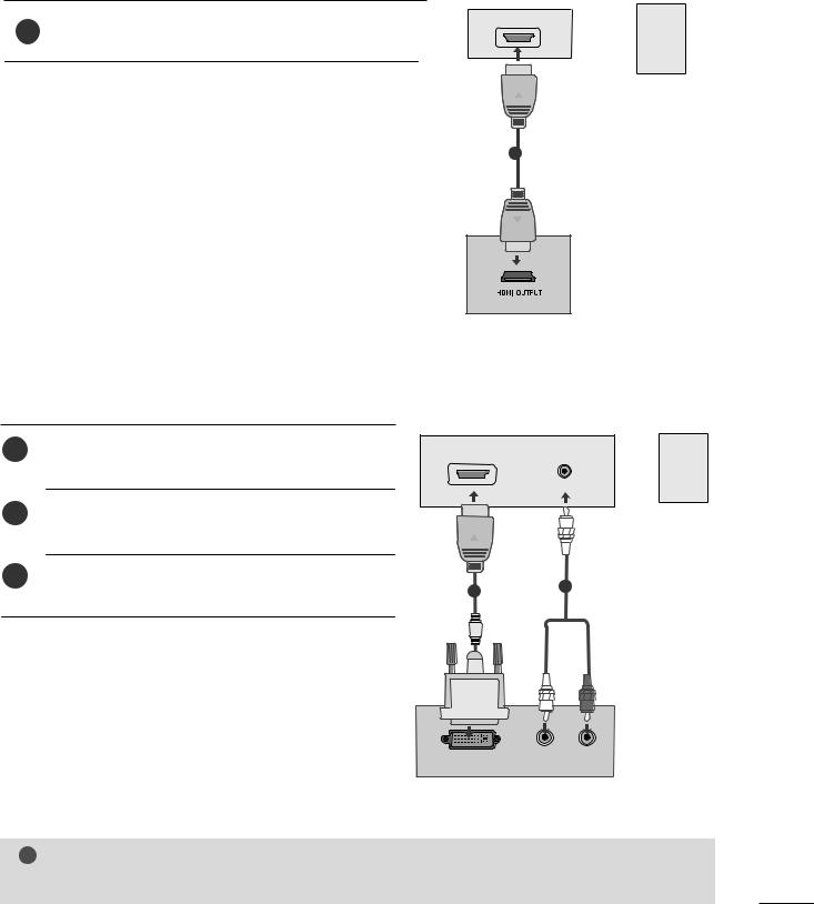
When connecting with a HDMI to DVI cable
1Connect the digital set-top box to HDMI IN jack on the set.
2Connect the audio output of the digital set-top box to the AUDIO IN (RGB/DVI) jack on the set.
3Turn on the digital set-top box. (Refer to the owner’s manual for the digital set-top box.)
HDMI IN 1
AUDIO IN (RGB/DVI)
12
or
HDMI IN 2
L |
AUDIO |
R |
DVI OUTPUT
! NOTE
G HDMI Input does not support PC mode. If it is connected PC, the screen may not be displayed properly.
15
EXTERNAL EQUIPMENT SETUP
DVD SETUP
When connecting with a component cable
1 |
Connect the video output sockets (Y PB PR) of the DVD to |
the COMPONENT IN VIDEO sockets (Y PB PR) of the set. |
2Connect the audio cable from the DVD to COMPONENT IN AUDIO sockets of the set.
3 Press the INPUT button to select Component.
4Press the PLAY button on the DVD.
The DVD playback picture appears on the screen.
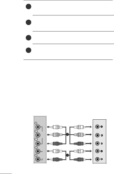
Component Input ports
To get better picture quality, connect a DVD player to the component input ports as shown below.
Component ports on the set |
Y |
PB |
PR |
|
|
|
|
|
|
|
|
|
Y |
PB |
PR |
Video output ports |
Y |
B-Y |
R-Y |
on DVD player |
Y |
Cb |
Cr |
|
Y |
Pb |
Pr |
|
|
|
|
COMPONENT
IN
Y
PB
PR |
VIDEO |
|
|
L |
|
R |
AUDIO |
|
1
2
16
EXTERNAL EQUIPMENT SETUP
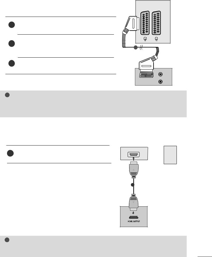
When connecting with a Euro Scart[DVD] |
AV 1 AV 2 |
|
1 |
Connect the Euro scart socket of the DVD to the Euro scart |
|
socket of the set. |
|
|
2 |
Press the INPUT button to select AV1. |
|
|
If connected to AV2 Euro scart socket, select AV2 input |
1 |
|
source. |
|
3 |
Press the PLAY button on the DVD. |
|
|
The DVD playback picture appears on the screen. |
|
(R)
(L) AUDIO
AUDIO/
VIDEO
! NOTE
GSignal type RGB, i.e. the signals red, green and blue can only be selected for the Euro scart and the AV 1 can be received. These signals are transmitted, for example, by a paid TV decoder, game machine or photo CD unit, etc.
GPlease use shielded scart cable.
When connecting HDMI cable
1 |
Connect the HDMI output of the DVD to the |
|
HDMI IN jack on the set. |
||
|
HDMI IN 1
or
HDMI IN 2
1
! NOTE
G Set can receive the video and audio signal simultaneously by using a HDMI cable.
G If the DVD player does not support Auto HDMI, you need to set the DVD output resolution appropriately.
17
EXTERNAL EQUIPMENT SETUP
VCR SETUP
■To avoid picture noise (interference), leave an adequate distance between the VCR and set.
■Typically a still picture is shown on the VCR. If a user uses 4:3 picture format for a long time, an afterimage may remain on the sides of the screen.
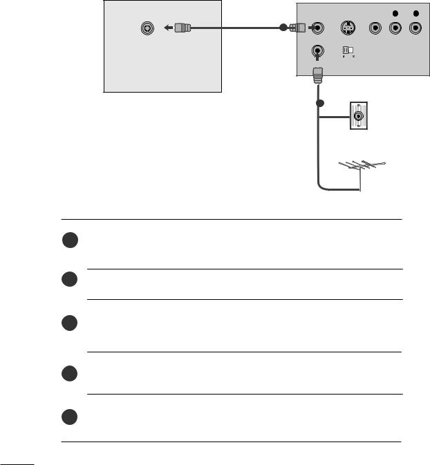
When connecting with an antenna
ANTENNA/ |
ANT OUT |
S-VIDEO VIDEO |
L |
R |
|
CABLE IN |
|||||
|
|
|
|
||
|
1 |
|
|
|
|
|
ANT IN |
OUTPUT |
|
|
|
|
SWITCH |
|
|
||
|
|
|
|
Wall Jack
2
Antenna
1Connect the RF out socket of the VCR to the aerial socket of the set.
2Connect the aerial cable to the RF aerial in socket of the VCR.
3Store the VCR channel on a desired programme number using the ‘Manual programme tuning’ section.
4Select the programme number where the VCR channel is stored.
5 Press the PLAY button on the VCR.
18
EXTERNAL EQUIPMENT SETUP
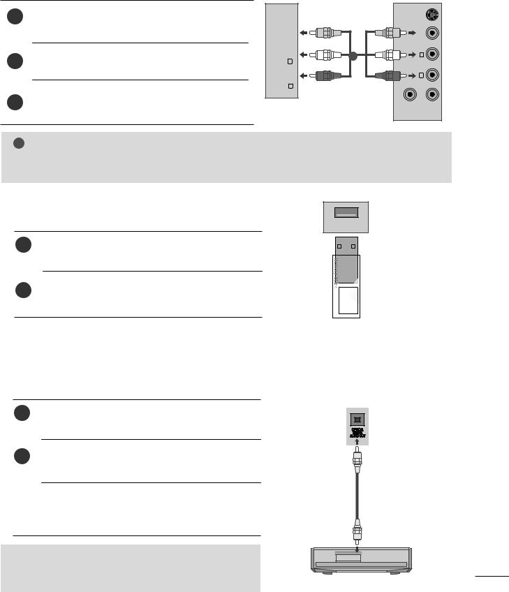
When connecting with a RCA cable
1Connect the audio/video out sockets of the VCR to AUDIO/VIDEO in sockets of the set.
2Press the INPUT button to select AV3.
3Press the PLAY button on the VCR.
The VCR playback picture appears on the screen.
AV-IN 3
R AUDIO L (MONO) VIDEO
1
|
VIDEO VIDEO-S |
|
L |
|
R |
OUT ANT |
IN ANT |
! NOTE
G If you have a mono VCR, connect the audio cable from the VCR to the AUDIO L/MONO jack of the set.
USB SETUP
USB IN
1Connect the USB device to the USB IN jacks on the side of set.
2 |
After connecting the USB IN jacks, you use the USB |
|
function. (G p.92) |
||
|
DIGITAL AUDIO OUT SETUP
Sending the TV’s audio signal to external audio equipment via the Digital Audio Output (Optical) port.
If you want to enjoy digital broadcasting through 5.1-channel speakers, connect the OPTICAL DIGITAL AUDIO OUT terminal on the back of TV to a DVD Home Theater (or amp).
1Connect one end of an optical cable to the TV Digital
Audio (Optical) Output port.
2 |
Connect the other end of the optical cable to the digi- |
|
tal audio (Optical) input on the audio equipment. |
Set the “TV Speaker option - Off ” in the AUDIO menu.(G p.71). Refer to the external audio equipment instruction manual for operation.
 CAUTION
G Do not look into the optical output port. Looking at the laser beam may damage your vision.
19
EXTERNAL EQUIPMENT SETUP
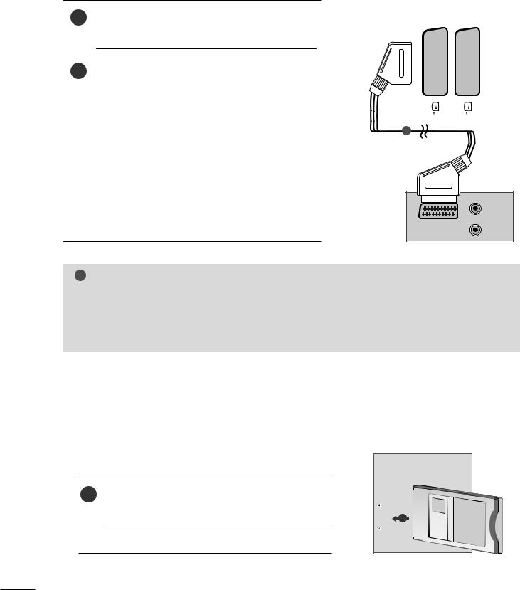
When connecting with a Euro Scart[VCR]
1Connect the Euro scart socket of the VCR to the Euro scart socket of the set.
Press the PLAY button on the VCR.
2If your VCR outputs an AV switching signal via the Scart lead, the set will auto switch to AV 1 mode on start of playback, but if you want to keep on watching in TV mode, press the D / E or NUMBER buttons.
If connected to AV2 Euro scart socket, select AV2 input source.
Otherwise press the INPUT button on the remote control handset to select AV 1. The VCR playback picture appears on the screen.
You can also record programmes received by the set on video tape.
|
|
AV 1 |
AV 2 |
||
|
|
|
|
|
|
|
|
|
|
|
|
|
|
|
|
|
|
|
|
|
|
|
|
|
|
|
|
|
|
|
|
|
|
|
|
|
|
|
|
|
|
|
|
|
|
|
|
|
|
|
|
|
|
|
|
|
|
|
|
|
|
|
|
|
|
|
|
|
|
|
|
|
|
|
|
|
|
|
|
|
|
|
|
1
(R)
(L) AUDIO
AUDIO/
VIDEO
! NOTE
GSignal type RGB, i.e. the signals red, green and blue can only be selected for the Euro scart and the AV 1 can be received. These signals are transmitted, for example, by a paid TV decoder, game machine or photo CD unit, etc.
GPlease use shielded scart cable.
INSERTION OF CI MODULE
-To view the scrambled (paid) services in digital TV mode.
-This feature is not available in all countries.
Insert the CI Module to PCMCIA (Personal Computer
1Memory Card International Association) CARD SLOT of set as shown.
For further information, see p. 40.
PCMCIA CARD SLOT
1
TV
20

EXTERNAL EQUIPMENT SETUP
PC SETUP
This product provides Plug and Play capability, meaning that the PC adjusts automatically to the set's settings.
When connecting with a D-sub 15 pin cable
1Connect the signal cable from the monitor output socket of the PERSONAL COMPUTER to the PC input socket of the set.
RGB IN (PC)
2 Connect the audio cable from the PC to the AUDIO IN (RGB/DVI) sockets of the set.
AUDIO IN (RGB/DVI)
3
4
Press the INPUT button to select RGB.
Switch on the PC, and the PC screen appears on the set.
The set can be operated as a PC monitor.
1 |
2 |
|
|
|
|
|
|
|
|
|
|
|
|
|
|
|
|
|
|
|
|
|
|
|
|
|
|
|
|
|
|
|
|
|
|
|
|
|
|
|
|
|
|
|
|
|
RGB OUTPUT |
AUDIO |
|||||||
|
|
|
||||||
|
|
|
|
|
|
|
|
|
! NOTE
G You must use shielded signal interface cables (D sub 15 pin cable, DVI cable) with ferrite cores to maintain standard compliance for the product.
21
EXTERNAL EQUIPMENT SETUP
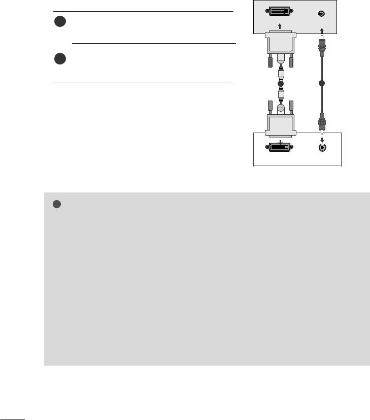
When connecting with a DVI cable
1Connect the DVI output of the PC to the DVI-D IN jack on the set.
2Connect the audio cable from the PC to the AUDIO IN (RGB/DVI) sockets of the set.
AUDIO IN (RGB/DVI)
DVI-D IN (PC)
1 |
2 |
|
|
|
|
|
|
|
|
|
|
|
|
|
|
|
|
|
|
|
|
|
|
|
|
|
|
|
|
|
|
|
|
|
|
|
|
|
|
|
|
|
|
|
|
|
|
|
|
|
|
|
|
AUDIO |
||
|
DVI OUTPUT |
|
||||||||
|
|
|
|
|
||||||
|
|
|
|
|
|
|
|
|
|
|
! NOTE
G If the set is cold, there may be a small “flicker” when the set is switched on. This is normal, there is nothing wrong with the set.
G If possible, use the 1360x768 @ 60 Hz video mode to obtain the best image quality for your LCD monitor. If used with other resolutions, some scaled or processed pictures may appear on the screen. The set has been preadjusted to the mode 1360 x 768 @ 60 Hz.(M1962D)
G If possible, use the 1600 x 900 @ 60 Hz video mode to obtain the best image quality for your LCD monitor. If used with other resolutions, some scaled or processed pictures may appear on the screen. The set has been preadjusted to the mode 1600 x 900 @ 60 Hz.(M2062D)
G If possible, use the 1920 x 1080 @ 60 Hz video mode to obtain the best image quality for your LCD monitor. If used with other resolutions, some scaled or processed pictures may appear on the screen. The set has been preadjusted to the mode 1920 x 1080 @ 60 Hz. (M2262D/M2362D/M2762D)
G Some dot defects may appear on the screen, like Red, Green or Blue spots. However, this will have no impact or effect on the monitor performance.
G Do not press the LCD screen with your finger for a long time as this may produce some temporary distortion effects on the screen.
GAvoid keeping a fixed image on the set’s screen for prolonged periods of time. The fixed image may become permanently imprinted on the screen; use a screen saver when possible.
22
EXTERNAL EQUIPMENT SETUP
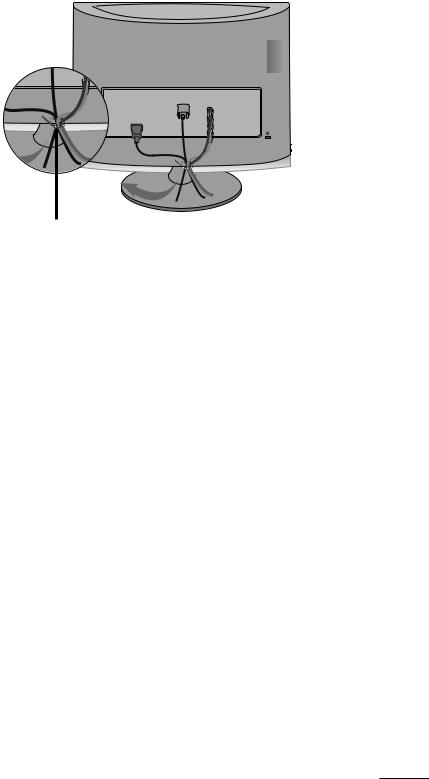
BACK COVER FOR WIRE ARRANGEMENT
Tie cables together with a cable tie as shown in the illustration.
R
R
Cable tie
23
EXTERNAL EQUIPMENT SETUP
RGB/DVI[PC]
<M1962D>
Resolution |
Horizontal |
Vertical |
|
Frequency(kHz) |
Frequency(Hz) |
||
|
|||
|
31.469 |
60 |
|
640x480 |
|||
37.5 |
75 |
||
|
|||
800x600 |
37.879 |
60 |
|
46.875 |
75 |
||
|
|||
1024x768 |
48.363 |
60 |
|
60.123 |
75 |
||
|
|||
1280x768 |
47.776 |
60 |
|
1280x800 |
49.306 |
60 |
|
1360x768 |
47.712 |
60 |
|
47.7 |
60 |
||
|
|||
|
|
|
<M2062D>
Resolution |
Horizontal |
Vertical |
|
Frequency(kHz) |
Frequency(Hz) |
||
|
|||
|
|
|
|
720x350 |
25.175 |
70 |
|
720x400 |
31.468 |
70 |
|
640x480 |
31.469 |
60 |
|
37.5 |
75 |
||
|
|||
800x600 |
37.879 |
60 |
|
46.875 |
75 |
||
|
|||
832x624 |
49.725 |
65 |
|
1024x768 |
48.363 |
60 |
|
60.123 |
75 |
||
|
|||
1152x870 |
68.681 |
75 |
|
1280x1024 |
63.981 |
60 |
|
1280x1024 |
79.976 |
75 |
|
1600x900 |
60 |
60 |
|
|
|
|
HDMI[DTV] (Not Support PC)
Resolution |
Horizontal |
Vertical |
|
Frequency(kHz) |
Frequency(Hz) |
||
|
|||
|
31.469 |
60 |
|
720x480/60p |
|||
31.5 |
60 |
||
|
|||
720x576/50p |
31.25 |
50 |
|
1280x720/50p |
37.5 |
50 |
|
1280x720/60p |
44.96 |
60 |
|
45 |
60 |
||
|
|||
1920x1080/60i |
33.72 |
60 |
|
33.75 |
60 |
||
|
|||
1920x1080/50i |
28.125 |
50 |
|
1920x1080/24p |
27 |
24 |
|
1920x1080/30p |
33.75 |
30 |
|
1920x1080/50p |
56.25 |
50 |
|
1920x1080/60p |
67.43 |
60 |
|
67.5 |
60 |
||
|
|||
|
|
|
<M2262D/M2362D/M2762D>
Resolution |
Horizontal |
Vertical |
|
Frequency(kHz) |
Frequency(Hz) |
||
|
|||
|
|
|
|
720x400 |
31.468 |
70 |
|
640x480 |
31.469 |
60 |
|
37.500 |
75 |
||
|
|||
800x600 |
37.879 |
60 |
|
46.875 |
75 |
||
|
|||
1024x768 |
48.363 |
60 |
|
60.123 |
75 |
||
|
|||
1152x864 |
67.500 |
75 |
|
1280x1024 |
63.981 |
60 |
|
79.976 |
75 |
||
|
|||
1680x1050 |
64.674 |
60 |
|
65.290 |
60 |
||
|
|||
1600x1200 |
75.000 |
60 |
|
1920x1080 |
66.587 |
60 |
|
|
|
|
24
WATCHING TV /PROGRAMME CONTROL
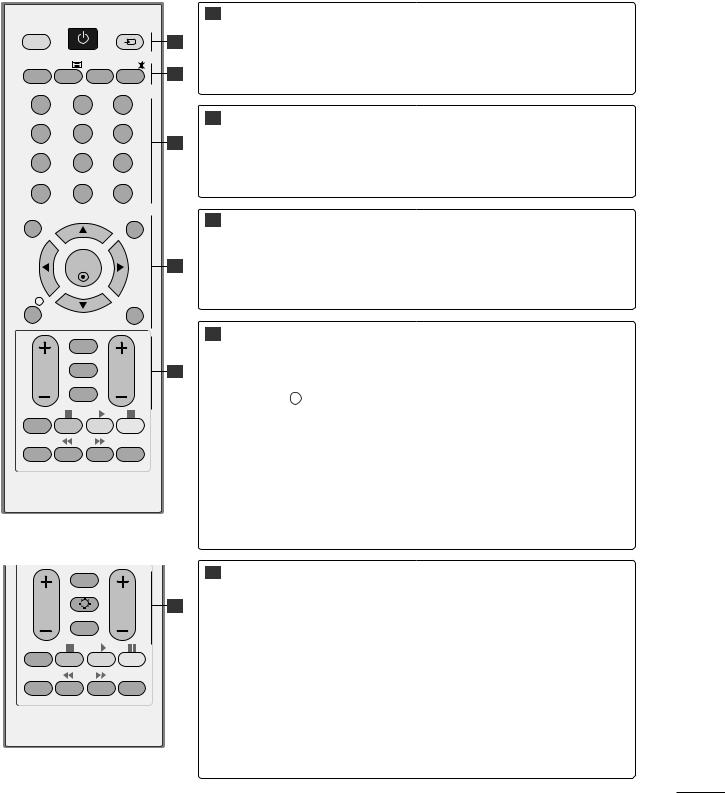
REMOTE CONTROL KEY FUNCTIONS
When using the remote control, aim it at the remote control sensor on the set.
A TYPE
|
|
POWER |
|
1 |
POWER |
Switches the set on or off. |
|
|
|
|
|
||||
TV/PC |
|
INPUT |
|
|
|
||
|
|
|
|
|
|
||
|
|
|
|
|
1 |
TV/PC |
Selects TV or PC mode. |
|
|
|
|
|
|
||
TV/RADIO |
TEXT |
I/II |
MUTE |
2 |
INPUT |
External input mode rotates in regular sequence. |
|
|
|
|
|
|
|||
1 |
|
2 |
|
3 |
|
|
|
4 |
|
5 |
|
6 |
2 |
TV/RADIO |
Selects Radio or TV channel. |
|
|
3 |
|
|
|||
|
|
|
|
|
I/II |
Selects the sound output.(Refer to the p.73~74) |
|
7 |
|
8 |
|
9 |
|
||
|
|
|
|
|
|||
LIST |
|
0 |
|
Q.VIEW |
|
MUTE |
Switches the sound on or off. |
|
|
|
|
|
|||
MENU |
|
|
|
EXIT |
3 |
0~9 number |
Selects a programme. |
|
|
|
|
|
|||
|
|
|
|
|
|
button |
Selects numbered items in a menu. |
|
|
OK |
|
4 |
LIST |
Displays the programme table.(Refer to the p.41) |
|
|
|
|
|
|
|||
INFO i |
|
|
|
GUIDE |
|
Q.VIEW |
Returns to the previously viewed programme. |
|
|
RETURN |
|
4 |
MENU |
Selects a menu. (Refer to the p.30) |
|
|
|
|
|
|
|
||
VOL |
* |
|
PR |
5 |
EXIT |
Clears all on-screen displays. |
|
|
|
|
|
|
|
|
|
|
|
FAV |
|
|
INFO i |
Shows the present screen information. |
|
|
|
|
|
|
|
||
Q.MENU |
|
T.OPT |
SUBTITLE |
MARK |
|
GUIDE |
Shows programme schedule.(Refer to the p.42~45) |
|
|
|
|
||||
|
|
|
|
|
|
THUMBSTICK |
Allows you to navigate the on-screen menus and adjust the |
|
|
|
|
|
(Up/Down/Left/Right) |
system settings to your preference. |
|
|
|
|
|
|
|
OK Accepts your selection or displays the current mode. |
|
B TYPE |
|
|
|
|
|
|
|
|
|
RETURN |
|
5 |
VOLUME UP |
Adjusts the volume. |
|
|
|
|
|
/DOWN |
|
||
|
|
LIGHTING |
|
|
|
||
VOL |
|
|
PR |
5 |
|
|
|
|
|
FAV |
|
|
RETURN |
Allows the user to move back one step in an interactive applica- |
|
|
|
|
|
|
tion, EPG or other user interaction function. |
||
|
|
|
|
|
|
|
|
|
|
|
|
|
|
* |
A TYPE : No function |
Q.MENU |
|
T.OPT |
SUBTITLE |
MARK |
|
LIGHTING |
B TYPE : Press the Lighting button to turn the decoration light- |
|
|
|
ing on/off. |
||||
|
|
|
|
|
|
|
|
|
|
|
|
|
|
FAV |
Displays the selected favourite programme.(Refer to the p.41) |
|
|
|
|
|
|
Programme |
Selects a programme. |
|
|
|
|
|
|
UP/DOWN |
|
25
 Loading...