


 Loading...
ENGLISH
OWNER’S MANUAL
MONITOR SIGNAGE
Please read this manual carefully before operating your set and retain it for future reference.
MONITOR SIGNAGE MODELS
M2901S
M3801S
www.lg.com
Note • Image sticking is a phenomenon that exhibits temporary retained image or permanent "ghost" image, due to the prolonged display of static images, which causes chemical or electrical damage on the display components.
•It is recommended to avoid displaying a fixed static image which is the most common cause of image sticking.
•When a displayed image is not required, it is recommended to display a Dynamic Image, or an Active moving Screen Saver.
•Typical Example of Image Sticking
1)For general usage, such as television broadcasting, image sticking can occur on channel numbers or logos displayed in a fixed position for long periods of time.
2)The displays used at airports and other public transportation stations for displaying customer information, tend to have the same image or similar contents. Image Sticking occurs when this type of format or content is used for a long period of time.
3)Letter box format is consistently used with DVD or VCR.
4)When OSD (On Screen Display) such as "Menu" is consistently present on the screen.
•Power down the product for a period of time that matches that which caused the issue.
For example, if image sticking occurred after one hour with certain static image, it will take one hour to eliminate.
•This phenomenon is common to all manufactures and in consequence the manufactures warranty does not cover the product bearing this phenomenon.
2

Using the Remote Control.......................................................... |
4 |
Name of the Remote Control Buttons.............................................................................. |
4 |
Inserting batteries into remote control............................................................................. |
4 |
Name and Function of the Parts................................................ |
5 |
Rear View.............................................................................................................................. |
5 |
Connecting to External Devices................................................ |
6 |
When Connecting to your PC............................................................................................ |
6 |
When using the LAN........................................................................................................... |
7 |
Daisy Chain Monitors.......................................................................................................... |
8 |
VESAFDMI wall Mounting.................................................................................................. |
9 |
User Menus.................................................................................. |
10 |
ScreenAdjustment options............................................................................................... |
10 |
OSD Menu............................................................................................................................ |
12 |
How to adjust the OSD (On Screen Display) screen...................................................... |
12 |
How to adjust the screen automatically........................................................................... |
12 |
Adjusting Screen Color....................................................................................................... |
13 |
Adjusting the Time function............................................................................................... |
15 |
Adjusting OSD image.......................................................................................................... |
17 |
Selecting the UTILITY.......................................................................................................... |
18 |
Adjusting UTILITY................................................................................................................ |
19 |
Troubleshooting.......................................................................... |
20 |
Specifications ............................................................................ |
23 |
Controlling the Multiple Product............................................... |
A1 |
3

Using the Remote Control
 Name of the Remote Control Buttons
• Power Button |
|
|
|
|
|
|
• Input Button |
|
|
|
|
|
|
||||
Power On/Off |
|
|
|
|
|
|||
|
|
|
|
|
Select Input Source |
|||
|
|
|
|
|
|
|
|
|
There is not a function |
|
|
|
|
|
|
|
(RGB, HDMI) |
|
|
|
|
|
|
|||
which is supported |
|
|
|
|
|
|
||
|
|
|
|
|
|
|||
• Sleep Button
Select Sleep Time
• ARC button
Aspect Ratio Correction. Toggles through aspect ratio options.
• AUTO button
Automatic adjustment function (Operational for the analog signal only).
• PSM
There is not a function which is supported.
|
• Key Button |
There is not a function |
There is not a function |
which is supported |
which is supported |
• Menu Button |
• Exit Button |
OSD On/Off |
Menu Exit |
Sub OSD Menu out |
• ▲ ▼ Buttons |
|
|
|
OSD Menu Navigation |
|
• ◄ ► Buttons |
|
Select/ Adjust OSD Menu Item |
|
• SET |
|
Select OSD Menu Item |
There is not a function |
Show input resolution information |
|
|
which is supported |
There is not a function |
|
which is supported |
 Inserting batteries into remote control.
|
1. |
Open the battery compartment cover on the back side and |
|
|
|
install the batteries matching correct polarity (+ with +,- with -) |
|
|
2. |
Install two 1.5 V AAA batteries. Don’t mix old or used batteries |
|
|
|
with new ones. |
|
AAAType |
3. |
Close cover. |
|
4. To remove the batteries, perform the installation actions in |
|||
|
|||
reverse.
4
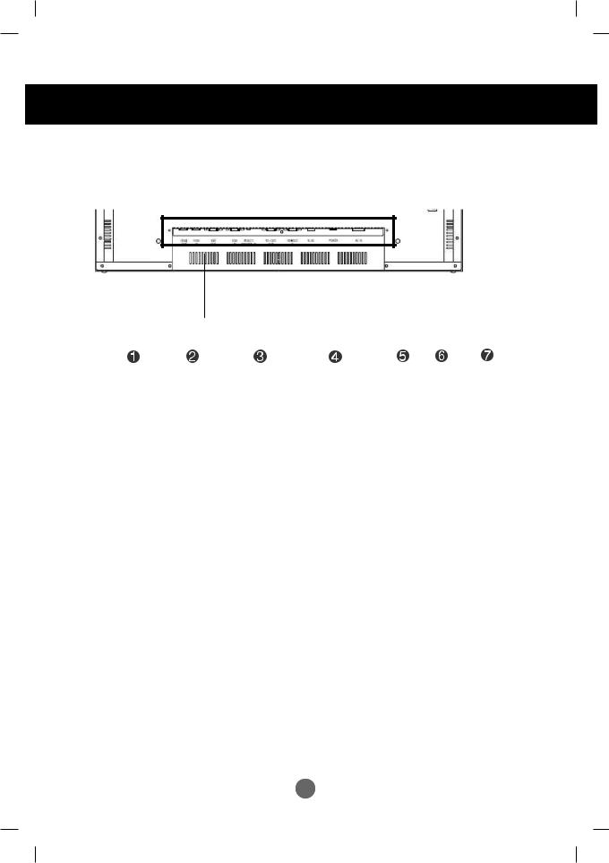
Name and Function of the Parts
* The product image in the user's guide could be different from the actual image.
 Rear View
HDMI |
RGB |
RGB |
EXT. IR |
RS-232C |
RS-232C RJ45 POWER |
AC IN |
IN |
OUT |
IN |
|
OUT |
IN |
|
|
|
|
|
|
|
|
 HDMI IN Ports : HDMI signal to HDMI port with HDMI cable.
 RGB IN/OUT : RGB signal to RGB port with RGB cable.
 EXT. IR : External IR
 RS-232C Serial IN/OUT Port : Connect to the RS-232C port on a PC. For control the another set, connect a RS-232C Cable from RS-232C out port to another set's RS-232C input port.
 RJ45(eZNET) Port : Connect the LAN cable for eZNET Manager control.
 Power Switch : AC Power On/Off Switch
 AC Power Connector : Connect the power cord
5
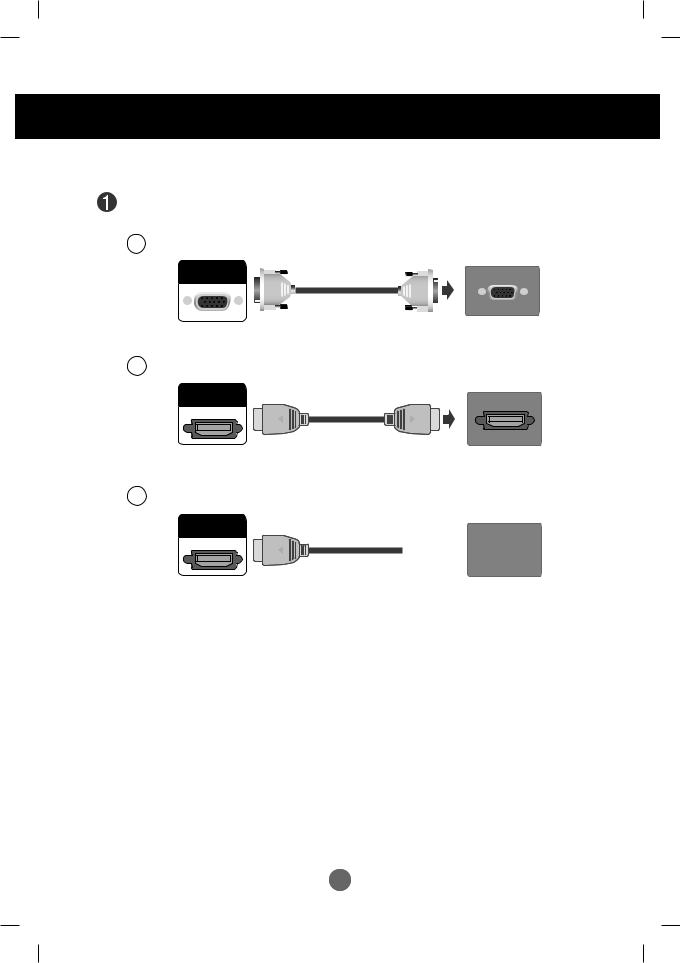
Connecting to External Devices
 When Connecting to your PC
First of all, see if the computer, product and the peripherals are turned off. Then, connect the signal input cable.
A When connecting with the D-Sub signal input cable.
RGB
IN
Rear side of the product.
B When connecting with the HDMI signal input cable (not included).
HDMI
IN
(not included)
Rear side of the product.
PC
PC
C When connecting with the HDMI to DVI signal input cable (not included).
HDMI
IN
|
(not included) |
Rear side of the product. |
PC |
|
 Connect the power cord.
Rear side of the product.
Note |
• If HDMI signal of input device is abnormal, Something wrong phenomenon or no signal can |
|
|
|
happen on screen. |
|
|
|
|
6
Connecting to External Devices
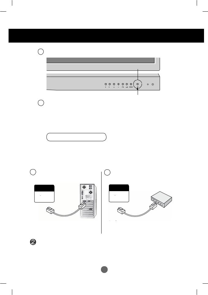
 1 Turn on power by pressing the power button on the product.
Power button
2 Turn on the PC.
To change input source
Press the SOURCE button on the remote control to select the input signal. Or, press the SOURCE button on the bottom of the product.
HDMI signal 
 D-sub signal
 When using the LAN
 Connect the LAN cable as shown in the below figure .
A When connecting with a PC.
B When connecting with a Network.
RJ45 |
RJ45 |
|
|
|
|
|
Product |
PC |
|
Product |
Network |
Connect the LAN cable and install the eZ-Net Manager program on the CD-ROM. For more information about the program, please refer to eZ-Net Guide in the enclosed CD-ROM.
7
Connecting to External Devices
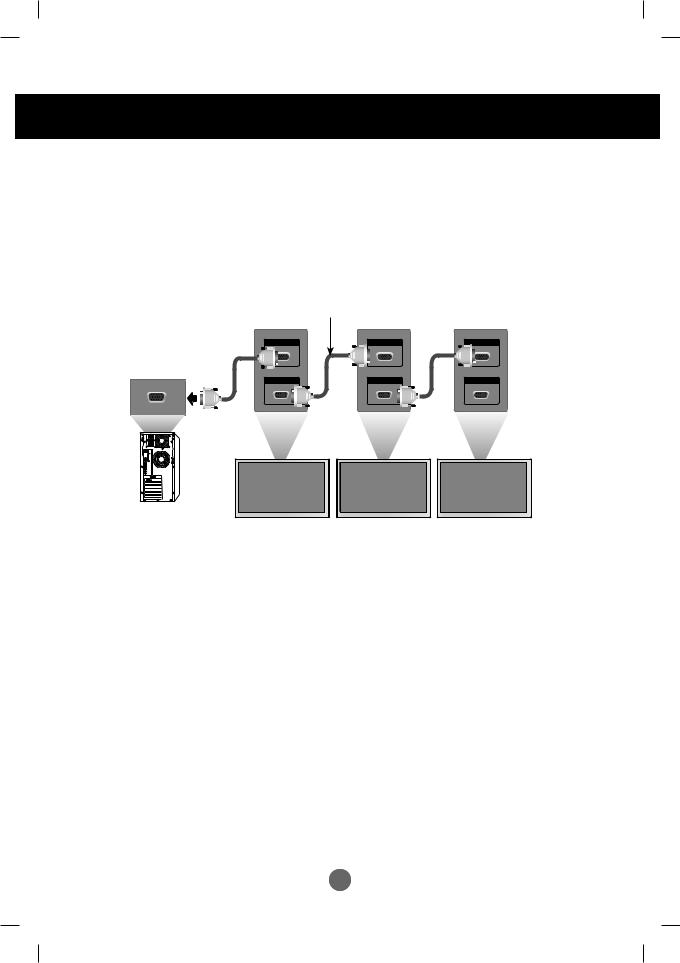
 Daisy Chain Monitors
Use this function when displaying ANALOG RGB inputs of a PC to the other product.
• To use different products connected to each other
Connect one end of the signal input cable(15-pin D-Sub Signal Cable) to the RGB OUT connector of product 1 and connect the other RGB IN connector of other products.
Case Analog RGB Connect (Maximum 1.8 m)
RGB IN |
RGB IN |
RGB IN |
RGB OUT |
RGB OUT |
RGB OUT |
PC
Product 1 |
Product 2 |
Product 3 |
8
Connecting to External Devices
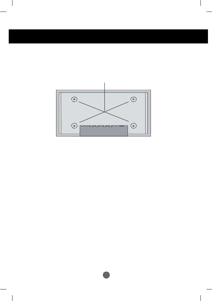
 VESA FDMI wall Mounting
This product supports a VESA FDMI compliant mounting interface. These mounts are Purchased separately and not available. Refer to the instructions included with the mount for more info
9
User Menus
 Screen Adjustment options
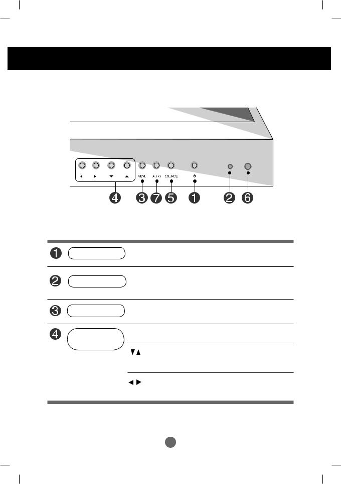
Power Button
•Press this button to turn on the power. Press this button again to turn it off.
•This Indicator lights up green when the display operates normally (on Power Indicator mode). If the display is in sleep (Energy Saving) mode, this indicator color
changes to red.
MENU Button
•Use this button to show/hide the OSD (On Screen Display) menu screen.
OSD Select /
Adjust Button
• Use this button to select an icon or adjust the setting in the OSD screen.
OSD Menu Navigation up and down
▼ : Aspect Ratio Hot key (TOP → Bottom → Stretch)
◄ : Select Menu Item, Decrement Value
► : Select Menu Item, Increment Value
10
User Menus
 Screen Adjustment options
SOURCE Button |
• To change input source depending on connected signal. |
||
Press the SOURCE button on the remote control to select the input |
|||
|
signal. Or, press the SOURCE button on the bottom of the product. |
||
IR Receiver |
HDMI signal |
|
D-Sub Signal |
|
|||
• This is where the unit receives signals from the remote control. |
|||
|
|
|
|
Auto Config |
• Automatic adjustment function.(Operational for the analog signal only) |
||
|
|
|
|
|
|
|
|
11
User Menus
 OSD Menu
 Adjusts screen brightness, contrast and color that you prefer.
PICTURE
 Adjusts the timer options
TIME
 Adjusts the OSD menu position.
OSD
 Adjusts Set ID and Set Network.
UTILITY
Note OSD(On Screen Display)
The OSD function enables you to adjust the screen status conveniently since it provides graphical presentation.
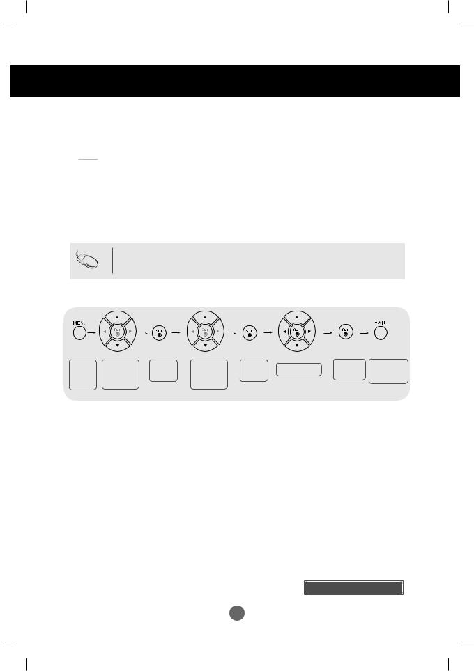
 How to adjust the OSD (On Screen Display) screen
Pops up |
Move where |
Select a |
Move where |
Select a |
Adjust the status |
Save |
Exit from the |
the menu |
you want to |
menu icon |
you want to |
menu icon |
adjustment |
menu screen. |
|
screen |
adjust |
|
adjust |
|
|
|
|
• Use the remote control to adjust the OSD screen.
 Press the MENU Button, then the main menu of the OSD appears.
 To access a control, use the Buttons.
 When the icon you want becomes highlighted, press the Button.
 Use the Buttons to adjust the item to the desired level.
 Accept the changes by pressing the SET Button.
 Exit the OSD by pressing the EXIT Button.
 How to adjust the screen automatically
Press the AUTO button on a remote Control in the PC analog signal. Then optimal screen settings will be selected that fit into the current mode. If adjustment is not satisfactory, you can adjust the screen manually.
Auto Config
12
Loading...