


LM-2164H2L

Multi Type Room
Air Conditioner
SERVICE MANUAL
MODEL: LM-2164H2L/M
LM-3064H3L/M

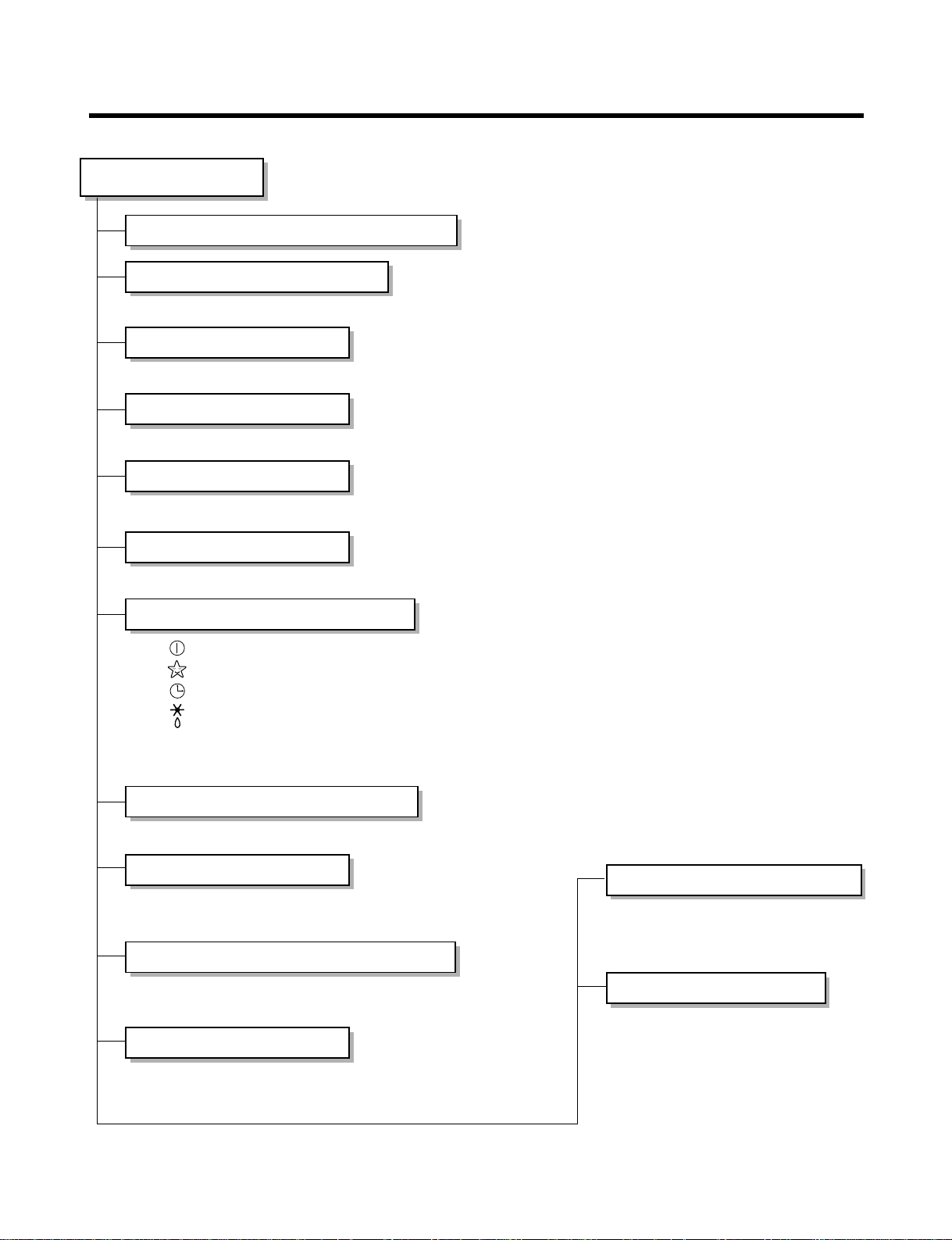
Functions...................................................................................................................................... 3
Product Specifications................................................................................................................ 5
Dimensions................................................................................................................................... 7
Refrigeration Cycle Diagram..................................................................................................... 10
Wiring Diagram .......................................................................................................................... 11
Operation Details ....................................................................................................................... 12
Display Function........................................................................................................................ 19
Self-Diagnosis Function............................................................................................................ 19
Installation.................................................................................................................................. 20
Operation.................................................................................................................................... 34
Disassembly of the parts (Indoor Unit).................................................................................... 36
2-way, 3-way Valve..................................................................................................................... 38
Cycle Troubleshooting Guide ....................................................................................................42
Electronic Parts Troubleshooting Guide.................................................................................. 43
Electronic Control Device ......................................................................................................... 50
Schematic Diagram.................................................................................................................... 53
Exploded View and Replacement Parts List............................................................................ 55
- 2 -
Contents
- 3 -
Functions
• Room temperature sensor. (THERMISTOR)
• Maintains the room temperature in accordance with the Setting Temp.
• Indoor fan is delayed for 5 seconds at the starting.
• Restarting is inhibited for approx. 3 minutes.
• High, Med, Low, Chaos
--- Lights up in operation
--- Lights up in Sleep Mode
--- Lights up in Timer Mode
--- Lights up in Deice Mode(for Heat pump model)
--- Lights up in Compressor operation(for Cooling model)
• Intermittent operation of fan at low speed.
• The fan is switched to low(Cooling), med(Heating) speed.
• The unit will be stopped after 1, 2, 3, 4, 5, 6, 7 hours.
• The fan is switched to intermittent or irregular operation
•
The fan speed is automatically switched from high to low speed.
• The louver can be set at the desired position or swing
up and down automatically.
Indoor Unit
Operation ON/OFF by Remote controller
Sensing the Room Temperature
Room temperature control
Starting Current Control
Time Delay Safety Control
Indoor Fan Speed Control
Operation indication Lamps (LED)
OUT
DOOR
Health Dehumidification Operation
• Both the indoor and outdoor fan
stops during deicing.
• Hot start after deice ends.
• The indoor fan stops until the
evaporator piping temperature will be
reached at 28°C.
Sleep Mode Auto Control
Natural Air Control by CHAOS Logic
Airflow Direction Control
Deice (defrost) control (Heating)
Hot-start Control (Heating)
- 4 -
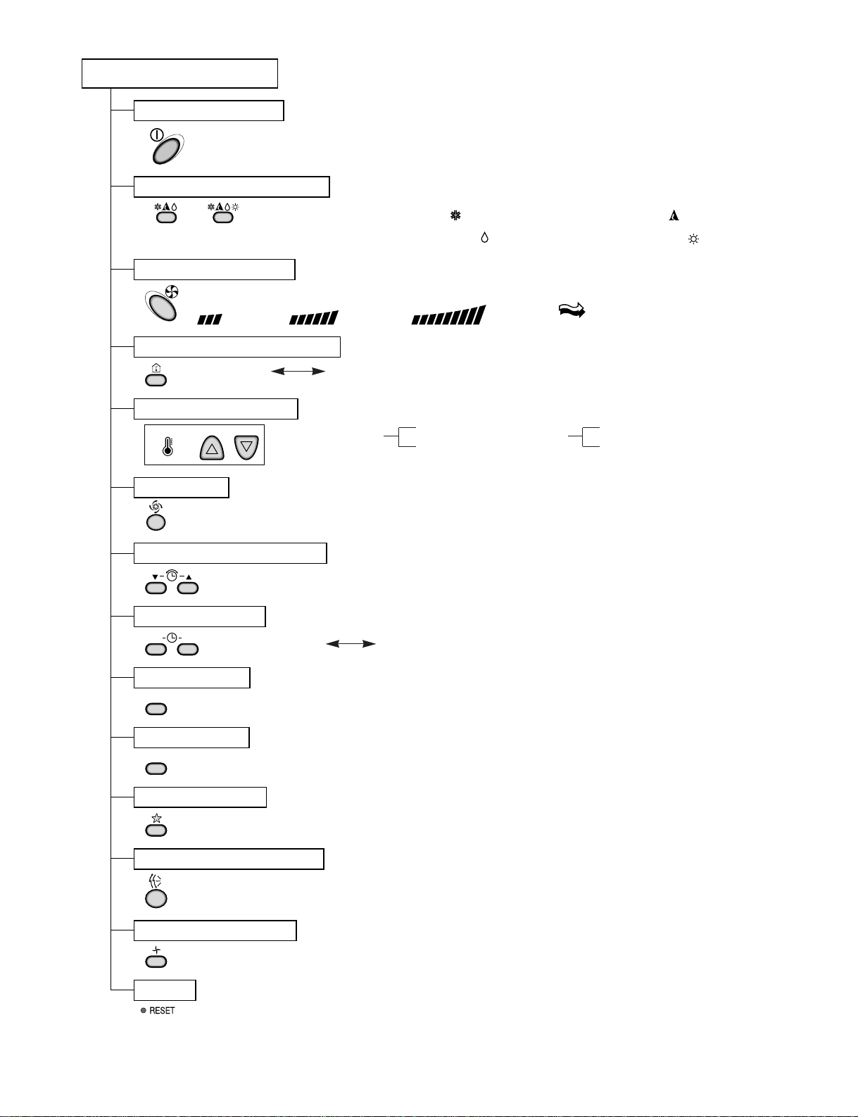
Remote Controller
JET COOL
Healthy Dehumidification Operation Mode.
( )
Operation Mode Selection
(Cooling
model only)
(Heating
model only)
Cooling Operation Mode.( )
Heating Operation Mode.( )
Auto Operation Mode.( )
Sleep Operation
Fan Operation Mode
Room, Temperature Display
Setting the Time or Timer
Airflow Direction Control
Operation ON/OFF
Temperature Setting
TEMPERATURE
LOWHIGH
Timer Selection
ON OFF
Timer Setting
SET
Timer Cancel
CANCEL
Reset
Fan Speed Selection
(Low) (Med) (High) (CHAOS)
: (High: 39°C LOW : 11°C)
Down to 18°C
Up to 30°C
Cooling
: OFF, ON, OFF ON
: Cancel Sleep Mode, Timer ON or Timer OFF
: 1, 2, 3, 4, 5, 6, 7, Off Timer
: Fan Operates without cooling or heating.
Down to 16°C
Up to 30°C
Heating
- 5 -
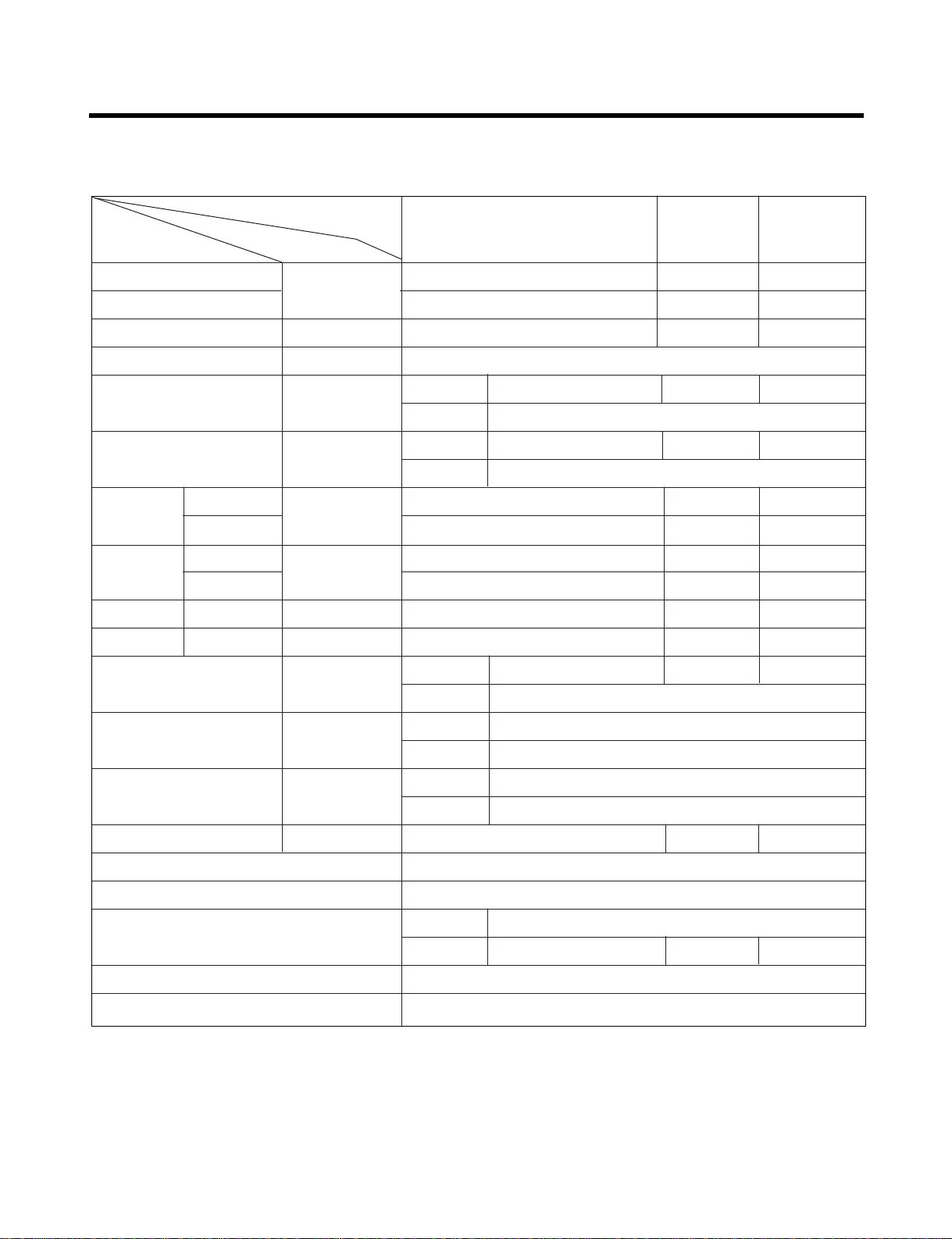
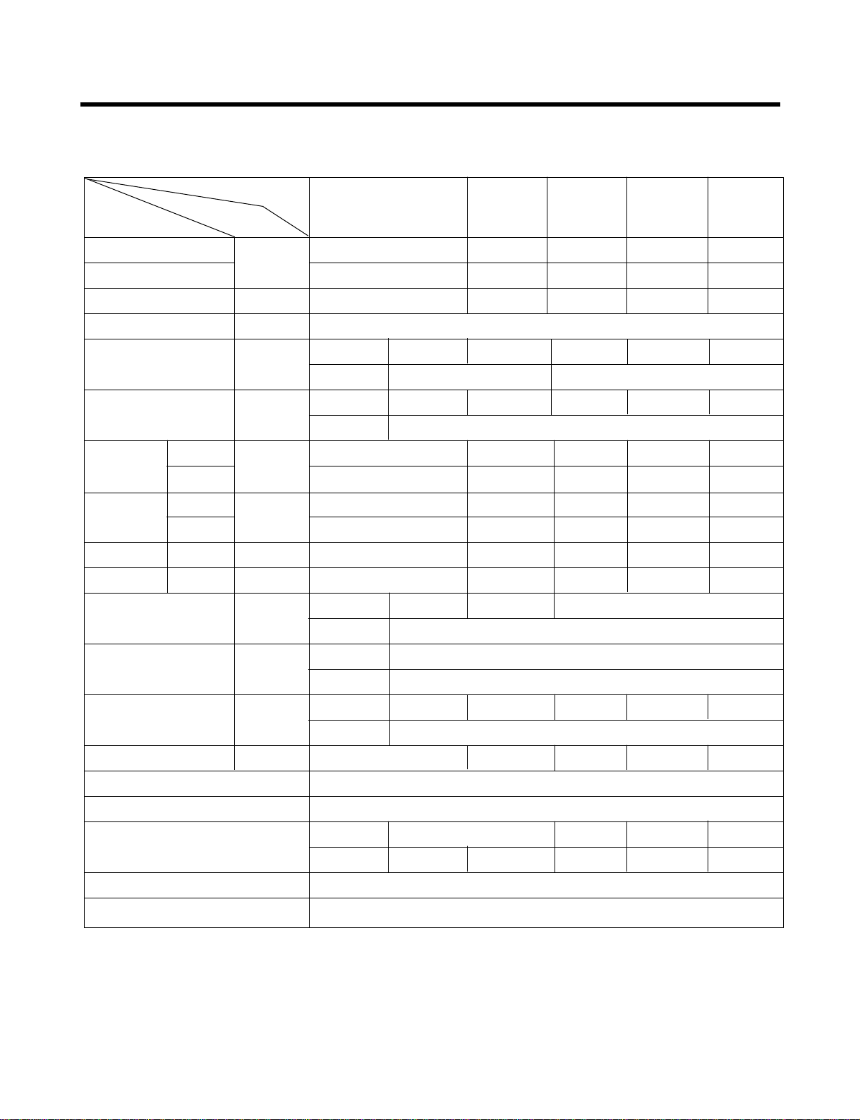
Product Specifications
21,000(5,292) 14,000(3,528) 7,000(1,764)
21,000(5,292) 14,000(3,528) 7,000(1,764)
3.0 2.0 1.0
1Ø, 220-240V, 50Hz
Indoor 10.5 6.5
Outdoor 53
Indoor 41 38
Outdoor 55
2,200 1,420 900
2,200 1,420 830
9.7 6.2 4.0
9.7 6.2 3.8
9.5 9.9 7.8
9.5 9.9 8.4
Indoor 13 7.5
Outdoor 61
Indoor 888 x 287 x 170 / 802 x 262 x 165
Outdoor 870 x 655 x 320
Indoor 10 / 7
Outdoor 62
1,500 990
O
L.C.D Wireless
Liquid 1/4"(6.35)
Gas 1/2"(12.7) 3/8"(9.52)
O
O
Operation
A-Unit OnlyA-Unit + B-Unit B-Unit Only
Unit
Item
Cooling Capacity
Heating Capacity
Moisture Removal §⁄/h
Power Source ø, V, Hz
Air Circulation m
3
/min
Noise Level dB(A)
Input W
A
E.E.R. Btu/h
.
w
C.O.P. -
Motor Output W
Dimensions(W x H x D)
mm
Net. Weight kg
Refrigerant(R-22)(at 7.5m)
g
Airflow Direction Control(Up & Down)
Remocon Type
Service Valve
Sleeping Operation
Drain Hose
Cooling
Heating
Cooling
Heating
Cooling
Heating
Runnig
Current
Btu/h(kcal/h)
1. LM-2164H2L/M
- 6 -
14,000(3,528)
10,000(2,520) 24,000(6,048) 14,000(3,528) 28,000(7,056)
14,000(3,528)
10,000(2,520) 24,000(6,048) 14,000(3,528) 28,000(7,056)
2.0 1.5 3.4 2.0 4.0
1Ø, 220-240V, 50Hz
10.5 6.5 – – –
58 – – –
41 38 – – –
60
1,520 1,400 2,750 1,520 2,870
1,550 1,460 2,840 1,320 2,700
6.7 6.2 12.3 6.7 12.8
6.8 6.4 8.7 5.8 12.0
9.2 7.1 8.5 9.2 9.8
9.0 6.8 8.5 10.6 10.4
13 7.5
101.5
888
x 287 x 170 / 802 x 262 x 165
870 x 800 x 320
10 7 – – –
83
1,170 1,220 – – –
O
L.C.D Wireless
1/4"(6.35) – – –
1/2"(12.7) 3/8"(9.52) – – –
O
O
Operation
A-Unit
B or C-Unit A+B or C
B+C A+B+C
Unit
Item
Cooling Capacity
Heating Capacity
Moisture Removal §⁄/h
Power Source ø, V, Hz
Air Circulation m
3
/min
Noise Level dB(A)
Input W
A
E.E.R. Btu/h
.
w
C.O.P. -
Motor Output W
Dimensions(W x H x D)
mm
Net. Weight kg
Refrigerant(R-22)(at 7.5m)
g
Airflow Direction Control(Up & Down)
Remocon Type
Service Valve
Sleeping Operation
Drain Hose
Cooling
Heating
Indoor
Outdoor
Indoor
Outdoor
Indoor
Outdoor
Indoor
Outdoor
Indoor
Outdoor
Liquid
Gas
Cooling
Heating
Cooling
Heating
Runnig
Current
Btu/h(kcal/h)
2. LM-3064H3L/M
- 7 -
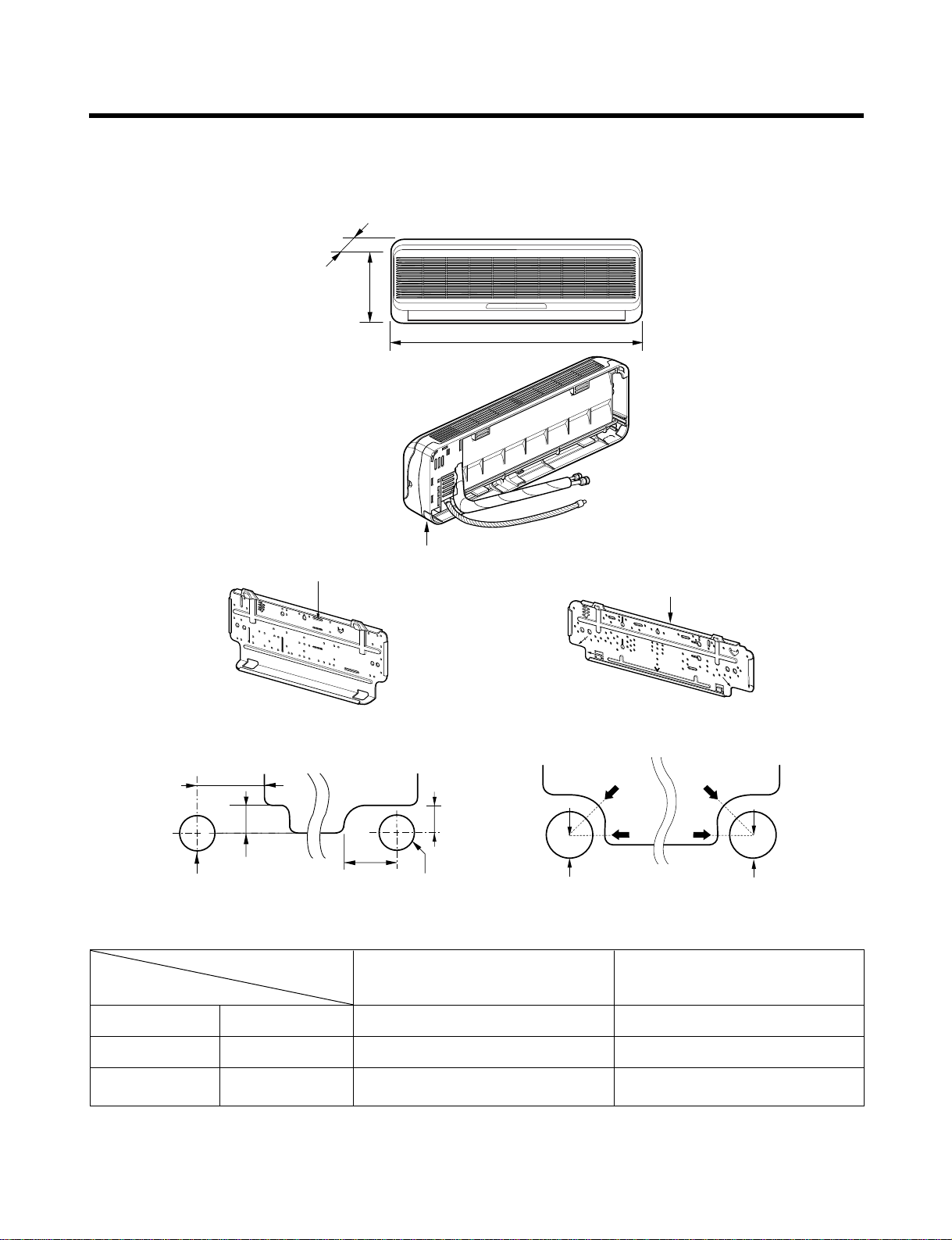
Dimensions
Installation plate
Installation plate
Right rear piping
Left rear piping
ø70mm
ø70mm
50mm
20mm
20mm
80mm
A
A
ø70mm
Center
Center
ø70mm
Left rear piping Right rear piping
A
A
D
H
W
Tubing hole cover
W mm 802 888
H mm 262 287
D mm 165 170
7K Btu Series
14K Btu Series
MODEL
DIM
(7K)
(7K)
(14K)
(14K )
1. Indoor Unit
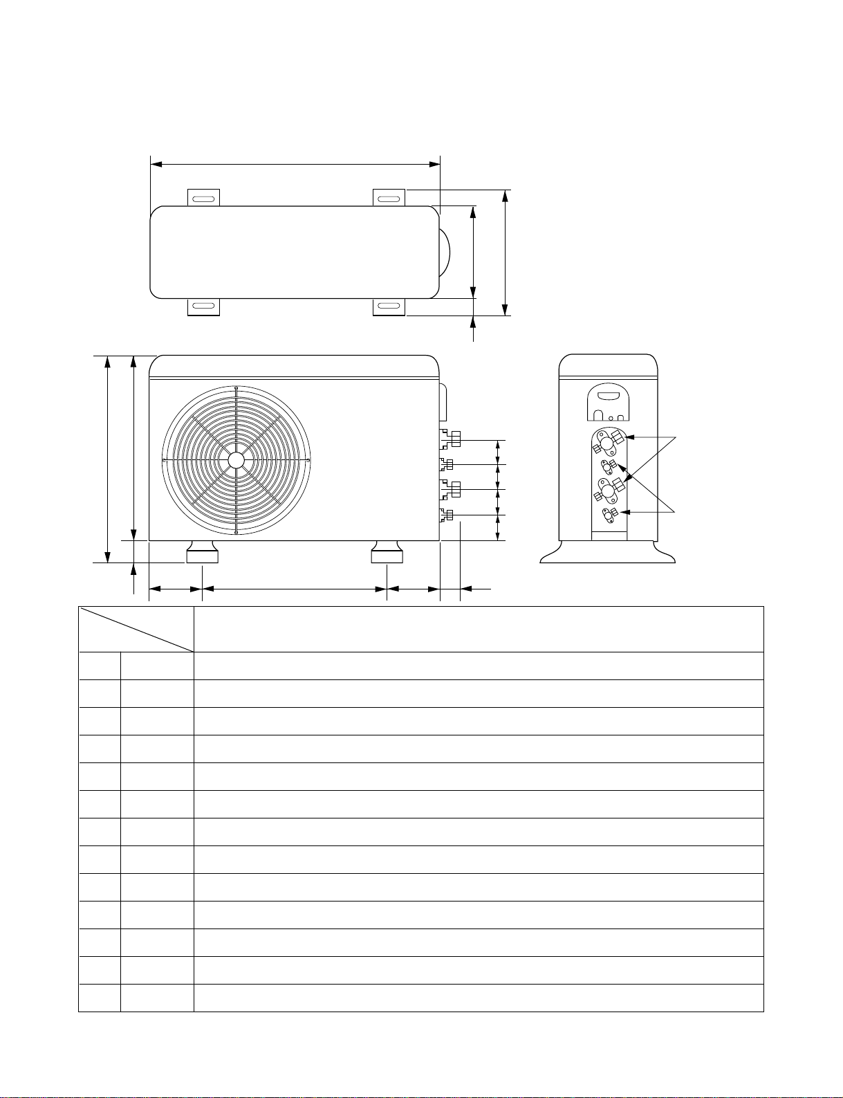
- 8 -
W
D
L1
L2
L9
L4
L3
H
L10
L10
L10
L8
Gas side
3-Way valve
Liquid side
2-Way valve
L7L5L6
2. Outdoor Unit
2-1. LM-2164H2L/M
W mm 870
H mm 655
D mm 320
L1 mm 370
L2 mm 25
L3 mm 630
L4 mm 25
L5 mm 546
L6 mm 160
L7 mm 160
L8 mm 64
L9 mm 76.5
L10 mm 50
LM-2164H2L/M
MODEL
DIM
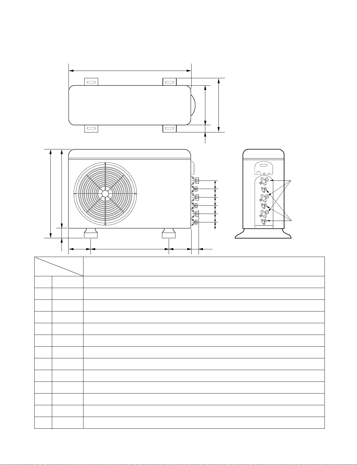
- 9 -
W
L5L6 L7 L8
L3
H
D
L1
L2
L4
L10L9
Gas side
3-way valve
Liquid side
2-way valve
L10L10L10L10
2-2. LM-3064H3L/M
W mm 870
H mm 800
D mm 320
L1 mm 370
L2 mm 25
L3 mm 775
L4 mm 25
L5 mm 546
L6 mm 160
L7 mm 160
L8 mm 64
L9 mm 76.5
L10 mm 50
LM-3064H3L/M
MODEL
DIM
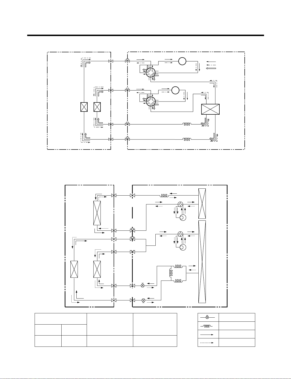
- 10 -
Refrigeration Cycle Diagram
1. LM-2164H2L/M
2. LM-3064H3L/M(Cooling & Heating models)
HEAT
EXCHANGER
COOLING
HEATING
DEICE
HEAT
EXCHANGER
CAPILLARY TUBE
COMPRESSOR-B
COMPRESSOR-A
CAPILLARY TUBE
2-WAY
VALVE
4-WAY
VALVE
B-UNITA-UNIT
3-WAY
VALVE
4-WAY
VALVE
Pipe Size (Diameter : inch)
Max.
piping length
(m)
Max.
piping elevation
(m)
Gas Liquid
3/8"(1/2") 1/4" 10~15 5~7
ex)
Solenoid Valve
Capillary
Cooling & Deice
Heating
Indoor Unit Outdoor Unit
Heat
Exchanger
A-Unit
Heat
Exchanger
Comp-A
B-Unit
C-Unit
Heat
Exchanger
2- WAY
Valve
3- WAY
Valve
2- WAY
Valve
3- WAY
Valve
Comp-B
3854A20023B
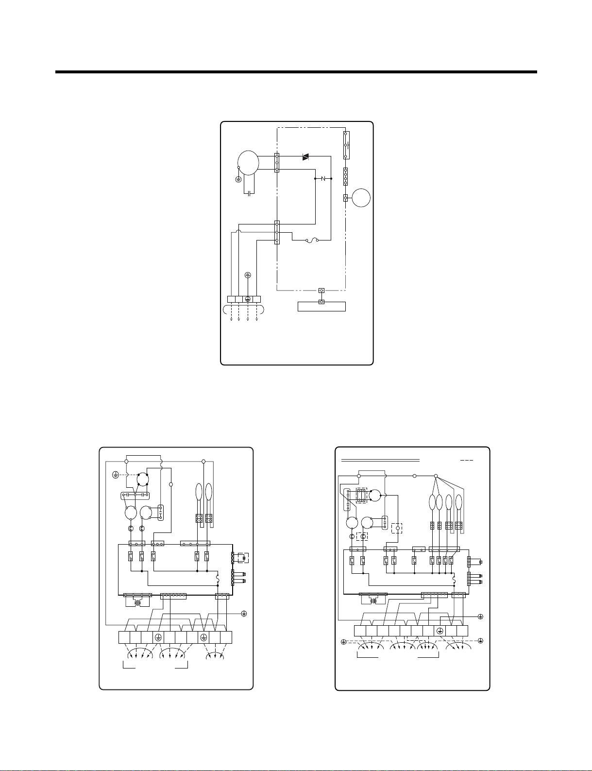
INDOOR WIRING DIAGRAM
CN-DISP1
CN-U/D
FUSE
AC250V/T2A
CN-TH
SSR
SH-CAPA.
BR
YL
OR
BK
CN-POWER CN-FAN
ZNR
THERMISTOR
FORCED
OPERATION
AUTO
RESTART
REMOTE
CONTROL
STEP
MOTOR
MOTOR
MAIN PCB
ASM
DISPLAY PCB ASM
TO OUTDOOR UNIT
PILLAR
TERMINAL
BR
BL
YL
1
(
L
)
2
(
N
)
3
OUTDOOR WIRING DIAGRAM
MOTOR
MAIN PCB ASSY
TO INDOOR UNIT
A-UNIT B-UNIT C-UNIT
MAIN
POWER
TERMINAL
BLOCK
CN-TRANS
BK
BR
BL
BK BK
BK
BK
"A"
COMP
BL
BK
WH RD BL YL
BL BL BK BK
BL BL BK BK
RD
RD
S R
C
OLP
C
R
BR
BK
YL
S
BK
BK
YL
OR
OPTION
BK(Hi)
BK
T/B2 T/B3
OPTION
T/B1
T/B4
7
1 3
1 3
5 3 1 3 1
BK
WH
BK
WH
RD WH BK
GN/YL
CN-COM
CN-TH1 CN-TH2
CN
-
POWER
RY8
RY9
RY3
RY2
RY1
CN
-
FAN CN
-
BYPASSCN
-
COMP
CAPA.
CAPA.
FUSE T3.15A
THERMISTOR
THERMISTOR
TRANS-
FORMER
OLP
OPTION
OPTION
2 1
RY10
RY7
RY5
RY4
"B"
COMP
1(L) 1(L)2(N) 1(L) 2(N)2(N)
3 3 3
H C F
B-S.V
C-S.V
A 4-WAY
B 4-WAY
4 3 2 1
CN-SV
OUTDOOR WIRING DIAGRAM
3854AP3911C
MAIN PCB ASSY
TO INDOOR UNIT
A-UNIT B-UNIT
MAIN
POWER
TERMINAL
BLOCK
CN-TRANS
BK BK
BR
BL
BL YL
BK BK
BK
BK
BK
BK
OR
H C F
YL
BK
BK
"A"
COMP
BL
BK
RD
RD
S R
C
OLP
C
R
BR
BK
YL
S
BK
BK
T/B2
T/B1
T/B3
GN/YL
MOTOR
BK
7
4 33 11 3 2 1
5 3 1 3 1
BK
WH
WH BK
GN/YL
GN/YL
WH
CN-COM
CN-TH1 CN-TH2
CN-POWER
CN-SV
RY9
RY3
RY2
RY1
RY10
CN-FANCN-COMP
CAPA.
CAPA.
FUSE T3.15A
THERMISTOR
THERMISTOR
TRANS-
FORMER
OLP
"B"
COMP
1(L) 1(L)2(N) 1(L) 2(N)2(N)
3 3
A 4-WAY
B 4-WAY
OPTION
- 11 -
Wiring Diagram
1. Indoor Unit
• LM-2164H2L/M
• LM-3064H3L/M
2. Outdoor Unit
• LM-2164H2L/M • LM-3064H3L/M

Operation Details
■ MAIN UNIT FUNCTION
• DISPLAY
1) Cooling Only Model
Operation Indicator
• On while in appliance operation, off while in appliance pause
• Flashing while in disconnection or short in Thermistor (3 sec off / 0.5 sec on)
Sleep Timer Indicator
• On while in sleep timer mode, off when sleep timer cancel or appliance operation pause
Timer Indicator
• On while in timer mode (on/off), off when timer mode is completed or canceled.
Comp. Running Incidator
• While in appliance operation, on while in outdoor unit compressor running, off while in compressor off
2) Heat Pump Model
Operation Indicator
• On while in appliance operation, off while in appliance pause
• Flashing while in disconnection or short in Thermistor (3 sec off / 0.5 sec on)
Sleep Timer Indicator
• On while in sleep timer mode, off when sleep timer cancel or appliance operation pause
Timer Indicator
• On while in timer mode (on/off), off when timer mode is completed or canceled
Defrost Indicator
• Off except when hot start during heating mode operation or while in defrost control
■ Cooling Mode Operation
• When the intake air temperature reaches 0.5°C below the setting temp, the compressor and the outdoor fan
stop.
• When it reaches 0.5°C above the setting temp, they start to operate again.
Compressor ON Temp ➲ Setting Temp+0.5°C
Compressor OFF Temp ➲ Setting Temp-0.5°C
• While in compressor running, operating with the airflow speed set by the remote control. While in compressor
not running, operating with the low airflow speed regardless of the setting.
■ Healthy Dehumidification Mode
• When the dehumidification operation input by the remote control is received, the intake air temperature is
detected and the setting temp is automatically set according to the intake air temperature.
26°C ≤ Intake Air Temp ➲ 25°C
24°C ≤ Intake Intake Air Temp<26°C ➲ Intake Air Temp-1°C
18°C ≤ Intake Intake Air Temp<24°C ➲ Intake Air Temp-0.5°C
Intake Air Temp<18°C ➲ 18°C
-12-

• While in compressor off, the indoor fan repeats low airflow speed and pause.
• While the intake air temp is between compressor on temp. and compressor off temp., 10-min dehumidifica-
tion operation and 4-min compressor off repeat.
Compressor ON Temp. ➲ Setting Temp+0.5°C
Compressor OFF Temp. ➲ Setting Temp-0.5°C
• In 10-min dehumidification operation, the indoor fan operates with the low airflow speed.
■ Heating Mode Operation(Heat Pump models)
• When the intake air temp reaches +3°…above the setting temp, the compressor is turned off. When below
the setting temp, the compressor is turned on.
Compressor ON Temp. ➲ Setting Temp.
Compressor OFF Temp. ➲ Setting Temp.+3°C
• While in compressor on, the indoor fan is off when the indoor pipe temp. is below 20°C, when above 28°C , it
operates with the low or setting airflow speed. When the indoor pipe temp is between 20°C and 28°C, it oper-
ates with Super-Low(while in sleep mode, with the medium airflow speed).
• While in compressor off, the indoor fan is off when the indoor pipe temp is below 33°C, when above 35°C , it
operates with the low airflow speed.
• If overloaded while in heating mode operation, in order to prevent the compressor from OLP operation, the
outdoor fan is turned on/off according to the indoor pipe temp.
• While in defrost control, both of the indoor and outdoor fans are turned off.
■ Defrost Control(Heat Pump models)
• Defrost operation is controlled by timer and sensing temperature of outdoor pipe.
• The first defrost starts only when the outdoor pipe temperature falls below -6°C after 60 minutes passed from
starting of heating operation and more than 10 minutes operation of compressor.
• Defrost ends after 12 minutes passed from starting of defrost operation or after the outdoor fan operates with-
in max. 2 minutes 30 seconds when the outdoor pipe temperature rises over 12°C even it before 12 minutes.
• The second defrost starts only when the outdoor pipe temperature falls below -6°C after 60 minutes passed
from ending of the first defrost and more than 10 minutes operation of compressor.
■ Cooling overload
• Control indoor fan by sensing outdoor pipe temperature.
• One step down from setting fan speed if pipe temperature is oven 50°C and if below 45°C, operate on setting
temperature.
■ Heating overload(Heat Pump models)
• Outdoor fan ON/OFF by sensing outdoor pipe temperature.
• Outdoor fan is OFF if pipe temperature is over 6.5°C and outdoor fan is ON if pipe temperature is below 0°C.
• Outdoor fan is off if any one part is heating overload condition.
-13-

-14-
■ Fuzzy Operation (Cooling Only Model)
• According to the temperature set by Fuzzy rule, when the intake air temp is 0.5°C or more below the setting
temp, the compressor is turned off. When 0.5°C or more above the setting temp, the compressor is turned on.
Compressor ON Temp ➲ Setting Temp + 0.5°C
Compressor OFF Temp ➲ Setting Temp + 0.5°C
• At the beginning of Fuzzy mode operation, the setting temperature is automatically selected according to the
intake air temp at that time.
26°C ≤ Intake Air Temp ➲ 25°C
24°C ≤ Intake Air Temp < 26°C ➲ Intake Air Temp + 1°C
22°C ≤ Intake Air Temp < 24°C ➲ Intake Air Temp + 0.5°C
18°C ≤ Intake Air Temp < 22°C ➲ Intake Air Temp
Intake Air Temp<18°C ➲ 18°C
• When the Fuzzy key (Temperature Control key) is input after the initial setting temperature is selected, the
Fuzzy key value and the intake air temperature at that time are compared to select the setting temperature
automatically according to the Fuzzy rule.
• While in Fuzzy operation, the airflow speed of the indoor fan is automatically selected according to the
temperature.
■ Fuzzy Operation (Heat Pump Models)
• When any of operation mode is not selected like the moment of the power on or when 3 hrs has passed since
the operation off, the operation mode is selected.
• When determining the operation mode, the compressor, the outdoor fan, and the 4 way valve are off and only
the indoor fan is operated for 15 seconds. Then an operation mode is selected according to the intake air
temp at that moment as follows.
24°C ≤ Inatake Air Temp ➲ Fuzzy Operation for Cooling
21°C ≤ Inatake Air Temp<24°C ➲ Fuzzy Operation for Dehumidification
Inatake Air Temp<21°C ➲ Fuzzy Operation for Heating
• If any of the operation modes among cooling / dehumidification / heating mode operations is carried out for 10
sec or longer before Fuzzy operation, the mode before Fuzzy operation is operated.
1) Fuzzy Operation for Cooling
• According to the setting temperature selected by Fuzzy rule, when the intake air temp is 0.5°C or more below
the setting temp, the compressor is turned off. When 0.5°C or more above the setting temp, the compressor
is turned on.
Compressor ON Temp ➲ Setting Temp +0.5°C
Compressor OFF Temp ➲ Setting Temp + 0.5°C
• At the beginning of Fuzzy mode operation, the setting temperature is automatically selected according to the
intake air temp at that time.
26°C≤ Intake Air Temp ➲ 25°C
24°C≤ Intake Air Temp<26°C ➲ Intake Air Temp + 1°C
22°C≤ Intake Air Temp<24°C ➲ Intake Air Temp + 0.5°C
18°C≤ Intake Air Temp<22°C ➲ Intake Air Temp
Intake Air Temp<18°C ➲ 18°C
• When the Fuzzy key (Temperature Control key) is input after the initial setting temperature is selected, the
Fuzzy key value and the intake air temperature at that time are compared to select the setting temperature
automatically according to the Fuzzy rule.
• While in Fuzzy operation, the airflow speed of the indoor fan is automatically selected according to the tem-
perature.

-15-
2) Fuzzy Operation for Dehumidification
• According to the setting temperature selected by Fuzzy rule, when the intake air temp is 0.5°C or more below
the setting temp, the compressor is turned off. When 0.5°C or more above the setting temp, the compressor
is turned on.
Compressor ON Temp ➲ Setting Temp + 0.5°C
Compressor OFF Temp ➲ Setting Temp+0.5°C
• At the beginning of Fuzzy mode operation, the setting temperature is automatically selected according to the
intake air temp at that time.
26°C ≤ Intake Air Temp ➲ 25°C
24°C ≤ Intake Air Temp<26°C ➲ Intake Air Temp+1°C
22°C ≤ Intake Air Temp<24°C ➲ Intake Air Temp+0.5°C
18°C ≤ Intake Air Temp<22°C ➲ Intake Air Temp
Intake Air Temp<18°C ➲ 18°C
• When the Fuzzy key (Temperature Control key) is input after the initial setting temperature is selected, the
Fuzzy key value and the intake air temperature at that time are compared to select the setting temperature
automatically according to the Fuzzy rule.
• While in Fuzzy operation, the airflow speed of the indoor fan repeats the low airflow speed or pause as in
dehumidification operation.
3) Fuzzy Operation for Heating
• According to the setting temperature selected by Fuzzy rule, when the intake air temp is 3°C or more above
the setting temp, the compressor is turned off. When below the setting temp, the compressor is turned on.
Compressor ON Temp ➲ Setting Temp
Compressor OFF Temp ➲ Setting Temp + 3°C
• At the beginning of Fuzzy mode operation, the setting temperature is automatically selected according to the
intake air temp at that time.
20°C≤Intake Air Temp ➲ Intake Air Temp + 0.5°C
Intake Air Temp<20°C ➲ 20°C
• When the Fuzzy key (Temperature Control key) is input after the initial setting temperature is selected, the
Fuzzy key value and the intake air temperature at that time are compared to select the setting temperature
automatically according to the Fuzzy rule.
• While in Fuzzy operation, the airflow speed of the indoor fan is set to the high or the medium according to the
intake air temperature and the setting temperature.
■ Airflow Speed Selection
• The airflow speed of the indoor fan is set to high, medium, low, or chaos (auto) by the input of the airflow
speed selection key on the remote control.
■ On-Timer Operation
• When the set time is reached after the time is input by the remote control, the appliance starts to operate.
• The timer LED is on when the on-timer is input. It is off when the time set by the timer is reached.
• If the appliance is operating at the time set by the timer, the operation continues.

-16-
■ Off-Timer Operation
• When the set time is reached after the time is input by the remote control, the appliance stops operating.
• The timer LED is on when the off-timer is input. It is off when the time set by the timer is reached.
• If the appliance is on pause at the time set by the timer, the pause continues.
■ Off-Timer <=> On-Timer Operation
• When the set time is reached after the on/off time is input by the remote control, the on/off-timer operation is
carried out according to the set time.
■ Sleep Timer Operation
• When the sleep time is reached after <1,2,3,4,5,6,7,0(cancel) hr> is input by the remote control while in appli-
ance operation, the operation of the appliance stops.
• While the appliance is on pause, the sleep timer mode cannot be input.
• While in cooling mode operation, 30 min later since the start of the sleep timer, the setting temperature
increases by 1°C. After another 30 min elapse, it increases by 1°C again.
• When the sleep timer mode is input while in cooling cycle mode, the airflow speed of the indoor fan is set to
the low.
• When the sleep timer mode is input while in heating cycle mode, the airflow speed of the indoor fan is set to
the medium.
■ Chaos Swing Mode
• By the Chaos Swing key input, the upper/lower vane automatically operates with the Chaos Swing or they are
fixed to the desired direction.
• While in Chaos Swing mode, the angles of cooling and heating cycle operations are different.
■ Chaos Natural Wind Mode
• When the Chaos Natural Wind mode is selected and then operated, the high, medium, or low speed of the air-
flow mode is operated for 2~15 sec. randomly by the Chaos Simulation.
■ Jet Cool Mode Operation (Cooling Only Model)
• If the Jet Cool key is input at any operation mode while in appliance operation, the Jet Cool mode operates.
• In the Jet Cool mode, the indoor fan is operated at super-high speed for 30 min at cooling mode operation.
• In the Jet Cool mode operation, the room temperature is controlled to the setting temperature, 18°C
• When the sleep timer mode is input while in the Jet Cool mode operation, the Jet Cool mode has the priority.
• When the Jet Cool key is input, the upper/lower vanes are reset to those of the initial cooling mode and then
operated in order that the air outflow could reach further.
■ Jet Cool Mode Operation (Heat Pump Models)
• While in heating mode or Fuzzy operation, the Jet Cool key cannot be input. When it is input while in the other
mode operation (cooling, dehumidification, ventilation), the Jet Cool mode is operated.
• In the Jet Cool mode, the indoor fan is operated at super-high speed for 30 min at cooling mode operation.
• In the Jet Cool mode operation, the room temperature is controlled to the setting temperature, 18°C.
• When the sleep timer mode is input while in the Jet Cool mode operation, the Jet Cool mode has the priority.
• When the Jet Cool key is input, the upper/lower vanes are reset to those of the initial cooling mode and then
operated in order that the air outflow could reach further.
-17-
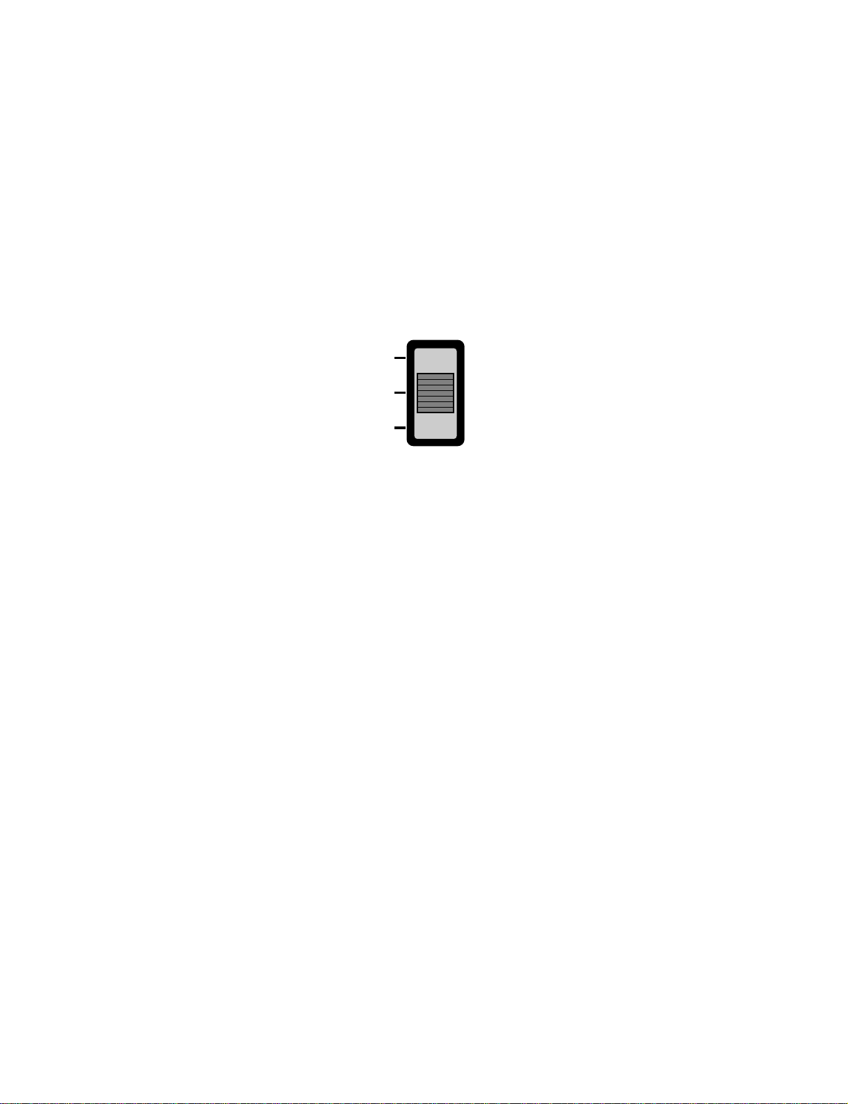
■ Auto Restarting Operation
• When the power is restored after a sudden power failure while in appliance operation, the mode before the
power failure is kept on the memory and the appliance automatically operates in the mode on the memory.
• The slide switch on the main unit of the appliance should be on the Auto Restarting position in order that the
Auto Restarting operation is available.
• Operation Mode that is kept on the memory
- State of Operation ON/OFF
- Operation Mode/Setting Temp/Selected Airflow Speed
- Sleep Timer Mode/Remaining Time of Sleep Timer (unit of hour)
• If no input by the remote control or no switching of the slide switch within 7 hr after the appliance operates by
the Auto Restarting operation, the appliance is forced to stop at the moment of 7-hr elapse.
Slide Switch
FORCED
OPERATION
AUTO
RESTART
REMOTE
CONTROL
■ Forced Operation (Cooling Only Model)
• To operate the appliance by force in case that the remote control is lost, the forced operation selection switch
is on the main unit of the appliance to operate the appliance in the standard conditions.
• When the power is supplied while the slide switch is on the forced operation position, or when the slide switch
position is switched to the Auto Restarting position (or test operation) or switched from the remote control posi-
tion to the forced operation position while the power is on, the forced operation is carried out.
• When the slide switch position is switched from the forced operation position to the Auto Restarting position or
the remote control position, the forced operation is canceled and the appliance stops operating.
• The forced operation is carried out in cooling mode with the setting temperature 22°C and the high speed of
airflow.
• While in forced operation, the key input by the remote control has no effect and the buzzer sounds 10 times to
indicate the forced operation.
■ Forced Operation (Heat Pump Models)
• To operate the appliance by force in case that the remote control is lost, the forced operation selection switch
is on the main unit of the appliance to operate the appliance in the standard conditions.
• When the power is supplied while the slide switch is on the forced operation position, or when the slide switch
position is switched to the Auto Restarting (or test operation) position or switched from the remote control posi-
tion to the forced operation position while the power is on, the forced operation is carried out.
• When the slide switch position is switched from the forced operation position to the Auto Restarting position or
the remote control position, the forced operation is canceled and the appliance stops operating.
•
The forced operation is carried out in cooling mode with the setting temperature 22°C and the high speed of airflow.
• In the forced operation mode, the indoor fan is operated at low speed for around 15 sec and then the operation
condition is set according to the intake air temperature as follows.
24°C≤Intake Air Temp ➲ Cooling Mode Operation, 22°C, High Speed
21°C≤Intake Air Temp<24°C ➲ Dehumidification Operation, 23°C, High Speed
Intake Air Temp<21°C ➲ Heating Mode Operation, 24°C, High Speed

-18-
■ Remote Control Operation Mode
• When the remote control is selected by the slide switch on the main unit, the appliance operates according to
the input by the remote control.
■ Protection of the evaporator pipe from frosting
• If the indoor pipe temp is below 0°C in 7 min. after the compressor operates without any pause while in cool-
ing cycle operation mode, the compressor and the outdoor fan are turned off in order to protect the indoor
evaporator pipe from frosting.
• When the indoor pipe temp is 7°C or higher after 3 min. pause of the compressor, the compressor and the
outdoor fan is turned on according to the condition of the room temperature.
■ Buzzer Sounding Operation
• When the appliance-operation key is input by the remote control, the short "beep-beep-" sounds.
• When the appliance-pause key is input by the remote control, the long "beep—" sounds.
• When a key is input by the remote control while the slide switch on the main unit of the appliance is on the
forced operation position, the error sound "beep-beep-beep-beep-beep-" is made 10 times to indicate that the
remote control signal cannot be received.
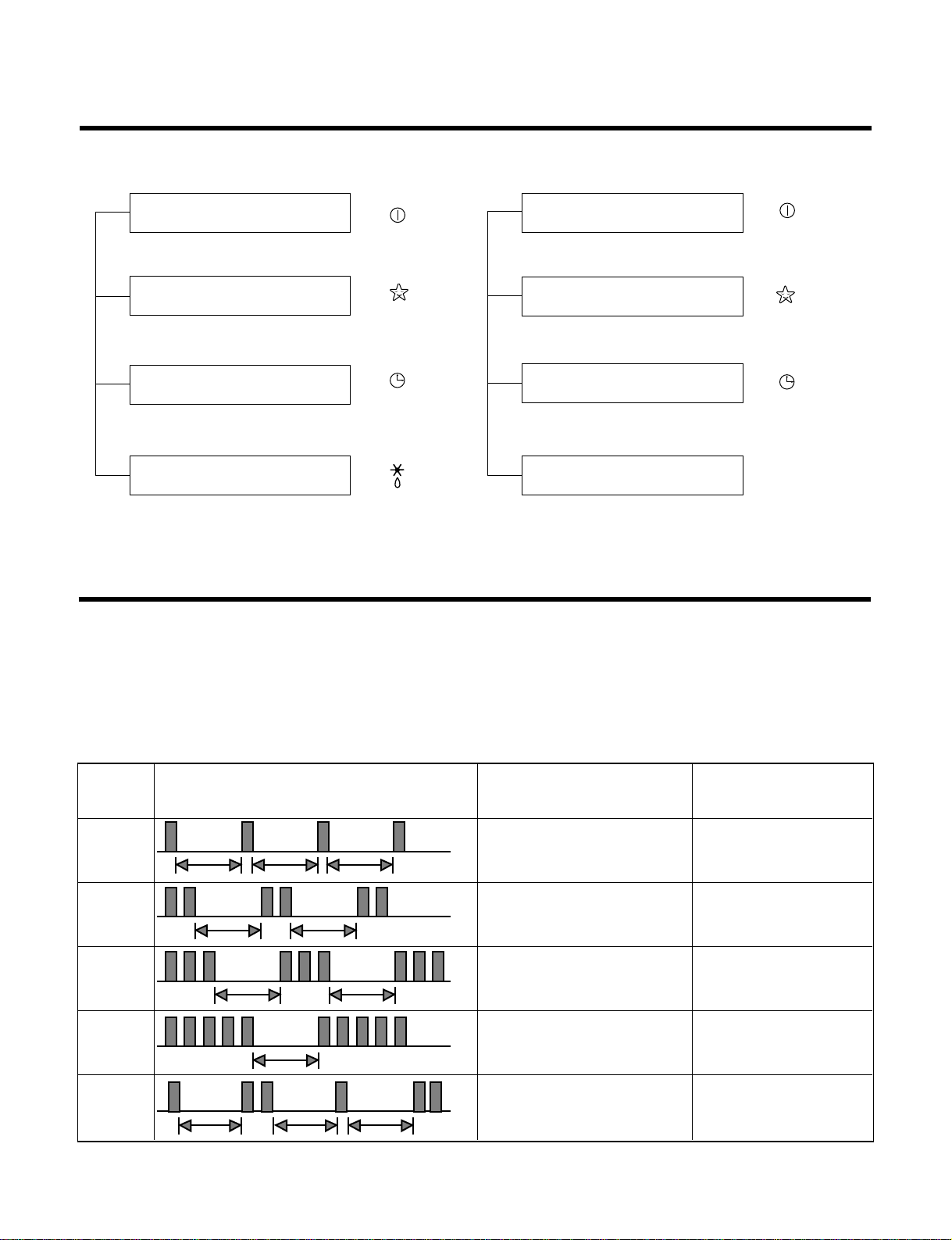
Display Function
1. Heating Model 2. Cooling Model
• Cooling, Soft Dry, Fan, Heating • Cooling, Soft Dry, Fan
• Sleep Mode • Sleep Mode
• Timer Mode • Timer Mode
• Hot-start, Defrost
Self-diagnosis Function
■ Error Indicator
• The function is to self-diagnoisis airconditioner and express the troubles identifically if there is any trouble.
• Error mark is ON/OFF for the operation LED of evaporator body in the same manner as the following table.
• If more than two troubles occur simultaneously, primarily the highest trouble fo error code is expressed.
• After error occurrence, if error is released, error LED is also released simultaneously.
• To operate again on the occurrence of error code 12, be sure to pull out power cord and then re-insert.
• Having or not of error code is different from Model.
Operation Indicator
Timer Indicator
Sleep Timer Indicator
Defrost Indicator
-19-
Operation Indicator
Timer Indicator
Sleep Timer Indicator
Compressor on Indicator
OUT
DOOR
1
(once)
(once)
(twice)
(twice)
(5times)
(once)
(twice)
(3times)
3sec 3sec
3sec
3sec 3sec
3sec
3sec
3sec 3sec
3sec
3sec
2
3
5
12
Error
Code
Error LED
(Indoor body operation LED)
Error contents SVC check point
• Indoor suction temperature
thermistor open/short.
• Indoor pipe temperature
thermistor open/short.
• Indoor TH ass'y check
• Outdoor TH ass'y
check
• Resetting of remocon
operating mode
• Communication
line/circuit check
• Primarily check
refrigerant pressure
• Connecting pipe check
• Connecting cable check
• Outdoor suction temperature
thermistor open/short.
• Outdoor pipe temperature
thermistor open/short.
• Abnormal operation of multi
product.
(Simultanueous operation of
cooling and heating)
• Misconnection of connecting
cables
• Poor communication
- 20 -
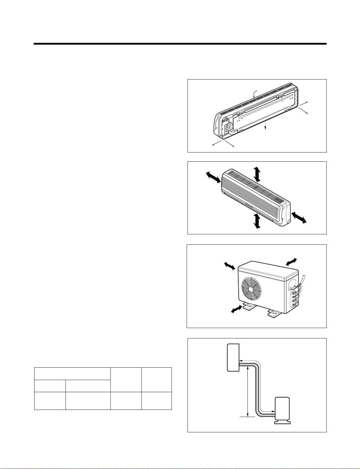
Installation
Front
Right Rear right
Rear left
Down right
Left
More than 5 cm
More than eye-level
More than
5 cm
More than
5 cm
More than 10 cm
More than 10 cm
More than 70 cm
A
B
Indoor unit
Outdoor unit
1) Selection of the best location
1. Indoor unit
• There should not be any heat source or steam
near the unit.
• There should not be any obstacles to prevent
the air circulation.
• A place where air circulation in the room will be
good.
• A place where drainage can be easily obtained.
• A place where noise prevention is taken into
consideration.
• Do not install the unit near the door way.
• Ensure the spaces indicated by arrows from
the wall, ceiling, fence, or other obstacles.
2. Outdoor unit
• If an awning is built over the unit to prevent
direct sunlight or rain exposure, be careful that
heat radiation from the condenser is not
restricted.
• There should not be any animals or plants
which could be affected by hot air discharged.
• Ensure the spaces indicated by arrows from
the wall, ceiling, fence, or other obstacles.
3. Piping length and the elevation
Pipe Size
GAS LIQUID
Max. piping
length
A (m)
Max.
Elevation
B (m)
1/2"(3/8") 1/4" 10~15 5~7
(1) Installation of Indoor, Outdoor unit
 Loading...