


LHN367HV
Table of contents
 Loading...
DUCTED INDOOR UNITS
INSTALLATION MANUAL
High-Static Ducted Indoor Units
ARNU073BGA4
ARNU093BGA4
ARNU123BGA4
ARNU153BGA4
ARNU183BGA4
ARNU243BGA4
ARNU283BGA4
ARNU363BGA4
ARNU423BGA4
ARNU283BRA4
ARNU363BRA4
ARNU423BRA4
ARNU483BRA4
ARNU543BRA4
ARNU363B8A4
ARNU423B8A4
ARNU483B8A4
ARNU763B8A4
ARNU963B8A4
ARNU073BHA4
ARNU093BHA4
ARNU123BHA4
ARNU153BHA4
ARNU183BHA4
ARNU243BHA4
Built-In Ducted Indoor Units
ARNU073B3G4
ARNU093B3G4
ARNU123B3G4
ARNU153B3G4
ARNU183B4G4
ARNU243B4G4
Vertical Air Handler
Indoor Units
ARNU123NJA4
ARNU183NJA4
ARNU243NJA4
ARNU303NJA4
ARNU363NJA4
ARNU423NKA4
ARNU483NKA4
ARNU543NKA4
Low-Static Ducted Indoor Units
ARNU073L1G4
ARNU093L1G4
ARNU123L2G4
ARNU153L2G4
ARNU183L2G4
ARNU243L3G4

The instructions included in this manual must be followed to prevent prod-
uct malfunction, property damage, injury, or death to the user or other
people. Incorrect operation due to ignoring any instructions will cause
harm or damage. A summary of safety precautions begins on page 4.
Do not throw away, destroy, or lose this manual.
Please read carefully and store in a safe place for future reference.
Content familiarity required for proper installation.
For more technical materials such as submittals, engineering
databooks, and catalogs, visit www.lghvac.com.
For continual product development, LG Electronics U.S.A., Inc., reserves the right to change specifications without notice.
©LG Electronics U.S.A., Inc.
This document, as well as all reports, illustrations, data, information, and other materials are the property of LG Electronics U.S.A., Inc.
PROPRIETARY DATA NOTICE
This document, as well as all reports, illustrations, data, information, and other
materials are the property of LG Electronics U.S.A., Inc., and are
disclosed by LG Electronics U.S.A., Inc., only in confidence.
IM_MultiV_Ducted_IDU_5_16
3
Installation Manual
Due to our policy of continuous product innovation, some specifications may change without notification.
©LG Electronics U.S.A., Inc., Englewood Cliffs, NJ. All rights reserved. “LG” is a registered trademark of LG Corp.
TABLE OF CONTENTS
Safety Instructions .........................................................................4
Introduction ....................................................................................9
Unit Nomenclature ....................................................................... 11
R410A Refrigerant .......................................................................12
General Data ...............................................................................13
Specications − High-Static BH Chassis ........................................... 13
Specications − High-Static BG Chassis ........................................... 14
Specications − High-Static BG Chassis ........................................... 15
Specications − High-Static BR/B8 Chassis...................................... 16
Specications − Low-Static B3/B4 Chassis ....................................... 18
Specications − Low-Static Ducted L1/L2/L3 Chassis ...................... 19
Specications − Vertical Air Handler NJ Chassis ............................... 20
Specications − Vertical Air Handler NK Chassis .............................. 21
Electrical − High-Static BH/BG/BR/B8 Chassis ................................. 22
Electrical − Low-Static Built-In B3/B4 Chassis .................................. 23
Electrical − Low-Static Ducted L1/L2/L3 Chassis .............................. 24
Dimensions – High-Static Ducted BH Chassis .................................. 25
Dimensions – High-Static Ducted BG Chassis .................................. 26
Dimensions – High-Static Ducted BR Chassis .................................. 27
Dimensions – High-Static Ducted B8 Chassis ................................... 28
Dimensions – Built-In Low-Static Ducted B3/B4 Chassis .................. 29
Dimensions – Low-Static Ducted L1/L2/L3 Chassis .......................... 30
Dimensions – Vertical Air Handler NJ Chassis .................................. 31
Dimensions – Vertical Air Handler NK Chassis.................................. 32
Refrigerant Piping Diagrams ............................................................. 33
General Installation Guidelines ....................................................34
Installation ...................................................................................35
Install Ducted IDU Chassis ................................................................ 35
Indoor Unit Dimensions ..................................................................... 36
Duct Connection Dimensions ............................................................ 37
Maintenance Clearances ................................................................... 38
Piping Connections ............................................................................ 39
Refrigerant Piping ........................................................................40
Condensate Piping ......................................................................44
Power and Control Wiring ............................................................46
Overview ............................................................................................ 46
Indoor Unit Communication Cable Connections ................................ 47
Indoor Unit Power Cable Connections .............................................. 50
DIP Switch Settings for Gen4 Equipment .......................................... 52
High-Static Ducted BH Chassis ......................................................... 53
High-Static Ducted BG Chassis ......................................................... 55
High-Static Ducted BR Chassis ......................................................... 57
High-Static Ducted B8 Chassis ......................................................... 59
Low-Static Ducted L1 Chassis ........................................................... 61
Low-Static Ducted L2/L3 Chassis ...................................................... 63
Low-Static Built-In B3/B4 Chassis ..................................................... 65
Vertical Air Handler NJ Chassis ......................................................... 67
Vertical Air Handler NK Chassis ........................................................ 69
Optional Wall-Mounted Sensor and Controller .................................. 71
Controls Setup .............................................................................72
Installation Checklist .................................................................... 76
4
Multi V Ducted Indoor Units
Due to our policy of continuous product innovation, some specifications may change without notification.
©LG Electronics U.S.A., Inc., Englewood Cliffs, NJ. All rights reserved. “LG” is a registered trademark of LG Corp.
SAFETY INSTRUCTIONS
The instructions below must be followed to prevent product malfunction, property damage, injury or death to the user or other people. Incor-
rect operation due to ignoring any instructions will cause harm or damage. The level of seriousness is classified by the symbols below.
WARNING
Do not install, remove, or re-install the unit by yourself
(end-user). Ask the dealer or an an LG trained service
provider to install the unit.
Improper installation by the user may result in water leakage, re,
explosion, electric shock, physical injury or death.
For replacement of an installed unit, always contact an
LG trained service provider.
There is risk of re, electric shock, explosion, and physical injury or death.
The outdoor unit is shipped with refrigerant and the service
valves closed. Do not open service valves on the unit until
all non-condensibles have been removed from the piping
system and authorization has been obtained from the com-
missioning agent.
There is a risk of physical injury or death.
Do not run the compressor with the service valves
closed.
There is risk of explosion, physical injury, or death.
Periodically check that the outdoor unit is not damaged.
There is risk of explosion, physical injury, or death.
Replace all control box and panel covers.
If cover panels are not installed securely, dust, water and animals may
enter the unit, causing re, electric shock, and physical injury or death.
Always check for system refrigerant leaks after the unit has
been installed or serviced.
Exposure to high concentration levels of refrigerant gas may lead to
illness or death.
Do not install the unit using defective hanging, attaching,
or mounting hardware.
There is risk of physical injury or death.
Wear protective gloves when handling equipment.
Sharp edges may cause personal injury.
Dispose of the packing materials safely.
• Packing materials, such as nails and other metal or wooden parts
may cause puncture wounds or other injuries.
• Tear apart and throw away plastic packaging bags so that children
may not play with them and risk suffocation and death.
Do not install the unit in any location exposed to open
ame or extreme heat. Do not touch the unit with wet hands.
There is risk of re, electric shock, explosion, and physical injury or death.
Install the unit considering the potential for earthquakes.
Improper installation may cause the unit to fall, resulting in physical
injury or death.
Do not change the settings of the protection devices.
If the pressure switch, thermal switch, or other protection device is
shorted and forced to operate improperly, or parts other than those
specied by LG are used, there is risk of re, electric shock, explosion,
and physical injury or death.
If the air conditioner is installed in a small space, take mea-
sures to prevent the refrigerant concentration from exceed-
ing safety limits in the event of a refrigerant leak.
Consult the latest edition of ASHRAE (American Society of Heating,
Refrigerating, and Air Conditioning Engineers) Standard 15. If the re-
frigerant leaks and safety limits are exceeded, it could result in personal
DANGER
This symbol indicates an imminently hazardous situation which, if not avoided, will result in death or
serious injury.
WARNING
This symbol indicates a potentially hazardous situation which, if not avoided, could result in death or
serious injury.
CAUTION
This symbol indicates a potentially hazardous situation which, if not avoided, may result in minor or
moderate injury.
Note:
This symbol Indicates situations that may result in equipment or property damage accidents only.
This symbol indicates an action that should not be performed.
TABLE OF SYMBOLS
INSTALLATION
DANGER
Don’t use or store ammable gas or combustibles near the unit.
There is risk of re, explosion, and physical injury or death.

5
Installation Manual
Due to our policy of continuous product innovation, some specifications may change without notification.
©LG Electronics U.S.A., Inc., Englewood Cliffs, NJ. All rights reserved. “LG” is a registered trademark of LG Corp.
SAFETY INSTRUCTIONS
injuries or death from oxygen depletion.
CAUTION
Be very careful when transporting the product.
• Do not attempt to carry the product without assistance.
• Some products use polypropylene bands for packaging. Do not use polypropylene bands to lift the unit.
• Suspend the unit from the base at specified positions.
• Support the unit at a minimum of four points to avoid slippage from rigging apparatus.
• Failure to follow these directions may result in minor or moderate physical injury.
INSTALLATION – CONTINUED
Note:
Properly insulate all cold surfaces to prevent “sweating.”
Cold surfaces such as uninsulated pipe can generate condensate that
may drip and cause a slippery oor condition and/or water damage to
walls.
When installing the unit in a hospital, mechanical room, or
similar electromagnetic eld (EMF) sensitive environment,
provide sufcient protection against electrical noise.
Inverter equipment, power generators, high-frequency medical equip-
ment, or radio communication equipment may cause the air conditioner to
operate improperly. The unit may also affect such equipment by creating
electrical noise that disturbs medical treatment or image broadcasting.
Do not use the product for special purposes such as pre-
serving foods, works of art, wine coolers, or other precision
air conditioning applications. This equipment is designed to
provide comfort cooling and heating.
There is risk of property damage.
Do not make refrigerant substitutions. Use R410A only.
If a different refrigerant is used, or air mixes with original refrigerant, the
unit will malfunction and become damaged.
Do not install the unit in a noise sensitive area.
When connecting refrigerant tubing, remember to allow for
pipe expansion.
Improper piping may cause refrigerant leaks and system malfunction.
Take appropriate actions at the end of HVAC equipment life
to recover, recycle, reclaim or destroy R410A refrigerant ac-
cording to applicable U.S. Environmental Protection Agency
(EPA) rules.
Periodically check that the outdoor unit is not damaged.
There is a risk of equipment damage.
Install the unit in a safe location where no one can step on or
fall onto it.
Do not install the unit with defective hanging,
attaching, or mounting hardware.
There is risk of unit and property damage.
Install the drain hose to ensure adequate drainage.
There is a risk of water leakage and property damage.
Don’t store or use ammable gas/combustibles near the
unit.
There is risk of product failure.
Always check for system refrigerant leaks after the unit has
been installed or serviced.
Low refrigerant levels may cause product failure
The unit is shipped with refrigerant and the service valves
closed.
Do not open service valves on the unit until all
non-condensibles have been removed from the piping sys-
tem and authorization to do so has been obtained from the
com-missioning agent.
There is a risk of refrigerant contamination, refrigerant loss and equip-
ment damage.
6
Multi V Ducted Indoor Units
Due to our policy of continuous product innovation, some specifications may change without notification.
©LG Electronics U.S.A., Inc., Englewood Cliffs, NJ. All rights reserved. “LG” is a registered trademark of LG Corp.
SAFETY INSTRUCTIONS
WIRING
DANGER
High voltage electricity is required to operate this system.
Adhere to the National Electrical Codes and these
instructions when wiring.
Improper connections and inadequate grounding can cause accidental
injury or death.
Always ground the unit following local, state, and National
Electrical Codes.
Turn the power off at the nearest disconnect before servicing
the equipment.
Electric shock can cause physical injury or death.
Properly size all circuit breakers or fuses.
There is risk of re, electric shock, explosion, physical injury or death.
WARNING
The information contained in this manual is intended for use
by an industry-qualied, experienced, trained electrician
familiar with the U.S. National Electric Code (NEC) who is
equipped with the proper tools and test instruments.
Failure to carefully read and follow all instructions in this manual can
result in equipment malfunction, property damage, personal injury or
death.
Ensure the unit is connected to a dedicated power source
that provides adequate power.
If the power source capacity is inadequate or the electric work is not per-
formed properly, it may result in re, electric shock, physical injury or death.
Refer to local, state, and federal codes, and use power wires
of sufcient current capacity and rating.
Wires that are too small may generate heat and cause a re.
Secure all eld wiring connections with appropriate wire
strain relief.
Improperly securing wires will create undue stress on equipment power
lugs. Inadequate connections may generate heat, cause a re and
physical injury or death.
Properly tighten all power connections.
Loose wiring may overheat at connection points, causing a re, physical
injury or death.
Note:
Do not cut, lengthen or shorten the communications and
power cable between any dry contact unit and its connected
indoor unit. Do not install the unit in a location where the com-
munications and power cable cannot be safely and easily con-
nected between the two units. Do not allow strain on this cable.
Poor cable connections can cause equipment malfunction.
7
Installation Manual
Due to our policy of continuous product innovation, some specifications may change without notification.
©LG Electronics U.S.A., Inc., Englewood Cliffs, NJ. All rights reserved. “LG” is a registered trademark of LG Corp.
OPERATION
DANGER
Do not provide power to or operate the unit if it is ooded
or submerged.
There is risk of re, electric shock, physical injury or death.
Use a dedicated power source for this product.
There is risk of re, electric shock, physical injury or death.
Do not operate the disconnect switch with wet hands.
There is risk of re, electric shock, physical injury or death.
Periodically verify the hanging bolts and other hardware
securing the unit have not deteriorated.
If the unit falls from its installed location, it can cause property damage,
product failure, physical injury or death.
If refrigerant gas leaks out, ventilate the area before operat-
ing the unit.
If the unit is mounted in an enclosed, low-lying, or poorly ventilated area
and the system develops a refrigerant leak, it may cause re, electric
shock, explosion, physical injury or death.
Note:
Clean up the site after installation is nished, and check
that no metal scraps, screws, or bits of wiring have been left
inside or surrounding the unit.
Do not use this equipment in mission critical or special-
purpose applications such as preserving foods, works of art,
wine coolers or refrigeration. This equipment is designed to
provide comfort cooling and heating.
Provide power to the compressor crankcase heaters at least
six (6) hours before operation begins.
Starting operation with a cold compressor sump(s) may result in severe
bearing damage to the compressor(s). Keep the power switch on during
the operational season.
Do not block the inlet or outlet.
Unit may malfunction.
Securely attach the electrical cover to the indoor unit. Non-
secured covers can result in re due to dust or water in the
service panel.
Periodically verify the equipment mounts have not deterio-
rated.
If the base collapses, the unit could fall and cause property damage or
product failure.
Do not allow water, dirt, or animals to enter the unit.
There is risk of unit failure.
WARNING
Do not allow water, dirt, or animals to enter the unit.
There is risk of unit failure, re, electric shock, physical injury or death.
Avoid excessive cooling and periodically perform ventilation
to the unit.
Inadequate ventilation is a health hazard.
Do not touch refrigerant piping during or after operation.
It can cause burns or frostbite.
Do not operate the unit with the panel(s) or protective
cover(s) removed; keep ngers and clothing away from
moving parts.
The rotating, hot, cold, and high-voltage parts of the unit can cause
physical injury or death.
Periodically check power cable and connection for damage.
Cable must be replaced by the manufacturer, its service agent, or similar
qualied persons in order to avoid physical injury and/or electric shock.
Securely attach the electrical cover to the unit.
Non-secured electrical covers can result in burns or electric shock due to
dust or water in the service panel.
Do not open the inlet grille of the unit during operation.
Do not operate the unit with the panels or guards removed.
Do not insert hands or other objects through the inlet or
outlet when the unit is powered. Do not touch the electro-
static lter, if the unit includes one. The unit contains sharp,
rotating, hot, and high voltage parts that can cause personal
injury and/or electric shock.
Ensure no power is connected to the unit other than as
directed in this manual. Remove power from the unit before
removing or servicing the unit.
There is risk of unit failure, re, electric shock, physical injury or death.
Do not open the inlet grille of the unit during operation.
Do not operate the unit with the panels or guards removed.
Do not insert hands or other objects through the inlet or out-
let with the unit is plugged in. Do not touch the electrostatic
lter, if the unit includes one.
The unit contains sharp, rotating, hot, and high voltage parts that can
cause personal injury and/or electric shock.
CAUTION
To avoid physical injury, use caution when cleaning or
servicing the air conditioner.

8
Multi V Ducted Indoor Units
Due to our policy of continuous product innovation, some specifications may change without notification.
©LG Electronics U.S.A., Inc., Englewood Cliffs, NJ. All rights reserved. “LG” is a registered trademark of LG Corp.
9
Installation Manual
Due to our policy of continuous product innovation, some specifications may change without notification.
©LG Electronics U.S.A., Inc., Englewood Cliffs, NJ. All rights reserved. “LG” is a registered trademark of LG Corp.
INTRODUCTION
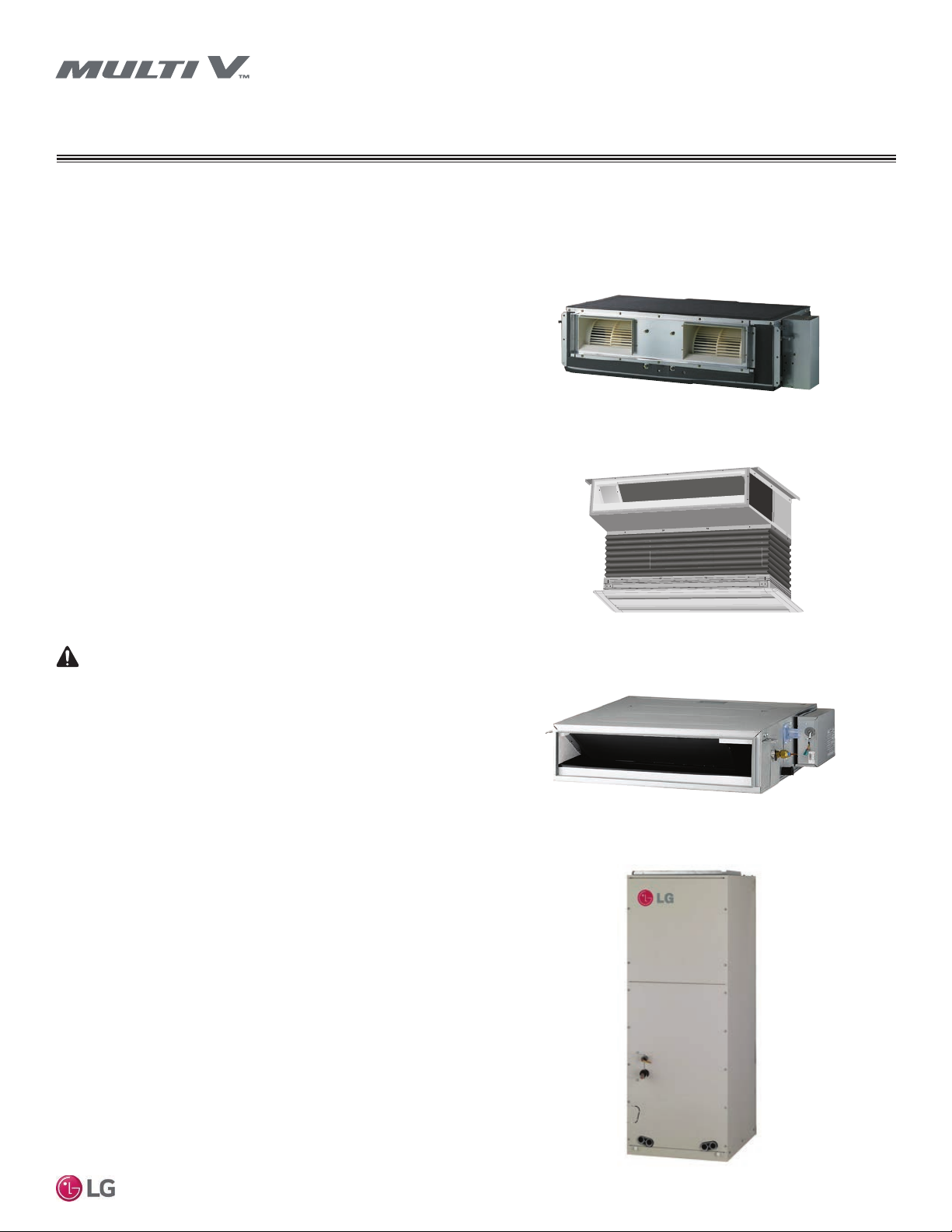
Ducted Indoor Units
This manual describes how to install LG ducted indoor units (IDU)
for Multi V Variable Refrigerant Flow (VRF) heat pump and heat
recovery systems. Table 1 lists the available models. Refer to LG’s
Multi V Indoor Unit Engineering Manual for complete detailed
engineering data and selection procedures.
Safety
Safety of personnel is the primary concern during all procedures.
Read and understand the safety summary at the front of this manual.
Read and understand this installation procedure before beginning
installation. Use the appropriate tools and accessories during instal-
lation. Plan your work and do not work alone, if possible. Know how
to obtain emergency medical and fire fighting assistance.
Installation Personnel
This equipment is intended for installation by personnel trained
in the required construction, mechanical, electrical, and/or other
disciplines.
Applicable Codes
Personnel must be familiar with and follow the applicable national,
state, and/or local codes.
• Pipes - vapor line and liquid line, with insulation
• 3/8” or 1/2” nuts, at washers, and lock/split washers
• 3/8” or 1/2” threaded hanger rods
• Insulated drain hose
• Additional drain hose
• Connecting cable (power and control)
• Level
• Screwdriver
• Electrical lineman pliers
• Electric drill
• Holesaw
• Drill
• Flaring tool set
• Tubing cutter
• Tube/pipe reamer
• Torque wrenches
• Allen wrench
• Gas-leak detector
• Thermometer
WARNING
Installation work must be performed by trained personnel and in ac-
cordance with national wiring standards and all local or other applicable
codes. Improper installation can result in re, electric shock, physical
injury, or death.
Note:
Please read all instructions before installing this product. Become familiar
with the unit, its components and connections, and the order of installa-
tion. Incorrect installation can degrade or prevent proper operation.
Figure 1: High-Static Ducted, BG/BR/B8/BH Chassis
Figure 2: Built-In Ducted, B3/B4 Chassis
Figure 3: Low-Static Ducted, L1/L2/L3 Chassis
Required Tools (field provided)
Required Parts (field provided)
Figure 4: Vertical Air Handler NJ/NK Chassis
10
Multi V Ducted Indoor Units
Due to our policy of continuous product innovation, some specifications may change without notification.
©LG Electronics U.S.A., Inc., Englewood Cliffs, NJ. All rights reserved. “LG” is a registered trademark of LG Corp.
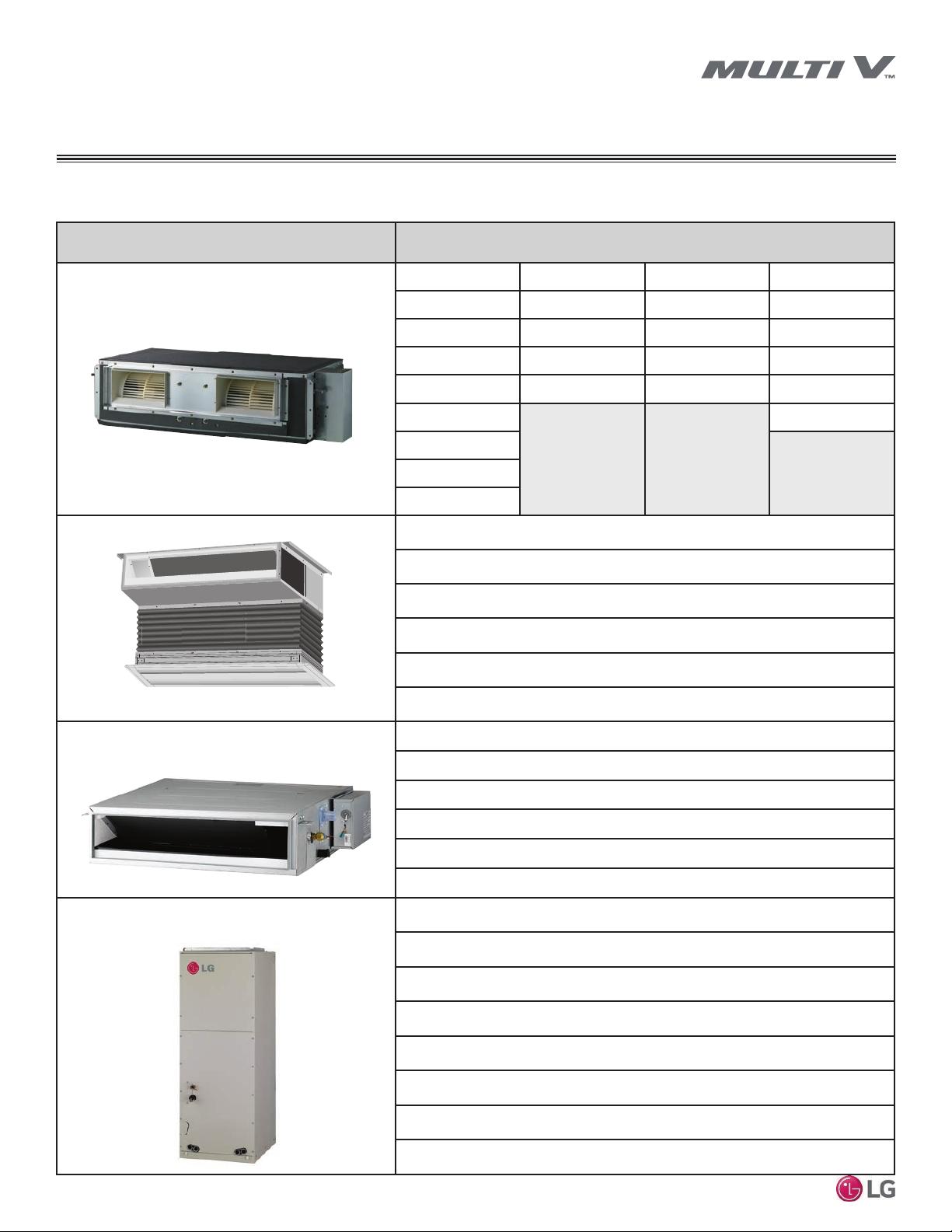
Unit Model Numbers
High-Static Ducted BG/BR/B8
ARNU073BGA4 ARNU283BRA4 ARNU363B8A4 ARNU073BHA4
ARNU093BGA4 ARNU363BRA4 ARNU423B8A4 ARNU093BHA4
ARNU123BGA4 ARNU423BRA4 ARNU483B8A4 ARNU123BHA4
ARNU153BGA4 ARNU483BRA4 ARNU763B8A4 ARNU153BHA4
ARNU183BGA4 ARNU543BRA4 ARNU963B8A4 ARNU183BHA4
ARNU243BGA4 ARNU243BHA4
ARNU283BGA4
ARNU363BGA4
ARNU423BGA4
Built-In Ducted B3/B4
(shown with optional canvas boot and grill)
ARNU073B3G4
ARNU093B3G4
ARNU123B3G4
ARNU153B3G4
ARNU183B4G4
ARNU243B4G4
Low-Static Ducted L1/L2/L3
ARNU073L1G4
ARNU093L1G4
ARNU123L2G4
ARNU153L2G4
ARNU183L2G4
ARNU243L3G4
Vertical Air Handler
ARNU123NJA4
ARNU183NJA4
ARNU243NJA4
ARNU303NJA4
ARNU633NJA4
ARNU423NKA4
ARNU483NKA4
ARNU543NKA4
Table 1: Multi V Ducted Indoor Units
INTRODUCTION
11
Installation Manual
Due to our policy of continuous product innovation, some specifications may change without notification.
©LG Electronics U.S.A., Inc., Englewood Cliffs, NJ. All rights reserved. “LG” is a registered trademark of LG Corp.
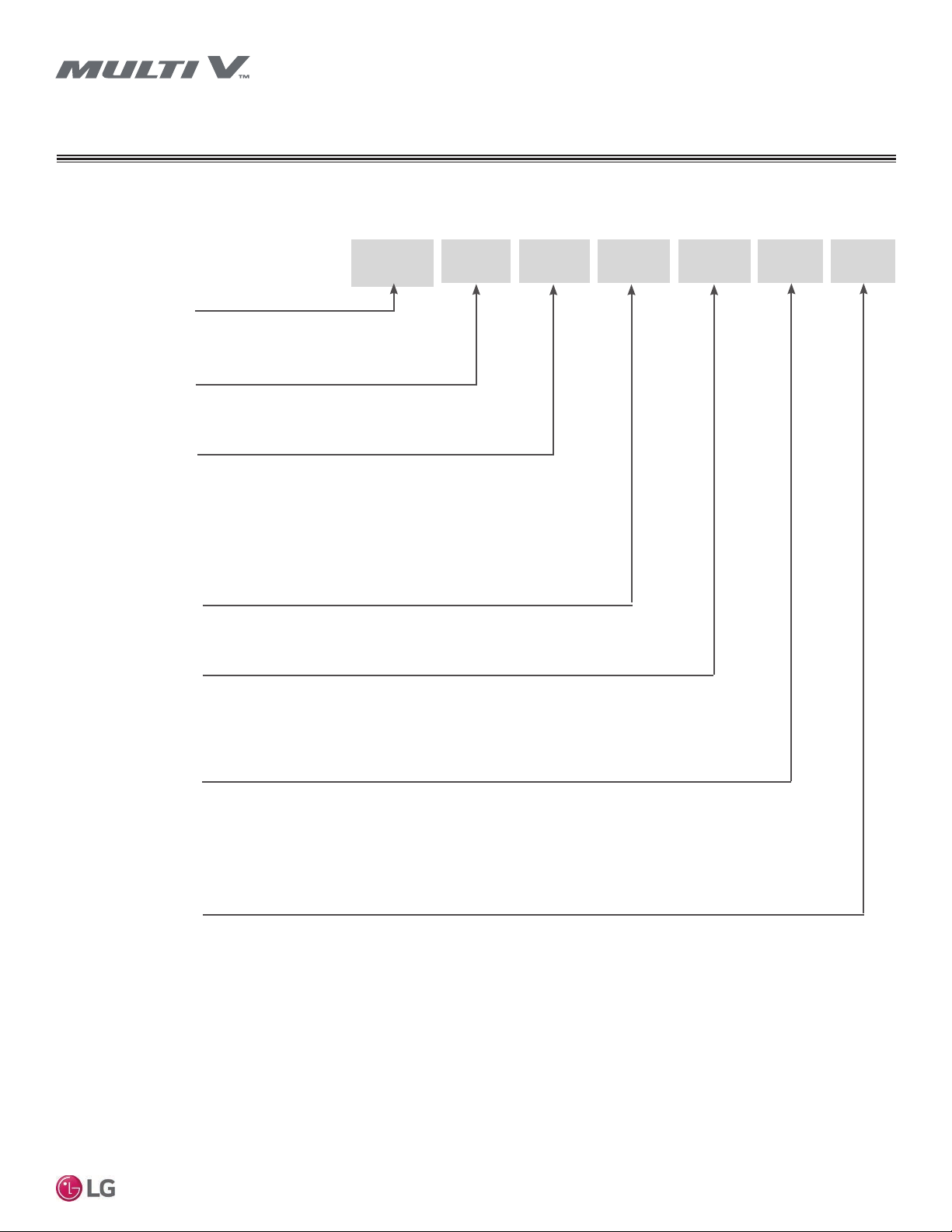
Cassette Indoor Units Nomenclature
ARN
U 07 3 BG A
Generation
4 = Fourth
BG = High-Static Ducted
BR = High-Static Ducted
B8 = High-Static Ducted
B3 = Built-In Ducted
B4 = Built-In Ducted
BH = Built-In Ducted
L1 = Low-Static Ducted
L2 = Low-Static Ducted
L3 = Low-Static Ducted
NJ = Vertical Air Handler
NK = Vertical Air Handler
Electrical Ratings
3 = 208–230V/60Hz/1Phase
Nominal Capacity
(Nominal cooling capacity in Btu/h)
Type
U = Inverter Heat Pump/Heat Recovery
Family
ARN = Multi V Indoor Unit (Refrigerant R410A)
4
Feature
C = Plasma Filter
A = No Plasma Filter
G = Low-Static
07 = 7,500
09 = 9,600
12 = 12,300
15 = 15,400
18 = 19,100
24 = 24,200
28 = 28,000
36 = 36,200
42 = 42,000
48 = 48,000
54 = 54,000
76 = 76,000
96 = 96,000
UNIT NOMENCLATURE
Chassis/Model Type
12
Multi V Ducted Indoor Units
Due to our policy of continuous product innovation, some specifications may change without notification.
©LG Electronics U.S.A., Inc., Englewood Cliffs, NJ. All rights reserved. “LG” is a registered trademark of LG Corp.
R410A REFRIGERANT
R410A refrigerant has a higher operating pressure in comparison to R22 refrigerant and, therefore, all piping system materials
installed must have a higher resisting pressure than the materials traditionally used in R22 systems.
R410A refrigerant is an azeotrope of R32 and R125, mixed at 50:50, so the ozone depletion potential (ODP) is 0.
WARNING
• Do not place the refrigerant cylinder in direct sunlight. Refrigerant cylinder may explode causing severe injury or death.
Note:
• Because R410A is a combination of R32 and R125, the required additional refrigerant must be charged in its liquid state. If the
refrigerant is charged in its gaseous state, its composition changes and the system will not work properly.
• Do not heat piping more than necessary during installation. Piping may become soft and fail when pressurized.
• Do not use any piping that has not been approved for use in high-pressure refrigerant systems. Piping wall thickness must comply
with the applicable local, state, and federal codes for the 551 psi design pressure of R410A. Inadequate piping may fail when
pressurized.

13
Installation Manual
Due to our policy of continuous product innovation, some specifications may change without notification.
©LG Electronics U.S.A., Inc., Englewood Cliffs, NJ. All rights reserved. “LG” is a registered trademark of LG Corp.
1
Power Input is rated at high speed.
2
Take appropriate actions at the end of HVAC equipment life to recover, recycle, reclaim or
destroy R410A refrigerant according to applicable regulations (40 CFR Part 82, Subpart F)
under section 608 of CAA.
3
All communication cable to be minimum 18 AWG, 2-conductor, stranded, shielded and
must comply with applicable local and national codes. Ensure the communication cable
is properly grounded at the master outdoor unit only. Do not ground the ODU−IDU com-
munications cable at any other point.
EEV: Electronic Expansion Valve
Power wiring is field supplied and must comply with the applicable local and national
codes. Power Supply (V/Hz/Ø): 208-230/60/1
This unit comes with a dry nitrogen charge.
This data is rated 0 ft above sea level, with 25 ft of refrigerant line per indoor unit and a 0 ft
level difference between outdoor and indoor units. All capacities are net with a combina-
tion ratio between 95-105%.
Cooling capacity rating obtained with air entering the indoor coil at 80ºF dry bulb (DB) and
67ºF wet bulb (WB) and outdoor ambient conditions of 95ºF dry bulb (DB).
Heating capacity rating obtained with air entering the indoor unit at 70ºF dry bulb (DB) and
outdoor ambient conditions of 47ºF dry bulb (DB) and 43ºF wet bulb (WB).
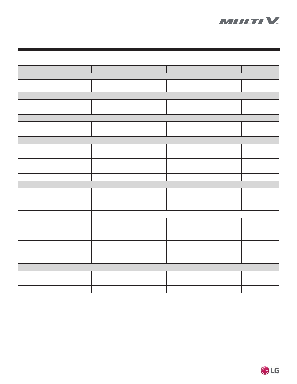
Table 2: High-Static Ducted BH Chassis IDU Specications
Model No.
ARNU073BHA4 ARNU093BHA4 ARNU123BHA4 ARNU153BHA4 ARNU183BHA4 ARNU243BHA4
Cooling Mode Performance
Capacity (Btu/h)
7,500 9,600 12,300 15,400 19,100 24,200
Power Input
1
(W)
150 150 150 150 150 150
Heating Mode Performance
Capacity (Btu/h)
8,500 10,900 13,600 17,100 21,500 27,300
Power Input
1
(W)
150 150 150 150 150 150
Entering Mixed Air
Cooling Max. (°F WB)
76 76 76 76 76 76
Heating Min. (°F DB)
59 59 59 59 59 59
Unit Data
Refrigerant Type
2
R410A R410A R410A R410A R410A R410A
Refrigerant Control
EEV EEV EEV EEV EEV EEV
Net Unit Weight (lbs.)
58.4 58.4 58.4 58.4 58.4 58.4
Shipping Weight (lbs.)
68.3 68.3 68.3 68.3 68.3 68.3
Communication Cable
4
(No. x AWG)
2 x 18 2 x 18 2 x 18 2 x 18 2 x 18 2 x 18
Fan
Type
Sirocco Sirocco Sirocco Sirocco Sirocco Sirocco
Motor
1 1 1 1 1 1
Housing
2 2 2 2 2 2
Motor/Drive
Brushless Digitally Controlled / Direct
Airflow Rate H/M/L (CFM)
Standard Mode
258 / 222 / 198 258 / 222 / 198 307 / 258 / 198 388 / 357 / 307 466 / 413 / 258 618 / 519 / 445
Airflow Rate H/M/L (CFM)
High Mode (Factory Set)
230 / 205 / 191 286 / 230 / 205 339 / 286 / 230 399 / 339 / 230 459 / 399 / 339 565 / 509 / 459
External Static Pressure (in. wg)
Standard Mode
0.23 0.23 0.23 0.23 0.23 0.23
External Static Pressure (in. wg)
High Mode (Factory Set)
0.31 0.31 0.31 0.31 0.31 0.31
Piping
Liquid Line (in., O.D.)
1/4 Flare 1/4 Flare 1/4 Flare 1/4 Flare 1/4 Flare 3/8 Flare
Vapor Line (in., O.D.)
1/2 Flare 1/2 Flare 1/2 Flare 1/2 Flare 1/2 Flare 5/8 Flare
Condensate Line (in., I.D.)
1 1 1 1 1 1
GENERAL DATA
Specications − High-Static BH Chassis

14
Multi V Ducted Indoor Units
Due to our policy of continuous product innovation, some specifications may change without notification.
©LG Electronics U.S.A., Inc., Englewood Cliffs, NJ. All rights reserved. “LG” is a registered trademark of LG Corp.
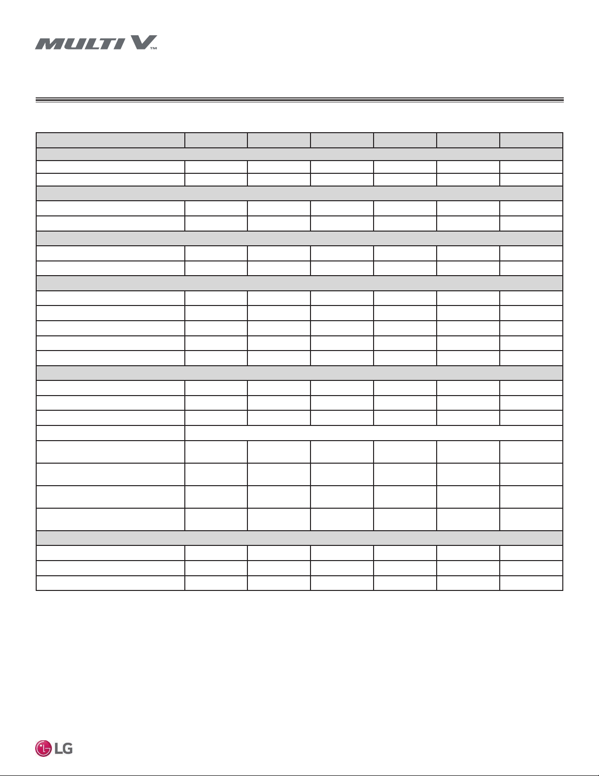
Table 3: High-Static BG Chassis IDU Specications
GENERAL DATA
1
Power Input is rated at high speed.
2
Take appropriate actions at the end of HVAC equipment life to recover, recycle, reclaim or
destroy R410A refrigerant according to applicable regulations (40 CFR Part 82, Subpart F)
under section 608 of CAA.
3
All communication cable to be minimum 18 AWG, 2-conductor, stranded, shielded and
must comply with applicable local and national codes. Ensure the communication cable
is properly grounded at the master outdoor unit only. Do not ground the ODU−IDU com-
munications cable at any other point.
EEV: Electronic Expansion Valve
Power wiring is field supplied and must comply with the applicable local and national
codes. Power Supply (V/Hz/Ø): 208-230/60/1
This unit comes with a dry nitrogen charge.
This data is rated 0 ft above sea level, with 25 ft of refrigerant line per indoor unit and a 0 ft
level difference between outdoor and indoor units. All capacities are net with a combina-
tion ratio between 95-105%.
Cooling capacity rating obtained with air entering the indoor coil at 80ºF dry bulb (DB) and
67ºF wet bulb (WB) and outdoor ambient conditions of 95ºF dry bulb (DB).
Heating capacity rating obtained with air entering the indoor unit at 70ºF dry bulb (DB) and
outdoor ambient conditions of 47ºF dry bulb (DB) and 43ºF wet bulb (WB).
Specications − High-Static BG Chassis
Model No. ARNU073BGA4 ARNU093BGA4 ARNU123BGA4 ARNU153BGA4 ARNU183BGA4
Cooling Mode Performance
Capacity (Btu/h)
7,500 9,600 12,300 15,400 19,100
Power Input
1
(W)
450 450 450 450 450
Heating Mode Performance
Capacity (Btu/h)
8,500 10,900 13,600 17,100 21,500
Power Input
1
(W)
450 450 450 450 450
Entering Mixed Air
Cooling Max. (°F WB)
76 76 76 76 76
Heating Min. (°F DB)
59 59 59 59 59
Unit Data
Refrigerant Type
2
R410A R410A R410A R410A R410A
Refrigerant Control
EEV EEV EEV EEV EEV
Net Unit Weight (lbs.)
83.8 83.8 83.8 83.8 83.8
Shipping Weight (lbs.)
94.8 94.8 94.8 94.8 94.8
Communication Cable
4
(No. x AWG)
2 x 18 2 x 18 2 x 18 2 x 18 2 x 18
Fan
Type
Sirocco Sirocco Sirocco Sirocco Sirocco
Motor
1 1 1 1 1
Housing
2 2 2 2 2
Motor/Drive
Brushless Digitally Controlled / Direct
Airflow Rate H/M/L (CFM)
Standard Mode
516 / 484 / 434 533 / 484 / 434 586 / 533 / 484 477 / 427 / 318 547 / 470 / 427
Airflow Rate H/M/L (CFM)
High Mode (Factory Set)
441 / 406 / 332 452 / 406 / 332 477 / 427 / 332 487 / 417 / 293 537 / 487 / 417
External Static Pressure (in. wg)
Standard Mode
0.15 0.15 0.15 0.23 0.23
External Static Pressure (in. wg)
High Mode (Factory Set)
0.23 0.23 0.23 0.31 0.31
Piping
Liquid Line (in., O.D.)
3/8 Flare 3/8 Flare 3/8 Flare 3/8 Flare 3/8 Flare
Vapor Line (in., O.D.)
5/8 Flare 5/8 Flare 5/8 Flare 5/8 Flare 5/8 Flare
Condensate Line (in., I.D.)
1 1 1 1 1

15
Installation Manual
Due to our policy of continuous product innovation, some specifications may change without notification.
©LG Electronics U.S.A., Inc., Englewood Cliffs, NJ. All rights reserved. “LG” is a registered trademark of LG Corp.
GENERAL DATA
Table 2: High-Static BG Chassis IDU Specications – continued
1
Power Input is rated at high speed.
2
Take appropriate actions at the end of HVAC equipment life to recover, recycle, reclaim or
destroy R410A refrigerant according to applicable regulations (40 CFR Part 82, Subpart F)
under section 608 of CAA.
3
All communication cable to be minimum 18 AWG, 2-conductor, stranded, shielded and
must comply with applicable local and national codes. Ensure the communication cable
is properly grounded at the master outdoor unit only. Do not ground the ODU−IDU com-
munications cable at any other point.
EEV: Electronic Expansion Valve
Power wiring is field supplied and must comply with the applicable local and national
codes. Power Supply (V/Hz/Ø): 208-230/60/1
This unit comes with a dry nitrogen charge.
This data is rated 0 ft above sea level, with 25 ft of refrigerant line per indoor unit and a 0 ft
level difference between outdoor and indoor units. All capacities are net with a combina-
tion ratio between 95-105%.
Cooling capacity rating obtained with air entering the indoor coil at 80ºF dry bulb (DB) and
67ºF wet bulb (WB) and outdoor ambient conditions of 95ºF dry bulb (DB).
Heating capacity rating obtained with air entering the indoor unit at 70ºF dry bulb (DB) and
outdoor ambient conditions of 47ºF dry bulb (DB) and 43ºF wet bulb (WB).
Specications − High-Static BG Chassis
Model No. ARNU243BGA4 ARNU283BGA4 ARNU363BGA4 ARNU423BGA4
Cooling Mode Performance
Capacity (Btu/h)
24,200 28,000 36,200 42,000
Power Input
1
(W)
450 450 450 450
Heating Mode Performance
Capacity (Btu/h)
27,300 31,500 40,600 43,800
Power Input
1
(W)
450 450 450 450
Entering Mixed Air
Cooling Max. (°F WB)
76 76 76 76
Heating Min. (°F DB)
59 59 59 59
Unit Data
Refrigerant Type
2
R410A R410A R410A R410A
Refrigerant Control
EEV EEV EEV EEV
Net Unit Weight (lbs.)
83.8 83.8 83.8 83.8
Shipping Weight (lbs.)
94.8 94.8 94.8 94.8
Communication Cable
4
(No. x AWG)
2 x 18 2 x 18 2 x 18 2 x 18
Fan
Type
Sirocco Sirocco Sirocco Sirocco
Motor
1 1 1 1
Housing
2 2 2 2
Motor/Drive
Brushless Digitally Controlled / Direct
Airflow Rate H/M/L (CFM)
Standard Mode
671 / 576 / 547 893 / 770 / 622 1,003 / 894 / 770 1,130 / 1,003 / 961
Airflow Rate H/M/L (CFM)
High Mode (Factory Set)
671 / 537 / 487 915 / 851 / 770 1,141 / 1,024 / 894 1,218 / 1,141 / 1,084
External Static Pressure (in. wg)
Standard Mode
0.23 0.31 0.31 0.31
External Static Pressure (in. wg)
High Mode (Factory Set)
0.31 0.39 0.39 0.39
Piping
Liquid Line (in., O.D.)
3/8 Flare 3/8 Flare 3/8 Flare 3/8 Flare
Vapor Line (in., O.D.)
5/8 Flare 5/8 Flare 5/8 Flare 5/8 Flare
Condensate Line (in., I.D.)
1 1 1 1
16
Multi V Ducted Indoor Units
Due to our policy of continuous product innovation, some specifications may change without notification.
©LG Electronics U.S.A., Inc., Englewood Cliffs, NJ. All rights reserved. “LG” is a registered trademark of LG Corp.
GENERAL DATA
1
Power Input is rated at high speed.
2
Take appropriate actions at the end of HVAC equipment life to recover, recycle, reclaim or
destroy R410A refrigerant according to applicable regulations (40 CFR Part 82, Subpart F)
under section 608 of CAA.
3
All communication cable to be minimum 18 AWG, 2-conductor, stranded, shielded and
must comply with applicable local and national codes. Ensure the communication cable
is properly grounded at the master outdoor unit only. Do not ground the ODU−IDU com-
munications cable at any other point.
EEV: Electronic Expansion Valve
Power wiring is field supplied and must comply with the applicable local and national
codes. Power Supply (V/Hz/Ø): 208-230/60/1
This unit comes with a dry nitrogen charge.
This data is rated 0 ft above sea level, with 25 ft of refrigerant line per indoor unit and a 0 ft
level difference between outdoor and indoor units. All capacities are net with a combina-
tion ratio between 95-105%.
Cooling capacity rating obtained with air entering the indoor coil at 80ºF dry bulb (DB) and
67ºF wet bulb (WB) and outdoor ambient conditions of 95ºF dry bulb (DB).
Heating capacity rating obtained with air entering the indoor unit at 70ºF dry bulb (DB) and
outdoor ambient conditions of 47ºF dry bulb (DB) and 43ºF wet bulb (WB).
Specications − High-Static BR/B8 Chassis
Table 4: High-Static BR Chassis IDU Specications
Model No. ARNU283BRA4 ARNU363BRA4 ARNU5423BRA4 ARNU483BRA4 ARNU543BRA4
Cooling Mode Performance
Capacity (Btu/h)
28,000 36,200 42,000 48,100 54,000
Power Input
1
(W)
450 450 450 450 450
Heating Mode Performance
Capacity (Btu/h)
31,500 40,600 43,800 51,200 61,400
Power Input
1
(W)
450 450 450 450 450
Entering Mixed Air
Cooling Max. (°F WB)
76 76 76 76 76
Heating Min. (°F DB)
59 59 59 59 59
Unit Data
Refrigerant Type
2
R410A R410A R410A R410A R410A
Refrigerant Control
EEV EEV EEV EEV EEV
Net Unit Weight (lbs.)
112 112 112 11 2 112
Shipping Weight (lbs.)
132 132 132 132 132
Communication Cable
4
(No. x AWG)
2 x 18 2 x 18 2 x 18 2 x 18 2 x 18
Fan
Type
Sirocco Sirocco Sirocco Sirocco Sirocco
Motor
2 2 2 2 2
Housing
2 2 2 2 2
Motor/Drive
Brushless Digitally Controlled / Direct
Airflow Rate H/M/L (CFM)
Standard Mode
1,151 / 1,105 / 1,074 1,430 / 1,151 / 1,105 1,497 / 1,430 / 1,151 1,568 /1,395 / 1,183 1,819/1,678/1,395
Airflow Rate H/M/L (CFM)
High Mode (Factory Set)
1,278 / 1,134 / 1,007 1,381 / 1,176 / 1,049 1,490 / 1,381 / 1,176 1,582/ 1,434 / 1,176 1,801/1,582/1,434
External Static Pressure (in. wg)
Standard Mode
0.39 0.39 0.39 0.39 0.39
External Static Pressure (in. wg)
High Mode (Factory Set)
0.55 0.55 0.55 0.55 0.55
Piping
Liquid Line (in., O.D.)
3/8 Flare 3/8 Flare 3/8 Flare 3/8 Flare 3/8 Flare
Vapor Line (in., O.D.)
5/8 Flare 5/8 Flare 5/8 Flare 5/8 Flare 5/8 Flare
Condensate Line (in., I.D.)
1 1 1 1 1

17
Installation Manual
Due to our policy of continuous product innovation, some specifications may change without notification.
©LG Electronics U.S.A., Inc., Englewood Cliffs, NJ. All rights reserved. “LG” is a registered trademark of LG Corp.
Table 5: High-Static B8 Chassis IDU Specications
Model No. ARNU363B8A4 ARNU423B8A4 ARNU483B8A4 ARNU763B8A4 ARNU963B8A4
Cooling Mode Performance
Capacity (Btu/h)
36,200 42,000 48,100 76,400 95,900
Power Input
1
(W)
800 800 800 800 800
Heating Mode Performance
Capacity (Btu/h)
40,600 43,800 51,200 86,000 107,500
Power Input
1
(W)
800 800 800 800 800
Entering Mixed Air
Cooling Max. (°F WB)
76 76 76 76 76
Heating Min. (°F DB)
59 59 59 59 59
Unit Data
Refrigerant Type
2
R410A R410A R410A R410A R410A
Refrigerant Control
EEV EEV EEV EEV EEV
Net Unit Weight (lbs.)
192 192 192 192 192
Shipping Weight (lbs.)
222 222 222 222 222
Communication Cable
4
(No. x AWG)
2 x 18 2 x 18 2 x 18 2 x 18 2 x 18
Fan
Type
Sirocco Sirocco Sirocco Sirocco Sirocco
Motor
2 2 2 2 2
Housing
2 2 2 2 2
Motor/Drive
Brushless Digitally Controlled / Direct
Airflow Rate H/M/L (CFM)
Standard Mode
1,896 / 1,748 / 1,550 1,963 / 1,786 / 1,589 2,048 / 1,846 / 1,670 2,050 / 1,766 / 1,766 2,684 / 2,260 / 2,260
Airflow Rate H/M/L (CFM)
High Mode (Factory Set)
1,730 / 1,317 / 1,066 1,914 / 1,458 / 1,123 2,019 / 1,518 / 1,200 2,260 / 1,766 / 1,766 2,542 / 2,260 / 2,260
External Static Pressure (in. wg)
Standard Mode
0.35 0.35 0.35 0.59 0.59
External Static Pressure (in. wg)
High Mode (Factory Set)
0.70 0.70 0.70 0.87 0.87
Piping
Liquid Line (in., O.D.)
3/8 Flare 3/8 Flare 3/8 Flare 3/8 Flare 3/8 Flare
Vapor Line (in., O.D.)
3/4 Brazed 3/4 Brazed 3/4 Brazed 3/4 Flare 7/8 Flare
Condensate Line (in., I.D.)
1 1 1 1 1
1
Power Input is rated at high speed.
2
Take appropriate actions at the end of HVAC equipment life to recover, recycle, reclaim or
destroy R410A refrigerant according to applicable regulations (40 CFR Part 82, Subpart F)
under section 608 of CAA.
3
All communication cable to be minimum 18 AWG, 2-conductor, stranded, shielded and
must comply with applicable local and national codes. Ensure the communication cable
is properly grounded at the master outdoor unit only. Do not ground the ODU−IDU com-
munications cable at any other point.
EEV: Electronic Expansion Valve
Power wiring is field supplied and must comply with the applicable local and national
codes. Power Supply (V/Hz/Ø): 208-230/60/1
This unit comes with a dry nitrogen charge.
This data is rated 0 ft above sea level, with 25 ft of refrigerant line per indoor unit and a 0 ft
level difference between outdoor and indoor units. All capacities are net with a combina-
tion ratio between 95-105%.
Cooling capacity rating obtained with air entering the indoor coil at 80ºF dry bulb (DB) and
67ºF wet bulb (WB) and outdoor ambient conditions of 95ºF dry bulb (DB).
Heating capacity rating obtained with air entering the indoor unit at 70ºF dry bulb (DB) and
outdoor ambient conditions of 47ºF dry bulb (DB) and 43ºF wet bulb (WB).

18
Multi V Ducted Indoor Units
Due to our policy of continuous product innovation, some specifications may change without notification.
©LG Electronics U.S.A., Inc., Englewood Cliffs, NJ. All rights reserved. “LG” is a registered trademark of LG Corp.
GENERAL DATA
1
Power Input is rated at high speed.
2
Take appropriate actions at the end of HVAC equipment life to recover, recycle, reclaim or
destroy R410A refrigerant according to applicable regulations (40 CFR Part 82, Subpart F)
under section 608 of CAA.
3
All communication cable to be minimum 18 AWG, 2-conductor, stranded, shielded and
must comply with applicable local and national codes. Ensure the communication cable
is properly grounded at the master outdoor unit only. Do not ground the ODU−IDU com-
munications cable at any other point.
EEV: Electronic Expansion Valve
Power wiring is field supplied and must comply with the applicable local and national
codes. Power Supply (V/Hz/Ø): 208-230/60/1
This unit comes with a dry nitrogen charge.
This data is rated 0 ft above sea level, with 25 ft of refrigerant line per indoor unit and a 0 ft
level difference between outdoor and indoor units. All capacities are net with a combina-
tion ratio between 95-105%.
Cooling capacity rating obtained with air entering the indoor coil at 80ºF dry bulb (DB) and
67ºF wet bulb (WB) and outdoor ambient conditions of 95ºF dry bulb (DB).
Heating capacity rating obtained with air entering the indoor unit at 70ºF dry bulb (DB) and
outdoor ambient conditions of 47ºF dry bulb (DB) and 43ºF wet bulb (WB).
Specications − Low-Static B3/B4 Chassis
Table 6: Low-Static Built-In B3/B4 Chassis IDU Specications
Model No. ARNU073B3G4 ARNU093B3G4 ARNU123B3G4 ARNU153B3G4 ARNU183B4G4 ARNU243B4G4
Cooling Mode Performance
Capacity (Btu/h)
7,500 9,600 12,300 15,400 19,100 24,200
Power Input
1
(W)
85 85 85 85 85 115
Heating Mode Performance
Capacity (Btu/h)
8,500 10,900 13,600 17,100 21,500 27,300
Power Input
1
(W)
85 85 85 85 85 115
Entering Mixed Air
Cooling Max. (°F WB)
76 76 76 76 76 76
Heating Min. (°F DB)
59 59 59 59 59 59
Unit Data
Refrigerant Type
2
R410A R410A R410A R410A R410A R410A
Refrigerant Control
EEV EEV EEV EEV EEV EEV
Net Unit Weight (lbs.)
46.3 46.3 46.3 46.3 57.3 57.3
Shipping Weight (lbs.)
53.3 53.3 53.3 53.3 67.2 67.2
Communication Cable
4
(No. x AWG)
2 x 18 2 x 18 2 x 18 2 x 18 2 x 18 2 x 18
Fan
Type
Sirocco Sirocco Sirocco Sirocco Sirocco Sirocco
Motor
2 2 2 2 2 2
Housing
3 3 3 3 4 4
Motor/Drive
Brushless Digitally Controlled / Direct
Airflow Rate H/M/L (CFM)
Standard Mode
283 / 229 / 194 318 / 247 / 212 353 / 283 / 229 388 / 353 / 283 494 / 424 / 353 600 / 530 / 353
Airflow Rate H/M/L (CFM)
High Mode (Factory Set)
283 / 229 / 194 318 / 247 / 212 353 / 283 / 229 388 / 353 / 283 494 / 424 / 353 600 / 530 / 353
External Static Pressure (in. wg)
Standard Mode
0 0 0 0 0 0
External Static Pressure (in. wg)
High Mode (Factory Set)
0.08 0.08 0.08 0.08 0.08 0.08
Piping
Liquid Line (in., O.D.)
1/4 Flare 1/4 Flare 1/4 Flare 1/4 Flare 1/4 Flare 3/8 Flare
Vapor Line (in., O.D.)
1/2 Flare 1/2 Flare 1/2 Flare 1/2 Flare 1/2 Flare 5/8 Flare
Condensate Line (in., I.D.)
1 1 1 1 1 1
19
Installation Manual
Due to our policy of continuous product innovation, some specifications may change without notification.
©LG Electronics U.S.A., Inc., Englewood Cliffs, NJ. All rights reserved. “LG” is a registered trademark of LG Corp.
1
Power Input is rated at high speed.
2
Take appropriate actions at the end of HVAC equipment life to recover, recycle, reclaim or
destroy R410A refrigerant according to applicable regulations (40 CFR Part 82, Subpart F)
under section 608 of CAA.
3
All communication cable to be minimum 18 AWG, 2-conductor, stranded, shielded and
must comply with applicable local and national codes. Ensure the communication cable
is properly grounded at the master outdoor unit only. Do not ground the ODU−IDU com-
munications cable at any other point.
EEV: Electronic Expansion Valve
Power wiring is field supplied and must comply with the applicable local and national
codes. Power Supply (V/Hz/Ø): 208-230/60/1
This unit comes with a dry nitrogen charge.
This data is rated 0 ft above sea level, with 25 ft of refrigerant line per indoor unit and a 0 ft
level difference between outdoor and indoor units. All capacities are net with a combina-
tion ratio between 95-105%.
Cooling capacity rating obtained with air entering the indoor coil at 80ºF dry bulb (DB) and
67ºF wet bulb (WB) and outdoor ambient conditions of 95ºF dry bulb (DB).
Heating capacity rating obtained with air entering the indoor unit at 70ºF dry bulb (DB) and
outdoor ambient conditions of 47ºF dry bulb (DB) and 43ºF wet bulb (WB).
Table 7: Low-Static Ducted L1/L2/L3 Chassis IDU Specications
GENERAL DATA
Specications − Low-Static Ducted L1/L2/L3 Chassis
Model No. ARNU073L1G4 ARNU093L1G4 ARNU123L2G4 ARNU153L2G4 ARNU183L2G4 ARNU243L3G4
Cooling Mode Performance
Capacity (Btu/h)
7,500 9,600 12,300 15,400 19,100 24,000
Power Input
1
(W)
40 40 85 85 85 115
Heating Mode Performance
Capacity (Btu/h)
8,500 10,900 13,600 17,100 21,500 27,300
Power Input
1
(W)
40 40 85 85 85 115
Entering Mixed Air
Cooling Max. (°F WB)
76 76 76 76 76 76
Heating Min. (°F DB)
59 59 59 59 59 59
Unit Data
Refrigerant Type
2
R410A R410A R410A R410A R410A R410A
Refrigerant Control
EEV EEV EEV EEV EEV EEV
Net Unit Weight (lbs.)
38.6 38.6 50.7 50.7 50.7 59.5
Shipping Weight (lbs.)
47.4 47.4 60.6 60.6 60.6 68.3
Communication Cable
4
(No. x AWG)
2 x 18 2 x 18 2 x 18 2 x 18 2 x 18 2 x 18
Fan
Type
Sirocco Sirocco Sirocco Sirocco Sirocco Sirocco
Motor
1 1 2 2 2 2
Housing
2 2 3 3 3 4
Motor/Drive
Brushless Digitally Controlled / Direct
Airflow Rate H/M/L (CFM)
Standard Mode
270 / 230 / 200 320 / 250 / 200 360 / 310 / 250 450 / 360 / 310 530 / 450 / 360 710 / 570 / 430
Airflow Rate H/M/L (CFM)
High Mode (Factory Set)
270 / 230 / 200 320 / 250 / 200 360 / 310 / 250 450 / 360 / 310 530 / 450 / 360 710 / 570 / 430
External Static Pressure (in. wg)
Standard Mode
0 0 0 0 0 0
External Static Pressure (in. wg)
High Mode (Factory Set)
0.1 0.1 0.1 0.1 0.1 0.1
Piping
Liquid Line (in., O.D.)
1/4 Flare 1/4 Flare 1/4 Flare 1/4 Flare 1/4 Flare 3/8 Flare
Vapor Line (in., O.D.)
1/2 Flare 1/2 Flare 1/2 Flare 1/2 Flare 1/2 Flare 5/8 Flare
Condensate Line (in., I.D.)
1 1 1 1 1 1

20
Multi V Ducted Indoor Units
Due to our policy of continuous product innovation, some specifications may change without notification.
©LG Electronics U.S.A., Inc., Englewood Cliffs, NJ. All rights reserved. “LG” is a registered trademark of LG Corp.
1
Power Input is rated at high speed.
2
Take appropriate actions at the end of HVAC equipment life to recover, recycle, reclaim or
destroy R410A refrigerant according to applicable regulations (40 CFR Part 82, Subpart F)
under section 608 of CAA.
3
All communication cable to be minimum 18 AWG, 2-conductor, stranded, shielded and
must comply with applicable local and national codes. Ensure the communication cable
is properly grounded at the master outdoor unit only. Do not ground the ODU−IDU com-
munications cable at any other point.
EEV: Electronic Expansion Valve
Power wiring is field supplied and must comply with the applicable local and national
codes. Power Supply (V/Hz/Ø): 208-230/60/1
This unit comes with a dry nitrogen charge.
This data is rated 0 ft above sea level, with 25 ft of refrigerant line per indoor unit and a 0 ft
level difference between outdoor and indoor units. All capacities are net with a combina-
tion ratio between 95-105%.
Cooling capacity rating obtained with air entering the indoor coil at 80ºF dry bulb (DB) and
67ºF wet bulb (WB) and outdoor ambient conditions of 95ºF dry bulb (DB).
Heating capacity rating obtained with air entering the indoor unit at 70ºF dry bulb (DB) and
outdoor ambient conditions of 47ºF dry bulb (DB) and 43ºF wet bulb (WB).
Table 8: Vertical Air Handler NJ Chassis IDU Specications
Model No. ARNU123NJA4 ARNU183NJA4 ARNU243NJA4 ARNU303NJA4 ARNU363NJA4
Cooling Mode Performance
Capacity (Btu/h)
12,000 18,000 24,000 30,000 36,000
Power Input
1
(W)
80 80 120 178 228
Heating Mode Performance
Capacity (Btu/h)
13,500 20,000 27,000 34,000 40,000
Power Input
1
(W)
80 80 120 178 228
Entering Mixed Air
Cooling Max. (°F WB)
76 76 76 76 76
Heating Min. (°F DB)
59 59 59 59 59
Unit Data
Refrigerant Type
2
R410A R410A R410A R410A R410A
Refrigerant Control
EEV EEV EEV EEV EEV
Net Unit Weight (lbs.)
117 117 117 117 121
Shipping Weight (lbs.)
140 140 140 140 144
Communication Cable
4
(No. x AWG)
2 x 18 2 x 18 2 x 18 2 x 18 2 x 18
Fan
Type
Sirocco Sirocco Sirocco Sirocco Sirocco
Motor
1 1 1 1 1
Housing
1 1 1 1 1
Motor/Drive
Brushless Digitally Controlled / Direct
Airflow Rate H/M/L (CFM)
Standard Mode
530 / 480 / 380 580 / 530 / 480 710 / 640 / 480 880 / 800 / 630 990 / 880 / 800
Airflow Rate H/M/L (CFM)
High Mode (Factory Set)
530 / 480 / 380 580 / 530 / 480 710 / 640 / 480 880 / 800 / 630 990 / 880 / 800
External Static Pressure (in. wg)
Standard Mode
0.3 0.3 0.3 0.3 0.3
External Static Pressure (in. wg)
High Mode (Factory Set)
0.5 0.5 0.5 0.5 0.5
Piping
Liquid Line (in., O.D.)
1/4 Flare 1/4 Flare 3/8 Flare 3/8 Flare 3/8 Flare
Vapor Line (in., O.D.)
1/2 Flare 1/2 Flare 5/8 Flare 5/8 Flare 5/8 Flare
Condensate Line (in., I.D.)
1 1 1 1 1
GENERAL DATA
Specications − Vertical Air Handler NJ Chassis

21
Installation Manual
Due to our policy of continuous product innovation, some specifications may change without notification.
©LG Electronics U.S.A., Inc., Englewood Cliffs, NJ. All rights reserved. “LG” is a registered trademark of LG Corp.
GENERAL DATA
Specications − Vertical Air Handler NK Chassis
1
Power Input is rated at high speed.
2
Take appropriate actions at the end of HVAC equipment life to recover, recycle, reclaim or
destroy R410A refrigerant according to applicable regulations (40 CFR Part 82, Subpart F)
under section 608 of CAA.
3
All communication cable to be minimum 18 AWG, 2-conductor, stranded, shielded and
must comply with applicable local and national codes. Ensure the communication cable
is properly grounded at the master outdoor unit only. Do not ground the ODU−IDU com-
munications cable at any other point.
EEV: Electronic Expansion Valve
Power wiring is field supplied and must comply with the applicable local and national
codes. Power Supply (V/Hz/Ø): 208-230/60/1
This unit comes with a dry nitrogen charge.
This data is rated 0 ft above sea level, with 25 ft of refrigerant line per indoor unit and a 0 ft
level difference between outdoor and indoor units. All capacities are net with a combina-
tion ratio between 95-105%.
Cooling capacity rating obtained with air entering the indoor coil at 80ºF dry bulb (DB) and
67ºF wet bulb (WB) and outdoor ambient conditions of 95ºF dry bulb (DB).
Heating capacity rating obtained with air entering the indoor unit at 70ºF dry bulb (DB) and
outdoor ambient conditions of 47ºF dry bulb (DB) and 43ºF wet bulb (WB).
Table 9: Vertical Air Handler NK Chassis IDU Specications
Model No. ARNU423NKA4 ARNU483NKA4 ARNU543NKA4
Cooling Mode Performance
Capacity (Btu/h)
42,000 48,000 54,000
Power Input
1
(W)
260 330 366
Heating Mode Performance
Capacity (Btu/h)
46,000 54,000 60,000
Power Input
1
(W)
260 330 366
Entering Mixed Air
Cooling Max. (°F WB)
76 76 76
Heating Min. (°F DB)
59 59 59
Unit Data
Refrigerant Type
2
R410A R410A R410A
Refrigerant Control
EEV EEV EEV
Net Unit Weight (lbs.)
165 165 165
Shipping Weight (lbs.)
181 181 181
Communication Cable
4
(No. x AWG)
2 x 18 2 x 18 2 x 18
Fan
Type
Sirocco Sirocco Sirocco
Motor
1 1 1
Housing
1 1 1
Motor/Drive
Brushless Digitally Controlled / Direct
Airflow Rate H/M/L (CFM)
Standard Mode
1,250 / 1,100 / 1,000 1,400 / 1,260 / 1,000 1,475 / 1,400 / 1,260
Airflow Rate H/M/L (CFM)
High Mode (Factory Set)
1,250 / 1,100 / 1,000 1,400 / 1,260 / 1,000 1,475 / 1,400 / 1,260
External Static Pressure (in. wg)
Standard Mode
0.3 0.3 0.3
External Static Pressure (in. wg)
High Mode (Factory Set)
0.5 0.5 0.5
Piping
Liquid Line (in., O.D.)
3/8 Flare 3/8 Flare 3/8 Flare
Vapor Line (in., O.D.)
5/8 Flare 5/8 Flare 5/8 Flare
Condensate Line (in., I.D.)
1 1 1
22
Multi V Ducted Indoor Units
Due to our policy of continuous product innovation, some specifications may change without notification.
©LG Electronics U.S.A., Inc., Englewood Cliffs, NJ. All rights reserved. “LG” is a registered trademark of LG Corp.
GENERAL DATA
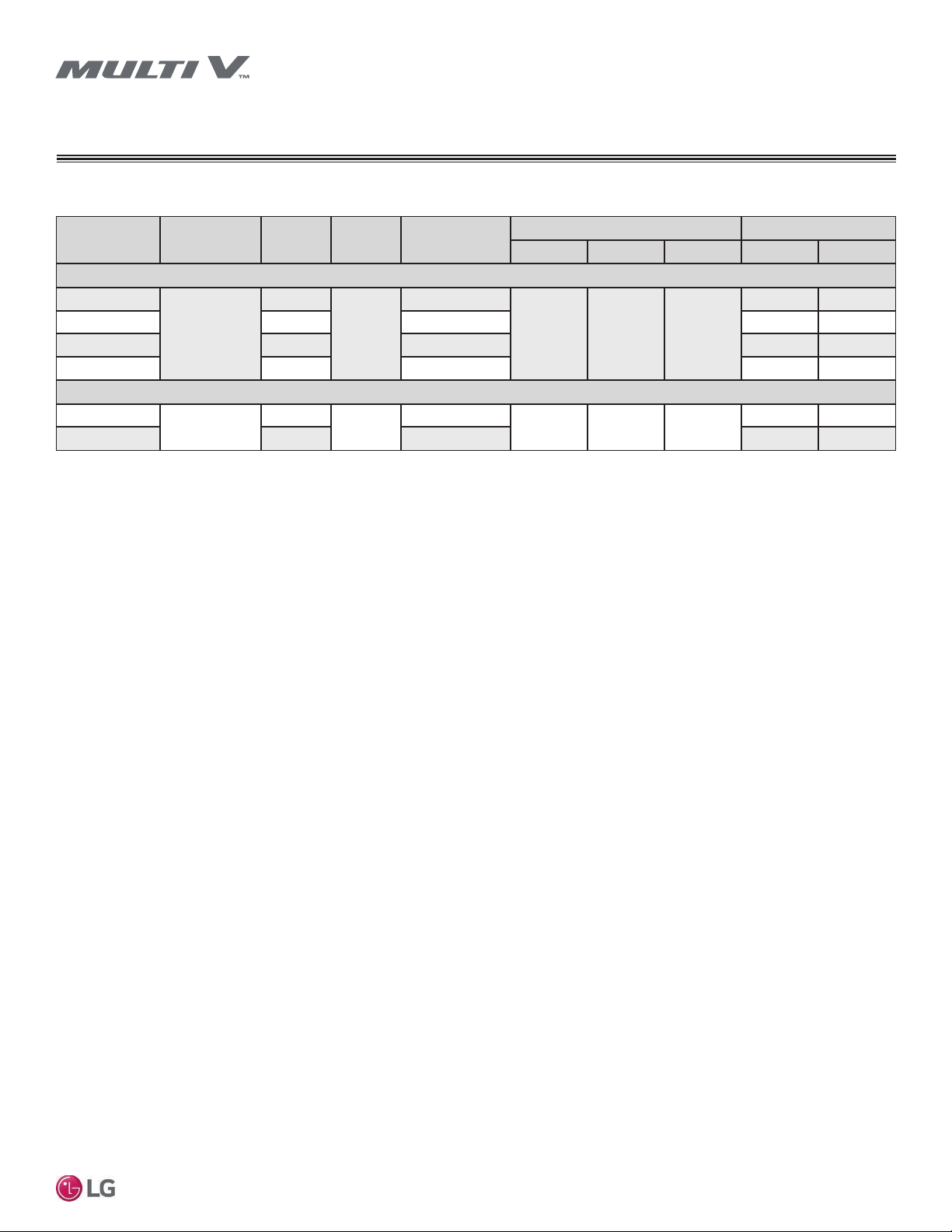
Electrical − High-Static BH/BG/BR/B8 Chassis
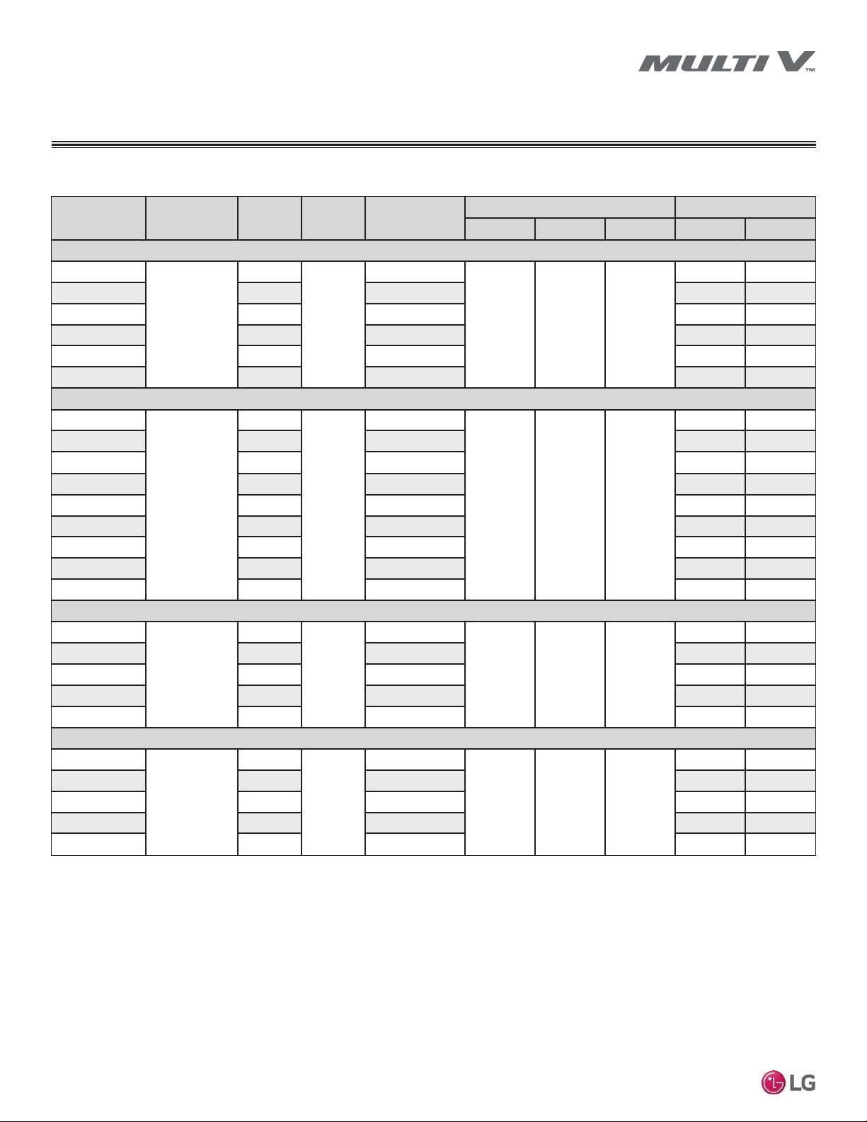
Table 10: High-Static BH/BG/BR/B8 Chassis Indoor Unit Electrical Data.
Model Voltage Range MCA MOP Rated Amps (A)
Power Supply Power Input (W)
Hz Volts Phase Cooling Heating
BH Units
ARNU073BHA4
187-253
1.32
15
1.06
60 208-230 1
150 150
ARNU093BHA4 1.32 1.06 150 150
ARNU123BHA4 1.32 1.06 150 150
ARNU153BHA4 1.32 1.06 150 150
ARNU183BHA4 1.32 1.06 150 150
ARNU243BHA4 1.32 1.06 150 150
BG Units
ARNU073BGA4
187-253
3.3
15
2.65
60 208-230 1
450 450
ARNU093BGA4 3.3 2.65 450 450
ARNU123BGA4
3.3 2.65 450 450
ARNU153BGA4 3.3 2.65 450 450
ARNU183BGA4 3.3 2.65 450 450
ARNU243BGA4 3.3 2.65 450 450
ARNU283BGA4 3.3 2.65 450 450
ARNU363BGA4 3.3 2.65 450 450
ARNU423BGA4 3.3 2.65 450 450
BR Units
ARNU283BRA4
187-253
4.4
15
3.5
60 208-230 1
450 450
ARNU363BRA4 4.4 3.5 450 450
ARNU423BRA4 4.4 3.5 450 450
ARNU483BRA4 4.4 3.5 450 450
ARNU543BRA4 4.4 3.5 450 450
B8 Units
ARNU363B8A4
187-253
6.5
15
5.2
60 208-230 1
800 800
ARNU423B8A4 6.5 5.2 800 800
ARNU483B8A4 6.5 5.2 800 800
ARNU763B8A4 6.5 5.2 800 800
ARNU963B8A4
6.5 5.2 800 800
MCA : Minimum Circuit Ampacity.
MOP : Maximum Overcurrent Protection.
Units are suitable for use on an electrical system where voltage supplied to unit terminals is within the listed range limits.
Select wire size based on the larger MCA value.
Instead of fuse, use circuit breaker.
23
Installation Manual
Due to our policy of continuous product innovation, some specifications may change without notification.
©LG Electronics U.S.A., Inc., Englewood Cliffs, NJ. All rights reserved. “LG” is a registered trademark of LG Corp.
GENERAL DATA
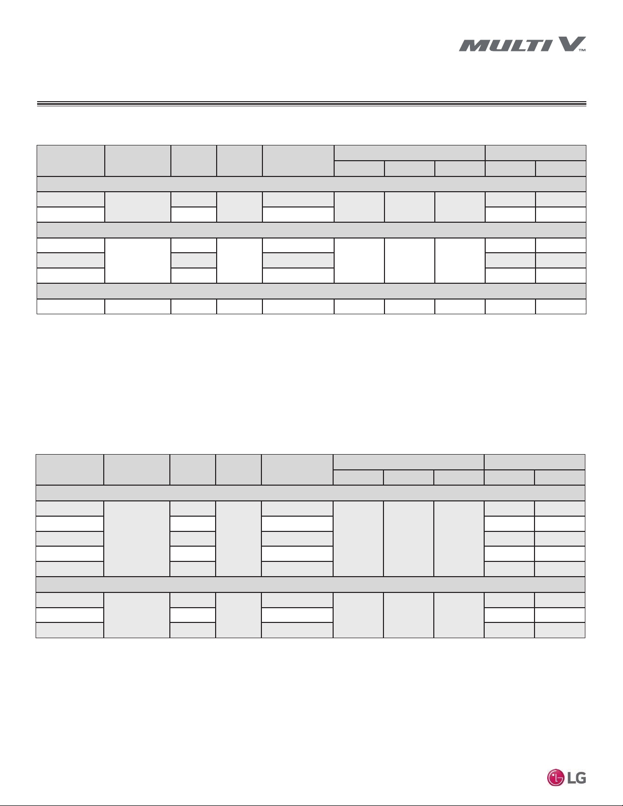
Electrical − Low-Static Built-In B3/B4 Chassis
Table 11: Low-Static Built-In B3/B4 Chassis Electrical Data.
Model Voltage Range MCA MOP Rated Amps (A)
Power Supply Power Input (W)
Hz Volts Phase Cooling Heating
B3 Units
ARNU073B3G4
187-253
1.0
15
0.76
60 208-230 1
85 85
ARNU093B3G4 1.0 0.76 85 85
ARNU123B3G4 1.0 0.76 85 85
ARNU153B3G4 1.0 0.76 85 85
B4 Units
ARNU183B4G4
187-253
1.2
15
0.97
60 208-230 1
115 115
ARNU243B4G4 1.2 0.97 115 115
MCA : Minimum Circuit Ampacity.
MOP : Maximum Overcurrent Protection.
Units are suitable for use on an electrical system where voltage supplied to unit terminals is within the listed range limits.
Select wire size based on the larger MCA value.
Instead of fuse, use circuit breaker.
24
Multi V Ducted Indoor Units
Due to our policy of continuous product innovation, some specifications may change without notification.
©LG Electronics U.S.A., Inc., Englewood Cliffs, NJ. All rights reserved. “LG” is a registered trademark of LG Corp.
GENERAL DATA
Electrical − Low-Static Ducted L1/L2/L3 Chassis
Table 12: Low-Static Ducted L1/L2/L3 Chassis Electrical Data.
Model Voltage Range MCA MOP Rated Amps (A)
Power Supply Power Input (W)
Hz Volts Phase Cooling Heating
L1 Units
ARNU073L1G4
208-230
0.5
15
0.4
60 208-230 1
40 40
ARNU093L1G4 0.5 0.4 40 40
L2 Units
ARNU123L2G4
208-230
1.0
15
0.76
60 208-230 1
85 85
ARNU153L2G4 1.0 0.76 85 85
ARNU183L2G4 1.0 0.76 85 85
L3 Units
ARNU243L3G4 208-230 1.2 15 0.97 60 208-230 1 115 115
MCA : Minimum Circuit Ampacity.
MOP : Maximum Overcurrent Protection.
Units are suitable for use on an electrical system where voltage supplied to unit terminals is within the listed range limits.
Select wire size based on the larger MCA value.
Instead of fuse, use circuit breaker.
Table 13: Vertical Air Handler NJ/NK Chassis Electrical Data.
Model Voltage Range MCA MOP Rated Amps (A)
Power Supply Power Input (W)
Hz Volts Phase Cooling Heating
NJ Units
ARNU123NJA4
208-230
1.4
15
1.12
60 208-230 1
228 228
ARNU183NJA4 1.4 1.12 228 228
ARNU243NJA4 1.4 1.12 228 228
ARNU303NJA4 1.4 1.12 228 228
ARNU363NJA4 1.4 1.12 228 228
NK Units
ARNU423NKA4
208-230
2.3
15
1.8
60 208-230 1
366 366
ARNU483NKA4 2.3 1.8 366 366
ARNU543NKA4 2.3 1.8 366 366
MCA : Minimum Circuit Ampacity.
MOP : Maximum Overcurrent Protection.
Units are suitable for use on an electrical system where voltage supplied to unit terminals is within the listed range limits.
Select wire size based on the larger MCA value.
Instead of fuse, use circuit breaker.
Loading...