


ROOM AIR CONDITIONER
SERVICE MANUAL
CAUTION
-BEFORE SERVICING THE UNIT,
READ THE SAFETY PRECAUTIONS IN THIS MANUAL.
-ONLY FOR AUTHORIZED SERVICE
MODEL: BG-81A/LT0810CR/LT080CSG BG-101A/LT1010CR/LT1030CR LT1210CR/LT121CSG/BG-123A LT1230CR/LT1430CR
CONTENTS
1. PREFACE |
|
2.4 REFRIGERATION CYCLE................................. |
10 |
|
1.1 SAFETY PRECAUTIONS ............................... |
2 |
2.4.1 CONDENSER ...................................... |
10 |
|
1.2 INSULATION RESISTANCE TEST................. |
2 |
2.4.2 EVAPORATOR .................................... |
10 |
|
1.3 SPECIFICATIONS .......................................... |
3 |
2.4.3 CAPILLARY TUBE............................... |
10 |
|
1.4 FEATURES ..................................................... |
5 |
3. INSTALLATION |
|
|
1.5 CONTROL LOCATIONS ................................. |
5 |
3.1 INSTALLATION REQUIREMENTS............... |
13 |
|
2. DISASSEMBLY INSTRUCTIONS |
|
3.2 INSTALLATION............................................. |
14 |
|
2.1 MECHANICAL PARTS.................................... |
6 |
3.3 PROCEDURE A............................................ |
15 |
|
2.1.1 FRONT GRILLE ..................................... |
6 |
3.4 PROCEDURE B............................................ |
16 |
|
2.1.2 CABINET................................................ |
6 |
3.5 PROCEDURE C............................................ |
18 |
|
2.1.3 CONTROL BOX ..................................... |
6 |
4. TROUBLESHOOTING GUIDE |
|
|
2.2 AIR HANDLING PARTS.................................. |
7 |
4.1 OUTSIDE DIMENSIONS............................... |
20 |
|
2.2.1 ORIFICE, HEATER ASSY AND TURBO FAN ......... |
7 |
4.2 PIPING SYSTEM .......................................... |
20 |
|
2.2.2 FAN ........................................................ |
7 |
4.3 TROUBLESHOOTING GUIDE...................... |
21 |
|
2.2.3 SHROUD................................................ |
8 |
5. SCHEMATIC DIAGRAM |
|
|
2.3 ELECTRICAL PARTS |
8 |
|
||
5.1 CIRCUIT DIAGRAM |
27 |
|||
2.3.1 MOTOR |
8 |
|||
6. EXPLODED VIEW |
|
|||
2.3.2 COMPRESSOR ..................................... |
8 |
27 |
||
2.3.3 CAPACITOR .......................................... |
8 |
7. REPLACEMENT PARTS LIST |
28 |
|
2.3.4 POWER CORD |
9 |
|||
|
|
|||
2.3.5 THERMISTOR ....................................... |
9 |
|
|
1. PREFACE
This SERVICE MANUAL provides various service information, including the mechanical and electrical parts etc. This room air conditioner was manufactured and assembled under a strict quality control system. The refrigerant is charged at the factory. Be sure to read the safety precautions prior to servicing the unit.
1.1 SAFETY PRECAUTIONS |
1.2 INSULATION RESISTANCE TEST |
1.When servicing the unit, turn off the air conditioner and unplug the power cord.
2.Observe the original lead dress.
If a short circuit is found, replace all parts which have been overheated or damaged by the short circuit.
3.After servicing the unit, make an insulation resistance test to protect the customer from being exposed to shock hazards.
1.Unplug the power cord and connect a jumper between 2 pins (black and white).
2.The grounding conductor (green or green & yellow) is to be open.
3.Measure the resistance value with an ohm meter between the jumpered lead and each exposed metallic part on the equipment.
4.The value should be over 1MΩ.
—2—

1.3 SPECIFICATIONS
1.3.1 FOR BG-101A/LT1010CR/LT121CSG/LT1210CR/LT0810CR/LT080CSG/BG-81A
|
|
MODELS |
BG-101A/LT1010CR |
LT121CSG/LT1210CR |
LT0810CR/LT080CSG |
REMARK |
|||
ITEMS |
|
|
|
||||||
|
|
|
|
|
|
|
/BG-81A |
|
|
|
|
|
|
|
|
|
|
|
|
POWER SUPPLY |
|
|
|
|
1Ø, 115V, 60Hz |
|
|
|
|
|
|
|
|
|
|
|
|
|
|
COOLING CAPACITY |
(Btu/h) |
9,800 |
11,500 |
|
8,000 |
|
|||
|
|
|
|
|
|
|
|
|
|
INPUT |
|
(W) |
1,110 |
1,310 |
|
830 |
|
||
|
|
|
|
|
|
|
|
|
|
RUNNING CURRENT |
(A) |
10.2 |
12.0 |
|
7.5 |
|
|||
|
|
|
|
|
|
|
|
|
|
E.E.R |
|
(Btu/w.h) |
8.8 |
8.8 |
|
9.6 |
|
||
|
|
|
|
|
|
|
|
||
REFRIGERANT (R-22) CHARGE(g) |
470g(16.6OZ) |
500g(17.6OZ) |
|
|
545g(19.2OZ) |
|
|||
|
|
|
|
|
|
|
|
|
|
OPERATING |
INDOOR (°C) |
|
26.7(DB) 19.4(WB) |
|
|
|
|
||
|
|
|
|
|
|
|
|
|
|
TEMPERATURE |
OUTDOOR (°C) |
|
35(DB) 23.9(WB) |
|
|
|
|
||
|
|
|
|
|
|
|
|
|
|
EVAPORATOR |
|
|
|
3 ROW 12STACKS |
|
|
2ROW12STACKS |
|
|
|
|
|
|
|
|
|
|
|
|
CONDENSER |
|
|
|
2ROW 17STACKS, L-BENDING TYPE |
LOUVERED-FIN TYPE |
||||
|
|
|
|
|
|
|
|
|
|
FAN, INDOOR |
|
|
|
|
TURBO FAN |
|
|
|
|
|
|
|
|
|
|
|
|
|
|
FAN, OUTDOOR |
|
|
|
PROPELLER TYPE FAN WITH SLINGER-RING |
|
||||
|
|
|
|
|
|
|
|
||
FAN SPEEDS, FAN/COOLING |
|
3/3 |
|
|
|
|
|||
|
|
|
|
|
|
|
|
|
|
FAN MOTOR |
|
|
|
|
4POLES |
|
|
|
|
|
|
|
|
|
|
|
|
||
OPERATION CONTROL |
|
ELECTRIC |
|
|
|
|
|||
|
|
|
|
|
|
|
|
||
ROOM TEMP. CONTROL |
|
THERMISTOR |
|
|
|
|
|||
|
|
|
|
|
|
|
|||
AIR DIRECTION CONTROL |
VERTICAL LOUVER(RIGHT & LEFT) |
|
|||||||
|
|
|
|
|
|
|
|
|
|
|
|
|
|
HORIZONTAL LOUVER(UP & DOWN) |
|
||||
|
|
|
|
|
|
|
|
|
|
CONSTRUCTION |
|
|
|
|
TOP-DOWN |
|
|
|
|
|
|
|
|
|
|
|
|
||
PROTECTOR |
COMPRESSOR |
EXTERNAL OVERLOAD PROTECTOR |
|
||||||
|
|
|
|
|
|
|
|
||
|
FAN MOTOR |
INTERNAL THERMAL PROTECTOR |
|
||||||
|
|
|
|
|
|
|
|
|
|
POWER CORD |
|
|
|
2.3m (3WIRES WITH GROUNDING) |
|
||||
|
|
|
|
|
|
|
|
|
|
|
|
|
|
ATTACHMENT PLUG(CORD-CONNECTED TYPE, LCDI) |
|
||||
|
|
|
|
|
|
|
|
|
|
DRAIN SYSTEM |
|
|
|
SPLASHED BY FAN SLINGER |
|
||||
|
|
|
|
|
|
|
|
|
|
NET WEIGHT |
(lbs/kg) |
78/35 |
80/36 |
|
73/33 |
|
|||
|
|
|
|
|
|
|
|
|
|
DIMENSION |
|
|
(inch) |
|
24 x 1413/32 x 20 3/32 |
|
|||
|
|
|
|
|
|
|
|
|
|
(W x H x D) |
|
|
(mm) |
|
610 x 366 x 499 |
|
|
|
|
|
|
|
|
|
|
|
|
|
|
SLEEVE DIMESION |
|
(inch) |
|
25 7/8 x 15 17/32 x 16 |
23/32 |
OPTIONAL |
|||
|
|
|
|
|
|
|
|
|
|
(W x H x D) |
|
|
(mm) |
|
656 x 394 x 425 |
|
|
|
PART |
|
|
|
|
|
|
|
|||
|
|
|
|
|
|
|
|
|
|
SLEEVE DEPTH |
|
|
(inch) |
|
20 1/2 |
|
|
|
|
WITH FRONT GRILLE |
|
(mm) |
|
521 |
|
|
|
|
|
|
|
|
|
|
|
|
|
|
|
—3—

1.3.2 FOR LT1030CR/LT1230CR/BG-123A/LT1430CR |
|
|
||||
|
MODELS |
LT1030CR |
LT1230CR/BG-123A |
LT1430CR |
REMAR |
|
ITEMS |
|
|
||||
|
|
|
|
|
|
|
POWER SUPPLY |
|
|
|
1Ø, 230/208V, 60Hz |
|
|
COOLING CAPACITY |
(Btu/h) |
10,000/9,800 |
11,500/11,200 |
13,200/12,800 |
|
|
INPUT |
|
(W) |
1,060/1,040 |
1,310/1,270 |
1,550/1,500 |
|
RUNNING CURRENT |
|
(A) |
4.7/5.2 |
6.0/6.4 |
7.1/7.6 |
|
E.E.R. |
|
(Btu/W.h) |
9.4/9.4 |
8.8/8.8 |
8.5/8.5 |
|
OPERATING |
INDOOR (°C) |
480g(16.9OZ) |
485g(17.1OZ) |
545g(19.2OZ) |
|
|
TEMPERA-TURE |
OUTDOOR (°C) |
|
26.7(DB) 19.4(WB) |
|
|
|
REFRIGERANT (R-22) CHARGE(g) |
|
35(DB) 23.9(WB) |
|
|
||
EVAPORATOR |
|
|
3 ROW 12STACKS |
3 ROW 12STACKS 3 ROW 12STACKS |
|
|
CONDENSER |
|
|
2ROW 17STACKS, L-BENDING TYPE |
LOUVERED-FINTYPE |
||
FAN, INDOOR |
|
|
|
TURBO FAN |
|
|
FAN, OUTDOOR |
|
|
PROPELLER TYPE FAN WITH SLINGER-RING |
|
||
FAN SPEEDS (FAN/COOLING/HEATING) |
|
3/3 |
|
|
||
FAN MOTOR |
|
|
6 POLES |
4POLES |
4POLES |
|
OPERATION CONTROL |
|
|
ELECTRIC |
|
|
|
ROOM TEMP. CONTROL |
|
|
THERMISTOR |
|
|
|
AIR DIRECTION CONTROL |
|
VERTICAL LOUVER(RIGHT & LEFT) |
|
|||
|
HORIZONTAL LOUVER(UP & DOWN) |
|
||||
|
|
|
|
|||
CONSTRUCTION |
|
|
TOP-DOWN |
|
|
|
COMPRESSOR |
EXTERNAL OVERLOAD PROTECTOR |
|
||||
PROTECTOR |
|
|
INTERNAL THERMAL PROTECTOR |
|
||
FAN MOTOR |
|
|||||
POWER CORD |
|
|
1.4m (3WIRES WITH GROUNDING) |
|
||
|
|
ATTACHMENT PLUG(CORD-CONNECTED TYPE, LCDI) |
|
|||
|
|
|
|
|||
DRAIN SYSTEM |
|
|
SPLASHED BY FAN SLINGER |
|
||
NET WEIGHT |
|
(lbs/kg) |
78/35 |
80/36 |
87/40 |
|
DIMENSION |
|
(inch) |
|
24 x 14 13/32 x 20 3/32 |
|
|
(W x H x D) |
|
(mm) |
|
610 x 366 x 499 |
|
|
SLEEVE DIMESION |
(inch) |
25 7/8 x 15 17/32 x 16 23/32 |
OPTIONAL |
|||
(W x H x D) |
|
(mm) |
|
656 x 394 x 425 |
PART |
|
SLEEVE DEPTH |
|
(inch) |
|
20 1/2 |
|
|
WITH FRONT GRILLE |
(mm) |
|
521 |
|
|
|
|
|
|
—4— |
|
|
|
1.4 FEATURES
•Designed for cooling only.
•Powerful and quiet cooling.
•Top-down chassis for the simple installation and service.
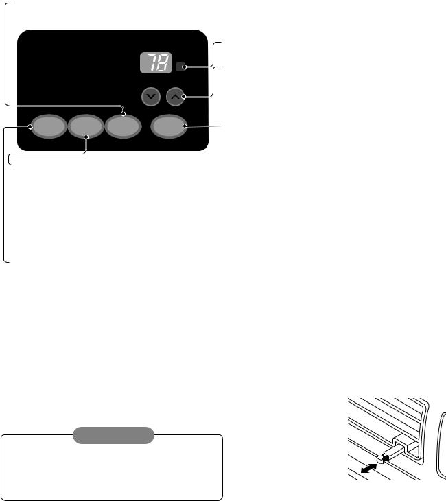
1.5 CONTROL LOCATIONS
1.5.1 COOLING ONLY MODEL
• OPERATION
FAN SPEED
•Side air-intake, side cooled-air discharge.
•Built in adjustable THERMISTOR and THERMOSTAT.
•Washable one-touch filter.
•Compact size.
• Every time you push this button, it advances the setting as follows: {High → Low → Med → High}
Cool |
F1 LOW |
' |
Energy |
F2 MED |
|
F3 HIGH |
|
|
Saver |
|
|
Fan
Timer TEMP
FAN
MODE TIMER SPEED POWER
TIMER
- SHUT-OFF TIME
REMOTE CONTROL SIGNAL RECEIVER
TEMPERATURE SETTING
•Use this button to automatically control the temperature of the room.
The temperature can be set within a range of 60°F to 86°F by increments of 1°F.
•The setting appears in the display.
POWER
•To turn the air conditioner ON, push this button.
To turn the air conditioner OFF, push the button again.
•This button takes priority over any other button.
•When you first turn it on, the unit is in cool mode, High fan speed, Temperature setting at 72°F.
•You will usually use shut-off time while you sleep.
•If unit is running, use Timer to set number of hours until shut-off.
•For your sleeping comfort, once Time is set, the Temperature setting will raise 2°F after 30 min., and once again after another 30 min.
•Push Timer button to advance setting from 1Hour → 2Hours → ... → 12Hours maximum.
-START TIME
•If unit is off, use Timer to set number of hours before unit starts.
•Push Timer button to advance setting from 1Hour → 2Hours → ... → 12Hours maximum.
MODE
-Push this button to shift mode of operation from COOL → ENERGY SAVER → FAN.
-COOL:
•Fan runs continually for normal cooling operation.
-ENERGY SAVER:
•The fan stops when the compressor stops cooling. Approximately every 3 minutes the fan will turn on and the unit will check the room air temperature to determine if cooling is needed.
-FAN:
•Fan-only operation.
•VENTILATION
Push the lever to the "CLOSE" position to cool, heat or recirculate room air only.
Pull the lever to the "OPEN" position to exhaust smoke or stale air from the room.
This feature is best used in conjunction with the FAN ONLY position.
CAUTION |
|
When the air conditioner has been operating in the |
|
cooling and is turned off or set to the fan |
only position, |
wait at least 3 minutes before resetting to the cooling |
|
operation again. |
PULL OPEN / PUSH CLOSE |
—5—
2.DISASSEMBLY INSTRUCTIONS
—Prior to disassembling the unit, make sure that the POWER is off and the power cord is unplugged from the wall receptacle.
2.1 MECHANICAL PARTS
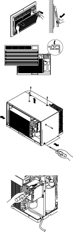
2.1.1 FRONT GRILLE
1. Open the inlet grille downward.
2. Remove the screw which fastens the front grille.
3. Pull the front grille from the right side.
4. Remove the front grille. (See Fig. 1)
5. Re-install the component by referring to the removal procedure.
Figure 1
2.1.2 CABINET
1. After disassembling the FRONT GRILLE, remove the 6 screws which fasten the cabinet at the both sides and the top. (See Fig. 2)
Keep these for later use.
MODE |
|
F |
TIMER |
TEMP |
|
|
|
FAN |
|
|
SPEED |
POWER
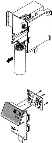
2.1.3 CONTROL BOX
1.Remove the front grille. (Refer to section 2.1.1)
2.Remove the screw which fasten the control box. (See Fig. 3)
3.Pull the control box from the barrier.(See Fig.3)
4.Discharge the capacitor by placing a 20,000 ohm resistor across the capacitor terminals.
5.Disconnect two wire housings in the control box.
6.Pull the control box forward completely.
7.Re-install the components by referring to the
removal procedure. (See Fig. 3)
(Refer to the circuit diagram found on pages 26 in this manual and on the control box.)
Figure 2
Cool
Energy
Saver
Fa 
MODE 
Figure 3
—6—
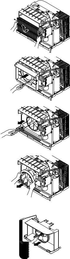
2.2 AIR HANDLING PARTS
2.2.1 ORIFICE, AND TURBO FAN
1.Remove the front grille. (Refer to section 2.1.1)
2.Remove the cabinet. (Refer to section 2.1.2)
3.Remove the 2 screws which fasten the evaporator at the left side and the right side. (See Fig. 4)
4.Move the evaporator sideward carefully.
Figure 4
5. Remove the orifice. (See Fig. 5)
Figure 5
8.Using handheld pliers, remove the clamp which secures the turbo fan. (See Fig. 6)
Figure 6
9.Remove the turbo fan with pliers or your hand, without touching blades. (See Fig. 7)
10.Re-install the components by referring to the removal procedures, above.
Figure 7
2.2.2 FAN
1.Remove the cabinet. (Refer to section 2.1.2)
2.Remove the brace. (Refer to section 2.2.1)
3.Remove the 7 screws which fasten the condenser.
4.Move the condenser sideways carefully.
5.Using handheld pliers, remove the clamp which secures the fan.
6.Remove the fan. (See Fig. 8)
7.Re-install the components by referring to the removal procedures, above.
Figure 8
—7—
2.2.3 SHROUD
1.Remove the fan. (Refer to section 2.2.2)
2.Remove the shroud. (See Fig. 9)
3.Re-install the components by referring to the removal procedures, above.
2.3 ELECTRICAL PARTS
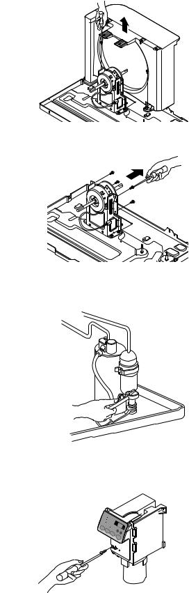
2.3.1 MOTOR
1.Remove the cabinet. (Refer to section 2.1.2)
2.Remove the clamp cord and disconnect the wire housing in control box. (Refer to section 2.1.3)
3.Remove the turbo fan. (Refer to section 2.2.2)
4.Remove the fan. (Refer to section 2.2.2)
5.Remove the 4 or 2 screws which fasten the motor. (See Fig. 10)
6.Remove the motor.
7.Re-install the components by referring to the removal procedures, above.
2.3.2 COMPRESSOR
1.Remove the cabinet. (Refer to section 2.1.2)
2.Discharge the refrigerant system using a FreonTM Recovery System.
If there is no valve to attach the recovery system to, install one (such as a WATCO A-1) before venting the FreonTM . Leave the valve in place after servicing the system.
3.Disconnect the 3 leads from the compressor.
4.After purging the unit completely, unbraze the suction and discharge tubes at the compressor connections.
5.Remove the 3 nuts and the 3 washers which fasten the compressor. (See Fig. 11)
6.Remove the compressor.
7.Re-install the components by referring to the removal procedures, above.
2.3.3 CAPACITOR
1.Remove the control box. (Refer to section 2.1.3)
2.Remove the 1 screw
3.Open the control box
4.Disconnect all the leads on the capacitor terminals.
5.Re-install the components by referring to the removal procedures, above.
Figure 9 |
Figure 10
Figure 11
|
Cool |
|
Ene |
|
|
|
Savrgery |
|
|
Fan |
|
|
|
F1 |
|
|
F3F2 MEDLOW |
|
Ti |
HIGH |
MO |
mer |
'F |
|
TE |
|
DE |
TIMER |
|
|
FAN |
|
|
|
|
|
|
SPEED |
|
|
PO |
|
|
WER |
Figure 12
—8—
2.3.4 POWER CORD
1.Remove the control box. (Refer to section 2.1.3)
2.Unfold the control box. (Refer to section 2.3.3)
3.Disconnect the grounding screw from the Base pan.
4.Disconnect 2 receptacles.
5.Remove a screw which fastens the clip cord.
6.Pull the power cord. (See Fig. 13)
7.Re-install the components by referring to the
removal procedure, above.
(Use only one ground-marked hole,  , for ground connection.)
8.If the supply cord of this appliance is damaged, it must be replaced with the factory-authorized and specified cord.
Figure 13
2.3.5 THERMISTOR
1.Remove the control box. (Refer to section 2.1.3)
2.Unfold the control box. (Refer to section 2.3.3)
3.Disconnect all the leads of thermistor terminals.
4.Remove the thermistor. (See Fig. 14)
5.Re-install the components by referring to the removal procedures, above.
C |
|
|
ool |
|
|
Energy |
|
|
Saver |
|
|
Fan |
F1 |
|
|
LOW |
|
|
F2 |
|
|
F3 |
MED |
Timer |
|
HIGH |
|
'F |
|
MODE |
|
|
TIMER |
FAN |
|
|
|
|
|
SPEED |
POWER |
|
|
Figure 14
—9—
2.4 REFRIGERATION CYCLE
CAUTION
Discharge the refrigerant system using a FreonTM Recovery System.
If there is no valve to attach the recovery system, install one (such as a WATCO A-1) before venting the FreonTM. Leave the valve in place after servicing the system.
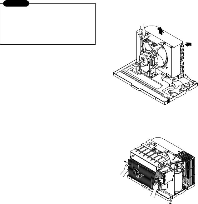
2.4.1 CONDENSER
1. Remove the cabinet. (Refer to section 2.1.2)
2. Remove the brace. (Refer to section 2.2.1)
3. Remove the 7 screws which fasten the condenser.
4. After discharging the refrigerant completely into a FreonTM Recovery System, unbraze the interconnecting tube at the condenser connections.
5.Remove the condenser.
6.Re-install the components by referring to the notes
(See Fig. 15) |
Figure 15 |
2.4.2 EVAPORATOR
1.Remove the cabinet. (Refer to section 2.1.2)
2.Discharge the refrigerant completely – into a
FreonTM Recovery System.
3. Remove the 2 screws which fasten the evaporator at the left side and the right side.
4. Move the evaporator sideward carefully and then unbraze the interconnecting tube at the evaporator connectors.
5. Remove the evaporator.
6. Re-install the components by referring to the notes (See Fig. 16)
Figure 16
2.4.3 CAPILLARY TUBE
1.Remove the cabinet. (Refer to section 2.1.2)
2.After discharging the refrigerant completely – into a FreonTM Recovery System, unbraze the interconnecting tube at the capillary tube.
3.Remove the capillary tube.
4.Re-install the components by referring to the notes.
Cool |
Fan |
MODE |
Timer |
'F |
TIMER |
TEMP |
|
|
SPFAN |
|
|
|
|
|
|
EED |
POWER
—10—
NOTES
—Replacement of the refrigeration cycle.
1.When replacing the refrigeration cycle, be sure to discharge the refrigerant system using a FreonTM recovery System.
If there is no valve to attach the recovery system, install one (such as a WATCO A-1) before venting the FreonTM. Leave the valve in place after servicing the system.
2.After discharging the unit completely, remove the desired component, and unbrace the pinch-off tubes.
3.Solder service valves into the pinch-off tube ports, leaving the valves open.
4.Solder the pinch-off tubes with Service valves.
5.Evacuate as follows.
1)Connect the vacuum pump, as illustrated Fig. 17A.
2)Start the vacuum pump, slowly open manifold valves A and B with two full turns counterclockwise and leave the valves closed. The vacuum pump is now pulling through valves A and B up to valve C by means of the manifold and entire system.
CAUTION
If high vacuum equipment is used, just crack valves A and B for a few minutes, then open slowly with the two full turns counterclockwise. This will keep oil from foaming and being drawn into the vacuum pump.
3)Operate the vacuum pump for 20 to 30 minutes, until 600 microns of vacuum is obtained. Close valves A and B, and observe vacuum gauge for a few minutes. A rise in pressure would indicate a possible leak or moisture remaining in the system. With valves A and B closed, stop the vacuum pump.
4)Remove the hose from the vacuum pump and place it on the charging cylinder. See Fig. 17B. Open valve C.
Discharge the line at the manifold connection.
5)The system is now ready for final charging.
6.Recharge as follows :
1)Refrigeration cycle systems are charged from the High-side. If the total charge cannot be put in the High-side, the balance will be put in the suction line through the access valve which you installed as the system was opened.
2)Connect the charging cylinder as shown in Fig. 17B. With valve C open, discharge the hose at the manifold connection.
3)Open valve A and allow the proper charge to enter the system. Valve B is still closed.
4)If more charge is required, the high-side will not take it. Close valve A.
5)With the unit running, open valve B and add the balance of the charge.
a.Do not add the liquid refrigerant to the Lowside.
b.Watch the Low-side gauge; allow pressure to rise to 30 lbs.
c.Turn off valve B and allow pressure to drop.
d.Repeat steps B and C until the balance of the charge is in the system.
6)When satisfied the unit is operating correctly, use the pinch-off tool with the unit still running and clamp on to the pinch-off tube. Using a tube cutter, cut the pinch-off tube about 2 inches from the pinch-off tool. Use sil-fos solder and solder pinch-off tube closed. Turn off the unit, allow it to set for a while, and then test the leakage of the pinch-off connection.
—11—

Equipment needed: Vacuum pump, Charging cylinder, Manifold gauge, Brazing equipment. Pinch-off tool capable of making a vapor-proof seal, Leak detector, Tubing cutter, Hand Tools to remove components, Service valve.
CONDENSER |
COMPOUND GAUGE |
|
|
|
|
|
|
(HIGH PRESSURE SIDE) |
MANIFOLD |
|
|
|
|
||
|
|
GAUGE |
A |
|
|
B |
|
CAPILLARY TUBE |
|
|
|
|
|
SEE INSETS |
|
|
|
BELOW |
|
|
|
EVAPORATOR |
|
|
|
(LOW PRESSURE SIDE) |
|
COMPRESSOR |
|
|
|
|
LOW |
HI |
|
A |
|
|
|
B |
B |
A |
|
EXTERNAL |
|
|
|
VACUUM PUMP |
|
|
|
|
|
CHARGING |
|
|
|
CYLINDER |
|
|
|
C |
|
Figure 17A-Pulling Vacuum |
Figure 17B-Charging |
|
|
—12— |
|
|
|
 Loading...